

Vintage Cellars SLK Series Evaporator User Manual
SLK Series Evaporator
• Extremely Quiet Operation
• Low Profile, Wall Mounted
• R-22 Refrigerant
• 2600-4010 BTU capacity
• Available Options
1. Outdoor Condenser
2. Electronic Thermostat with
Digital Display
3-10

INSTALLATION INSTRUCTIONS
CAUTION
This equipment should be installed only by a qualified technician.
1. Select a location for the evaporator coil. The Ideal location would be directly across from the entrance door.
This will purge the entrance area when the door is opened, However since wine cellars are closed most of the
time this is not critical. . Mount the evaporator coil to the ceiling leaving a distance equal to the height of the
unit, minimum, to the wall to allow for proper airflow. If you have a air handler system refer to the additional
information supplied. Wall mount units require no additional space, except to ensure that air flow is not
restricted. Refer to information supplied with the evaporator for more specific information.
2. Place the condenser at the desired location (must be outside the wine cellar in a well ventilated area or
outside). When installing an outdoor condenser be sure that it is located so snow or leaves will not pile up and
block air flow. This can be accomplished by setting the condenser on concrete blocks Etc.
3. Install a line set sized according to Table 1. Insulate the vapor line the entire length of the run. Be sure to
install a “P” trap in the suction line, several may be required if the condenser is higher than the evaporator.
4. Connect your gauges and Vacuum Pump to the condenser and Evacuate the system.
5. While the system is being evacuated, install the thermostat following the manufactures instructions and run
the thermostat wire to the condenser unit, use the R and Y Terminal on the thermostat subbase, connect to the
yellow and red wires in the condenser unit, if the system is an indoor unit use the R and G terminal on the
control relay. On air handler systems refer to the drawing for that system.
If possible, place the thermostat or sensor on the same wall as the evaporator coil near the evaporator air inlet.
This will cause the thermostat to sense the air returning to the evaporator and should cool the entire room
before the unit shuts off, Preventing compressor short cycling
6. Charge the unit with R22 according to Table 1 (or until bubbles appear in the sight glass. Continue to slowly
add Refrigerant until the bubbles just disappear).
7. After the unit has run about 10 minutes check the sight glass. Under normal operation there should be no
bubbles, If there is, the system is low on Refrigerant, Add Refrigerant to eliminate bubbles.
8. When the wine room has reached 55 Degrees Check the sight glass again and the gauge readings. Suction
pressure should be in the range of 65 to 78. Liquid pressure should be in the range of 250 to 300. Check the
superheat (8-15°) and if necessary adjust the expansion valve to compensate.
Unit Size Liquid Line Vapor Line Refrigerant Req
2600 BTU 1/4 3/8 2.4 Lbs
4100 BTU 1/4 3/8 2.6 Lbs
5710 BTU 1/4 1/2 2.6 Lbs
7600 BTU 1/4 1/2 2.8 Lbs
10200 BTU 3/8 1/2 4.2 Lbs
10900 BTU 3/8 1/2 4.2 Lbs
13400 BTU 3/8 5/8 4.8 Lbs
18100 BTU 3/8 7/8 6.2 Lbs
22000 BTU 3/8 7/8 8.0 Lbs
Table 1
5-1
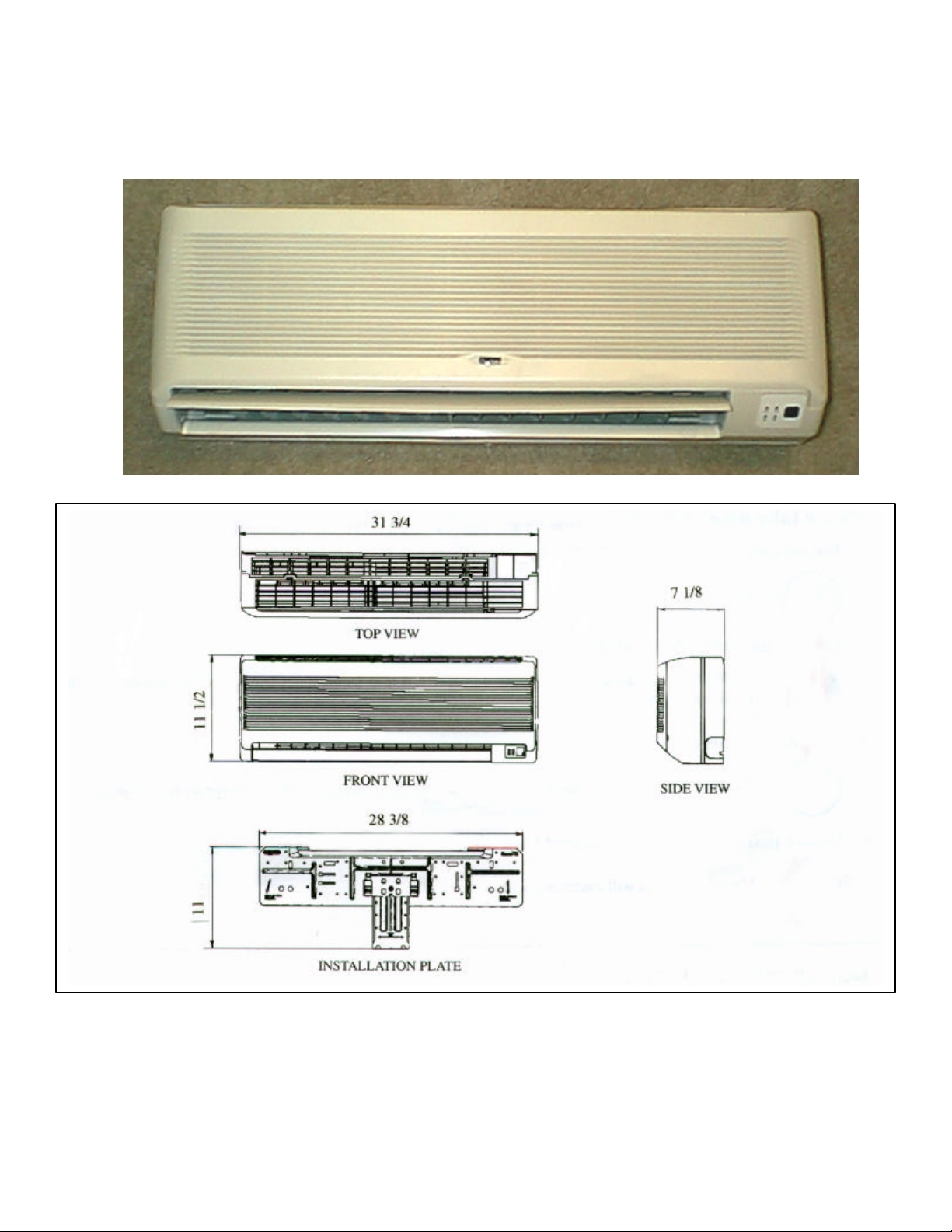
INDOOR UNIT
b
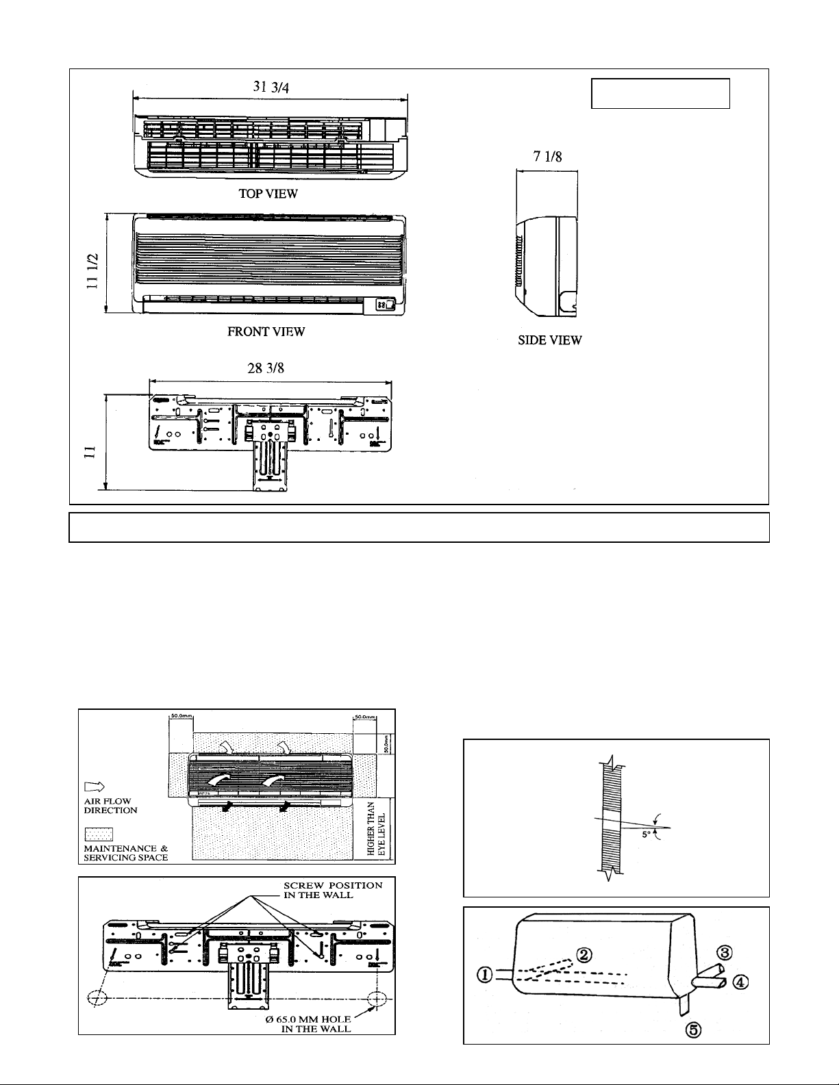
INSTALLATION OF THE INDOOR UNIT
The indoor unit must be installed so that there is
no short circuit of the cool discharge air with the
hot return air. Please follow the installation
clearance shown in the figure. Do not place the
indoor unit where there could be direct sunlight
shinning on the unit. Also, this location must be
suitable f or piping and drainage and be away
from the door or window.
Figure C
Figure D
MOUNTING INSTALLATION PLATE
Ensure that the wall is strong enough to
support the weight of the unit. Use the
plumb line for horizontal mounting, and
fix it with 4 suitable screws.
If the lines are through the wall, drill a
65mm hole at the proper location. It should
e slightly lower on the outside of the wall
Figure E
INDOOR SIDE
OUTDOOR SIDE
 Loading...