

Page 1
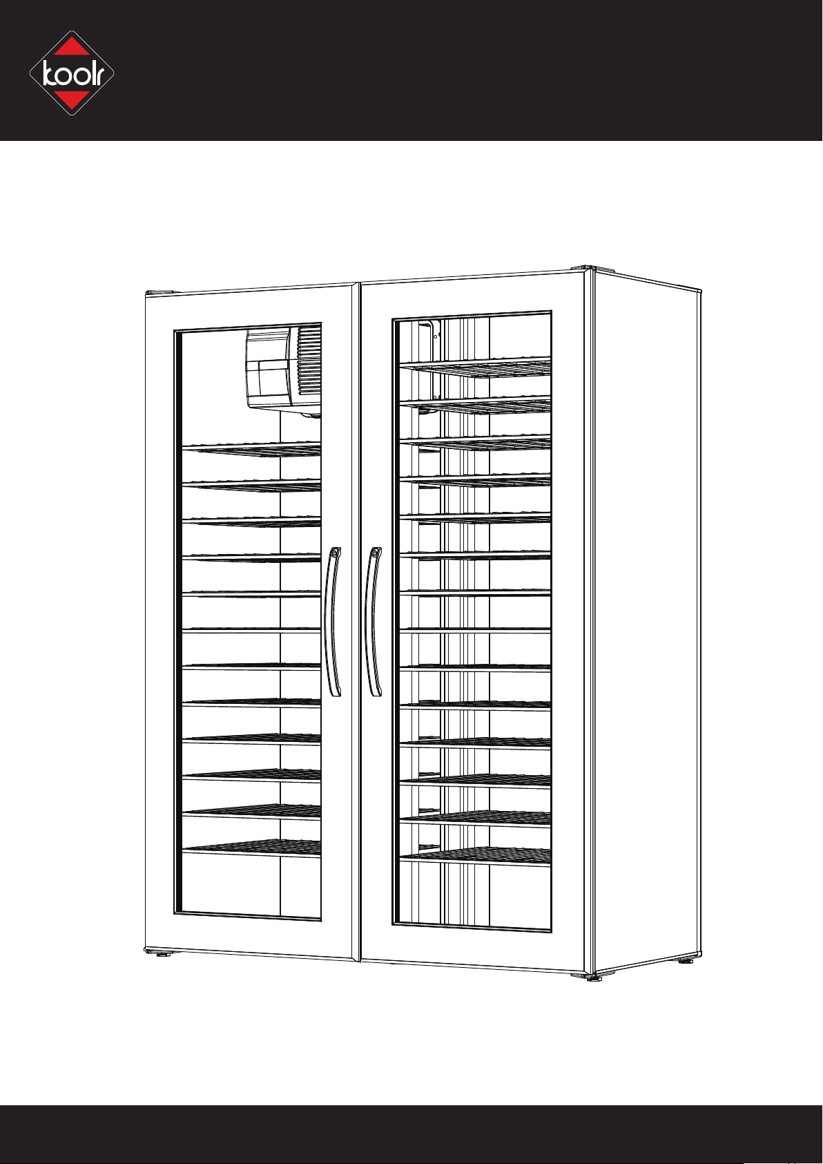
TM
WineKoolR
250 500
ASSEMBLY & OPERATION MANUAL
Page 2
READ THE "USE AND CARE GUIDE" BEFORE YOU START
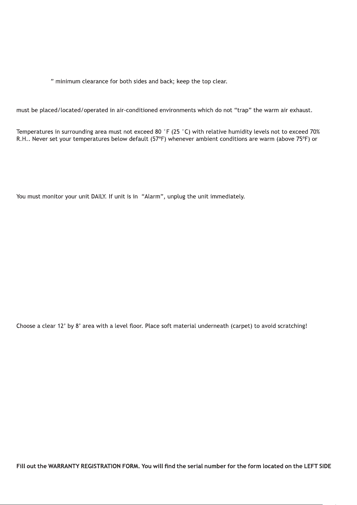
LOCATING YOUR WINE CELLAR
Provide 2
Never locate your wine cellar outdoors or in an area with extremes of temperature and humidity. These units
humid (above 50%R.H.).
Outlet power must be a DEDICATED separately fused, grounded, 15 Amp 110 - 120 V line or 7.5 Amp - for 240 V
models (CHECK BOX OR SERIAL NUMBER LABEL ON UNIT FOR YOUR LINE VOLTAGE REQUIREMENTS).
KoolR Products will not be liable or responsible for incidental or consequential damages. (See Warranty).
Place unit in a clean area and allow access to the exterior surfaces for periodic vacuuming of the condenser coil.
(See troubleshooting for details.)
1/2
TM
Clean using a damp cloth and no detergents or polishes under any circumstances.
Always remove all bottles before relocating your wine cellar.
AREA FOR ASSEMBLING YOUR WINE CELLAR
TOOLS
Rubber mallet, hex wrench (included), phillips screwdriver.
Helper is needed.
TEST THE COOLING UNIT
Plug it in on a table top, to verify that controls and display are functional, and that the unit is producing cool air
after a few minutes of operation.
Note that the electronic controller has a one-minute safety delay between initial plug-in and start-up of the
compressor.
BEFORE YOU START !
of the unit or on the light cord.
~ 2 ~
Page 3
TOP
LEFT
REAR
TOP
RIGHT
REAR
SPACER
HARDWARE
HINGES VENT
x 2
x 2
CONNECTOR PLATES
x 2
x 1
x 1
A
B
x 1
C
x 1
x 1
D
Hinge Washer
x 2
E
Hooks
x 2
F
Power supply
x 1
Legs
x 6
Cooling Unit Bolts
in cooling unit box
G
Wrench
x 1
x 2
H
G
Anchors x 2
in cooling unit box
I
Model 250 only !
Screws x 2
Allen
x 1
J
Wall Ties x 2
Brace
x 4
Handle and Lock
x 2
~ 3 ~
Spacer
x 2
Shelves
x 26
Page 4
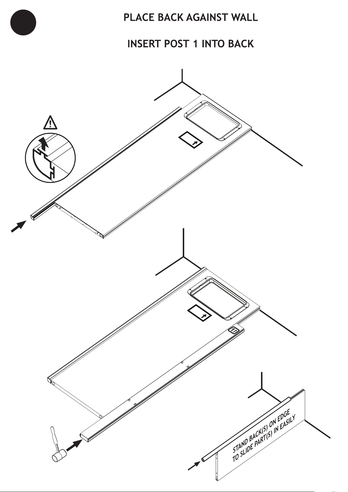
1
INSERT CORNER (LEFT ONLY)
WALL
BACK
PLACE AGAINST WALL
BACK
BACK
PLACE AGAINST WALL
FLOOR
WALL
BACK
POST 1
~ 4 ~
FLOOR
TIP
WALL
FLOOR
Page 5
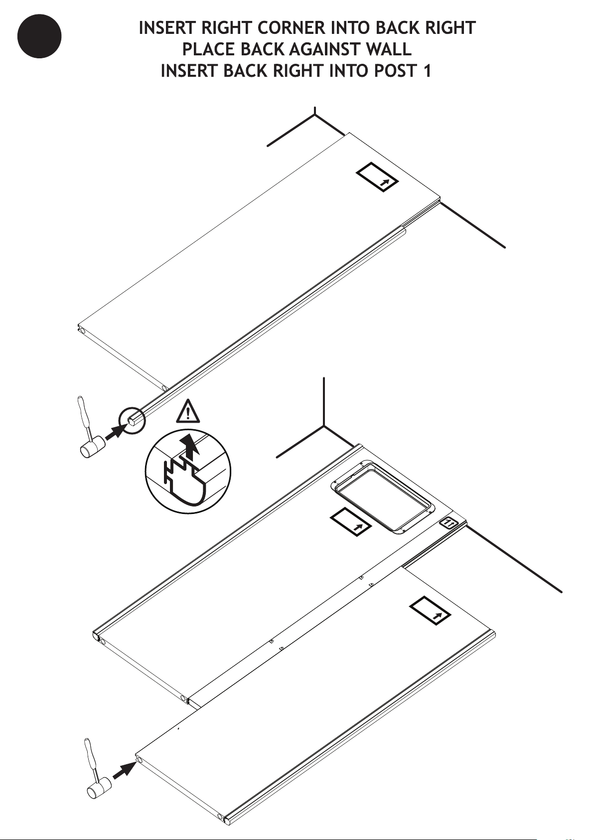
2
BACK
PLACE AGAINST WALL
BACK
RIGHT
BACK
RIGHT
BACK
RIGHT
WALL
FLOOR
INSERT
BACK
POST 1
BACK
RIGHT
WALL
FLOOR
~ 5 ~
RIGHT CORNER
Page 6
BACK
PLACE AGAINST WALL
LEFT
BACK
RIGHT
LEFT
RIGHT
WALL
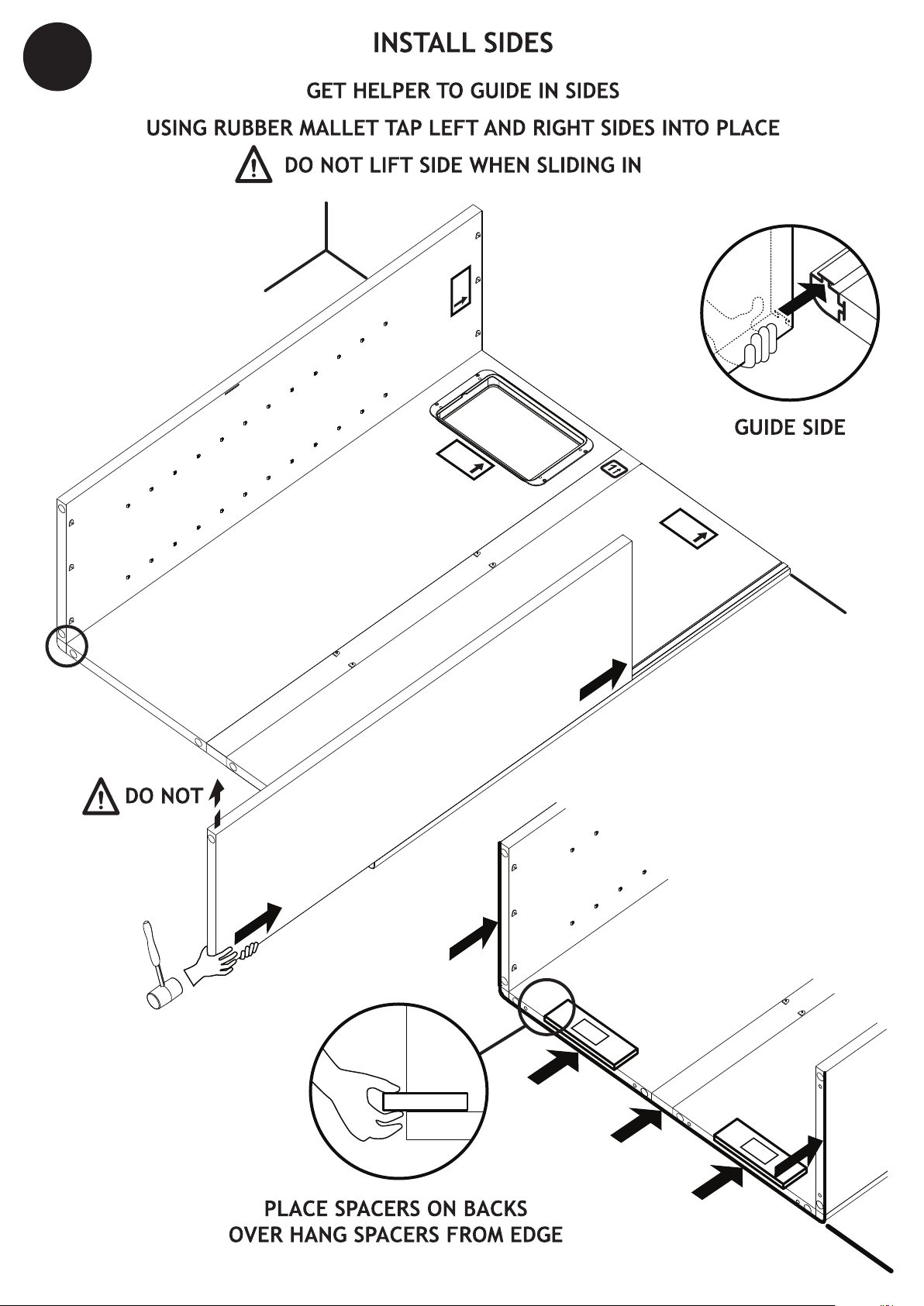
SPACER
SPACER
BACK
PLACE AGAINST WALL
LEFT
LEVEL
LEFT
3
TO TAB
LIFT
PUSH OR TAP
AT BOTTOM
SPACER
~ 6 ~
Page 7
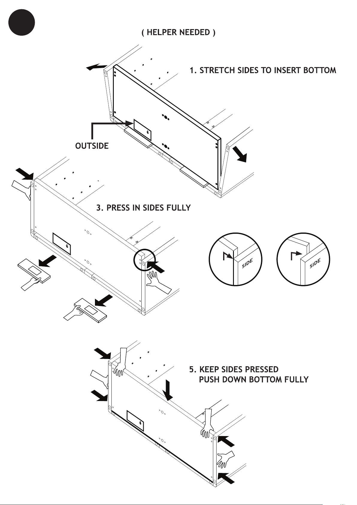
BACK
RIGHT
BACK
PLACE AGAINST WALL
BOTTOM
OUTSIDE
BACK
4
OK
NO
SPACER
SPACER
BOTTOM
OUTSIDE
BACK
BACK
PLACE AGAINST WALL
LEFT
BOTTOM
BOTTOM
BACK
PLACE AGAINST WALL
LEFT
BOTTOM
OUTSIDE
BACK
BOTTOM
PRESS
PRESS
PRESS
PRESS
INSTALL BOTTOM
2. REST BOTTOM ON SPACERS
4. PULL OUT
SPACERS
~ 7 ~
Page 8
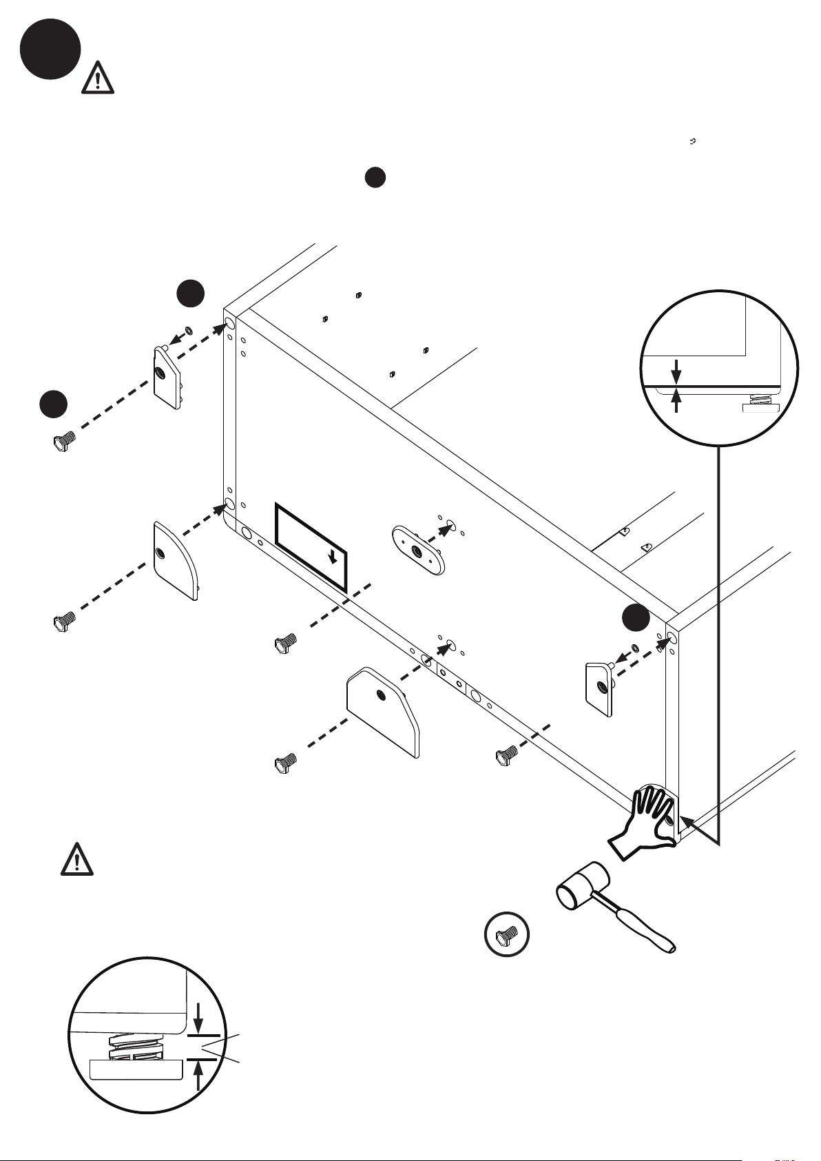
INSTALL BOTTOM CONNECTOR PLATES
5
WARNING! Connector plates can be removed ONLY as described on page 19.
HAND PRESS IN ALL CONNECTOR PLATES IN BOTTOM
TAP IN CONNECTORS TIGHTLY (NO GAP) WITH CLOSED HAND OR RUBBER MALLET
B
LEGS
WASHER
HINGE 2
BOTTOM
LEFT
REAR
SCREW IN ALL LEGS
B
A
BOTTOM
BOTTOM
OUTSIDE
BACK
BOTTOM
CENTER
FRONT
NO GAP!
WASHER
A
LEAVE 1/4” SPACING ON CORNER LEGS
LEAVE 1/2” SPACING ON CENTER LEGS
1/4” SPACING ON 4 CORNERS (Easy access in upright position for final leveling.)
1/2” SPACING ON CENTERS (Limited access in upright position.)
HINGE 1
CENTER
REAR
BOTTOM
RIGHT
REAR
TAP
GENTLY
~ 8 ~
Page 9

6
INSTALL TOP
A: INSERT TOP VENT
CHECK ORIENTATION
VENT
OUTSIDE
TOP
PRESS FOR
FIRM LOCK
(OPPOSITE SIDE)
~ 9 ~
Page 10

BACK
PLACE AGAINST WALL
LEFT
TOP
OUTSIDE
BACK
6
BACK
PLACE AGAINST WALL
LEFT
TOP
OUTSIDE
BACK
TOP
RIGHT
REAR
TAP
GENTLY
TOP
LEFT
REAR
CENTER
REAR
TOP
PRESS
PRESS
PRESS
PRESS
INSTALL TOP
B:
REPEAT STEP ON PAGE 7 FOR TOP
4
TOP
DO NOT INSTALL HINGES YET!
WARNING! HINGES can be removed ONLY as described on page 19.
INSTALL TOP CONNECTOR PLATES
NO HINGE
NO HINGE
~ 10 ~
Page 11

7
2
4
3
TOP
SLOTS
INSTALL CENTER POSTS
~ 11 ~
Page 12

8
HINGE 2
TOP
HINGE 1
TAP
GENTLY
PLACE WASHERS FIRST
INSTALL TOP HINGES
WASHER
ON BOTTOM
HINGES ONLY
A
NOTE: DOOR GASKET WILL RELAX IN A FEW DAYS ASSURING A GOOD SEAL
Door is made of very tough PLEXIGLAS, but it can be scratched.
~ 12 ~
Handle and clean with care!
Page 13

9
!
!
"
"
CELLAR BOTTOM
"
TABS
INSTALL BRACES 5 AND 6 (7)
(HELPER NEEDED TO HOLD CABINET STEADY)
ALIGN TO TABS, PUSH DOWN BRACES 5 (× 2)
AND 6 or 7 (× 2)
~ 13 ~
Page 14

PRESS
10
PRESS
INSTALL SHELVES
TAB REFERENCE
SHORTER
FRONT
LONGER
START AT MIDDLE
PRESS IN SIDES
CLICK SHELF
OVER TABS
SHELF
TAB
CELLAR BOTTOM
~ 14 ~
Page 15

11
LEVEL TO
OPENING
PLACE COOLING UNIT IN CABINET
CLEAR OPENING
STRAIGHTEN AND
PUSH THROUGH
GET HELPER TO
PULL FROM INSIDE
AND LIFT UNIT
LEVEL DURING
FASTENING
C
COOLING UNIT
CHECK AFTER TIGHTENING !!!
VENT
MUST SEAL !
IN COOLING
UNIT BOX.
TIGHT!
UP
~ 15 ~
Page 16

ON BOTTOM
HINGES ONLY
W ASHER
A
12
Wine
List
3
13
1
2
Connect the power to
1.
the power supply(F)
Stick the power supply
2.
to the top panel
Connect the low voltage
3.
plug to the voltage
Door latch:
DOWN (Hinge on Left)
UP (Hinge on Right)
~ 16 ~
Page 17

14
LEVEL CELLAR
LEVEL DOORS
ADJUST OUTER LEGS TO LEVEL DOORS
HINGES ARE PRE-SET
ADJUSTMENTS SHOULD NOT BE REQUIRED
~ 17 ~
G
UP
D
Page 18

WALL
15
BRACE TO WALL - for 250 models ONLY
RISK OF INJURY !
IF CABINET IS NOT FULLY LOADED IN THE BOTTOM IT CAN BE TOP HEAVY.
TO AVOID INJURY OR DAMAGE ALWAYS BRACE TO WALL !
WALL MATERIALS VARY, USE APPROPRIATE ANCHORS FOR YOUR APPLICATION.
G
G
DO NOT
PRESS IN FULLY
DRILL USING 1/4” (6 - 6.5 mm) DRILL BIT AND TAP IN ANCHORS
PRESS IN FULLY WALL TIES INTO REAR CONNECTOR PLATES AND SCREW IN SCREWS
I
H
H
!
I
NEVER MOVE LOADED CABINET!
EMPTY FIRST!
~ 18 ~
Page 19

REMOVE COOLING UNIT AND SHELVES
!"##"$
"%#&'()
!*+,
LAY CELLAR DOWN
FULLY TIGHTEN LEGS
PRY OFF ALL CONNECTOR PLATES WITH FLAT SCREWDRIVER
REUSE LEG
FOR TOP HINGE
AND CENTER REAR
TIGHTEN LEGS
FULLY
~ 19 ~
PRY OFF
CONNECTOR PLATE
Page 20

(wait one minute)
Calibration option of the temperature sensor.
Display of actual temperature by request.
Digital temperature sensor.
Settings are stored in memory for power failures.
+
-
delay of 1 minute the fan will start, followed by the
compressor within the next minute.
The unit will cycle ON/OFF based on the temperature reading. Fan speeds are automatically set by the controller to achieve optimum
performance.
Minimum ON and OFF cycle times are imposed by software, to prevent "short cycling".
OPERATION
Actual temperature: PRESS
SET temperature: PRESS
PRESS and RELEASE
TEMPERATURE
(range is 53-64
TO CHANGE FROM
A negative offset will result in a warmer cabinet and a positive offset will result in a cooler cabinet.
The new value will be memorized and the controller will reset automatically.
To increase: PRESS once per degree
To decrease: PRESS once per degree
The new value will be memorized and the controller will reset automatically.
The new value will be memorized and the controller will reset automatically.
Wait 5 seconds
USE for each degree of positive offset
for each degree of negative offset
CONTROLLER
ACTION
BEFORE AFTER
57 56
70 57
57 57
57 58
57 56
57 14
57 57
57 F0
F0 F1
F0 -1
KEYS
alternating with the temperature reading.
- Unplug and re plug the unit after 10 minutes.
~ 20 ~
Page 21

MAXIMUM CAPACITIES AND LOADING TIPS
Maximum capacities and sample loading arrangements for WineKoolR wine cellars are illustrated below. Standard
Burgundy and Bordeaux bottles are best arranged with necks facing out; some taller bottles may need to be arranged
neck to neck. Never stack bottles more than two rows high on a shelf; all shelves must be installed as directed. Avoid
placing bottles directly in front of the cooling unit’s circulating fan for more uniform temperature in cabinet.
TM
Specialized
Bottles
1/2 bottle
Ice wine
Magnum
Standard
Bordeaux 3”
Burgundy 3.25”
750 ml bottles
Champagne 3.5”
Standard bottles
Odd sized bottles
or Case storage
25
MODEL 250
6
7
7
7
7
7
7
7
7
7
7
7
Standard
750 ml bottles
13
21
MODEL 500
Specialized
Bottles
1/2 bottle
7
7
7
7
7
7
7
7
7
7
7
7
7
Ice wine
Magnum
Standard
Bordeaux 3”
Burgundy 3.25”
750 ml bottles
Champagne 3.5”
Standard bottles
Odd sized bottles
or Case storage
50
6
14
14
14
14
14
14
14
14
14
14
14
Standard
750 ml bottles
26
14
14
14
14
14
14
14
14
14
14
14
14
14
42
Maximum capacity 250 bottles
Based on 10% (25 x 1/2 bottles)
Maximum capacity 500 bottles
Based on 10% (50 x 1/2 bottles)
Chiller section
Long term Aging section
Short term Holding section
IMPORTANT NOTE
The top shelf of the cabinet should have the coldest temperature and may be used as your “chilling” section.
All Wine Cabinets have minor differences in temperature depending on where articles are stored. Top to Bottom
differences will be present in any Cellar due to layering and pressure differences. The coldest temperatures will
occur closest to the “Top” where the cold air originates.
The temperature readout represents samples of the air close to the position of the sensor. Other points in the cabinet
will vary according to many factors, including the type of bottle loading, proximity to the door, corners, exposure to
outside temperature, door usage etc. Just as in air conditioned rooms and refrigerators, not all locations measure the
same temperature.
For example if you measure the air temperature exiting the coil, it will always be substantially colder than the set
air back into the cooling unit causing short cycles.
Remember, the important element for storing wine is constant temperature, not absolute temperature. We do guaran-
1/4 of a degree C.
~ 21 ~
Page 22

Although each WineKoolR cooling unit has been carefully tested at every stage of manufacture, occasional problems
TM
arise, the majority of which are due to rough or careless handling during shipping or installation. Other issues may occur
due to improper cabinet assembly, power interruption or surge, low line voltage (less than your unit rating of 105V or
240V), or failure to clean the unit regularly (see illustration below). The following may help you determine what the problem may be; what steps you can take to correct it, and what further steps may be required. Additional Trouble-Shooting
information and downloadable documents are available in the “Support” area of our website: www.koolr.com
Coil is located at the top of back
panel, vacuum it periodically.
In order to provide maximum protection for your valuable wine collection, the following steps are highly advisable.
First and foremost, have your wine collection adequately insured. Second, install a battery-powered heat-sensitive alarm
unit as directed, on a regular basis. Every 3 to 4 months vacuum the cooling unit coils (check our website for more info).
Be advised, also, that
KoolR Products
™
cannot in any event be liable or responsible
for incidental or
consequential damages.
IF: CHECK: THEN:
COOLING UNIT DOES
NOT RUN AT ALL WHEN
PLUGGED IN
COOLING UNIT RUNS BUT
DOES NOT COOL
SUFFICIENTLY
Is the unit plugged in?
Is the power supply operational?
Is the LED display functional?
gnippihs fo ecnedive yna ereht sI
damage on the cooling unit or
packaging materials?
Is the storage temp properly set?
Is the cabinet properly assembled?
unit unobstructed?
Is the ambient air temperature
Are any exterior surfaces of the
cabinet exposed to sunlight?
Note that the unit has a 1-minute cautionary delay
between plugging in and full start-up; this is a
built-in safeguard to protect the compressor in the
event of sudden power failure
Note that the power supply must be a dedicated,
separately-fused and grounded 15 Amp, 120V line
or 7.5 Amp, 240 V line rated for your unit. Must not
use an extension cord. Do not share the outlet with
other appliances
If the unit is receiving power yet fans or compressor
fail to run, unplug for ten minutes, then try again.
for more help please go to :
www.koolr.com/support.html
(Troubleshooting)
Note that the unit may take a few days to achieve
the desired storage temperature, even in a properly
located, airtight cabinet
Take steps to reduce ambient temperatures and
compensate for additional heat gain if any cabinet
walls receive direct sunlight
Take steps to improve circulation of air to and from
the unit
Adjust the legs to level the door for proper magnetic gasket seal
Increase your SET TEMPERATURE
Clean the grill areas
If the problem persists, go to our website at
www.koolr.com/support.html
~ 22 ~
Page 23

For detailed information consult the Warranty
section of the "USE and CARE" guide!
If your WineKoolR™ cooling unit or cabinet fails to perform as designed within one year of the date of purchase, KoolR Products™
warrants that, upon your request, it will be repaired or replaced, at our option, during the one year warranty period.
tinental United States or Canada (excludes Alaska and Hawaii). It is not valid for subsequent purchasers, nor for units in use outside
North America. The warranty period for your cooling unit commences on the date you purchased it and expires one year thereafter.
PROOF OF PURCHASE
Within 10 days of purchase, complete and mail, fax or e-mail the registration sheet to
your warranty on our Internet website,
dated bill of sale to establish your date of purchase.
www.koolr.com. When you make a warranty claim, you must forward a copy of your original
WineKoolR™
cooling unit that is purchased and used in the con-
. Alternately, you may register
KoolR Produ
cts™
IF YOU HAVE A P
Customer service and warranty problems are handled online at
and easy-to-use solution to almost any question or problem you may have. The inquiry forms are filled in on-line and connect you to our
representatives who will process your requests for warranty service. This is the quickest way to solve your problems.
REPLACEMENT ?
At our option we may choose to offer you a replacement part or produ
replacement unit and with appropriate security (credit card authorization), we will promptly ship a replacement unit. The replacement may be a unit that has been reconditioned by
returned to us, shipping prepaid. Upon its receipt, we will release your credit card security. Go online to the SUPPORT section on our
website at
Your unit is designed to perform with a minimum amount of user maintenance when installed and operated precisely as directed in
the manual.
of the condensor coil. Also, you must take steps to protect the unit from sudden power surges. As with any sensitive electronic device,
your
WineKoolR™
interruptions or prolonged low-voltage conditions, which are not covered by this Warranty. You must monitor your unit’s
performance on a daily basis. If there is an apparent problem or “Alarm” condition, you must disconnect the power supply to avoid
potential damage to your wine collection.It is your responsibility to insure y
precautions to safeguard its condition.
ROBLEM WITH YOUR UNIT
KoolR Products™
www.koolr.com to request warranty service.
cooling unit may be damaged by power surges or spikes, including lightning strikes, acts of God, sudden
www.koolr.com. You will find a comprehensive well documented
ct rather than a repair. Upon your authorization to accept a
. The unit that needs service must be packed and
our wine, and to take all reasonable and necessary
WHAT THE WARRANTY DOES NOT COVER
This warranty covers only defects in materials and workmanship provided by
or malfunction from misuse, abuse, accident, acts of God, or any unauthorized alteration or modification. The product must have
been installed and operated precisely as directed in the manual which accompanies each product. Improper retu
packaging or shipping damage is not covered unless the unit is packaged and shipped in accordance with
replacement procedures. Third party servicing of this product during the warranty period will also void the warranty, as will any
evidence of tampering or alteration to the serial number and or the original dated bill of sale.
KoolR Products™
and does not cover equipment damage
rn shipping, inadequate
KoolR Products™
YOUR ONLY REMEDY UNDER THIS WARRANTY IS THE REPLACEMENT OR REPAIR OF YOUR EL
THER THIS WARRANTY NOR ANY OTHER WARRANTY, EXPRESS OR IMPLIED, INCLUDING, BUT NOT LIMITED TO, THE IMPLIED WARRANTIES
OF MERCHANTABILITY AND FITNESS FOR A PARTICULAR PURPOSE, SHALL EXTEND BEYOND THE ONE-YEAR WARRANTY PERIOD. UNDER NO
CIRCUMSTANCES SHALL
CONSE
QUENTIAL DAMAGES, INCLUDING SPOILAGE OFWINE, EVEN
POSSIBLE.
CONDITION. SOME STATES DO NOT ALLOW THE EXCLUSION OR LIMITATION OF INCIDENTAL OR
EXCLUSION OR
ADDITIONAL WARRANTY
cian, or y
serial number, and your credit card. Let us assure you that local servicing will always be a more expensive and less satisfactory solution. More often than not repairs are not properly done and almost always take longer and cost more than purchasing a discounted
new unit. Go online at
IT IS YOUR RESPONSIBILITY TO INSURE YOUR WINE, AND TAKE ALL REASONABLE, NECESSARY PRECAUTIONS TO SAFEGUARD ITS
LIMITATION
ou may purchase a new unit at a special discount under our Extended Warranty Program. Please be ready to provide model,
KoolR Products™
MAY NOT APPLY TO YOU. NO
OFFERED BY A RESELLER IS THE SOLE RESPONSIBILITY OF THAT RESELLER.
www.koolr.com to request Replacement or see our Extended Warranty Program.
BE LIABLE FOR ANY SPECIAL INCIDENTAL, INDIRECT OR PUNITIVE DAMAGES OR FOR ANY
IF
KoolR Products™
RESELLER ISAUTHORIZED
TO MODIFY THE TERMS OF THIS
IGIBLE PRODUCT AS DESCRIBED ABOVE. NEI-
KNOWS OR IS
INFORMED
CONSEQUENTIAL
THAT SUCH
DAMAGES, SO THE ABOVE
WARRANTY.
DAMAGES
ARE
ANY
-
~ 23 ~
Page 24

TM
WineKoolR
250 500
ASSEMBLY & OPERATION MANUAL
 Loading...