

Vintage Cellars Slimline 120 User Manual
TM
WineKoolR
120
ASSEMBLY & OPERATION MANUAL

Read the "USE and CARE" guide before you start !
LOCATING YOUR WINE CELLAR
Provide 2
Never locate your wine cellar outdoors or in an area with extremes of temperature and humidity. These units must be
50%R.H.).
Outlet power must be a DEDICATED separately fused, grounded, 15 Amp 110 - 120 V line or 7.5 Amp - for 240 V models
(CHECK BOX OR SERIAL NUMBER LABEL ON UNIT FOR YOUR LINE VOLTAGE REQUIREMENTS).
KoolR Products will not be liable or responsible for incidental or consequential damages. (See Warranty).
Place unit in a clean area and allow access to the exterior surfaces for periodic vacuuming of the condensor coil.
(See troubleshooting for details).
1/2
TM
Clean using a damp cloth and no detergents or polishes under any circumstances.
Always remove all bottles before relocating your wine cellar.
AREA FOR ASSEMBLING YOUR WINE CELLAR
TOOLS
Rubber mallet, Allen key (included), Adjustable wrench, Phillips screwdriver, D r i l l .
Helper is needed.
TEST THE COOLING UNIT
Plug it in on a table top, to verify that controls and display are functional, and that the unit is producing cool air after a few
minutes of operation.
Note that the electronic controller has a one-minute safety delay between initial plug-in and start-up of the compressor.
BEFORE YOU START !
the unit or on the light cord.
~ 2 ~
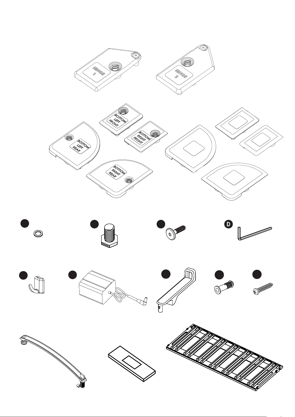
HINGES
HARDWARE
CONNECTOR PLATES
A
x 1
x 1
x 1
x 1
x 1
B
C
x 1
RIGHT
REAR
x 1
TOP
x 1
x 1
REAR
RIGHT
FRONT
TOP
LEFT
TOP
LEFT
FRONT
x 1
TOP
Bottom Hinge
Washer
x 1
E
Hooks
x 2
Handle and Lock
x 1
F
Power supply
x 1
Legs
x 4
SPACER
Spacer
x 1
Cooling Unit Bolts
in cooling unit box
x 2
G
Wall Ties
x 2
Shelves
x 12
H
G
Anchors
x 2
Allen Key
in cooling unit box
x 1
I
Screws
x 2
~ 3 ~
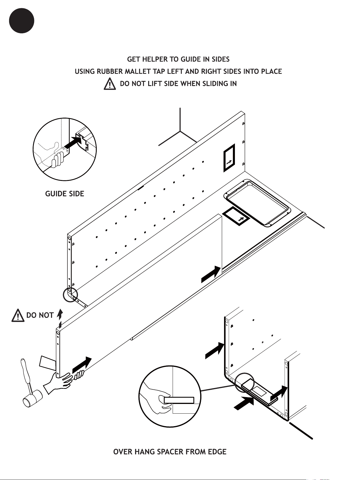
SPACER
1
INSERT SIDES
LAY BACK ON FLOOR AGAINST WALL
LEFT
WALL
LIFT
TO TAB
LEFT
RIGHT
BACK
PLACEAGAINST WALL
LABEL SIDE UP!
BACK
FLOOR
PUSH OR TAP
AT B OT TOM
BACK
SPACER
LEVEL
PLACE SPACER ON BACK
~ 4 ~
BOTTOM
OUTSIDE
BACK
SPACER
BO
TTOM
OUTSIDE
BACK
BOTTOM
OUTSIDE
BACK
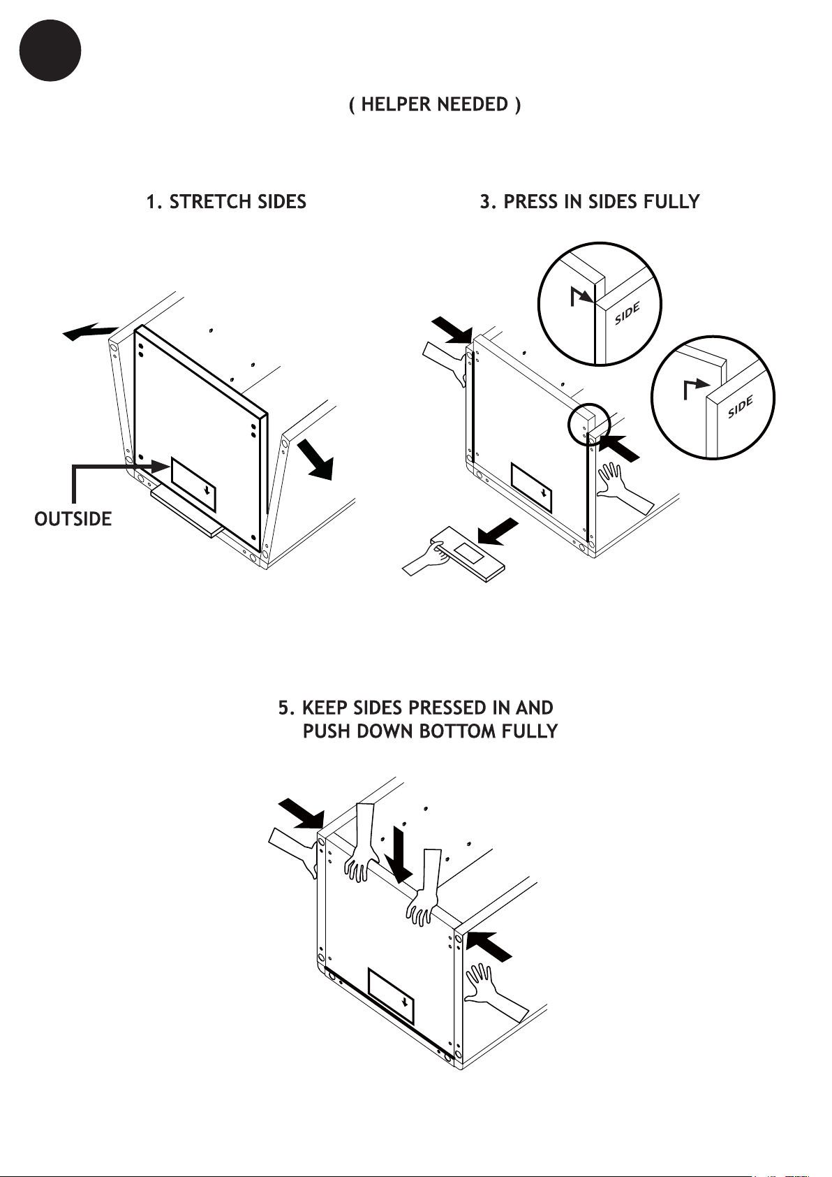
2
INSERT BOTTOM
TO INSERT BOTTOM
OK
BOTTOM
2. REST BOTTOM ON SPACER
PRESS
BOTTOM
4. PULL OUT SPACER
NO
BOTTOM
PRESS
~ 5 ~
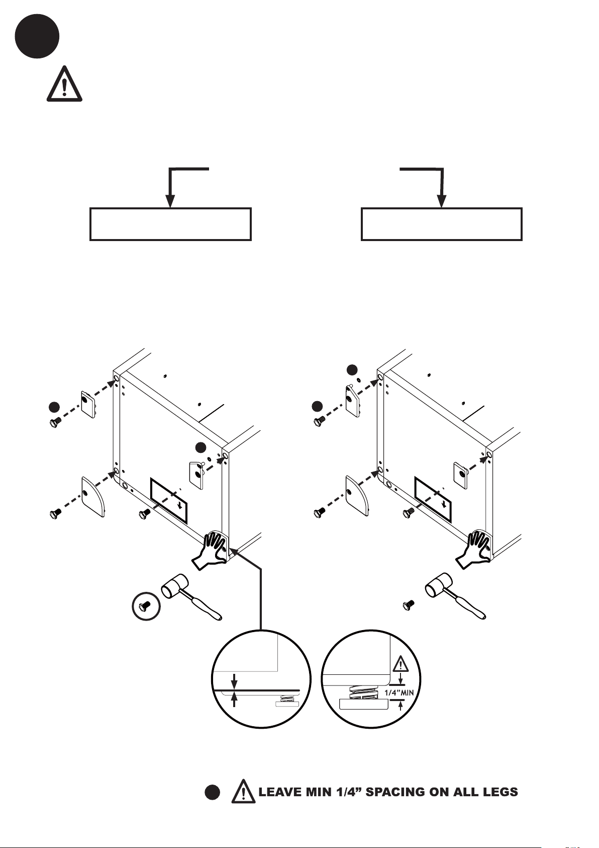
3
INSTALL BOTTOM CONNECTOR PLATES
WARNING! Connector plates can be removed ONLY as described on page 14.
HAND PRESS IN BOTTOM REAR CONNECTOR PLATES
CHOOSE WHICH SIDE TO PLACE THE HINGE, RIGHT OR LEFT
CHOOSE HINGE POSITION
INSERT:
B
LEGS
HINGE ON RIGHT
HINGE 1
BOTTOM LEFT
FRONT CONNECTOR
LEFT
BOTTOM
LEFT
FRONT
BOTTOM
LEFT
REAR
BOTTOM
BOTTOM
OUTSIDE
WASHER
HINGE 1
BACK
HINGE ON LEFT
INSERT:
WASHER
A
B
HINGE 2
LEGS
A
RIGHT
BOTTOM
LEFT
REAR
HINGE 2
BOTTOM RIGHT
FRONT CONNECTOR
LEFT
BOTTOM
BOTTOM
OUTSIDE
BACK
BOTTOM
RIGHT
FRONT
RIGHT
BOTTOM
RIGHT
REAR
TAP
GENTLY
BOTTOM
RIGHT
REAR
TAP
GENTLY
NO GAP!
TAP IN CONNECTORS TIGHTLY (NO GAP) WITH CLOSED HAND OR RUBBER MALLET
SCREW IN ALL LEGS
B
~ 6 ~
 Loading...