

Vintage Cellars Platinum MIni Split User Manual

Platinum Split
TECH MANUAL
FOR SYSTEMS EQUIPPED WITH:
WATER COOLED CONDENSING UNIT
The Coolest Thing In Wine Storage
PSWC 033114

We manufacture, test and certify 100% of our wine cooling units in
the USA. By sourcing the best components and closely controlling our
manufacturing processes, we can assure the highest-quality,
lowest defect manufacturing rates in the industry.
Copyright © 2012. WhisperKOOL. All rights reserved.
WhisperKOOL copyrights this manual, the product design, and the design concepts, with all rights reserved. Your rights with
regard to the hardware and manual are subject to the restrictions and limitations imposed by the copyright laws of the USA.
Under copyright laws, this manual may not be copied, reproduced, translated, transmitted, or reduced to any printed or electronic
medium or to any machine-readable form, for any purpose, in whole or in part, without the written consent of WhisperKOOL.
Every eort has been made to ensure that the information in this manual is accurate. WhisperKOOL is not responsible for printing
or clerical errors.
WhisperKOOL reserves the right to make corrections or improvements to the information provided and to the related hardware at
any time, without notice.
Vinothèque and WhisperKOOL are registered trademarks, and ECE is a trademark of WhisperKOOL. All rights reserved.
Mention of third-party products is for informational purposes only and constitutes neither an endorsement nor a
recommendation. WhisperKOOL assumes no liability with regard to the performance or use of these products.
REV 02
PSWC 033114

TABLE OF CONTENTS
Quick Reference Guide
Evaporator Unit ..........................................
Controller Layout & Specications ........................
Fully Ducted Unit & Specications ........................
2
3
4
Receiving & Inspecting The System .........................
Before You Start ............................................
Preparing the Wine Cellar ...................................
Preparing the Evaporator Unit ..............................
Installing the Evaporator Unit ..............................
Drain Line ...................................................
Liquid Measuring Thermostat (Bottle Probe) ...............
Installing the Fully Ducted Evaporator Unit ................
Remote Keypad .............................................
Platinum Split Wiring Diagram .............................
Platinum Split with Humidity Wiring Diagram ..............
Condensing Unit Wiring Diagram ...........................
Active Humidity Option ....................................
Humidistat Installation .....................................
5
6
7
10
11
13
14
15
18
19
20
21
22
23
Preparing the Condensing Unit .............................
Quick Reference Guide: Condensing Unit ...................
Line Set Piping Diagrams ...................................
Installing the Condensing Unit .............................
Installing the Wall Mount Kit ...............................
Installing the Ducted Plenum ...............................
System Operation. . . . . . . . . . . . . . . . . . . . . . . . . . . . . . . . . . . . . . . . . . .
Controller Functions ........................................
Maintenance Schedule .....................................
Troubleshooting Guide .....................................
Bypass Test Procedure ......................................
Technical Assistance & Accessories .........................
25
26
27
28
31
32
33
34
37
38
40
41
www.whisperkool.com | Page 1
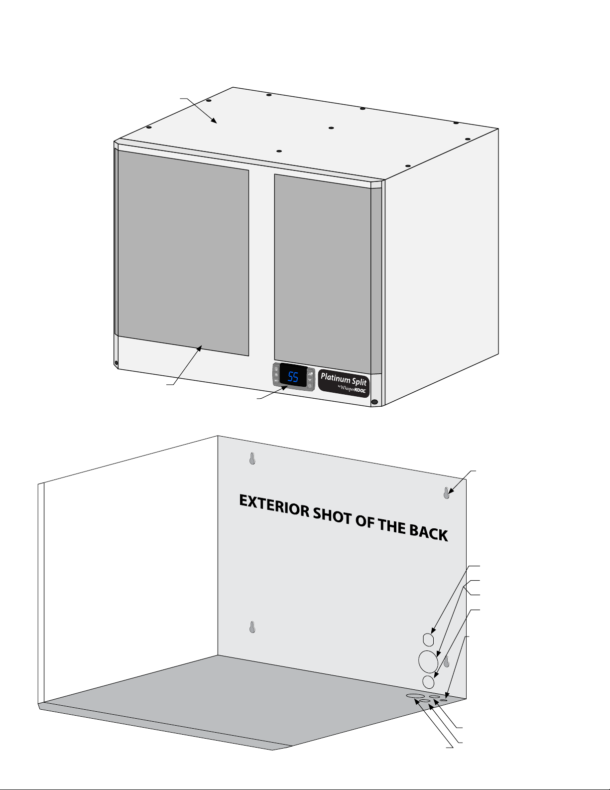
Platinum Split Evaporator Unit (Fan Coil Unit) Front / Side View
Evaporator Unit (Fan Coil Unit)
QUICK REFERENCE GUIDE
°
Filter Grille
Controller
F
Platinum Split Evaporator Unit (Fan Coil Unit) Rear / Side View
Mounting Key Hole (X4)
THROUGH THE WALL
Option 1
Knock Out For Wiring
Knock Out For Suction Line
Knock Out For Liquid Line
Knock Out For Drain Line
Circular Connection
Mounting Location
Page 2 | 1-800-343-9463
Liquid Line Knock Out
Suction Line Knock Out
INSIDE CELLAR
Option 2
Knock Out For Drain Line
Knock Out For Wiring
PSWC 033114
QUICK REFERENCE GUIDE
°
F
°
F
°
F
°
F
°
F
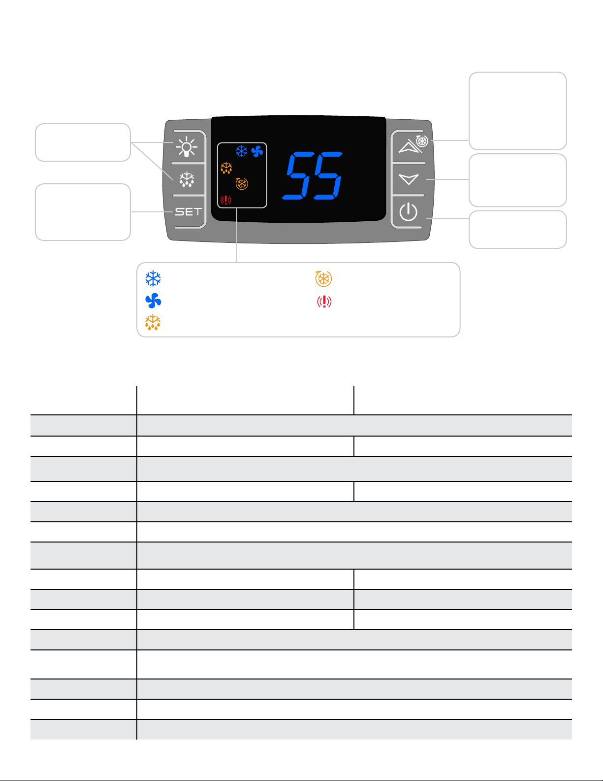
Controller Layout
Inactive
View Set Point
Change Set Point
(Press and hold 3-5 sec)
Refer to page 34 for complete listing of buttons and symbols.
°
F
Compressor On
Fans are On
Unit is in Pre-Chill Mode
Alarm is Present
Unit is in Anti-Frost Mode
High History
Scroll Button
Cellar Pre-Chill
(Press and hold 3-5 sec)
Low History
Scroll Button
Power On/O
WALL MOUNTED PLATINUM SPLIT UNIT SPECIFICATIONS
Model
4000 Evaporator
(Fan Coil Unit)
(Water Cooled Condensing Unit)
Cellar Size (cu. ft.) 1000
Dimensions 20.5”w x 15.625”h x 16”d 13”w x 10”h x 18.5”d
BTUh with 90° air entering
the Condenser Coil
CFM
270 N/A
3650
Refrigerant R-134a
Condensing Unit HP 1/3++
Voltage Rating
dedicated circuit required)
Weight (lbs) 56 44
AMPS
(20 amp
(Starting/Running) 2/1 32.7/7.2
115V
dBA 54 50
Drainline 1/2” Condensate
Installation
Evaporator Unit (Fan Coil Unit) is installed in the cellar or up to 25 ducted ft. away, condenser is
installed up to 100 ft from Evaporator Unit (Fan Coil Unit)
4000 Condenser
Thermostat Digital Control Display
Temp. Delta 55°F
Temperature dierential between the cellar temperature and condenser air intake temperature.
Warranty 2 year parts and labor
www.whisperkool.com | Page 3
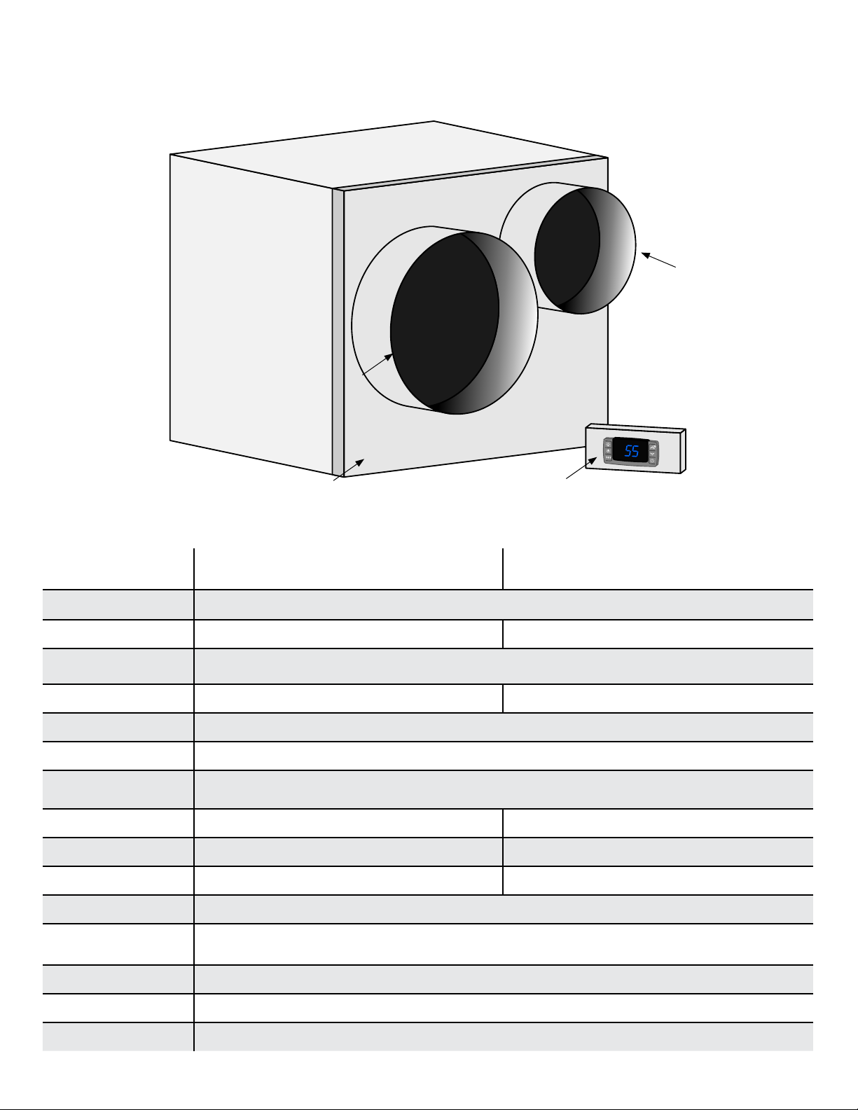
QUICK REFERENCE GUIDE
Platinum Split Evaporator Unit (Fan Coil Unit) Front / Side View
Supply Air
Return Air
°
F
Duct Plenum
Keypad
DUCTED PLATINUM SPLIT UNIT SPECIFICATIONS
Model
4000 Evaporator
(Fan Coil Unit)
(Water Cooled Condensing Unit)
Cellar Size (cu. ft.) 1000
Dimensions 20.5”w x 15.625”h x 20”d 13”w x 10”h x 18.5”d
BTUh with 90° air entering
the Condenser Coil
CFM
270 N/A
3650
Refrigerant R-134a
Condensing Unit HP 1/3++
Voltage Rating
dedicated circuit required)
(20 amp
115V
Weight (lbs) 56 44
AMPS
(Starting/Running) 2/1 32.7/7.2
dBA 54 50
4000 Condenser
Drainline 1/2” Condensate
Installation
Use 8” supply and 10” return insulated ducting. Ducting should not exceed 25 ft. from the
cellar. Condenser is installed up to 100 ft from Evaporator Unit (Fan Coil Unit)
Thermostat Digital Control Display
Temp. Delta 55°F
Temperature dierential between the cellar temperature and condenser air intake temperature.
Warranty 2 year parts and labor
Page 4 | 1-800-343-9463
PSWC 033114
RECEIVING & INSPECTING THE SYSTEM
Receiving and Inspecting the System
• Lift only at the designated hand hold locations on the shipping container or fully support the unit from
underneath. A shipment may include one or more boxes containing accessories.
• Before opening the container, inspect the packaging for any obvious signs of damage or mishandling.
• Write any discrepancy or visual damage on the Bill of Lading before signing.
• Allow the condensing unit to sit for 24 hours prior to start up. The condensing unit can be placed in the
installation location, piped and evacuated during this time.
Note: WhisperKOOL units are manufactured in the USA and tested prior to shipment.
Review the Packing Slip to Verify Contents
• Check the model number to ensure it is correct.
• Check that all factory options ordered are listed.
If any items listed on the packing slip do not match your order information,
contact WhisperKOOL Customer Service immediately.
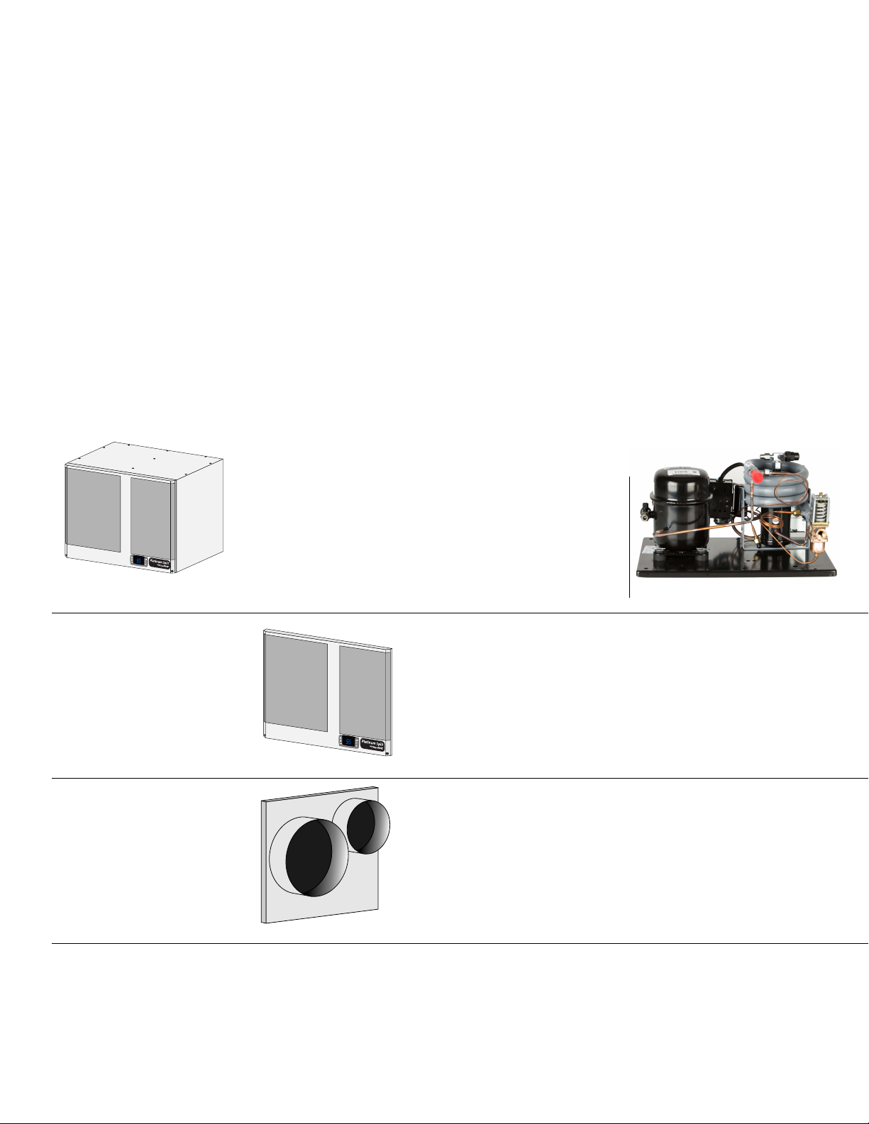
Check the Box for the following contents:
Main Evaporator Box
°
F
(1) Platinum Split Evaporator Unit
(Fan Coil Unit)
Wall-Mount Accessory Kit
Ducted Accessory Kit
(1) Installation Kit which includes:
(2) ½” 90° Barb ttings
(1) ½” barb tee
(1) 10 ft. 1/2” Drain Line
(4) 1 ¾” hex head screws
(1) Bypass plug
°
F
(1) Filter Grille
(2) Cable tie mounts and cable ties
(1) Black Strain relief
(1) 1/4” sight glass
(1) 1/4” lter drier
Main Condensing Unit Box
(1) Condensing Unit
(1) Platinum Split Tech Manual
(1) Platinum Split Owners Manual
(1) Split System Warranty Checklist
(1) 12 ft. Bottle Probe
(10) 6-32 3/8” Phillips Pan Head Screw
(1) Display Adapter
(1) Platinum Split Tech Manual
(1) Platinum Split Owners Manual
(1) Split System Warranty Checklist
(1) 50 ft. Bottle Probe
(1) Remote Keypad
(1) 50 ft. Keypad Communication Cable
(1) Duct Plenum
Please leave the unit in its original box until you are ready for installation. This will allow you to move the product
safely without damaging it. When you are ready to remove the product from the box, refer to the installation
instructions.
TIP: Save your box and all packaging materials. They provide the only safe means of transporting/shipping the unit.
www.whisperkool.com | Page 5

BEFORE YOU START
1. Inspect all components prior to installation. If damage is found, please contact your distributor or WhisperKOOL
Customer Service at 1.800.343.9463.
2. The Condensing Unit requires a dedicated 115-volt 20-amp circuit. Use a surge protector with the unit. Do not
use a GFI (Ground Fault Interrupter) line.
3. It is REQUIRED to install a drain line to remove condensation from the Evaporator Unit (Fan Coil Unit).
4. The system is intended for use in properly designed and constructed wine cellars. Hire a professional wine
storage consultant with a valid contractor’s license to build your wine cellar.
5. WhisperKOOL requires that all Split Systems are installed by a certified HVAC-R technician only, Nate or equivalent is
recommended.
6. Warranty is not active until a Warranty Checklist has been received, reviewed, and approved.
If you encounter a problem with your WhisperKOOL system, please refer to the Troubleshooting Guide on page 16.
If you have any further questions, concerns, or need assistance, please contact WhisperKOOL’s Customer Service at
1.800.343.9463. Please be sure all testing has been completed prior to contacting Customer Service. Please have your
results ready for your representative.
Page 6 | 1-800-343-9463
PSWC 033114

PREPARING THE WINE CELLAR
The performance and life of your system is contingent upon the
steps you take in preparing the wine cellar.
Note: Improperly preparing your enclosure or incorrectly installing your
unit may cause unit failure, leaking of condensation, and other negative side eects.
IT IS HIGHLY RECOMMENDED THAT YOU OBTAIN THE ASSISTANCE
OF A WINE STORAGE PROFESSIONAL.
Wine storage professionals work with licensed contractors, refrigeration technicians, and racking companies to build
well-insulated, beautiful, and protective wine cellars. WhisperKOOL has put together some useful tips to assist in the
installation process. Our recommendations are meant to act as a guide in the process of building a proper enclosure.
Your intended location may have specic needs that we do not address.
Wall & Ceiling Framing
Build wine cellar walls using standard 2x4 or 2x6 construction methods and ceiling joists following the guidelines of
local and state codes in your area. As a general rule, the thicker the walls and the higher the insulation value in your
cellar, the better it will be at maintaining a consistent temperature.
Insulation
Insulation is REQUIRED with the use of the WhisperKOOL product. Standard berglass or rigid foam insulation is
normally used in cellar construction or, in some cases, “blown-in” insulation is used. It is very important that all walls
and ceilings are insulated to keep the cellar temperature as consistent as possible during the summer and winter
months. The R-value, or quality of insulation, is determined by the rate at which heat passes through the insulation.
The higher the R-value, the more resistant the insulation is to conducting heat. Using higher R-values in insulation will
lower your operating costs and unit run time. (R-13 minimum, R-19 recommended, R-30 for ceiling and exterior walls.)
Vapor Barrier
Water vapor creates its own pressure, separate from the air pressure, and will intrude into colder/drier areas. A vapor
barrier is REQUIRED to prevent the intrusion of water vapor so that the cellar can be kept at the correct temperature
and humidity. 6 mm plastic sheeting (recommended) should be applied to the warm side of the cellar walls. The
vapor barrier must also be applied to the outside walls and ceiling. If it is impossible to reach the outside, then the
plastic must be applied from within the cellar. The most common method is to wrap the entire interior, leaving the
plastic loose in the stud cavity so the insulation can be placed between each stud. All of the walls and ceiling must be
wrapped in plastic for a complete vapor barrier.
In areas of high humidity, such as Southern and Gulf States, the vapor barrier will prevent inltration of warm moist
air. The moist air can cause mold to form, and standing water in drain pans promote microbial and fungal growth that
cause unpleasant odors and indoor air quality problems. If mold is found, remove it immediately and sanitize that
portion of the unit. Note: High humidity signicantly increases the heat load on the cooling system.
Any break in the vapor barriers (cut, nail hole, over-lapping, etc) will allow a moisture leak and must be sealed. Electric
conduit is a “duct” for vapor to travel in. The conduit should be caulked and sealed on the warm air end.
www.whisperkool.com | Page 7
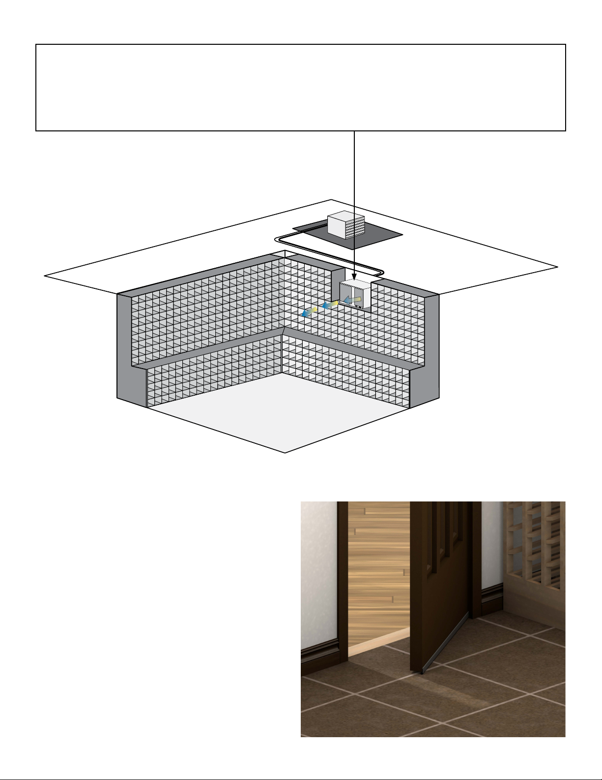
Mounting the Unit
The evaporator unit must be mounted within 18“ of the top of the room in order to achieve sucient cooling.
As the room cools down, the warm air will rise to the ceiling. Mounting the unit high in the room will create a
consistently cool environment by capturing the warm air and replacing it with cool air. Mounting the unit low in
the room will result in a temperature variation in the room due to the unit’s inability to draw warm air from the
ceiling of the cellar to the unit itself, and cold air settling to the oor.
Wine Cellar
Door and Door Seal
An exterior grade (1 3/4”) door must be installed as a
cellar door. It is very important that weather stripping is
attached to all 4 sides of the doorjamb. A bottom “sweep”
or threshold is also required. The door must have a very
good seal to keep the cool cellar air from escaping out
of the cellar. One of the most common problems with
cooling systems running continually is due to the door not
sealing properly. In cases where glass doors are used
and the room size is close to the recommended system
size, the next larger size WhisperKOOL system should
be used. This will compensate for the insulation loss due
to the lower insulating rating of glass.
Page 8 | 1-800-343-9463
PSWC 033114
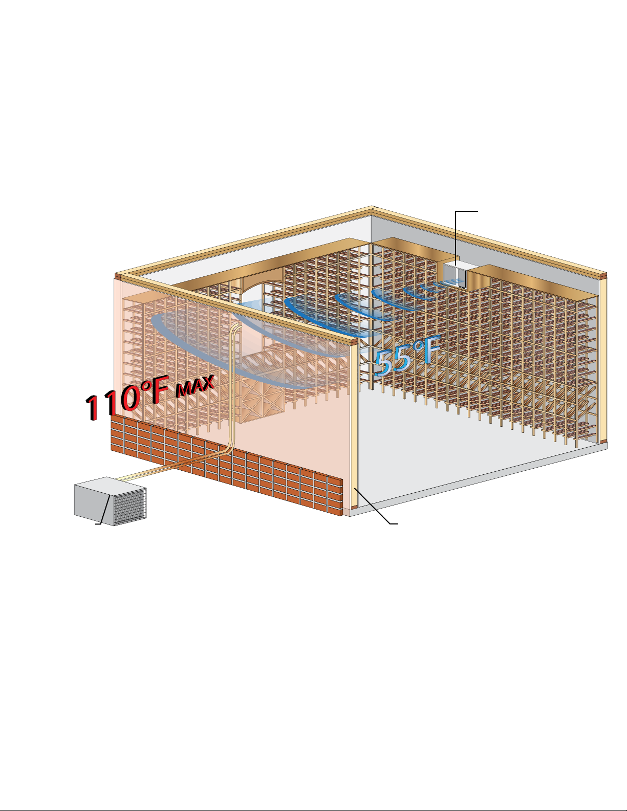
Ventilation
The necessity of dissipating heat away from the condensing unit is critical to the performance and cannot be
overstated. As the system operates and cools, a greater amount of heat is generated on the condensing side of the
system. Adequate ventilation is required in order to dissipate heat away from the condensing unit. If ventilation is
inadequate, the exhaust will heat up the area or room and adversely aect the systems ability to cool. In some cases, it
may be advisable to install a vent fan to dissipate heat within the exhaust area on the condensing side of the system.
However, you must have a fresh air inlet as well.
Note: If you are unsure about having adequate ventilation in your install location, please
contact us to assess your specic installation at support@whisperkool.com or 1.800.343.9463.
Evaporator Unit
(Fan Coil Unit)
BACK - EXHAUST SIDE
FRONT - WINE CELLAR
Condensing Unit
Exterior Cellar Wall
Ambient Temperature Factor
The cooling system has the ability to cool a wine cellar eciently to 55°F as long as the ambient temperature of the
area that it is exhausting to does not exceed 110°F. Therefore, you want to exhaust the condensing unit in a space which
will not exceed 110°F. Otherwise the system will not have the capacity to keep the wine at a desirable 55°F.
Warning, allowing your system to operate in high ambient temperatures for
extended periods of time will greatly decrease the life of your system and void
your warranty. The cooler the temperature of the air entering the condenser coil
the more cooling capacity the system has. The less heat gain through the common
wall, the less the electricity consumption.
www.whisperkool.com | Page 9
WALL MOUNT EVAPORATOR UNIT (FAN COIL UNIT)
Required Tools:
• Drill
• 5/32” Drill Bit
• 1/4” Socket Drill Bit
PREPARING AND INSTALLING THE
• 1/4” Wrench
• Phillips Head Screwdriver
• Tape Measure
• Brazing Torch
• Drywall Saw
• Ladder
• Level
• Pliers
• Pencil
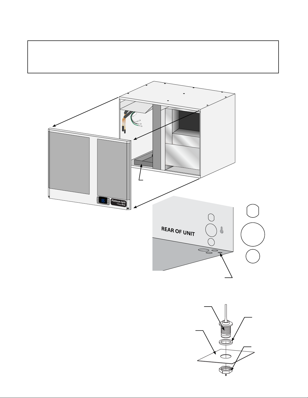
°
F
1. Remove the knockouts for the drain line,
line set, and electrical on the bottom or rear
of the unit depending on your installation
preference.
2. Remove the knockout on the bottom of the
unit for the bottle probe connector
3. Remove the insulation from the knockout
holes.
4. Remove the nut from the bottle probe
connector.
5. Insert the bottle probe connector through
the knockout.
6. Secure the bottle probe connector to the
wrapper with the nut removed in step 4.
7. For ease of installation, remove the 9 screws
securing the top and remove the top.
DRAIN PAN
Power
3/8” Suction
1/4” Liquid
Drain
HOLE FOR CIRCULAR CONNECTOR
(BOTTLE PROBE INPUT)
CIRCULAR CONNECTOR/
BOTTLE PROBE INPUT
RUBBER WASHER
UNIT PANEL
Page 10 | 1-800-343-9463
NUT
PSWC 033114
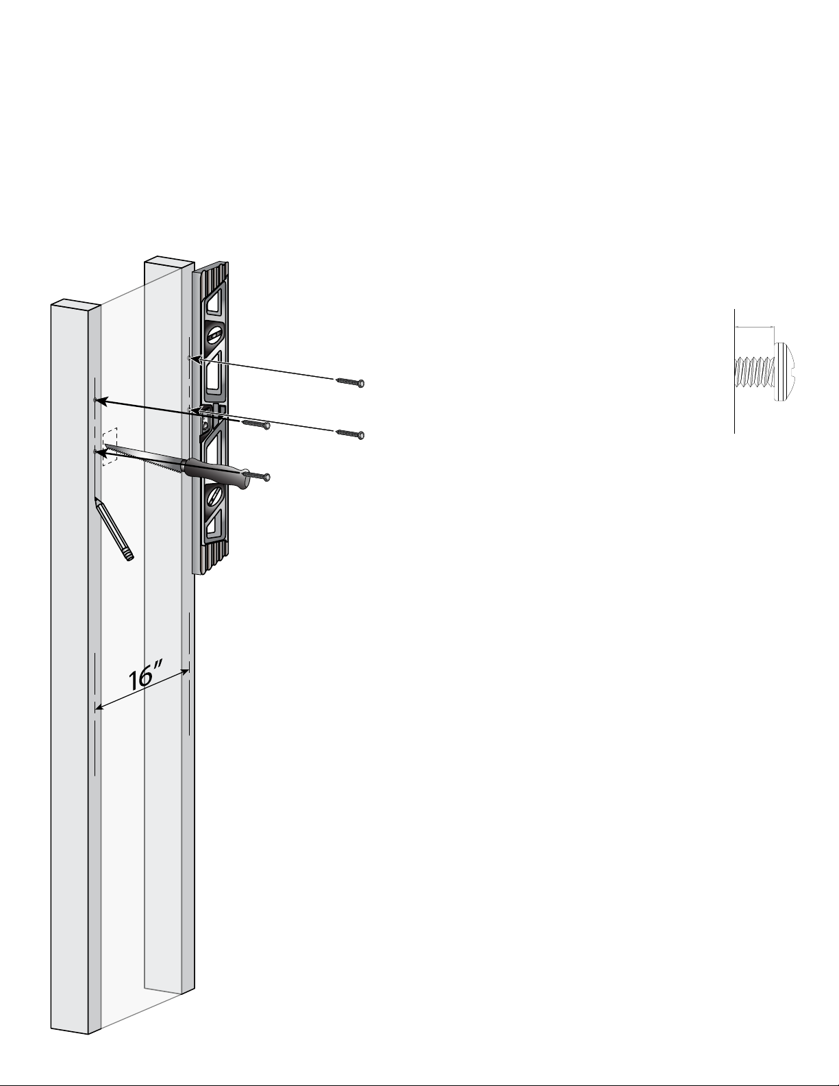
INSTALLING THE WALL MOUNTED EVAPORATOR (FAN COIL UNIT)
1. Locate 2 wall studs in the desired mounting location spaced 16” on center.
2. Mark vertical lines on each stud 16” apart.
3. Mark an intersecting, horizontal line at the desired height of the unit.
4. Make a mark on each stud 13 ½” down from the intersection of the horizontal and vertical lines.
Note: The top of the unit needs to be installed at a
minimum of 6” and a maximum of 18” from the ceiling.
5. Install the 4 supplied 1 ¾” hex
head screws into the studs at the
locations marked leaving 1/8”
between the wall surface and screw
head.
WALL
STUD
1/8”
6. If routing through a wall, cut out an access hole for
the line set, drain line and electrical.
7. Raise the evaporator to the installation location. Align
the rear key holes with the mounting screws and
mount the unit.
8. Using a ¼” wrench or socket, tighten the top
mounting screws.
www.whisperkool.com | Page 11
INSTALLING THE WALL MOUNTED EVAPORATOR (FAN COIL UNIT)
9. Using 1/4” and 1/2” copper tubing, route the liquid and
suction lines through the knockouts in the wrapper. Be sure
to extend the tubing far enough outside of the wrapper
to extend through the wall if necessary. Note: ½” copper
tubing will slip over the 3/8” suction line on the evaporator
for an easy connection.
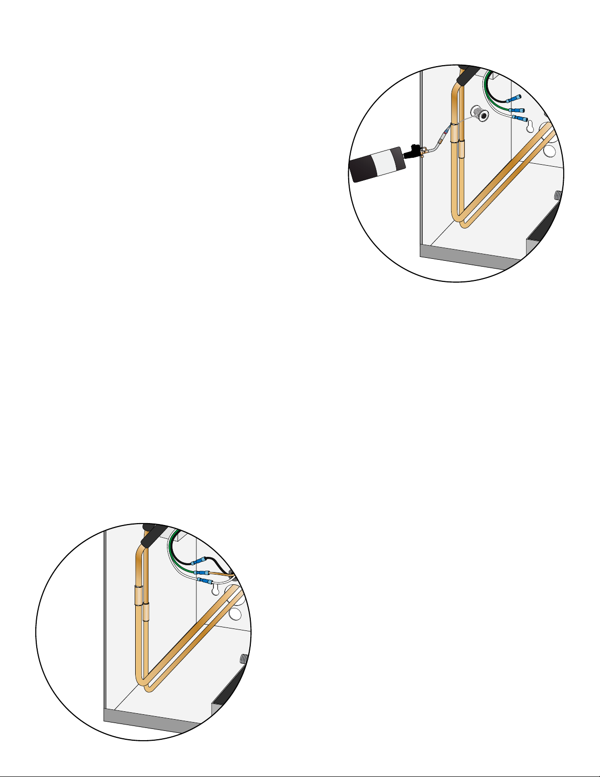
10. Remove the solenoid coil and wrap the solenoid valve with
a wet rag to prevent overheating.
11. To prevent oxidation, purge nitrogen through the system.
12. Braze the copper tubing to the connections on the
evaporator unit.
13. Insulate the suction line using Armaex or similar insulation.
14. Cut a short piece of ½” drain line and connect a ½” barb 90
to the drain line.
15. Route the drain line out of the wrapper through the hole for the drain line. Use the second barb 90 if
going through the bottom of the wrapper. Be sure to extend the tubing far enough outside the wrapper
to extend through the wall if necessary.
16. Using the cable ties and cable tie mounts provided, secure the drain line to the bottom of the wrapper to
ensure a downward slope.
17. If you have purchased the Active Humidity Option, route the ¼” water line out of the evaporator unit
with the line set.
18. Route the power supply wires into the unit through the knockout.
19. Remove the wire nuts from the black, white and green wires located in the lower left corner of the
evaporator unit.
20. Following the supplied wiring diagram, connect the power supply wires to the black, white and green
wires using the supplied wire nuts (Hot=Black, Neutral=White, Ground= Green).
21. Install the supplied black strain relief to secure the power supply wires in the housing.
22. Route the display adapter through the grommet below
the drip dray and into the blower compartment.
23. Connect the display adapter to the circular connector for
the display located in the lower left corner of the housing.
24. If the unit was equipped with the Active Humidity Option,
route the communication cable from the desired control
mounting location into the evaporator unit.
25. Connect the communication cable to the circular
connector located in the lower left corner of the housing.
Page 12 | 1-800-343-9463
26. Secure all wiring neatly and close to the left wall to
minimize obstructing the airow.
27. Attach the supplied bottle probe to the circular connector
on the bottom of the unit. Follow the directions on page
13 for correct installation and placement of the bottle
probe.
PSWC 033114
 Loading...