

Page 1
1738 E. Alpine Ave. Stockton, CA 95205
Remove cardboard
insert.
Safety Switch
(Low Voltage ClassII)
WhisperKOOL
1(800) 343-9463
www.whisperkool.com
3. Mounting the pump: the tank has two slots provided to mount the unit.
The slots are located on the ends of the tank (Figure 5). The unit should
be mounted either on the side of the air conditioner unit or nearby wall.
Pump must be level and the inlet must be below the coil drain. Conduit
ttings are not compatible with the plastic pump housing.
4. The pump should not be installed in a manner that will subject it to
splashing or spraying.
5. This pump is not intended for use inside air plenums.
INTRODUCTION
The condensate pump kit is designed as an automatic condensate removal
pump for water dripping o an air conditioner evaporative coil. The pump is
controlled by a oat/switch mechanism that turns the pump on when approximately 2-1/4” of water collects in the tank, and automatically switches o when
the tank drains to approximately 1-1/4”.
The pumps are carefully packaged, inspected and tested to insure safe
operation and delivery. When you receive your pump, examine it carefully to
determine that there are no broken or damaged parts that may have occurred
during shipment. If damage has occurred, make notation and notify WhisperKool. They will assist you in replacement or repair, if required.
READ INSTRUCTIONS CAREFULLY BEFORE ATTEMPTING TO INSTALL, OPERATE
OR SERVICE THE LITTLE GIANT PUMP. KNOW THE PUMP APPLICATION, LIMITATIONS AND POTENTIAL HAZARDS. PROTECT YOURSELF AND OTHERS BY OBSERVING ALL SAFETY INFORMATION. FAILURE TO COMPLY WITH INSTRUCTIONS
COULD RESULT IN PERSONAL INJURY AND/OR PROPERTY DAMAGE! RETAIN
INSTRUCTIONS FOR FUTURE REFERENCE. INSTALLATION AND CONNECTIONS
ARE TO BE MADE BY A QUALIFIED PERSON.
WARNING
SAFETY GUIDELINE
DO NOT USE TO PUMP FLAMMABLE OR EXPLOSIVE FLUIDS SUCH AS GASOLINE, FUEL OIL, KEROSENE, ETC. DO NOT USE IN EXPLOSIVE ATMOSPHERES.
PUMP SHOULD BE USED WITH LIQUIDS COMPATIBLE WITH PUMP COMPONENT
MATERIALS.
DO NOT HANDLE PUMP WITH WET HANDS OR WHEN STANDING ON A WET OR
DAMP SURFACE, OR IN WATER. THIS PUMP IS SUPPLIED WITH A GROUNDING
CONDUCTOR AND/OR GROUNDING TYPE ATTACHMENT PLUG. TO REDUCE THE
RISK OF ELECTRICAL SHOCK, BE CERTAIN THAT IT IS CONNECTED TO A PROPERLY GROUNDED GROUNDING TYPE RECEPTACLE.
IN ANY INSTALLATIONS WHERE PROPERTY DAMAGE AND/OR PERSONAL
INJURY MIGHT RESULT FROM AN INOPERATIVE OR
LEAKING PUMP DUE TO POWER OUTAGES, DISCHARGE LINE
BLOCKAGE, OR ANY OTHER REASON, A BACKUP SYSTEM(S) AND/OR ALARM
SHOULD BE USED.
SUPPORT PUMP AND PIPING WHEN ASSEMBLING AND WHEN INSTALLED. FAILURE TO DO SO MAY CAUSE PIPING TO BREAK, PUMP TO FAIL, MOTOR BEARING
FAILURES, ETC.
!!
ELECTRICAL CONNECTIONS
WARNING
1. Shut o electrical power at fuse box before making any connections. All
wiring must comply with local codes.
2. Line voltage: Connect power cord to line voltage specied on motor and
nameplate. Power cord must be connected to a constant source of power
(not a fan or other device that runs intermittently). If power cord does not
have a plug, wiring is as follows: green (or green/yellow)—ground. Black
(or brown)— line. White (or blue)—neutral.
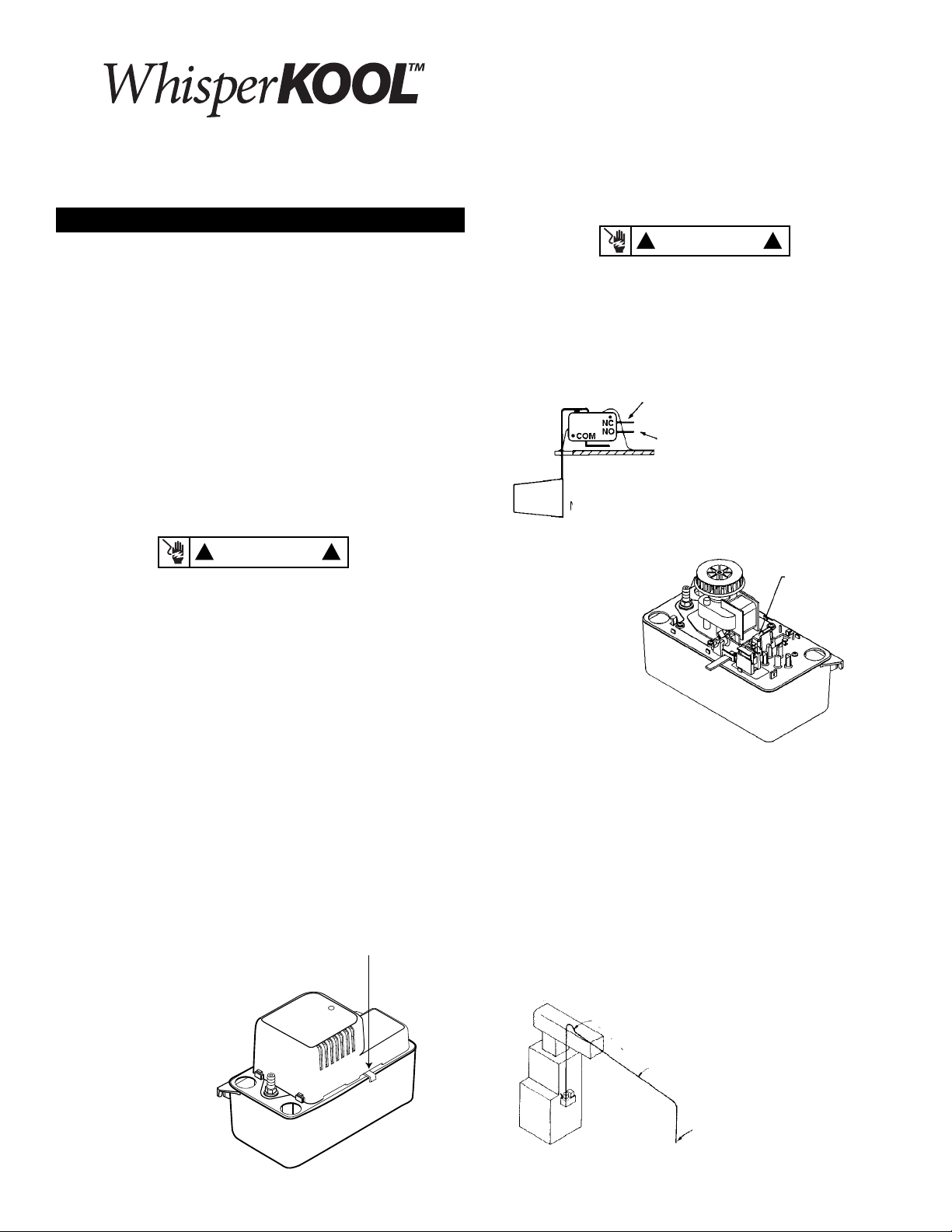
Connect here to turn alarm on.
Connect here to turn thermostat o.
NOTE: All wiring to be done by qualied service
technician. Refer to local codes in your area.
3. Safety switch: The
safety overow switch
should be connected
to a class II low voltage circuit. To control
a thermostatic circuit
the COM and NO
connections from the
safety switch are to be
wired in series with
the low voltage thermostat circuit to shut
down the heating/AC
circuit. The COM and
NC switch contacts
may be used to actuate a low voltage alarm circuit (connected in series)
if the heating/cooling system can not be disrupted. The safety switch
comes from the factory with leads connected to the COM and NO switch
terminals. Typical hook-up of “NC” circuits would be (Figures 2 & 3).
4. If fused plug is used on 230V units, a 1.0 amp fuse is recommended.
!!
1. Before installing pump,
allow air conditioner
to cycle several times,
collecting condensate in
a separate container to
help ush any residual
oils that may remain in
the system.
2. Carefully unpack the
pump. Remove the
cardboard packing from
the motor cover air
slots. Carefully slide the
packing away from the
pump. This packing is
used to prevent switch
movement during shipment (Figure 1).
INSTALLATION
PIPING
1. Run exible tubing or pipe from evaporator drain into one of the three
pump inlets. Be sure inlet piping is sloped downward to allow gravity
ow (Figure 4). Extend the inlet piping into the tank from 1 to 3 inches to
ensure that it will not interfere with proper oat operation. Be sure that
the inlet piping is cut at an angle where it enters the tank.
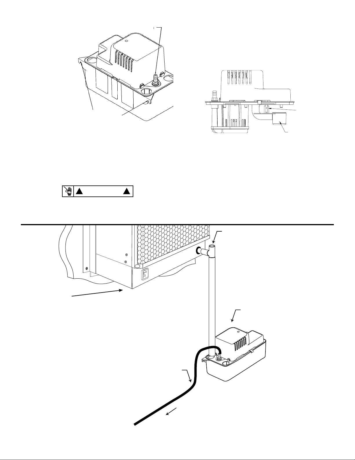
Discharge Line Installation
Inverted “U” Trap
Slope down from highest point
Drop to bottom of pump
or below if possible
Page 2
Pump Mounted to Wall
Extreme is for Example Only
2. The outlet piping
Safety switch oat
should be exible
tubing secured with
a hose clamp (not
provided) or pipe (3/8
inch I.D. maximum
to prevent excessive
ow back to unit).
From condensate unit,
extend discharge piping straight up as high
as necessary. Do not
extend this line above
the head/GPH of
the particular model
being installed. From
this high point, slope
discharge line down
slightly to a point
above drain area; then
turn down and extend
to a point below or approximately level with the bottom of the condensate unit. This will give a siphoning eect which will improve eciency
of the condensate unit and will, in most cases, eliminate the need for a
check valve (Figure 5). If it is not possible to slope discharge line down,
make an inverted “U” trap directly above the pump at the highest point.
Mounting Slots
Check Value
SERVICE INSTRUCTIONS
WARNING
1. Make certain that the unit is disconnected from the power source before
attempting to service or remove any component!
!!
2. Be sure the oats move freely. Clean as necessary (Figure 6).
3. Clean the tank with warm water and mild soap.
4. Check the inlet and outlet piping. Clean as necessary. Be sure there are no
kinks in the line that would inhibit ow.
TESTING
Motor switch oat
1. Turn on power.
2. Remove motor/tank cover assembly and hold level.
3. Test motor switch by raising motor switch oat with nger (Figure 6). Motor should turn on just before oat contacts cover.
4. Test safety switch by raising safety switch oat with nger. Safety switch
should activate before oat contacts cover.
5. Replace motor/tank cover assembly on tank. This pump is suitable for
gas furnace condensate applications. Caution must be taken to ensure
acidity of condensate does not increase below the average pH of 3.4 (to
prevent localized pocket of acid that acts like a battery causing pitting) by
routinely cleaning or ushing tank with fresh water.
Cooling System
Drain Line
Drain Line
To: Garden
Sink
Sewer
Potted Plant
 Loading...