

Vinson Acoustics VA IC65, VA IW6, Contractor Series, VA IC6EC Quick Start Manual

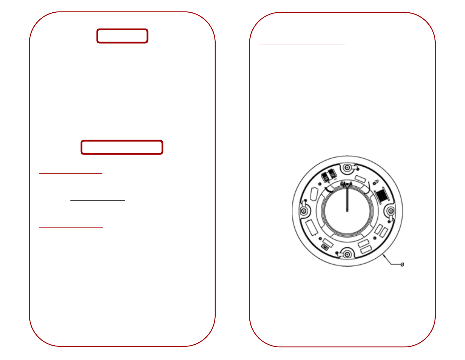
Mounting the Speaker
• Remove the grille to expose the mounting screws.
• Be sure the mounting tabs are turned in, allowing the speaker to fit
into the hole. Then insert the speaker into the mounting hole.
• Use the four screws to tighten the mounting tabs to the wall or ceiling.
• Replace the grille.
• To remove the speaker from the wall or ceiling, loosen the screws only
far enough to remove the speaker. This will prevent loss of the
mounting tabs.
VA IC65
-4-
www.vinsonacoustics.com
6 ½ 2-Way In-Ceiling Speaker
www.vinsonacoustics.com
Specifications
• 6 ½” aluminum woofer and ¾” adjustable silk / titanium tweeter
• Frequency Response: 48Hz - 20KHz
• 48Hz +/- 20%Hz without baffle
• Power Handling: 80 - 120 watts @ 8 ohms
• Paintable white frame and perforated metal grille
• Magnet Size: 3.9" x 1.8" x .59"
• Magnet Weight: 16 oz
• Temperature range: 14°F-149°F
Installation Instructions
Choosing the Location:
• The mounting surface should be between 1.2" and 3.7" thick, and with at
least 3.7" clearance behind the mounting surface and no wall studs or
other objects to block the back of the speaker.
• Use the "speaker cutout template" to mark the location for mounting
the speaker.
Preparing the Speaker:
• If you want to paint the plastic frame & grille, paint them before
connecting the speaker wire or mounting the speaker.
• Use care when removing the speaker grilles from the micro-flange as
they fit very tightly. Excessive force may cause damage to the
speakers, grilles, and/or the speaker frame.
• When painting the frame, remove the grille and insert the supplied
cardboard paint mask to prevent the paint from entering the speaker.
-2-
www.vinsonacoustics.com
Connecting the Speaker Wires:
• Route the speaker wire from the receiver to the speaker.
• Separate about 4" of speaker wire at each conductor end.
• Using a wire stripper, remove about 6mm (1/4") of insulation from each
wire.
• Twist the ends of each wire to prevent fraying.
• Connect a marked wire to a red speaker terminal by pressing the
release tab, inserting the wire into the hole, and then releasing the tab.
Repeat this procedure to connect the unmarked wire to the black
terminal.
• Connect the marked wire coming from the speaker's red terminal to the
red or positive ( + ) terminal on the amplifier, then connect the
unmarked wire to the black or negative (-) terminal on the amplifier
-3-
www.vinsonacoustics.com
 Loading...