

Vinotemp Wine-Mate WM-8520HZD, Wine-Mate WM-3520HZD, Wine-Mate WM-4520HZD, Winemate WM-1500HZD, Winemate WM-2500HZD Installation, Use & Care Manual
...
wwwwww..wwiinneemmaattee..ccoomm
Wine Cooling System
WM-1520HZD, WM-2520HZD
WM-3520HZD, WM-4520HZD
WM-6520HZD, WM-8520HZD
Installation, Use & Care Manual
Read and save these instructions
wwwwww..vviinnootteemmpp..ccoomm
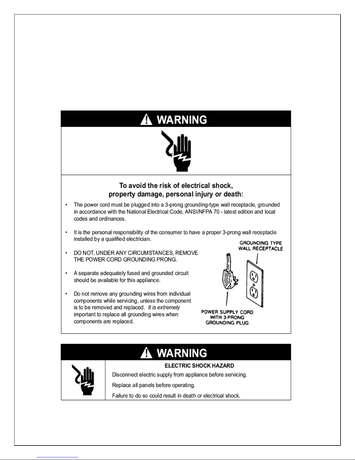
Important Safety Information
NOTES:
• Do not plug in until 24 hours after delivery.
• Do not use a ground fault interrupter (GFI).
• A dedicated 10 AMP circuit for WM-1520~2520HZD and 15 AMP for WM-
3520~8520HZD are required.
- 1 -

Table of Contents
Features & Specifications.…………………….……………..3
Installation Instructions……………..………………………..6
Temperature & Humidity…………………………..………..16
Care Guide…………………………………………………….20
Troubleshooting………….…………………………………..21
Electrical Diagrams………………..…………………….…24
Customer Support…….…………..…………………….…26
Warranty……………………………………………………….27
- 2 -
Features and Specifications
• HZD series cooling units are designed and used to provide a stable
temperature between 50~65 °F for a properly insulated space.
• The refrigerated space will maintain humidity ranges within 50~70% RH.
• These temperature and humidity ranges are optimized for long term
storage of wine.
• Temperature is controlled and humidity is adjusted using patented
technology.
• Horizontal cold-air supply is optimized for use in the wide cabinets or wine
rooms.
• The unit is self-contained ready for easy installation and use.
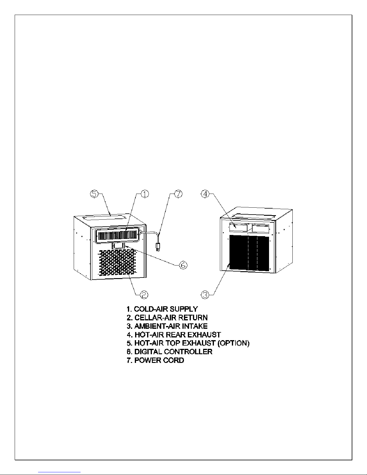
Fig. 1.1 WM-1520~2520HZD FEATURE DESCRIPTIONS
- 3 -
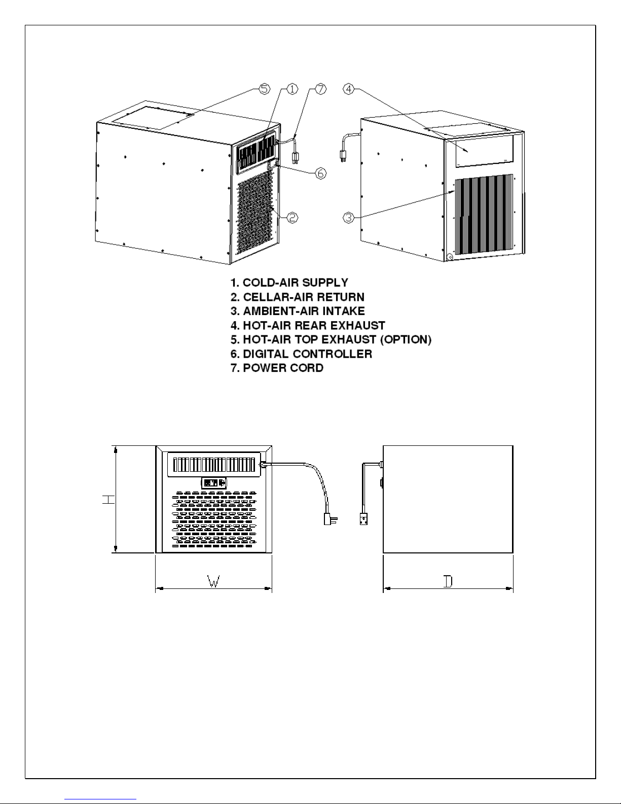
Fig. 1.2 WM-3520~8520HZD FEATURE DESCRIPTIONS
Fig. 1.3 WM-1520~2520HZD DIMENSIONS
- 4 -
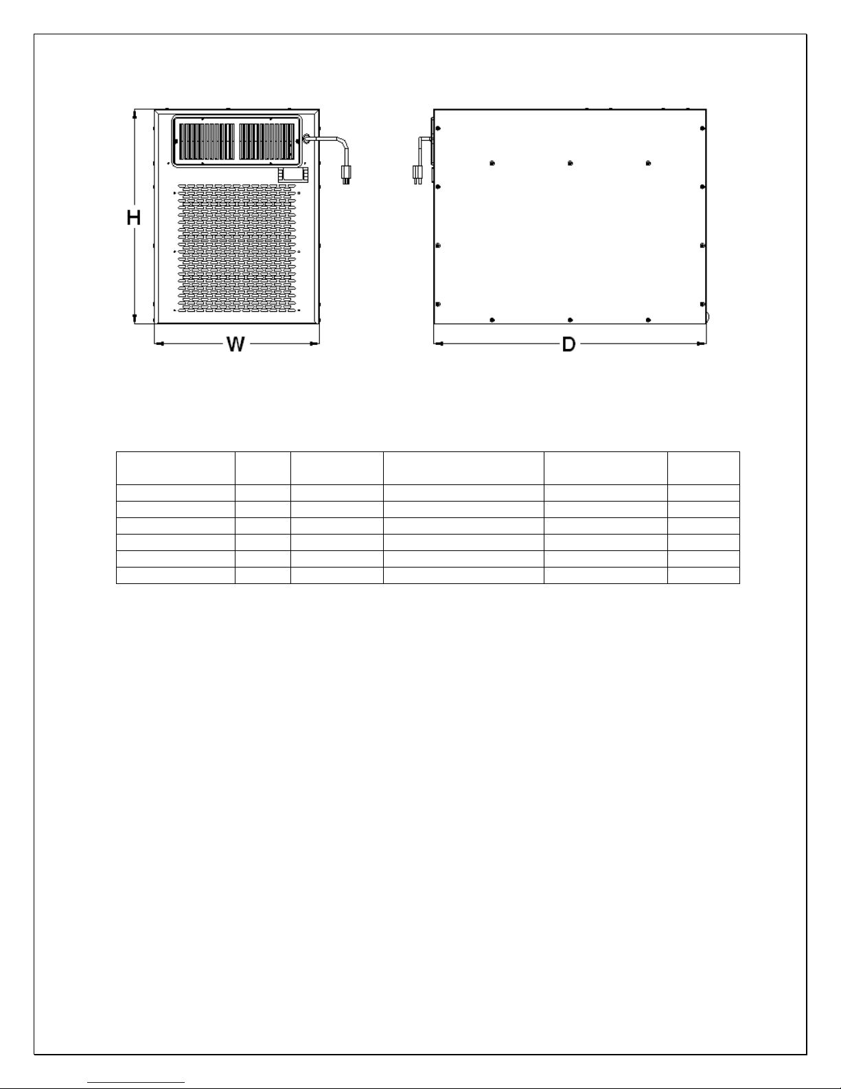
Fig. 1.4 WM-3520~8520HZD DIMENSIONS
The specifications and dimensions are listed as follows:
Model CFM
WM-1520HZD 100 90 14.25X16X13.25 220V/50HZ/2A 50
WM-2520HZD 150 180 14.25X16X13.25 220V/50HZ/3A 55
WM-3520HZD 200 600 14.25X21.25X19.75 220V/50Hz/3.5A 75
WM-4520HZD 200 900 14.25X21.25X19.75 220V/50Hz/4.5A 75
WM-6520HZD 420 1400 17X28X22 220V/50Hz/7A 110
WM-8520HZD 420 1800 17X28X22 220V/50Hz/8A 110
Cellar Size
(cu ft)
Dimensions
W”XD”XH”
Electrical
Weight
(lb)
NOTES:
• Also see the voltage, frequency and current specified on the label at the
cooling unit.
• The rated capacity is determined under the cellar and ambient
temperatures of 55°F and 75°F with R13 interior and R19 exterior
insulations. Any lower cellar temperature, higher ambient temperature
and less insulation will cause reducing capacity and may not maintain
°F.
55
• The ambient temperatures for WM-1520HZD shall not be higher than
78°F or lower than 50°F in order to operate properly.
• The ambient temperatures for WM-2520HZD shall not be higher than
95°F or lower than 50°F in order to operate properly.
• The ambient temperatures for WM-3520~8520HZD shall not be higher
than 95
°F or lower than 50°F in order to operate properly.
- 5 -
Installation Instructions
NOTES:
• Mounting brackets, screws, gaskets and other seal materials are not included.
• Do not install any ducts onto the supply, return, intake and exhaust.
• Because of potential safety hazards under a certain condition we strongly
recommend against the use of an extension cord. However, if you still select
to use an extension cord, it is absolutely necessary that it is a UL LISTED 3wire grounding type appliance extension cord having a 3-blade grounding
plug and a 3-slot receptacle that will plug into the appliance. The marked
rating of the extension cord shall be 220 V, 10 A or equivalent for WM1520~2520HZD, 220 V, 15 A or equivalent for WM-3520~8520HZD and not
greater than 15ft in length.
1. General Instructions
• The cooling unit produces cooling supplied into the cellar, meanwhile it also
generates heat that must be exhausted outside the cellar. So the cold- air
supply with return-air intake side and the hot-air exhaust with ambient-air
intake side must be separated and sealed. Through-wall installations can
separate these two sides.
• Furthermore, the condenser of cooling unit must intake adequate fresh
ambient-air to work properly. The ambient-air intake and hot-air exhaust must
not be short-circulated. Both of them must remain unobstructed 36” clearance
all around. The area into which the hot air is exhausted must be well
ventilated. If it is not, heat generated by the unit will build up and the unit will
not operate properly.
• Additionally, cold-air supply from the front grille must remain unobstructed 36”
clearance.
• The ambient temperatures shall not be above and below what are specified.
- 6 -
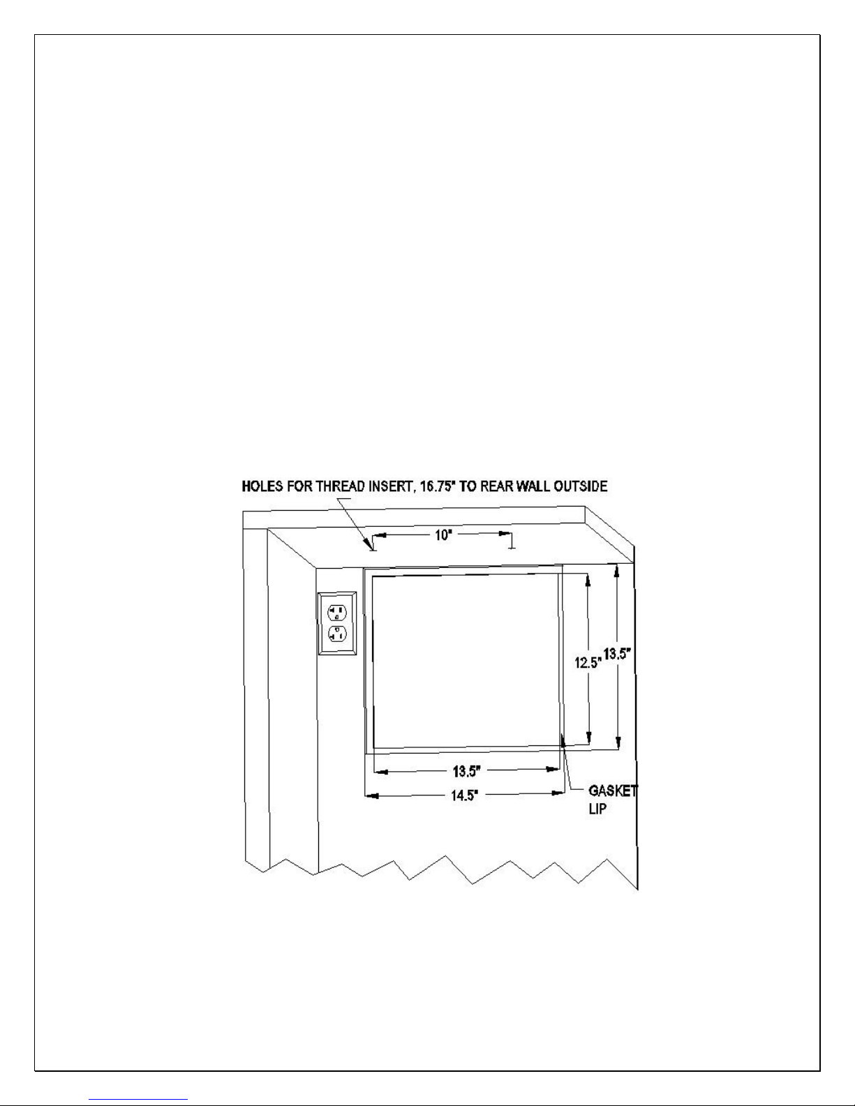
2. VINO1520~2520HZD cabinet installation
• Cut a rectangular inside opening with the 1/4” clearance inwards to the width
and height of the cooling unit. By not going through, leave 1/2” lip inside at the
wall to place the gaskets (see Fig 2.1).
• If top exhaust installation, cut another rectangular opening at the top of the
cabinet to the length and width of the top exhaust.
• Install 2 pieces of 1/4” ID wood thread inserts at the ceiling (see Fig.2.1 & 2.2).
• Place the gaskets (1/2” foam tape) on the mounting lip sides (see Fig 2.3).
• If top exhaust installation, place another gaskets along the top exhaust at the
top of the cooling unit (see Fig.2.4).
• Move the cooling unit towards the mounting sides and push to press the
gaskets (see Fig 2.5).
• Use 2 brackets and ¼” screws with 7/16” wrench to secure the cooling unit
(see Fig 2.6).
• Install the cabinet grille on the cabinet exterior wall (see Fig. 2.7).
• Plug the cooling unit in the cabinet receptacle.
• Plug the wine cabinet.
Fig. 2.1 CABINET CUTOUT & GASKET LIP
- 7 -
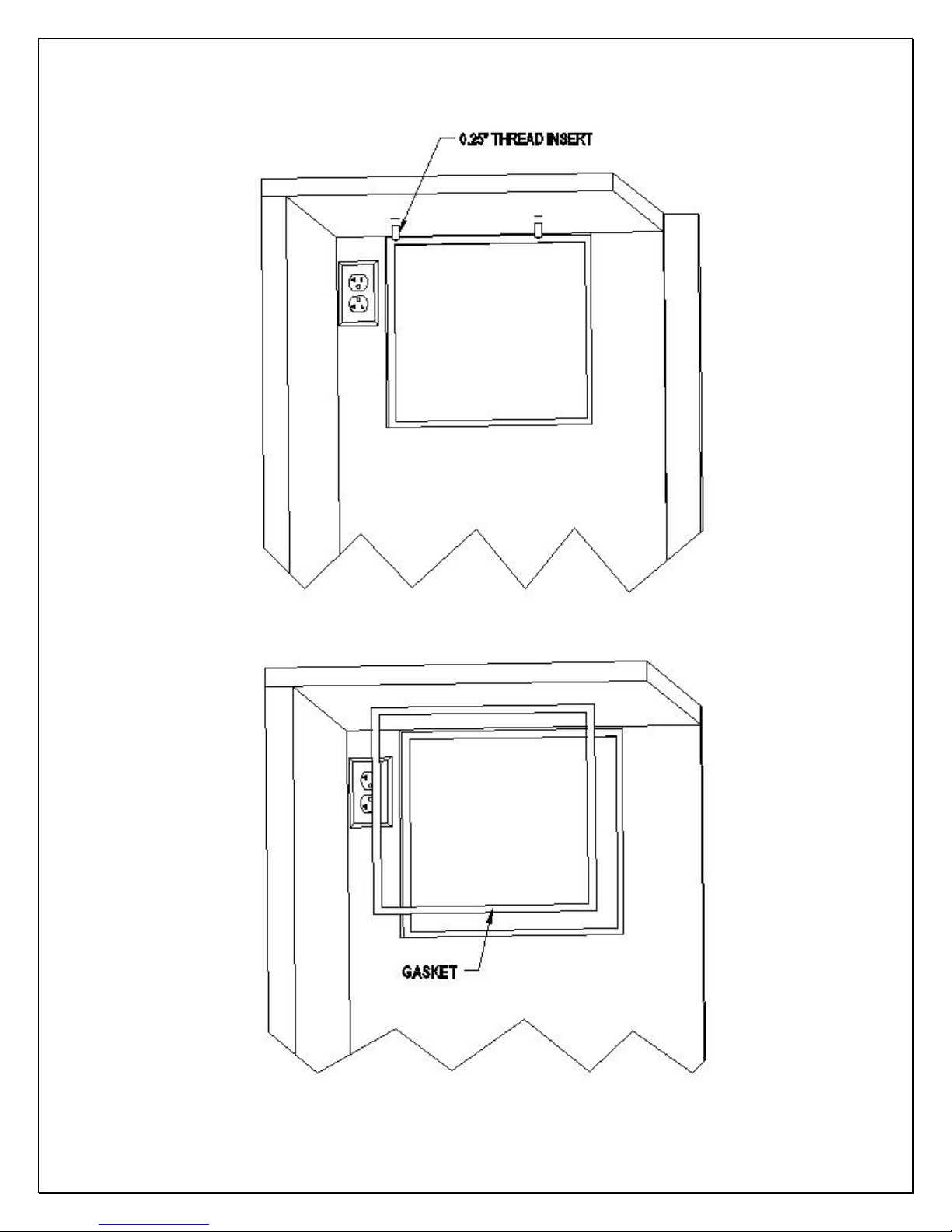
Fig. 2.2 THREAD INSERT
- 8 -
Fig. 2.3 REAR GASKET
 Loading...