

Vinotemp WINE-MATE WM-1520HTD, WM-1520HTD-TE, WM-2520HTD, WM-2520HTD-TE Installation, Use & Care Manual

wwwwww..wwiinneemmaattee..ccoomm
Wine Cooling System
WM-1520HTD WM-1520HTD-TE
WM-2520HTD WM-2520HTD-TE
Installation, Use & Care Manual
Read and save these instructions
wwwwww..vviinnootteemmpp..ccoomm
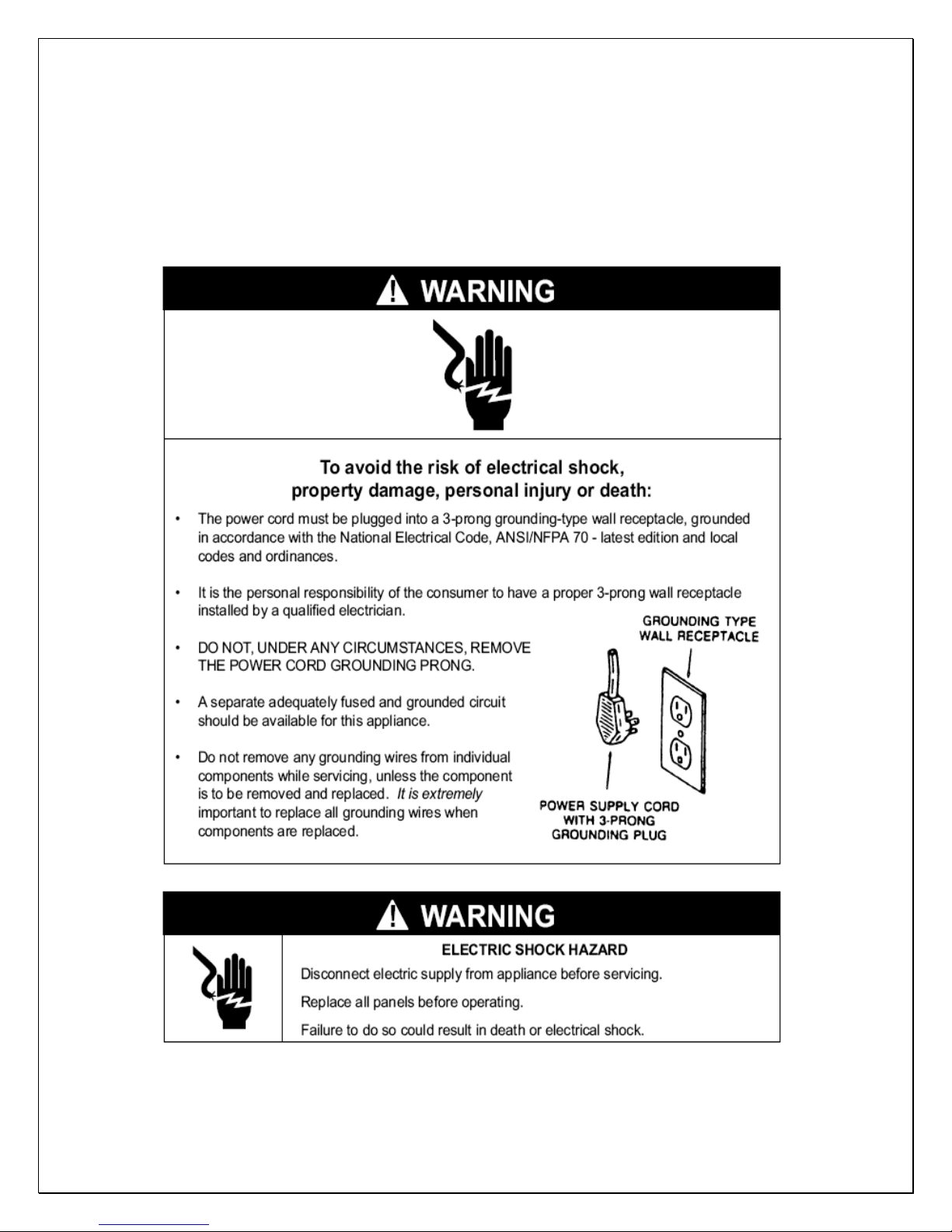
Important Safety Information
• DO NOT PLUG IN UNTIL 24 HOURS AFTER DELIVERY.
• DO NOT USE A GROUND FAULT INTERRUPTER (GFI).
• A DEDICATED 10 AMP CIRCUIT IS REQUIRED.
- 1 -
Table of Contents
Features & Specifications.…………………….……………..3
Installation Instructions..……………………………………..5
Temperature and Humidity……………..…………………..12
Care Guide…………………………………………..…………16
Troubleshooting……………………………………………..17
Wiring Diagram……………………………………….………20
Customer Support……………………………………………22
Warranty……………………………………………………….23
- 2 -

Features and Specifications
• WM-1520HTD, HTD-TE and WM-2520HTD, HTD-TE cooling units are
designed and used to provide a subtle temperature between 50~65 °F for a
properly insulated wine cabinet..
• The refrigerated space will maintain humidity range within 50~70% RH.
• These temperature and humidity ranges are optimized for long term storage
of wine.
• Temperature is controlled and humidity is adjusted using patented technology.
• Optimized air flow makes temperature even through the wine cabinet.
• Exchangeable supply grille can be used for front, back and down cold air
distribution.
• Multiple options for top and rear hot air exhaust are convenient for
installations.
• Extra insulations are used for both thermal and noise isolation
• Patented condensate drain tray is used for humidity adjustment
• The unit is self-contained ready for easy installation and use.
Fig. 1.1 FEATURE DESCRIPTION
- 3 -
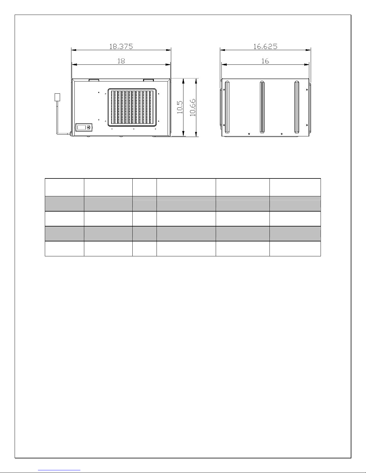
Fig. 1.2 DIMENSIONS (in)
The specifications and dimensions are listed as follows:
Model Exhaust CFM
WM-
1520htd
WM-
1520htd-te
WM-
2520htd
WM-
2520htd-te
Rear Exhaust
Top Exhaust 100 80 220V/50Hz/2A 55
Rear Exhaust 150 180 220V/50Hz/3A 60
Top Exhaust 150 180 220V/50Hz/3A 60
100 80 220V/50Hz/2A 55
Cabinet Size
(cu ft)
Electrical Weight (lb)
NOTES:
• Also see the voltage, frequency and current specified on the label at the
cooling unit.
• The rated capacity is determined under the cabinet and ambient
temperatures of 55
°F and 75°F with R13 interior and R19 exterior
insulations. Any lower cabinet temperature, higher ambient temperature
and less insulation will cause reducing capacity and may not maintain
55°F.
• The ambient temperatures for WM-1520HTD shall not be higher than
78
°F or lower than 50°F in order to operate properly.
• The ambient temperatures for WM-2520HTD shall not be higher than
95°F or lower than 50°F in order to operate properly.
- 4 -

Installation Instructions
NOTES:
• Mounting brackets, screws, gaskets and other seal materials are not included.
• Do not install any ducts onto the supply, return, intake and exhaust.
• Because of potential safety hazards under a certain condition, we strongly
recommend against the use of an extension cord. However, if you still elect to
use an extension cord, it is absolutely necessary that it will be a UL LISTED
3-wire grounding type appliance extension cord having a 3-blade grounding
plug and a 3-slot receptacle that will plug into the appliance. The marked
rating of the extension cord shall be 220 V, 10 A.
1. Cabinet Location
• Place the wine cabinet in a properly ventilated location. Otherwise, heat
exhausted by the cooling unit will build up and it will not operate properly.
• The exhaust area must not be closed space and must be ventilated. The
ambient temperatures shall not be higher than 78°F for a WM-1520HTD unit
and 95°F for a WM-2520HTD unit or lower than 50 °F.
1) Rear Exhaust Location
• Leave min 6 “clearance from the rear to the wall.
• Leave min 12” clearance from the top to the ceiling.
• Leave min 6” clearance from the left and right sides.
2) Front Exhaust Location
• Leave min 6” clearance from the front if left and right sides unobstructed.
• Or, leave min 36” clearance from the front if left and right sides obstructed
3) Top Exhaust Location
• Leave min 12” from the top to the ceiling.
• Leave min 2 “clearance from the rear to the wall.
• Leave min 2” clearance from the left and right sides.
4) Side Exhaust Location
• Leave min 6 “clearance from the left or right side to the wall.
• Leave min 12” clearance from the top to the ceiling.
2. Cooling Unit Installation
• The cooling unit produces cooling supplied into the cabinet, meanwhile it also
generates heat that must be exhausted outside the cabinet. So the cold-air
supply with return-air intake and hot-air exhaust with ambient-air side must be
separated and sealed. Foam tape gasket may be used to seal them. The
cooling unit must intake adequate fresh ambient-air to work properly. The
- 5 -

ambient-air intake and hot-air exhaust must not be short-circulated. A piece of
wood may be used to separate them.
• Cut a rectangular inside opening at the rear of the cabinet with the 1/4”
clearance inwards to the width and height of the cooling unit. By not going
through, leave 1/2” lip inside at the wall to place the gaskets (see Fig. 2.1 &
2.2).
• If top exhaust installation, cut another rectangular opening at the top of the
cabinet to the length and width of the top exhaust (see Fig.2.1 & 2.3).
• Install 2 pieces of ¼” ID wood thread inserts at the ceiling (see Fig.2.1 & 2.4).
• Place the gaskets (½ “foam tape) on the gasket lips (see Fig 2.1 & 2.5).
• If top exhaust installation, place another gaskets along the top exhaust at the
top of the cooling unit (see Fig.2.6).
• Move the cooling unit towards the mounting sides and push to press the
gaskets.
• Use 2 mounting brackets and ¼” screws with 7/16” wrench to secure the
cooling unit (see Fig 2.7 & 2.8).
• If top exhaust, install another top exhaust grille at the top of the cabinet (see
Fig 2.9).
• Plug the cooling unit in the cabinet receptacle.
• Plug the wine cabinet.
- 6 -

Fig. 2.1 CUTOUT AND HOLE DIMENSIONS
Fig. 2.2 REAR EXHAUST CUTOUT
- 7 -
 Loading...