

Vinotemp WINE-MATE WM1500 HTD-TE, WINE-MATE WM2500 HTD, WINE-MATE WM2500 HTD-TE, WINE-MATE WM1500 HTD Use And Care Manual
WINE-MATE Cooling Unit
Use & Care Manual
WM1500 HTD, HTD-TE
WM2500 HTD, HTD-TE
VViinnootteemmpp IInntteerrnnaattiioonnaall CCoorrpp..
wwwwww..vviinnootteemmpp..ccoom
wwwwww..wwiinneemmaattee..ccoom
m
m

Important Safety Information
• DO NOT PLUG IN UNTIL 24 HOURS AFTER DELIVERY.
• DO NOT USE A GROUND FAULT INTERRUPTER (GFI).
• A DEDICATED 20 AMP CIRCUIT IS REQUIRED.
- 1 -
TABLE OF CONTENTS
Features & Specifications.…………………….……………..3
Installation Instruction………………………………………..5
Temperature Control & Humidity Adjustment……..……11
Care Guide……………………………………………………14
Troubleshooting……………………………………………..16
Wiring Diagram……………………………………….………19
Customer Support……………………………………………20
Warranty……………………………………………………….21
- 2 -
Features and Specifications
• WM1500HTD, HTD-TE and WM2500HTD, HTD-TE cooling units are
designed and used to provide a subtle temperature between 50~65 °F for
suitable space at a normal environment.
• The refrigerated space will maintain humidity of 50~70% RH even when
the environment becomes dry and humid.
• These temperatures and humilities ar e optimized for long term storage of
wine.
• Humidity and temperature digital control using patent pending technology
• Optimized air flow for most even temperatures in wine cabinets
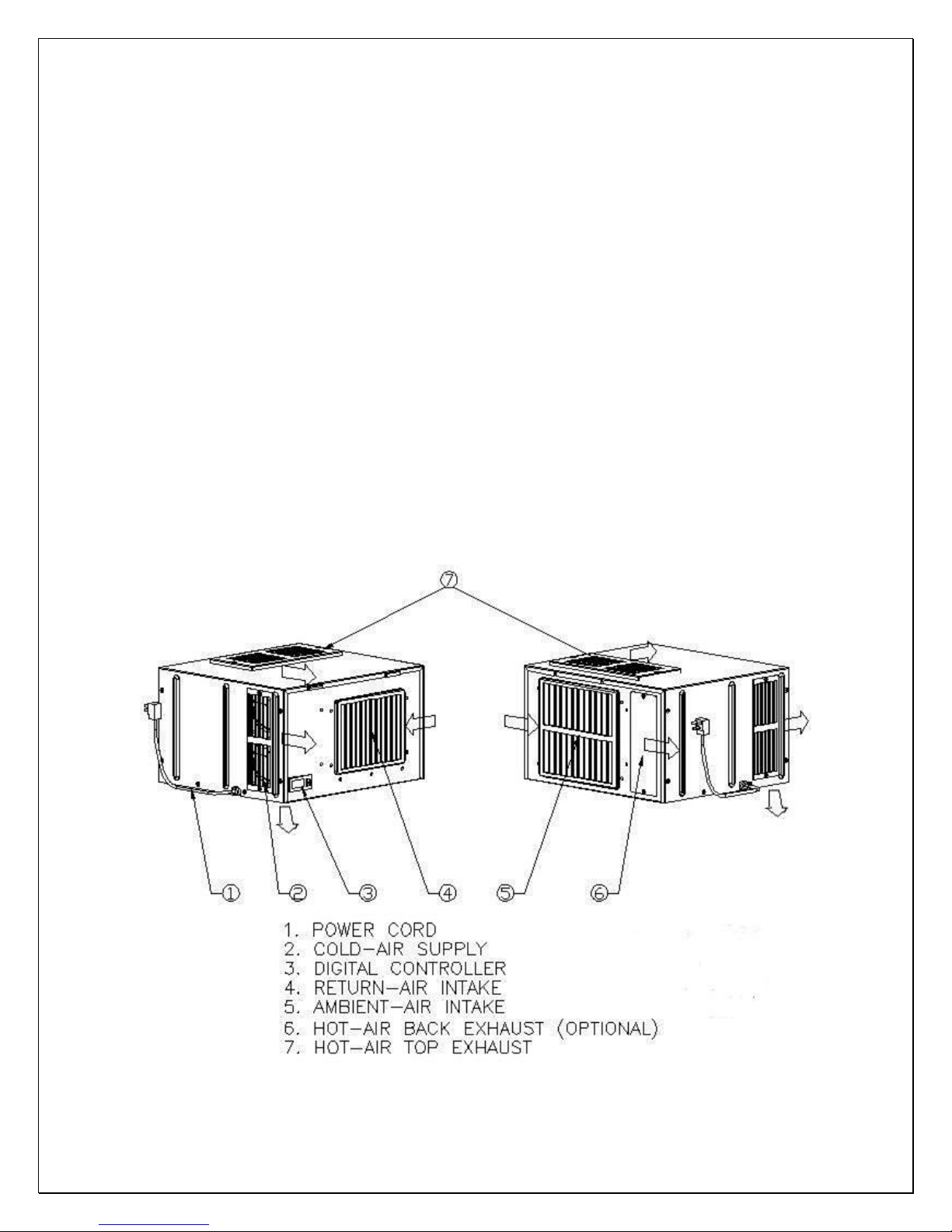
• Exchangeable supply grille for front, back and down cold air distribution
• Multiple options for top and rear hot air exhaust
• High efficient tube-axial fans for both condenser and evaporator
• Extra insulation for both thermal and noise isolation
• Unique condensate drain tray for humidity adjustment
• Grill size optimized for easy cleaning and safety
• Stamping ribbed housing for robust structure
• Self-contained ready for use and easy for installation
Fig. 1.1 FEATURE DESCRIPTION
- 3 -
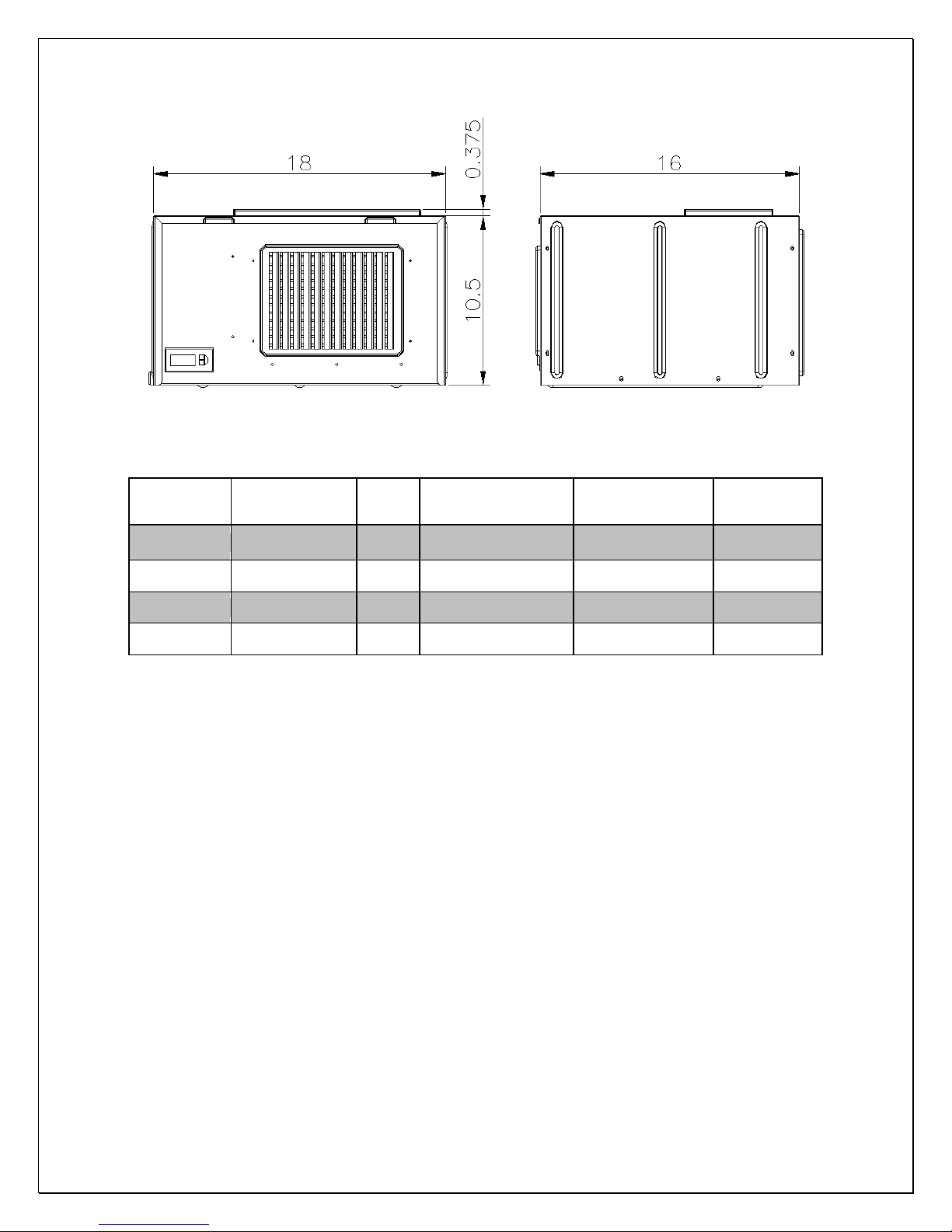
Fig. 1.2 DIMENSIONS (in)
The dimensions and capacity are specified as follows:
Model Exhaust CFM
Capacity cu ft
(55°F/75°F)
Electrical
Weight
(lb)
1500htd
1500htd-te Top Exhaust 120 90 115V/60Hz/4A 55
2500htd Rear Exhaust 180 200 115V/60Hz/5A 60
2500htd-te Top Exhaust 180 200 115V/60Hz/5A 60
Rear Exhaust
120 90 115V/60Hz/4A 55
NOTES:
• See the voltage, frequency and current specified on the label at the
cooling unit.
• Capacity is determined under the cabinet and ambient temperatures of
°F and 75°F with R11 interior and R19 exterior insulations. Any lower
55
cabinet and higher ambient temperatures will reduce the capacity.
- 4 -

Installation Instruction
NOTES:
1) DO NOT INSTALL ANY DUCTS ONTO THE SUPPLY, INTAKE AND
EXHAUST.
2) MOUNTING BRACKETS, SCREWS, GASKETS AND OTHER SEAL
MATERIALS ARE NOT INCLUDED.
1. Cabinet Location
• Place the wine cabinet in a properly ventilated location. Otherwise, heat
exhausted by the cooling unit will build up and it will not operate properly.
• The exhaust area must not be closed spac e and must be ventilated. The
ambient temperatures shall not be higher than 78°F for a WM-1500HTD
unit and 95°F for a WM-2500HTD unit or lower than 50 °F.
1) Rear Exhaust Location
• Leave min 6 “clearance from the rear to the wall.
• Leave min 12” clearance from the top to the ceiling.
• Leave min 6” clearance from the left and right sides.
2) Front Exhaust Location
• Leave min 6” clearance from the front if left and right sides unobstructed.
• Or, leave min 36” clearance from the front if left and right sides obstructed
3) Top Exhaust Location
• Leave min 12” from the top to the ceiling.
• Leave min 2 “clearance from the rear to the wall.
• Leave min 2” clearance from the left and right sides.
4) Side Exhaust Location
• Leave min 6 “clearance from the left or right side to the wall.
• Leave min 12” clearance from the top to the ceiling.
2. Cooling Unit Installation
• The cooling unit produces cooling supplied into the cabinet, and it also
generates heat that must be exhausted outside the cabinet. So the cold
supply side and hot exhaust side must be separated and sealed (see Fig.
2.5 & 2.6). Foam tape may be used to seal them. The cooling unit must
intake adequate fresh ambient-air to work properly. The ambient-air intake
and warm-air exhaust must not be short-circulated. A piece of wood may
be used to separate them.
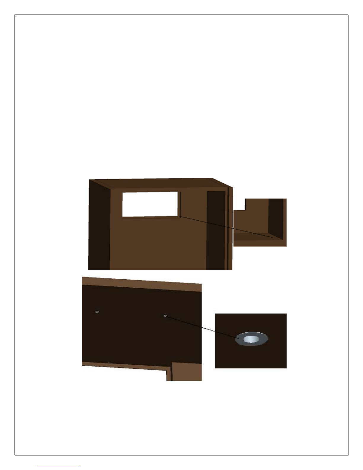
• Cut a rectangular inside opening at the rear of the cabinet with the 1/4”
clearance inwards to the width and height of the cooling unit. By not going
through, leave 1/2” lip inside at the wall to place the gaskets (see Fig. 2.1
& 2.3).
- 5 -
• If top exhaust, cut another rectangular opening at the top of the cabinet to
the length and width of the top exhaust (see Fig.2.2 & 2.3).
• Make 2 holes at the ceiling and install the ¼” inside diameter wood thread
inserts (see Fig.2.1 & 2.3).
• Place the gaskets (1/2” foam tape) on the gasket lips (see Fig 2.4).
• If top exhaust, place another gaskets along the top exhaust at the top of
the cooling unit (see Fig.2.9).
• Move the cooling unit towards the mounting sides and push to press the
gaskets.
• Fasten the 2 brackets and use 7/16” wrench to tighten the two ¼” screws
(see Fig 2.5, 2.6 & 2.7).
• If top exhaust, install another top exhaust grille at the top of the cabinet
(see Fig 2.8).
• Plug the cooling unit in receptacle.
• Plug the wine cabinet.
Fig. 2.1 MOUNTING CUTOUT AND SCREW INSERT
- 6 -
 Loading...