

Vinotemp Wine-Mate WM-1500CD, Wine-Mate WM-1500CTED, Wine-Mate WM-2500CD, Wine-Mate WM-2500CTED, WINE-MATE WM-2520CTED Installation, Use & Care Manual
wwwwww..wwiinneemmaattee..ccoomm
Wine Cooling System
WM-1500CD WM-1500CTED
WM-2500CD WM-2500CTED
Installation, Use & Care Manual
Read and save these instructions
wwwwww..vviinnootteemmpp..ccoomm
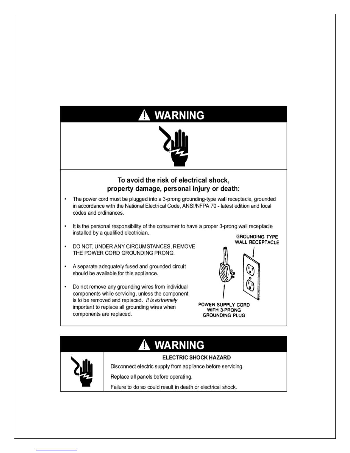
Important Safety Information
• DO NOT PLUG IN UNTIL 24 HOURS AFTER DELIVERY.
• DO NOT USE A GROUND FAULT INTERRUPTER (GFI).
• A DEDICATED 20 AMP CIRCUIT IS REQUIRED.
- 1 -

Table of Contents
Features & Specifications…………….………….…………..3
Installation Instructions……………………………………..5
Temperature and Humidity ……………………………..…10
Care Guide………………………………..…………………14
Troubleshooting……………………………………………..15
Wiring Diagram……………………………………….………18
Customer Support……………………………………………20
Warranty……………………………………………………….21
- 2 -
Features and Specifications
• WM-1500CD, CTED and WM-2500CD, CTED cooling units are designed and
used to provide a subtle temperature between 50~65 °F for a properly
insulated wine cabinet.
• The refrigerated space will maintain humidity range within 50~70% RH.
• These temperature and humidity ranges are optimized for long term storage
of wine.
• Temperature is controlled and humidity is adjusted using patented technology.
• Bottom cold-air supply is optimized for use in the wine cabinets.
• Multiple options for top and rear hot air exhaust are convenient for
installations.
• The unit is self-contained ready for easy installation and use.
- 3 -
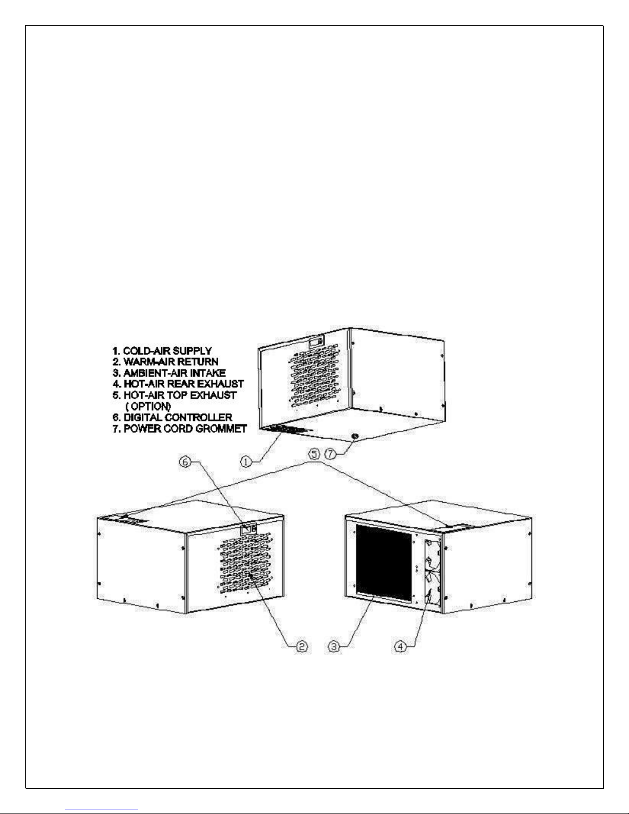
Fig. 1.1 FEATURE DESCRIPTIONS

Fig. 1.2 DIMENSIONS (in)
The specifications and dimensions are listed as follows:
Model Exhaust CFM
Cabinet Size
(cu ft)
Electrical Weight(lb)
WM-1500cd
WM-
1500cted
WM-2500cd Rear Exhaust 180 200 115V/60Hz/5A 55
WM-
2500cted
Rear Exhaust
Top Exhaust 120 90 115V/60Hz/4A 50
Top Exhaust 180 200 115V/60Hz/5A 55
120 90 115V/60Hz/4A 50
NOTES:
• Also see the voltage, frequency and current specified on the label at the
cooling unit.
• The rated capacity is determined under the cabinet and ambient
temperatures of 55°F and 75°F with R13 interior and R19 exterior
insulations. Any lower cabinet temperature, higher ambient temperature
and less insulation will cause reducing capacity and may not maintain
°F.
55
• The ambient temperatures for WM-1500CD shall not be higher than 78°F
or lower than 50°F in order to operate properly.
• The ambient temperatures for WM-2500CD shall not be higher than 95°F
or lower than 50
°F in order to operate properly.
- 4 -
Installation Instructions
NOTES:
• Mounting brackets, screws, gaskets and other seal materials are not included.
• Do not install any ducts onto the supply, return, intake and exhaust.
• There is a grommet on the power cord. Press and fit the grommet into the
hole at the bottom of the cooling unit to prevent the exhaust air from going to
the cabinet.
• We strongly recommend against the use of an extension cord. However, if
you still select to use an extension cord, it is absolutely necessary that it is a
UL LISTED 3-wire grounding type appliance extension cord. The marked
rating of the extension cord shall be 115 V, 15 A. or equivalent and not
greater than 15ft in length.
1. Cabinet Location
• Place the wine cabinet in a properly ventilated location. Otherwise, heat
exhausted by the cooling unit will build up and it will not operate properly.
• The exhaust area must not be a closed space and must be ventilated.
• The ambient temperatures shall not be higher than 78°F for a WM-1500CD
unit and 95°F for a WM-2500CD unit or lower than 50 °F.
1) Rear Exhaust Location
• Leave min 6 “clearance from the rear to the wall.
• Leave min 12” clearance from the top to the ceiling.
• Leave min 6” clearance from the left and right sides.
2) Front Exhaust Location
• Leave min 6” clearance from the front if left and right sides unobstructed.
• Or, leave min 36” clearance from the front if left and right sides obstructed
3) Top Exhaust Location
• Leave min 12” from the top to the ceiling.
• Leave min 2 “clearance from the rear to the wall.
• Leave min 2” clearance from the left and right sides.
4) Side Exhaust Location
• Leave min 6 “clearance from the left or right side to the wall.
• Leave min 12” clearance from the top to the ceiling.
2. Cooling Unit Installation
- 5 -
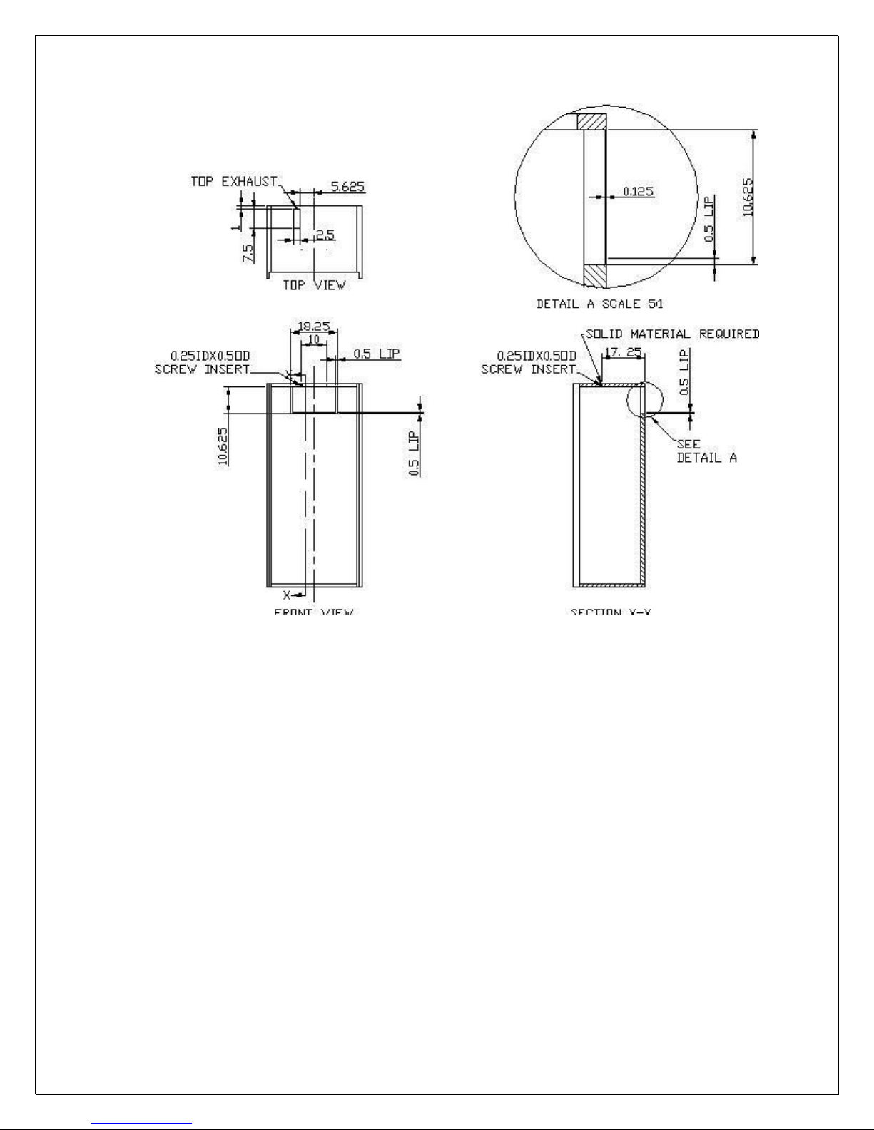
Fig. 2.1 CUTOUT AND HOLE DIMENSIONS
• The cooling unit produces cooling supplied into the cabinet, meanwhile it also
generates heat that must be exhausted outside the cabinet. So the cold-air
supply with return-air intake and hot-air exhaust with ambient-air side must be
separated and sealed. Foam tape gasket may be used to seal them. The
cooling unit must intake adequate fresh ambient-air to work properly. The
ambient-air intake and hot-air exhaust must not be short-circulated. A piece of
wood may be used to separate them.
• Cut a rectangular inside opening at the rear of the cabinet with the 1/4”
clearance inwards to the width and height of the cooling unit. By not going
through, leave 1/2” lip inside at the wall to place the gaskets (see Fig. 2.1 &
2.2).
• If top exhaust installation, cut another rectangular opening at the top of the
cabinet to the length and width of the top exhaust (see Fig.2.1 & 2.3).
• Install 2 pieces of 1/4” ID wood thread inserts at the ceiling (see Fig.2.1 & 2.4).
• Place the gaskets (1/2” foam tape) on the gasket lips (see Fig 2.5).
• If top exhaust, place another gaskets along the top exhaust at the top of the
cooling unit (see Fig.2.6).
- 6 -
 Loading...