

Vinotemp WINE-MATE VINO2500SSD, WINE-MATE VINO4500SSD, WINE-MATE VINO6500SSD, WINE-MATE VINO8500SSD Installation & Operation Manual
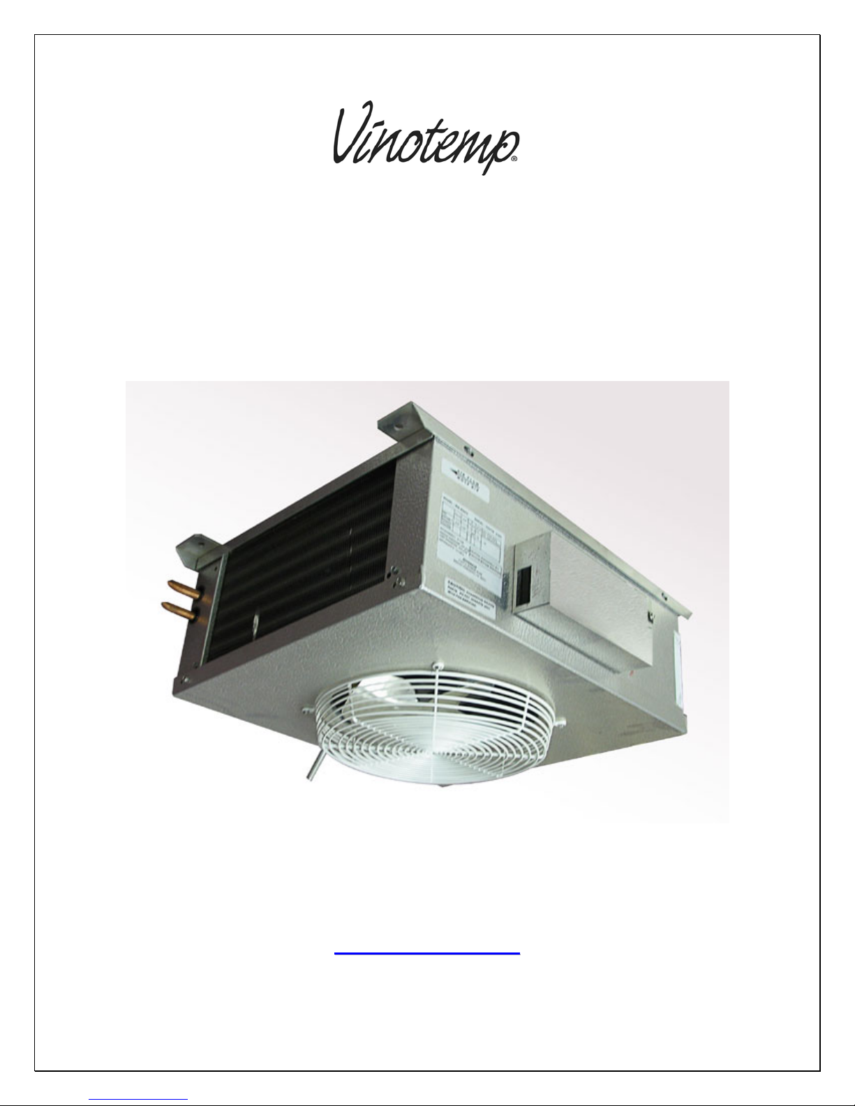
WINE-MATE Split System
Installation, Operation & Care Manual
VINO2500SSD, 4500SSD
VINO6500SSD, 8500SSD
VViinnootteemmpp IInntteerrnnaattiioonnaall CCoorrpp..
READ AND SAVE THESE INSTRUCTIONS
wwwwww..wwiinneemmaattee..ccoom
m
TABLE OF CONTENTS
Important Safety Information….........................................2
Feature Description…………………………….……………..3
Installer’s Instruction…………….…..….……..……………..6
Temperature Control & Humidity Adjustment.………….13
Care Guide…………………………………………………….18
User’ Troubleshooting…….………………………………...19
Customer Support……………………………………………22
Warranty……………………………………………………….23
- 1 -
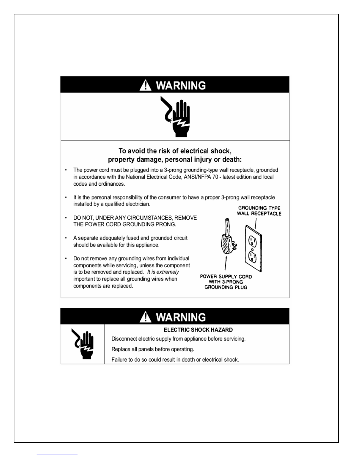
Important Safety Information
• DO NOT USE A GROUND FAULT INTERRUPTER (GFI).
• A DEDICATED 20 AMP CIRCUIT IS HIGHLY RECOMMENDED.
- 2 -
MODEL
VINO-
2500SSD
VINO-
4500SSD
VINO-
6500SSD
VINO-
8500SSD
Feature Description
• Wine-Mate split cooling system is designed and used to provide a cold
temperature between 50~65
normal environment.
• The wine room will maintain humidity of 50~70% RH even when the
environment becomes dry and humid.
• These temperatures and humilities are optimized for long term storage of
wine.
• The condensing unit can be located away from the wine cellar or other
refrigerated enclosure as far as 50 feet, which will bring you quiet
operation.
• The SSD units provide two way air supply operation. The evaporator units
can be installed on the ceiling in a cabinet or room.
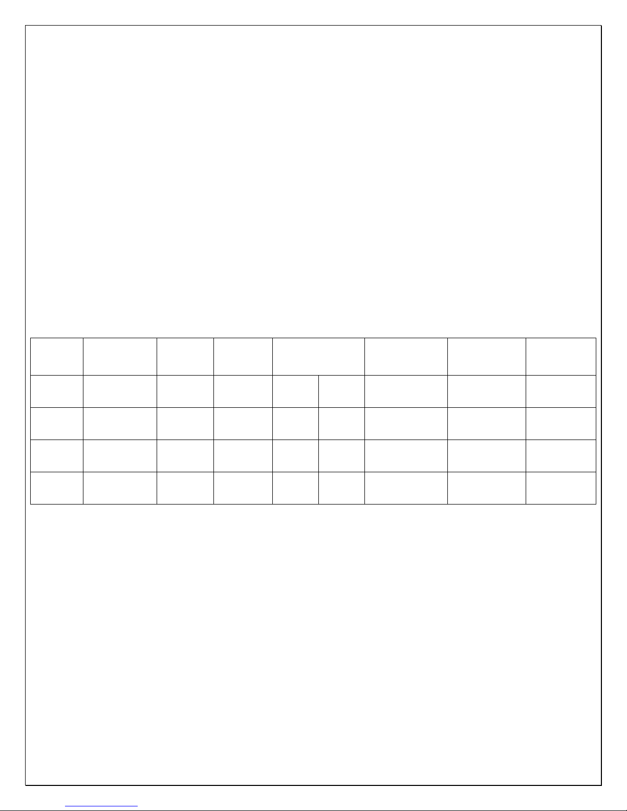
The dimensions and capacities are specified as follows:
EVAP UNIT
W”xH”xD”
WM-25SFCD
17.5X7.5X23
WM-45SFCD
17.5X10.5X23
WM-65SFCD
21X11.75X30
WM-85SFCD
21X13.5X30
COND
UNIT
L”xH”xD”
WM-
25SCU
18x14x12
WM-
45SCU
18x14x12
WM-
65SCU
24x17x18
WM-
85SCU
24x17x18
Btu/h
°F)
(55/90
CFM
2500/350
4500/460
6500/660
8500/810
°F for a properly insulated wine room at a
BOTTLE
CAPACITY
(55/75
250
cu ft
1000
cu ft
1500
cu ft
2000
cu ft
°F)
1200
bottles
4500
bottles
6500
bottles
8500
bottles
REFRIGERANT
R134a
R134a
R134a
R134a
ELECTRICAL
EVAP UNIT/
COND UNIT
115V-60HZ-1A /
115V-60HZ-
5.7A
115V-60HZ-1A /
115V-60HZ-
6.9A
115V-60HZ-
1.5A / 115V60HZ-12A
115V-60HZ-
1.5A / 115V60HZ-15A
WEIGHT(lb)
EVAP UNIT/
COND UNIT
35/40
40/60
66/90
95/115
- 3 -
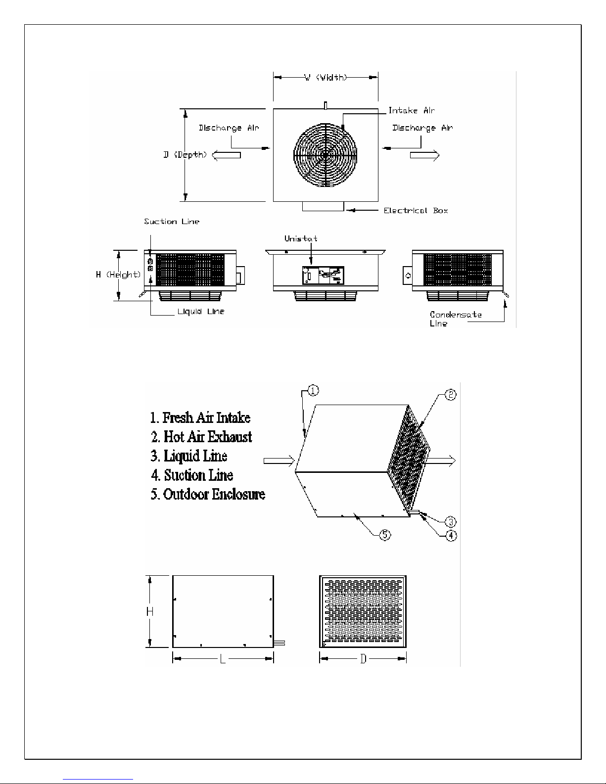
Fig. 1.1 WM25-85SFCD Evaporator Unit
Fig. 1.2 WM25-45SCU Condensing Unit
- 4 -

Fig. 1.3 WM65-85SCU Condensing Unit
- 5 -
Installer’s Instruction
Federal law requires that WINE-MATE split cooling systems be
installed by an EPA certified refrigeration technician.
WINE-MATE split system is shipped as components and is ready for use only
after a certified refrigeration technician has properly installed and tested the
system. Proper installation is critical. Vinotemp can only warrant the quality of the
components. The installation and proper operation of the system must be
warranted by the installer. Installation of the system must be done in accordance
with all state and local building codes.
The condensing unit and evaporator unit are connected by a liquid line and an
insulated suction line that are supplied by the installer. These lines must be
properly sized for the distance between the two units. After the units and the lines
are installed, the system must be pressure tested. If no leaks are found,
evacuate and charge system with R134A. Refrigerant amount will vary
depending on the length of line set.
1. Condensing Unit
• Place the condensing unit in a properly ventilated location. If it is not, heat
exhausted by the condensing unit will build up and the cooling system will
not operate properly.
• Leave minimum 5 feet clearance for the exhaust side and leave minimum
1 foot clearance for the fresh air intake side.
• Condensing unit should be elevated to avoid possible flooding and shaded
from direct sun. It should not be exposed to temperatures higher than 110
°F or lower than 45 °F (optional low ambient kit for 20 °F).
2. Evaporator Unit
• The WM25-85SFCD evaporator units should be installed for ceiling mount
with air supply on both sides and air return on the bottom.
- 6 -
• Supply and return air flow from the evaporator unit should be unobstructed
for at least 1 foot.
3. Air Sensor
• The air sensor can be located in the wine room or the return air area, but
not the supply air area.
4. Refrigeration Piping and Charging
• If equipped with a TXV, the evaporator superheat is set around 8 °F for a
10 °F TD system at factory.
• If equipped with an AXV, the valve is set around 38-40°F at factory.
• The charge may be complete when there are no more bubbles forming in
the sight glass. The subcooling at the condensing unit is around 10°F and
the superheat at the evaporator unit is around 8°F at 75°F ambient
temperature.
• The installation order starts from condensing unit (including the receiver),
liquid line filter-drier, moisture-liquid indicator (sight glass), liquid line,
evaporator unit (including liquid line solenoid valve and thermostatic
expansion valve or automatic expansion valve), suction line, and returning
to condensing unit.
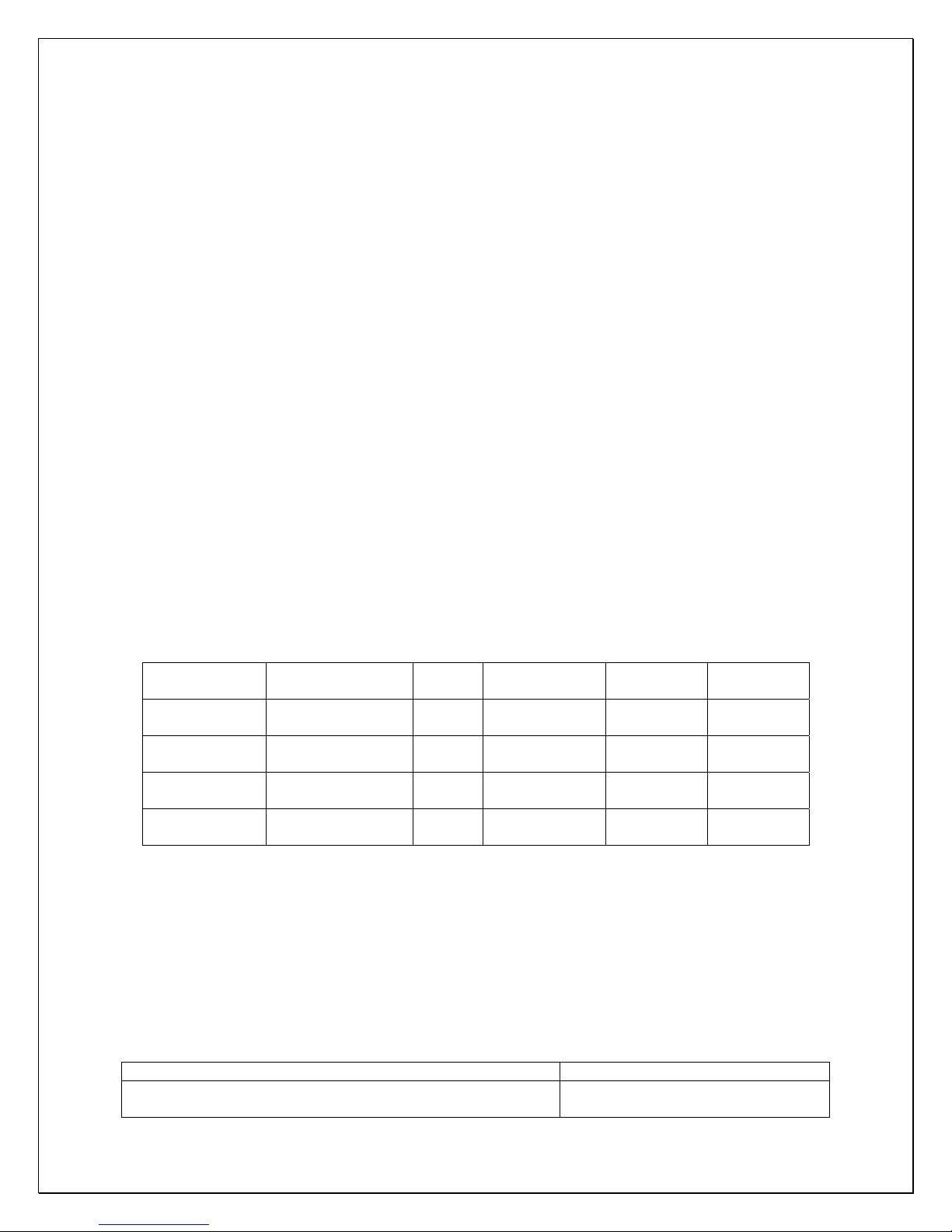
The line sizes and refrigerant charges are listed as follows.
MODEL
VINO-
2500SSD
VINO-
4500SSD
VINO-
6500SSD
VINO-
8500SSD
REFRIGERATION
LINES
< 50 FT
< 50 FT
< 50 FT
< 50 FT
LIQUID
LINE
1/4"
OD
1/4"
OD
1/4"
OD
3/8"
OD
SUCTION
LINE
3/8” OD 1/2” OD
1/2” OD 1/2” OD
5/8” OD 1/2” OD
5/8” OD 1/2” OD
DRAIN
LINE
CHARGE
R134a/
20 OZ
R134a/
26 OZ
R134a/
32 OZ
R134a/
38 OZ
5. Pressure, Superheat and Subcooling Readings
NOTES: THE VALVES MUST BE IN THE MIDDLE POSITIONS TO READ
PROPERLY.
Low side pressure: 33 psig.
High side pressure: 130 psig at 75
°F ambient temperature and 150 psig at 90 °F
ambient temperature.
Complaint Possible Causes
a. High suction pressure and low head pressure
b. High suction pressure and low head pressure
a. Compressor may be bad
b. Expansion valve opened, too
- 7 -
 Loading...