

Vinotemp WINE-MATE VINO4500DS, WINE-MATE VINO8500DS, WINE-MATE VINO6500DS Installation & Operation Manual
wwwwww..wwiinneemmaattee..ccoomm
WINE-MATE Ducted System
Installation, Operation & Care Manual
VINO4500DS VINO6500DS VINO8500DS
VViinnootteemmpp IInntteerrnnaattiioonnaall CCoorrpp..
READ AND SAVE THESE INSTRUCTIONS
wwwwww..vviinnootteemmpp..ccoomm
TABLE OF CONTENTS
Important Safety Information…..........................................2
Features & Specifications.…………………….……………..3
Cellar Construction.…………………………….……………..5
Installer’s Instruction…………….…..….……..……………..6
Temperature Control & Humidity Adjustment....…………9
Service Guide………………….……………………………...12
Electrical Wiring…………….……………………………...18
Care Guide…………………………………………………….24
User’ Troubleshooting…….………………………………...25
Customer Support……………………………………………28
Warranty……………………………………………………….29
- 1 -
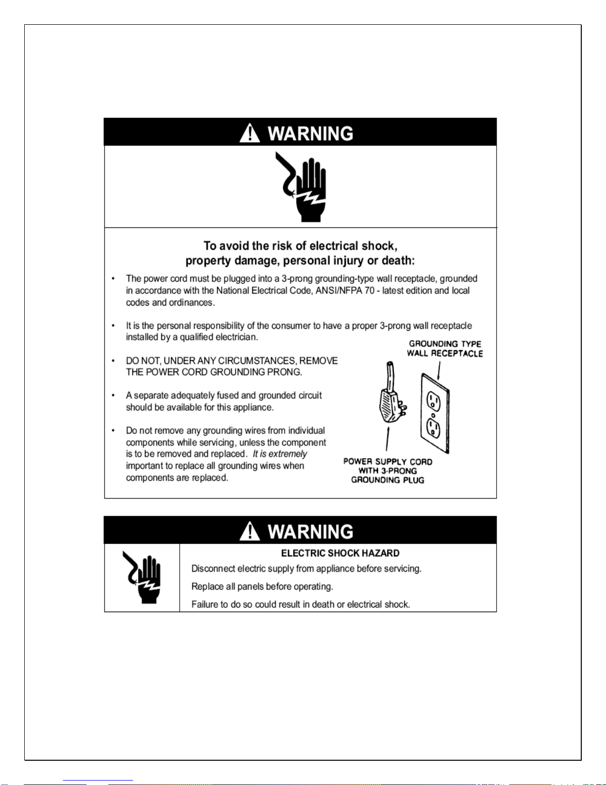
Important Safety Information
WARNING:
• DO NOT USE A GROUND FAULT INTERRUPTER (GFI).
• A DEDICATED 20 OR 30 AMP CIRCUIT IS REQUIRED (4500DS OR 6500-
8500DS).
- 2 -
Features and Specifications
• WINE-MATE ducted system VINO4500-8500DS are designed and used to
provide a cold temperature between 50~65
wine room at a normal environment.
• The wine room will maintain humidity of 50~70% RH even when the
environment becomes dry and humid. These temperatures and humilities
are optimized for long term storage of wine.
• The DS ducted systems are designed for both outdoor and indoor
installation.
• Back-curved impeller fans are good for total 50 ft long duct to cut the
operation noise.
• Self-contained ready for use with no extra refrigeration tubing in the field.
°F for a properly insulated
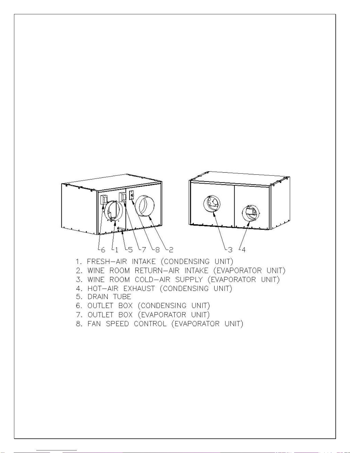
Fig. 1 VINO4500-8500DS FEATURES
- 3 -
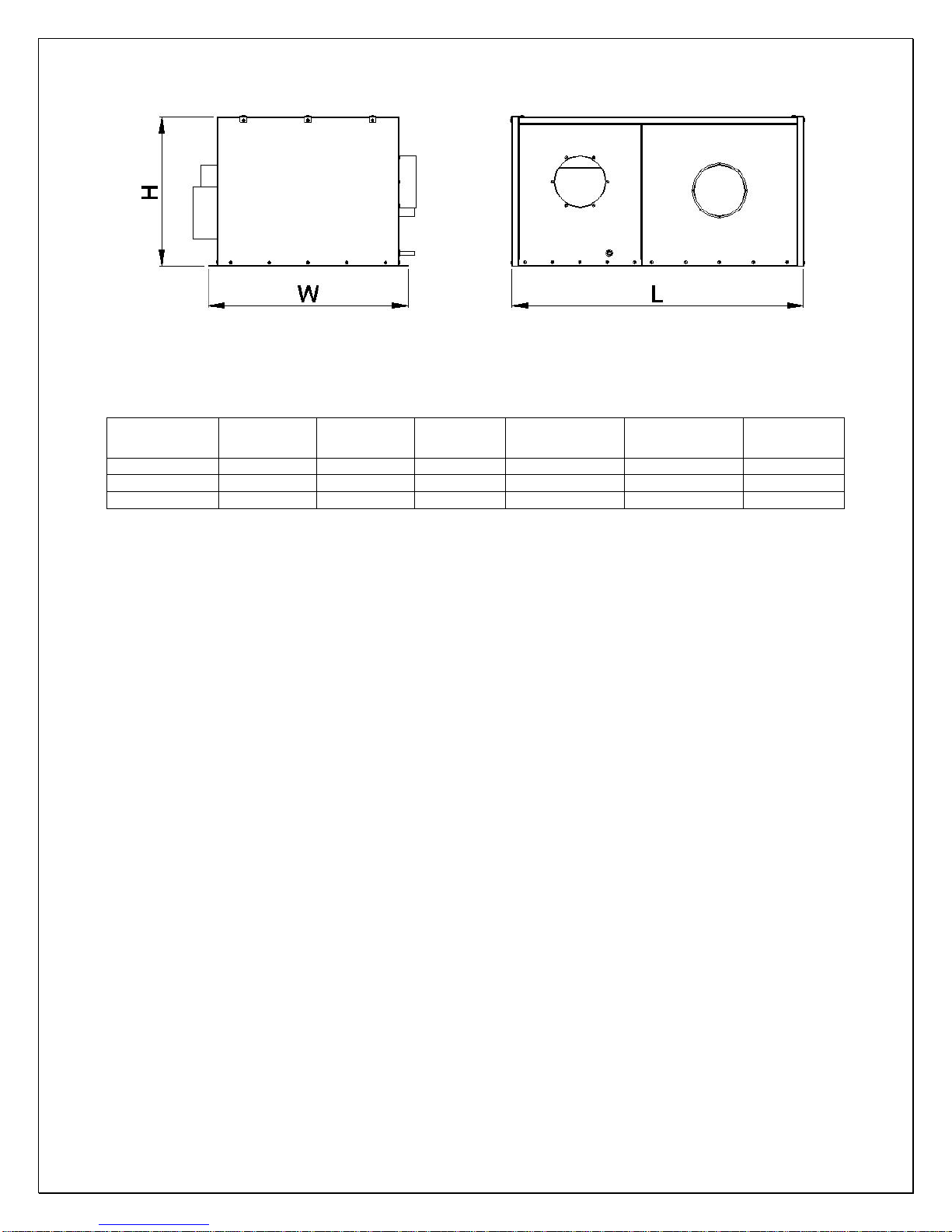
Fig. 2 VINO4500- 8500DS DIMENSIONS
The dimensions and capacities are specified as follows:
MODEL
VINO-4500DS 45X34X23 4500/380 1000 cu ft R134a 115V-60HZ-8A 140
VINO-6500DS 45X34X23 6500/490 1500 cu ft R134a 115V-60HZ-14A 170
VINO-8500DS 45X34X25 8500/750 2000 cu ft R134a 115V-60HZ-17A 220
DIMENSION
L”xW”xH”
Btu/h, CFM
(55/90
°F)
CAPACITY
(55/75°F)
REFRIGERANT ELECTRICAL WEIGHT(lb)
NOTE:
CAPACITY IS DETERMINED UNDER THE CELLAR AND AMBIENT
TEMPERATURES OF 55°F AND 75°F WITH R11 INTERIOR AND R19
EXTERIOR INSULATIONS. ANY LOWER CABINET AND HIGHER AMBIENT
TEMPERATURES WILL REDUCE THE CAPACITY.
CAUTION:
LOW AMBIENT TEMPERATURE KIT IS REQUIRED IF THE INSTALLATION
AREA WILL BE BELOW 50°F.
CAUTION:
LIQUID AND SUCTION LINES MAY DIFFER FROM WHAT ARE SHOWN
HERE, PLEASE CHECK ON THE UNITS FOR PROPER INSTALLATION.
Parts included:
Self-contained Cooling Unit
Temperature Controller (4.5”LX4.5”WX3.75”D) + Air Sensor
- 4 -
Cellar Construction
This is only a guide and shall be considered as minimum requirements.
All interior walls and floors shall have a vapor barrier and a minimum of R11
insulation. All exterior walls and ceiling shall have a vapor barrier and a minimum
of R19 insulation. The vapor barrier shall be installed on the warm side of the
insulation. All joints, door frames, electrical outlets or switches and any pipes or
vents that go through the enclosure shall be sealed to prevent air and moisture
leakage into the room. Concrete, rock, and brick are not insulation or vapor
barriers.
Doors shall be of a minimum size, insulated to at least R11 and tightly sealed
with high quality weather stripping. Be sure to seal the bottom of the door and fill
gap between the door’s frame and wall before installing the cap molding.
In order to maintain 55 °F in the wine cellar, the ambient temperature
surrounding the enclosure shall not exceed the temperature of the enclosure by
more than 25 °F. No enclosure wall shall receive direct sun or strong wind.
Lighting shall be of low wattage, with a timer to insure lights are not left on when
the enclosure is not occupied.
The cooling system will not be able to maintain the proper temperature if fresh
moisture-laden air is constantly being introduced to the enclosure. Symptoms of
this condition are; unit runs all the time with only a slight reduction in temperature
and/or water overflows from the unit. Because of the temperature difference
between the inside and outside, very small cracks can allow large amounts of
outside air to enter into the enclosure. Please be aware that moisture can pass
through solid concrete, paint and wood. Often a newly constructed room contains
fresh wood, paint, concrete and other building materials. These materials contain
large amounts of moisture. When placed into operation in this type of
environment, the system will work harder to remove this extra moisture resulting
in increased “run” time.
- 5 -
Installer’s Instruction
Federal law requires that WINE-MATE ducted cooling systems
be installed by an EPA certified refrigeration technician.
WINE-MATE ducted system is shipped ready for use only after a certified
refrigeration technician has properly installed the system. Proper installation is
critical. Vinotemp can only warrant the quality of the components. The installation
of the system must be warranted by the installer. Installation of the system must
be done in accordance with all state and local building and electrical codes.
- 6 -
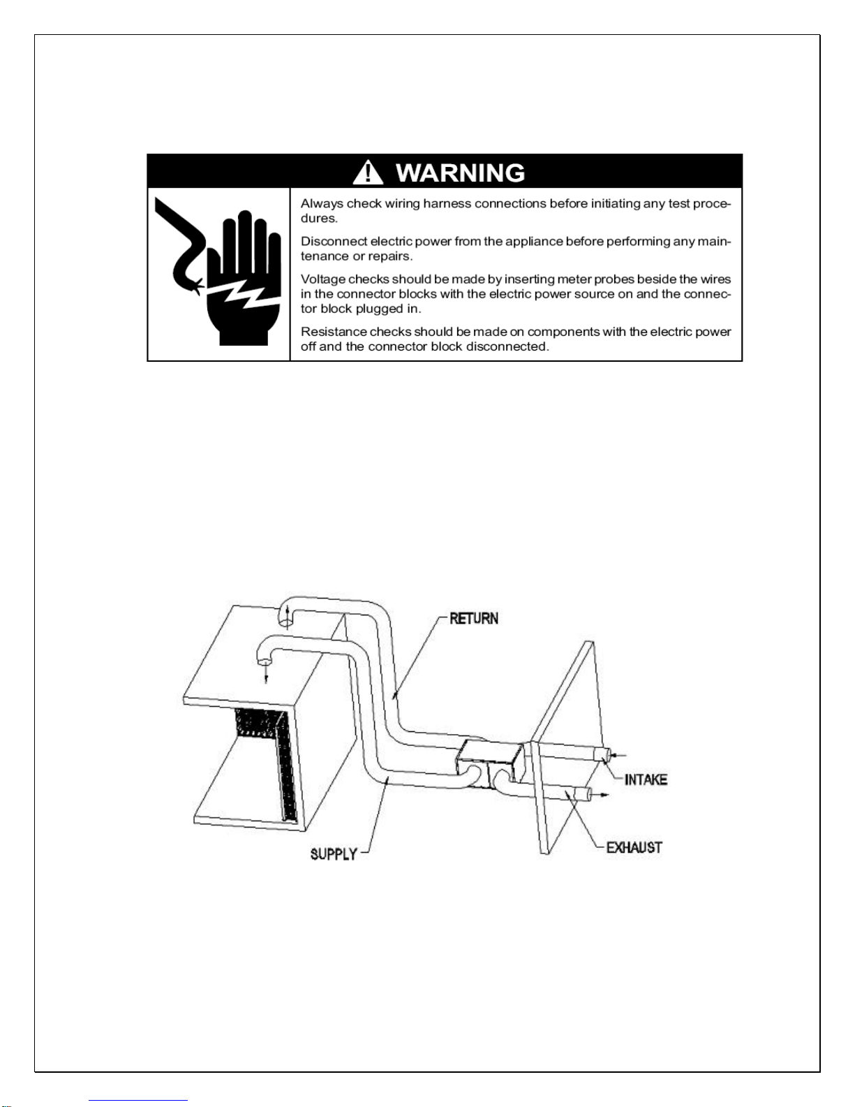
Fig. 3 DS System Installation
1. Location
• Place the unit in a properly ventilated location. If it is not, heat exhausted
by the condensing unit will build up and the cooling system will not operate
properly.
• Cooling unit shall be elevated to avoid possible flooding and shaded from
direct sun. It shall not be exposed to temperatures higher than 110 °F or
lower than 50 °F (optional low ambient kit available).
• Leave minimum 5 feet clearance for hot air exhaust and leave minimum 1
foot clearance for the fresh air intake.
• There is a gravity drain line and the unit shall be installed level or with a
slight angle toward the drain connection.
• Supply air flow shall be unobstructed for at least 12” for free installation or
2” for deflector installation and return air shall be unobstructed for 6”.
• Overall combined supply + return or exhaust + intake duct length can be
up to 50 ft long.
2. Mounting
• The unit must be mounted on a floor or slab that is level and strong
enough to support up to 300lb.
• There are six ½” bolts required to secure the unit base.
3. Customer Wiring
• Use 14 AWG wires
• If it is VINO4500DS without low ambient kit, go to the next step. Connect
the wires in the outlet box of the condensing unit to the power lines
• Connect the wires in the outlet box of the evaporator unit to the
temperature controller and then connect the controller to the power lines.
4. Air Sensor and Temperature Controller
• The air sensor is recommended to place in the wine room 5 ft above the
floor but not air dead area.
• If it is in a return duct, the evaporator fans shall be running all the time.
Due to the temperature differential the temperature setting needs to be
adjusted in order to maintain the proper wine room temperature.
• If the temperature controller is mounted away from the air sensor, use 18
gauge wires to extend the air sensor if needed.
5. Air Flow (Evaporator unit)
• It is necessary to check the air flow to meet the specified CFM. It may use
fan speed control to adjust the system refrigeration performance to
achieve 8-10
room temperature is maintained 55
°F differential between return air and supply air while wine
°F. Turn the control knob clockwise to
decrease the air flow or counter-clockwise to increase the air flow.
- 7 -
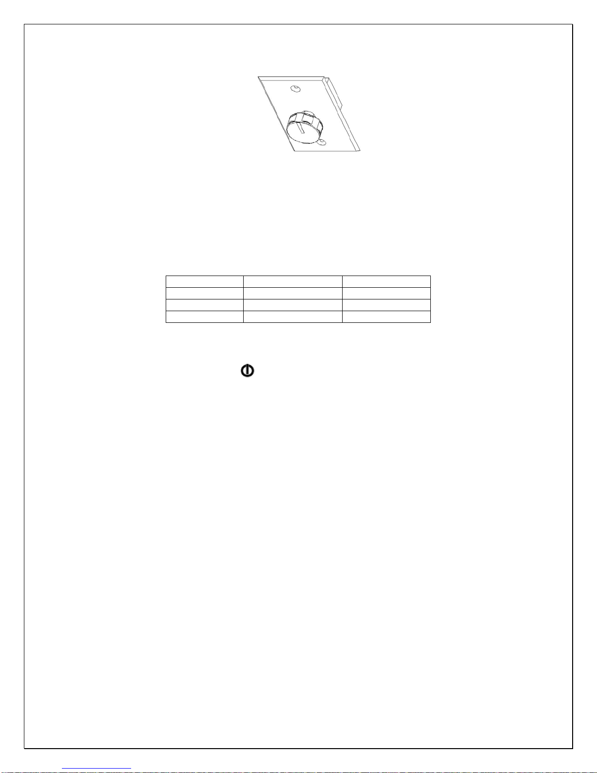
Fig. 4 Fan Speed Control
6. Intake and Exhaust Guards
• If the intake and exhaust are located outdoor, protection guards may be
required.
MODEL INSULATED DUCT DRAIN LINE
VINO-4500DS 8” DIA 7/8” OD
VINO-6500DS 10” DIA 7/8” OD
VINO-8500DS 10” DIA 7/8” OD
7. Unit Operating
• Turn on the fan speed control.
• Press digital controller to turn on the unit.
CAUTION:
IF THE CONDENSING UNIT IS EQUIPPED WITH A LOW AMBIENT
CONDITION KIT, DO NOT TURN ON THE COMPRESSOR UNTIL THE
CONDENSING UNIT HAS BEEN POWERD FOR 24 HOURS.
l
- 8 -
Temperature Control & Humidity Adjustment
1. Temperature Setting
• Set the temperature at 55
• On initial start-up, the time required to reach the desired temperature
will vary, depending on the quantity of bottles, temperature setting
and surrounding temperature.
• Allow 24 hours to stabilize the temperature for each new temperature
setting operation
1. Use of the controller
°F for the optimum aging of wine
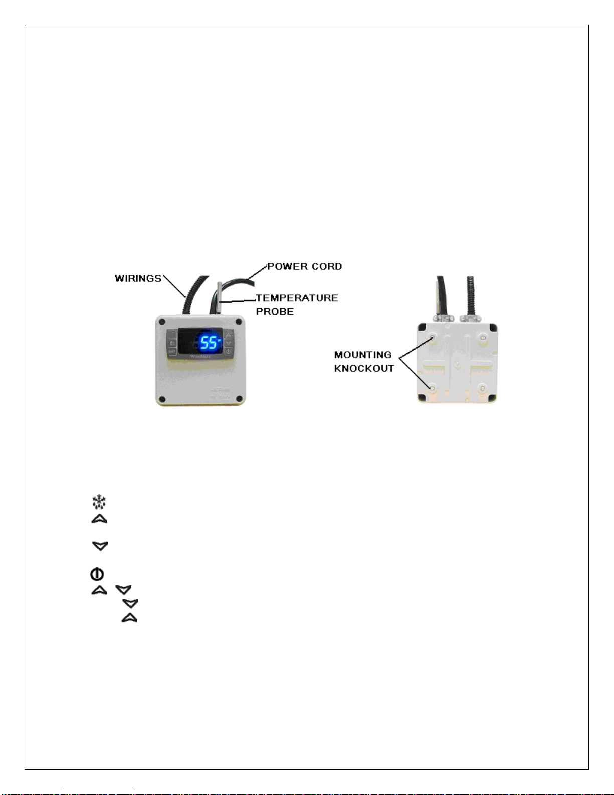
Fig. 5 Digital Controller (4.25”L X 3.75D X 4.25”H)
1) Keys
SET: To display target set point; in programming mode it selects a parameter or
confirm an operation.
(DEF): To start a manual defrost.
(UP): To see the maximum stored temperature; in programming mode it
browses the parameter codes or increases the displayed value.
(DOWN): To see the minimum stored temperature; in programming mode it
browses the parameter codes or decreases the displayed value.
: To turn on/off the power to the unit.
+ : To lock/unlock the keypad.
SET+
SET+ : To return to the temperature display.
2) Display
During normal operating conditions, the display shows the value measured by
the air regulation probe. In case of active alarm, the temperature flashes
alternately to the code alarm.
: To enter in the programming mode.
- 9 -
 Loading...