

Vinotemp WINE-MATE WM-1500-HTD, WINE-MATE VINO2500HZD, WINE-MATE WM-8500HTD, WINE-MATE VINO6500HZD, WINE-MATE VINO4500HZD Use And Care Manual
...
WINE-MATE Cooling Unit
Use & Care Manual
VINO1500HZD
VINO2500HZD
VINO3500HZD
VINO4500HZD
VINO6500HZD
VINO8500HZD
VViinnootteemmpp IInntteerrnnaattiioonnaall CCoorrpp..
wwwwww..vviinnootteemmpp..ccoomm
wwwwww..wwiinneemmaattee..ccoom
m
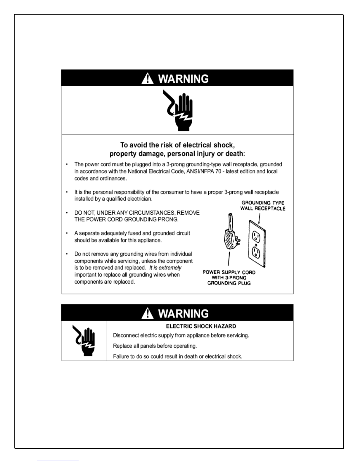
Important Safety Information
• DO NOT PLUG IN UNTIL 24 HOURS AFTER DELIVERY.
• DO NOT USE A GROUND FAULT INTERRUPTER (GFI).
• A DEDICATED 20 OR 30 AMPCIRCUIT IS REQUIRED (1500-4500HZD
OR 6500-8500HZD).
- 1 -

TABLE OF CONTENTS
Features & Specifications.…………………….……………..3
Installation Instruction………………………………………..5
Temperature Control & Humidity Adjustment...………..13
Care Guide…………………………………………………….16
Troubleshooting……………………………………………..17
Wiring Diagram……………………………………….………20
Customer Support……………………………………………21
Warranty……………………………………………………….22
- 2 -
Features and Specifications
• HZD cooling unit is designed and used to provide a stable temperature
between 50~65 °F for suitable space at a normal environment.
• The refrigerated space will maintain humidity of 50~70% RH even when
the environment becomes dry and humid.
• These temperatures and humilities are optimized for long term storage of
wine, fur and tobacco.
• Horizontal cold-air supply is optimized for use in the wide cabinets or wine
rooms.
• Self-contained ready for use and easy for installation
- 3 -
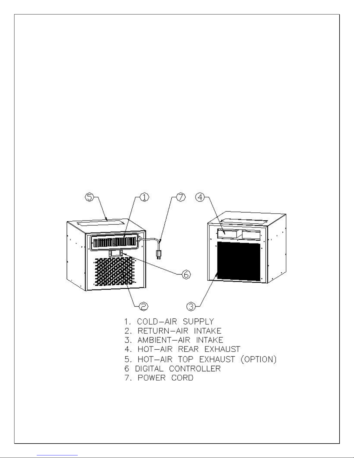
Fig. 1.1 FEATURE DESCRIPTIONS

Fig. 1.2 DIMENSIONS
The dimension and capacity are specified as follows:
MODEL CFM
VINO-1500HZD 120 90 14.25X16X13.25 115V/60HZ/4A 50
VINO-2500HZD 180 200 14.25X16X13.25 115V/60HZ/5A 55
VINO-3500HZD 250 650 14.25X21.25 X19.75 115V/60Hz/6A 75
VINO-4500HZD 250 1000 14.25X21.25 X19.75 115V/60Hz/9A 75
VINO-6500HZD 500 1500 17X28 X22 115V/60Hz/14A 110
VINO-8500HZD 500 2000 17X28 X22 115V/60Hz/16A 110
CAPACITY cu ft
°F/75°F)
(55
DIMENSIONS
W”XD”XH”
ELECTRICAL
WEIGHT
(lb)
NOTES:
• See the voltage, frequency and current specified on the label at the
cooling unit.
• Capacity is determined under the cabinet and ambient temperatures of
°F and 75°F with R11 interior and R19 exterior insulations. Any lower
55
cabinet and higher ambient temperatures will reduce the capacity.
- 4 -
Installation Instruction
Select a place to mount the unit where the exhaust airflow is unobstructed for a
minimum of 6 inch. The area into which the unit exhausts must be well ventilated.
If it is not, heat exhausted by the unit will build up and the unit will not operate
properly. The ambient temperatures shall not be higher than 78°F for a VINO-
1500HZD unit and 95°F for the other units or lower than 50 °F. Additionally, cold
supply air from the front grille must remain unobstructed. The unit shall be
mounted near the ceiling with equal distance from each side of the cabinet or
room.
The cooling unit produces cooling supplied into the cabinet, and it also generates
heat that must be exhausted outside the cabinet. So the cold supply side and hot
exhaust side must be separated and sealed. Foam tape may be used to seal
them. The cooling unit must intake adequate fresh ambient-air to work properly.
The ambient-air intake and warm-air exhaust must not be short-circulated. A
piece of wood may be used to separate them.
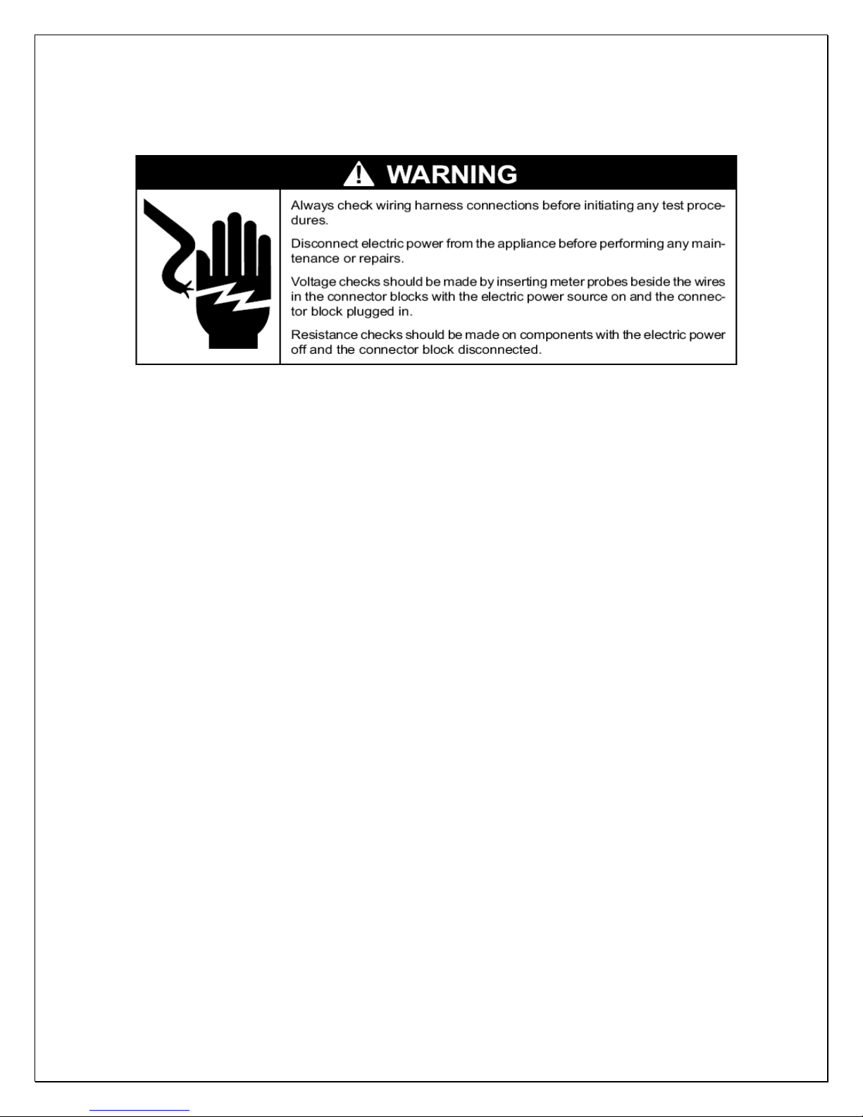
NOTES:
1) DO NOT INSTALL ANY DUCTS ONTO THE SUPPLY, INTAKE AND
EXHAUST.
2) MOUNTING BRACKETS, SCREWS, GASKETS AND OTHER SEAL
MATERIALS ARE NOT INCLUDED.
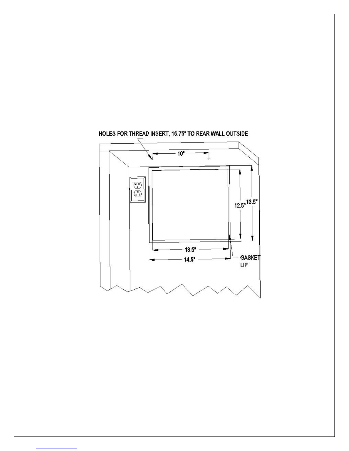
1. VINO1500-2500HZD CABINET INSTALLATION
• Cut a rectangular inside opening with the 1/4” clearance inwards to the
width and height of the cooling unit. By not going through, leave 1/2” lip
inside at the wall to place the gaskets (see Fig 2.1 & 2.2).
• If top exhaust, cut another rectangular opening at the top of the cabinet to
the length and width of the top exhaust.
• Make 2 holes at the ceiling to install the 1/4 inside diameter wood thread
inserts (see Fig.2.1 & 2.4).
• Place the gaskets (1/2” foam tape) on the mounting lip sides (see Fig 2.2).
- 5 -
• If top exhaust, place another gaskets along the top exhaust at the top of
the cooling unit (see Fig.2.3).
• Move the cooling unit towards the mounting sides and push to press the
gaskets (see Fig 2.5).
• Fasten the 2 brackets and use 7/16” wrench to tighten the two ¼” screws
(see Fig 2.6).
• Attach the exhaust and fresh air grille from the rear side of the cellar (see
Fig 2.7).
• Plug the cooling unit in receptacle.
• Plug the wine cellar.
Fig. 2.1 CABINET CUTOUT & GASKET LIP
- 6 -
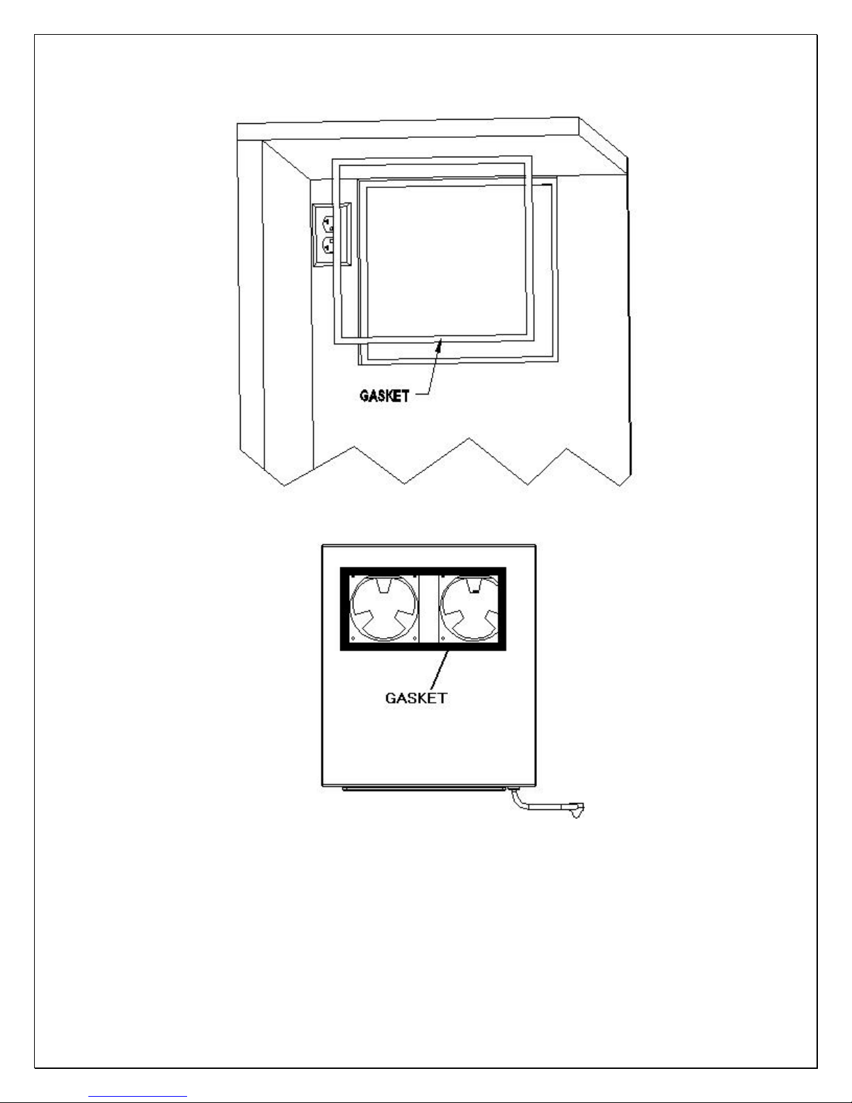
Fig. 2.2 GASKET
- 7 -
Fig. 2.3 TOP EXHAUST GASKET
 Loading...