

Vinotemp 1500CD, 2500CD, WineMate VINO1500CD, WineMate VINO1500CTED, WineMate VINO2500CD Use & Care Manual
...
WINEMATE Cooling Unit
Use & Care Manual
VINO1500CD, CTED
VINO2500CD, CTED
VViinnootteemmpp IInntteerrnnaattiioonnaall CCoorrpp..
wwwwww..vviinnootteemmpp..ccoomm
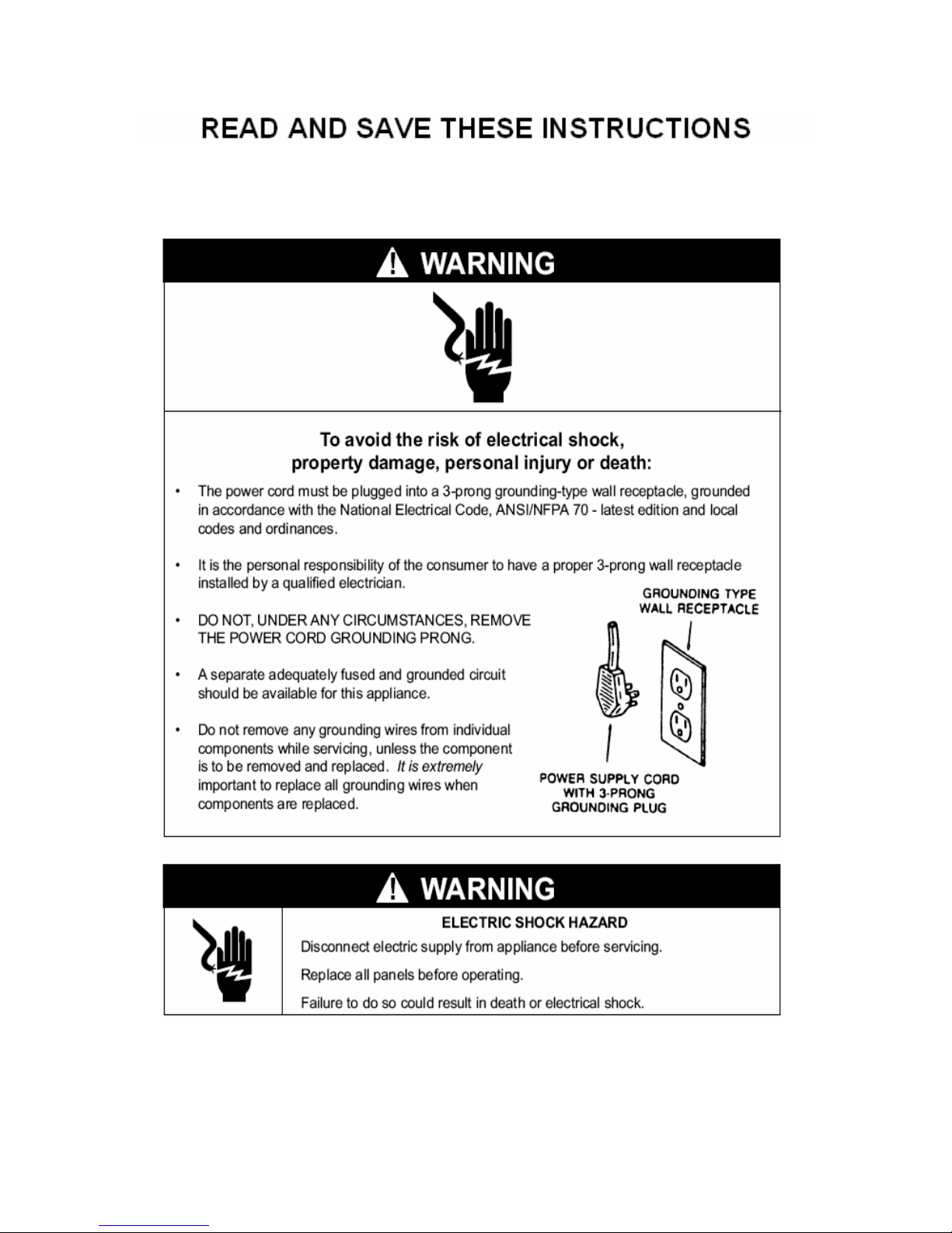
Important Safety Information
• DO NOT PLUG IN UNTIL 24 HOURS AFTER DELIVERY.
• DO NOT USE A GROUND FAULT INTERRUPTER (GFI).
• A DEDICATED 15 AMPCIRCUIT IS HIGHLY RECOMMENDED.
- 1 -

TABLE OF CONTENTS
Feature Description…………………………….……………..3
Installation Instruction………………………………………..5
Use and Temperature Control……………………………….7
Care Guide……………………………………………………10
Troubleshooting……………………………………………..12
Wiring Diagram……………………………………….………15
Customer Support……………………………………………16
Warranty……………………………………………………….17
Appendix……………………………………………………….19
- 2 -
Feature Description
• VINO1500CD, CTED and VINO2500CD, CTED cooling units are designed
and used to provide a stable temperature between 50~65 °F for suitable
space at a normal environment.
• The refrigerated space will maintain humidity of 50~70% RH even when
the environment becomes dry and humid.
• These temperatures and humilities ar e optimized for long term storage of
wine.
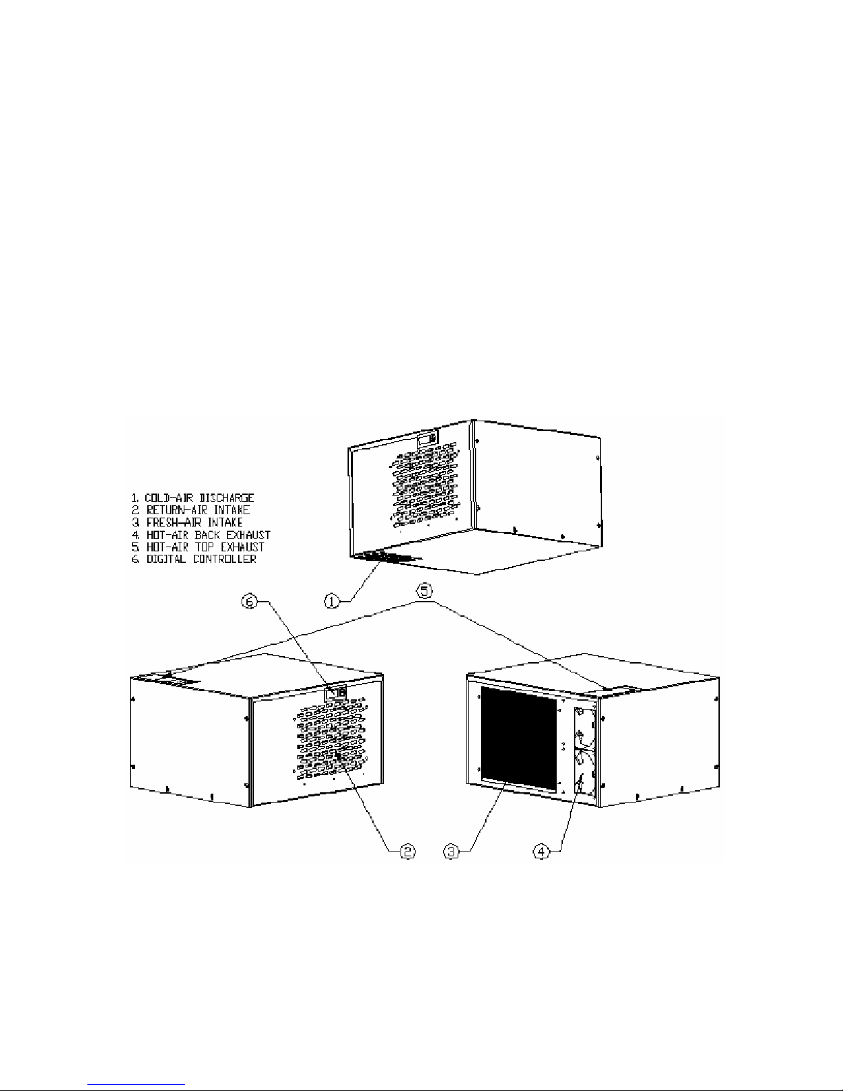
• Multiple exhaust for top and rear hot air exhaust
• Self-contained ready for use and easy for installation
- 3 -
Fig. 1.1 FEATURES
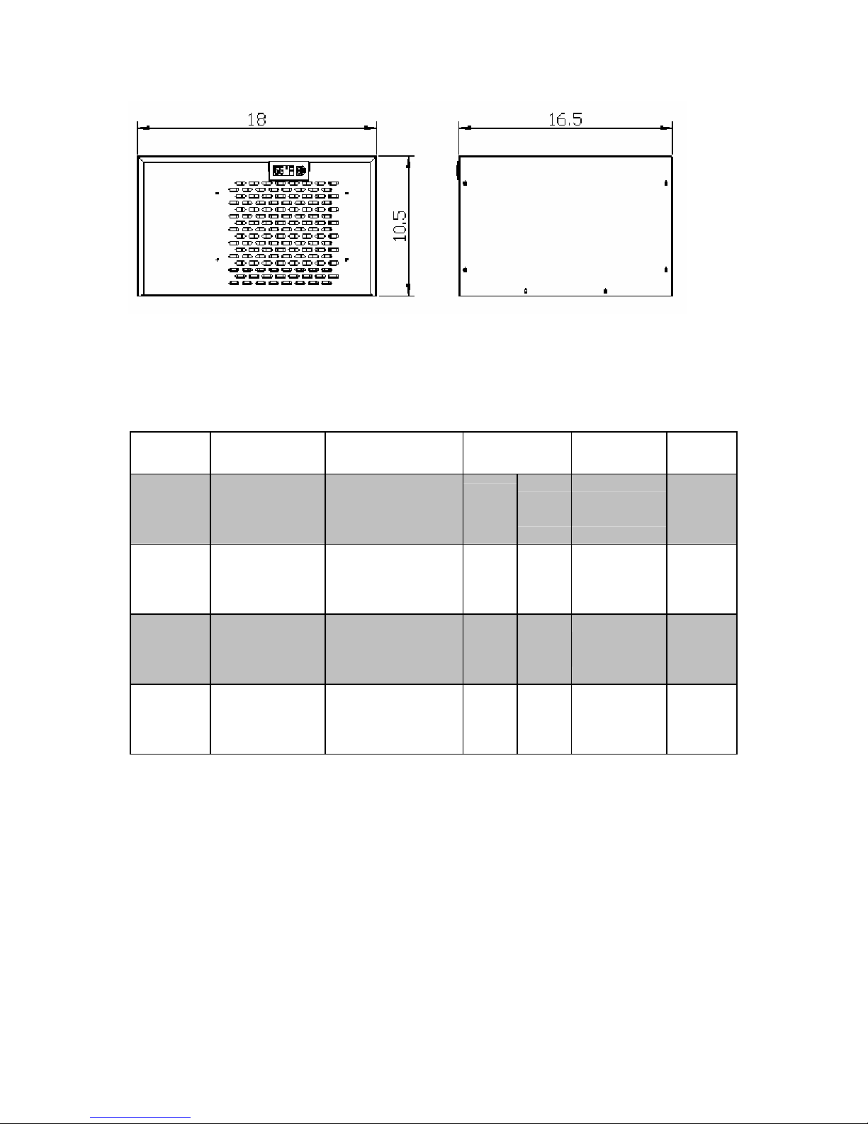
Fig. 1.2 DIMENSIONS
The dimension and capacity are specified as follows:
Model Description
1500cd
1500cted Top Exhaust
2500cd Rear Exhaust
2500cted Top Exhaust
Rear Exhaust
Cooling
Capacity
1500Btu/h
55°F Air Temp/
75°F Ambient
Temp
1500Btu/h
55°F Air Temp/
75°F Ambient
Temp
2500Btu/h
55°F Air Temp/
75°F Ambient
Temp
2500Btu/h
55°F Air Temp/
75°F Ambient
Temp
Wine
Capacity
Up to
150 cu
Up to
150 cu
Up to
250 cu
Up to
250 cu
ft
ft
ft
ft
bottles
bottles
1200
bottles
1200
bottles
800
800
Electrical Weight
115V/60Hz
4A
115V/60Hz
5A
115V/60Hz
4A
115V/60Hz
5A
• See the voltage, frequency and AMP from the label on the back of the
cooling unit.
50 lb
50 lb
55 lb
55 lb
- 4 -
Installation Instruction
1. Location
• Place the wine cabinet in a properly ventilated location. Otherwise, heat
exhausted by the cooling unit will build up and it will not operate properly.
• The exhaust area must not be closed space and must be ventilated.
1) Rear Exhaust
• Leave min 6 “clearance from the rear to the wall.
• Leave min 12” clearance from the top to the ceiling.
• Leave min 6” clearance from the left and right sides.
2) Front Exhaust
• Leave min 6” clearance from the front if left and right sides unobstructed.
• Or, leave min 36” clearance from the front if left and right sides obstructed
3) Top Exhaust
• Leave min 12” from the top to the ceiling.
• Leave min 2 “clearance from the rear to the wall.
• Leave min 2” clearance from the left and right sides.
4) Side Exhaust
• Leave min 6 “clearance from the left or right side to the wall.
• Leave min 12” clearance from the top to the ceiling.
2. Installation
- 5 -
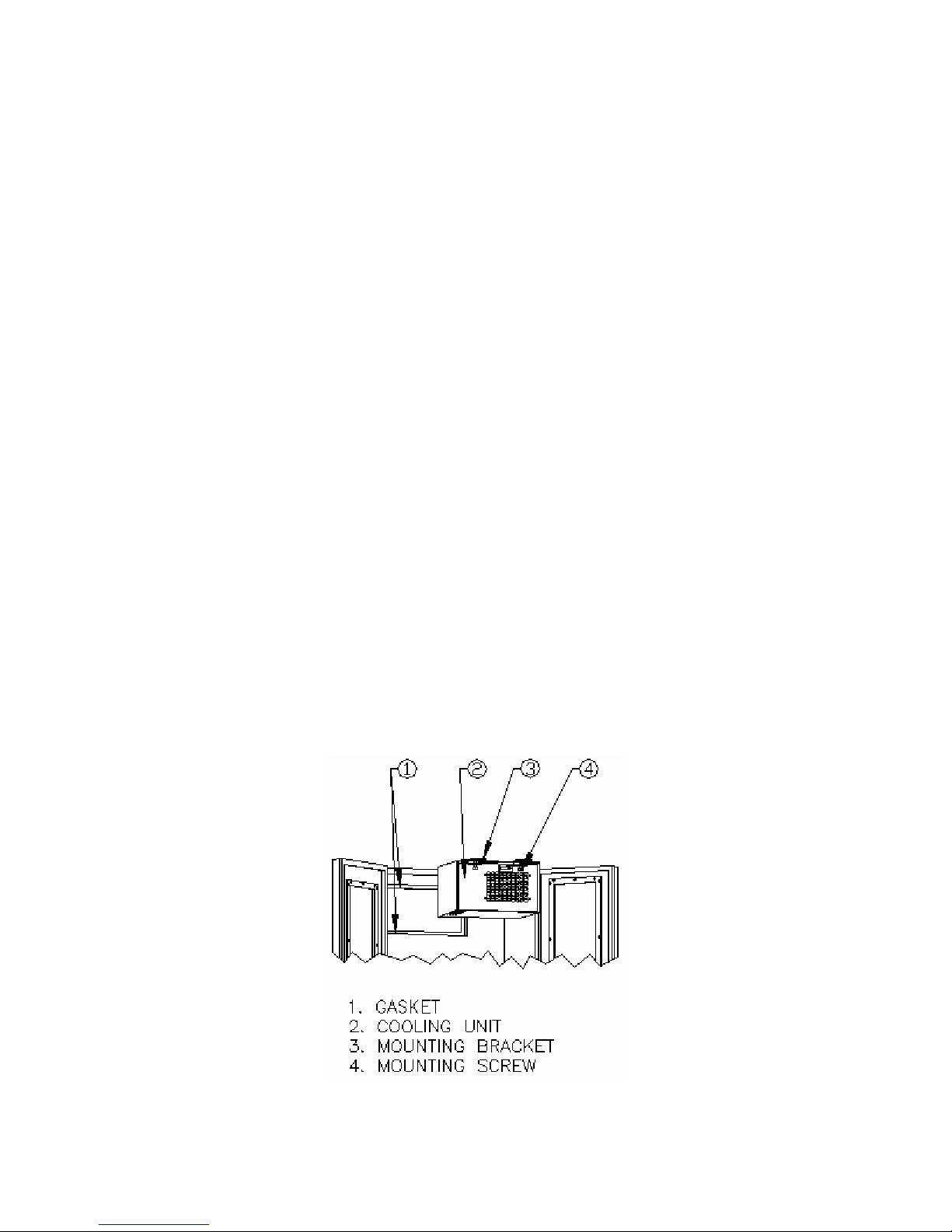
Fig. 2.1 COOLING UNIT MOUNTING
 Loading...