

Vinotemp Wine-Mate VINO4500SSR, Wine-Mate VINO2500-4500SSR, Wine-Mate VINO2500-2500SSR, Wine-Mate VINO2500-6500SSR, Wine-Mate VINO2500SSR Installation & Operation Manual
...
wwwwww..wwiinneemmaattee..ccoomm
WINE-MATE Split System
Installation, Operation & Care Manual
VINO2500SSR VINO4500SSR VINO6500SSR
VViinnootteemmpp IInntteerrnnaattiioonnaall CCoorrpp..
READ AND SAVE THESE INSTRUCTIONS
wwwwww..vviinnootteemmpp..ccoomm

TABLE OF CONTENTS
Important Safety Information…..........................................2
Features & Specifications.…………………….……………..3
Cellar Construction.…………………………….……………..6
Installer’s Instruction…………….…..….……..……………..8
Electrical Wiring...……………..…..….……..………………15
Temperature Control & Humidity Adjustment.………….19
Care Guide…………………………………………………….22
User’ Troubleshooting…….………………………………...23
Customer Support……………………………………………26
Warranty……………………………………………………….27
- 1 -
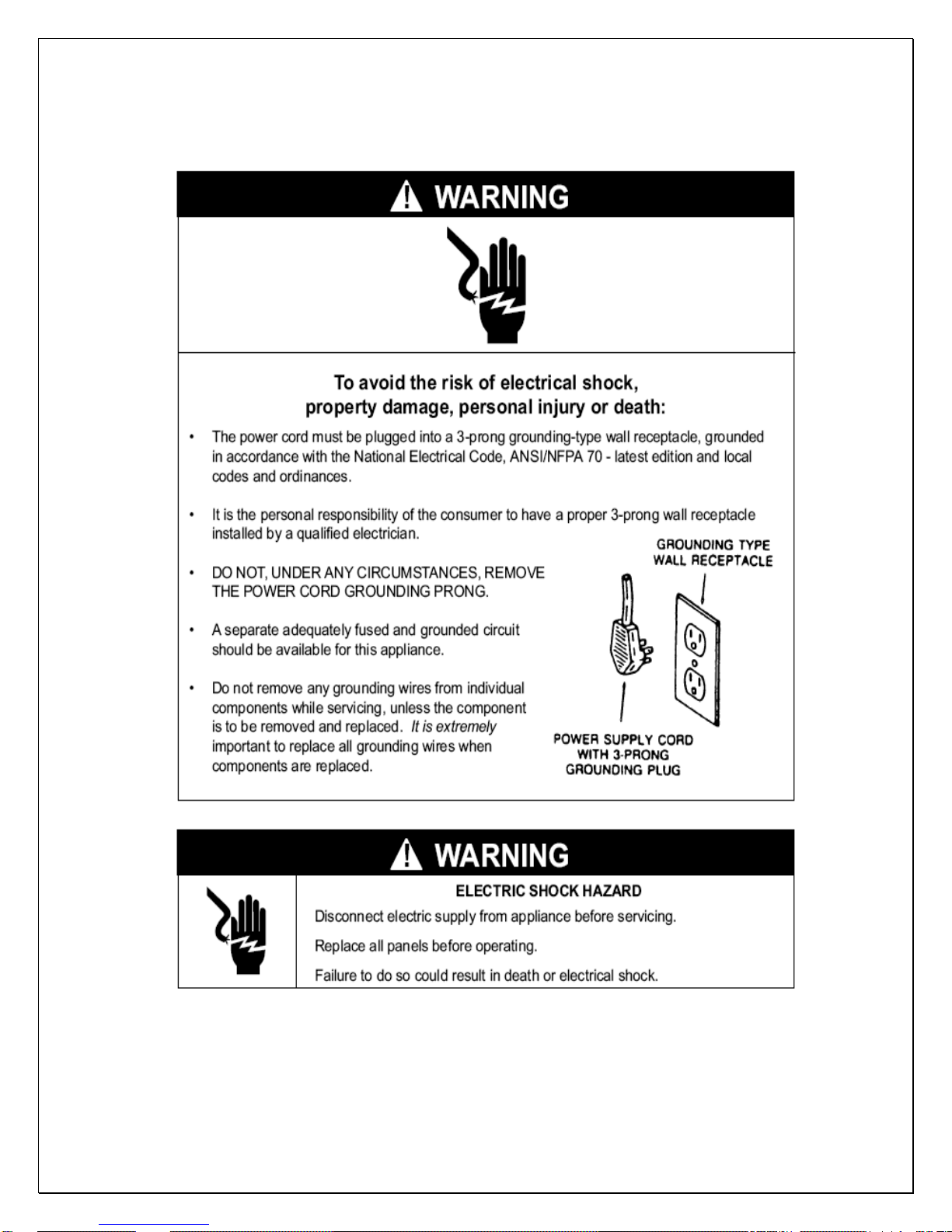
Important Safety Information
WARNING:
• DO NOT USE A GROUND FAULT INTERRUPTER (GFI).
• A DEDICATED 20 OR 30 AMP CIRCUIT IS REQUIRED (2500-4500SSR OR
6500SSR).
- 2 -
MODEL
VINO-
2500SSR
VINO-
4500SSR
VINO-
6500SSR
Features and Specifications
• Wine-Mate split cooling systems VINO2500-6500SSR are designed and
used to provide a cold temperature between 50~65
insulated wine room at a normal environment.
• The wine room will maintain humidity of 50~70% RH even when the
environment becomes dry and humid. These temperatures and humilities
are optimized for long term storage of wine.
• SSR units consist of a condensing unit and an evaporator unit, and they
are connected by a liquid line and an insulated suction line.
• SSR condensing units can be located away from the evaporator units and
wine cellars as far as 50 ft, which will bring you quiet operation.
• The SSR evaporator units are designed for installation inside a wine rack
or between two ceiling joists, making them an ideal choice for small and
medium wine rooms. There are also multiple air inlet and outlet doors for
different installations.
The dimensions and capacities are specified as follows:
EVAP UNIT
L”xD”xH”
WM-
25SFCR
30x11.125
x11.375
WM-
45SFCR
36x11.125
x14.375
WM-
65SFCR
42x11.125
x14.375
COND UNIT
L”xD”xH”
WM-250SCU
18x12x14
WM-450SCU
18x12x14
WM-650SCU
24x18 x17
Btu/h, CFM
(55/90°F)
2500/220 250 cu ft R134a
4500/335 1000 cu ft R134a
6500/420 1500 cu ft R134a
CAPACITY
(55/75°F)
REFRIGERANT
NOTE:
CAPACITY IS DETERMINED UNDER THE CELLAR AND AMBIENT
TEMPERATURES OF 55
°F AND 75°F WITH R11 INTERIOR AND R19
EXTERIOR INSULATIONS. ANY LOWER CABINET AND HIGHER AMBIENT
TEMPERATURES WILL REDUCE THE CAPACITY.
CAUTION:
LOW AMBIENT TEMPERATURE KIT IS REQUIRED IF THE INSTALLATION
AREA WILL BE BELOW 50
°F.
CAUTION:
LIQUID AND SUCTION LINES MAY DIFFER FROM WHAT ARE SHOWN
HERE, PLEASE CHECK ON THE UNITS FOR PROPER INSTALLATION.
°F for a properly
ELECTRICAL
EVAP UNIT/
COND UNIT
115V-60HZ-
0.77A /115V60HZ-5.7A
115V-60HZ-
0.77A /115V60HZ-6.9A
115V-60HZ-
1.9A /115V60HZ-12A
WEIGHT(lb)
EVAP UNIT/
COND UNIT
26/40
35/60
43/60
- 3 -
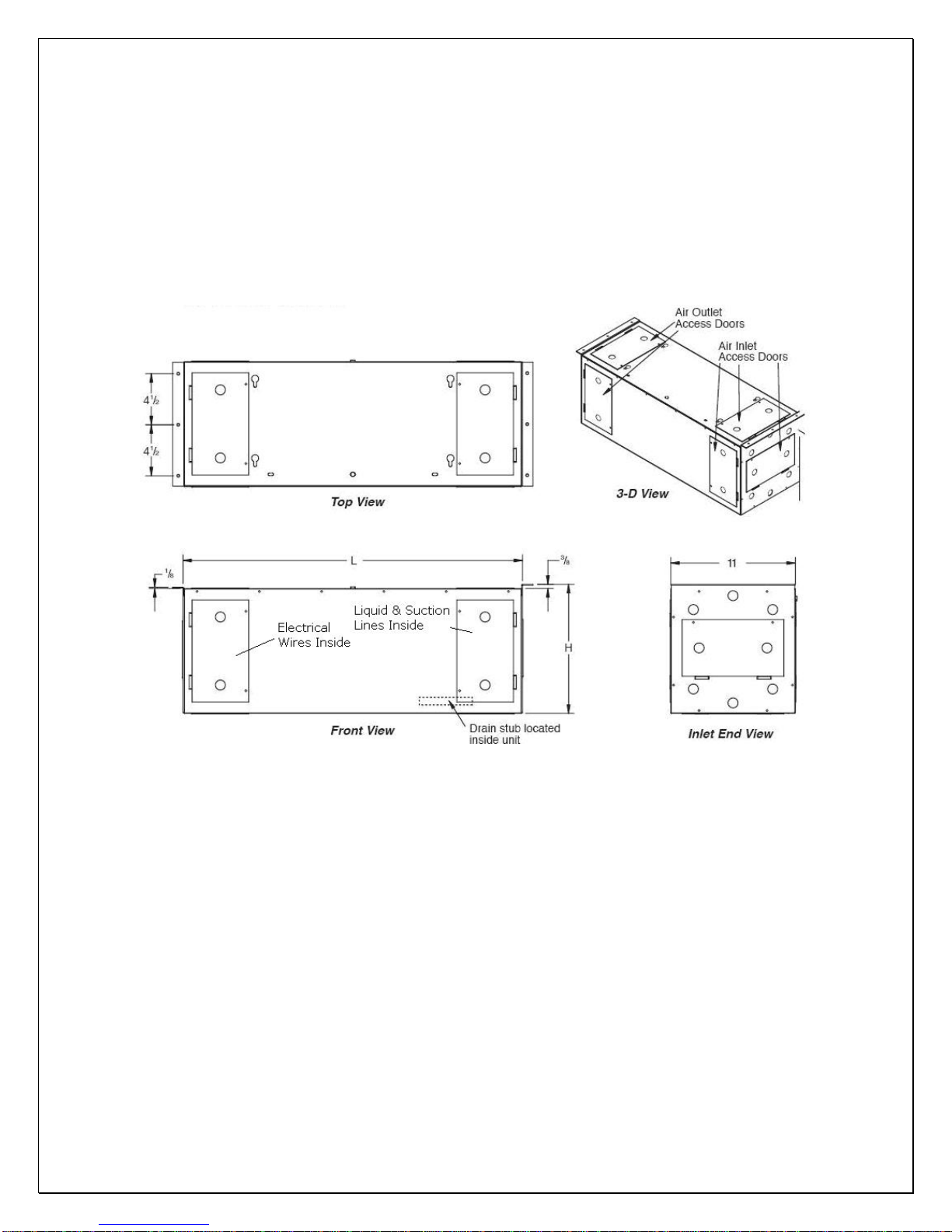
NOTE:
LEAVE MINIMUM 3” CLEARANCE FOR ELECTRICAL WIRING AND
REFRIGERATION PIPING.
Parts included:
Condensing Unit (discharge and suction valves installed) + Liquid Filter + Liquid
Indicator
Evaporator Unit (liquid line solenoid valve and expansion valve installed)
Temperature Controller + Air Sensor
Fig. 1 WM25-65SFCR Evaporator Unit
- 4 -
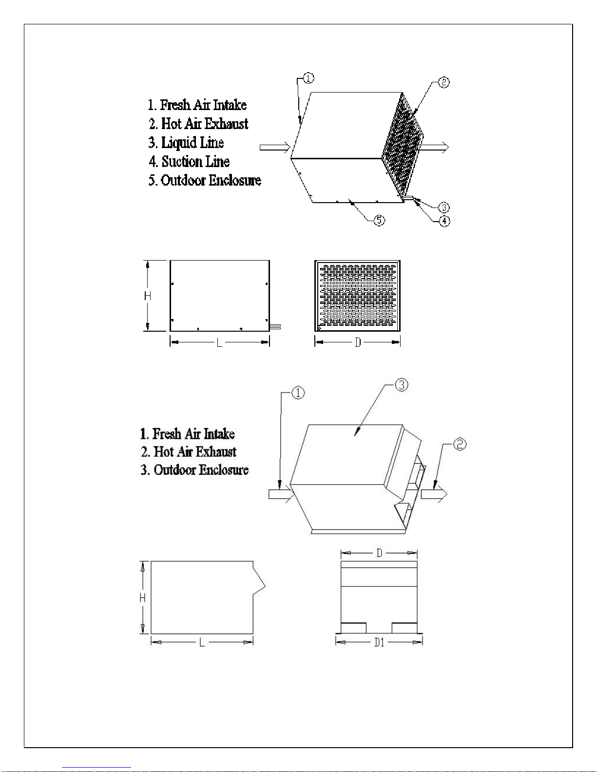
Fig. 2 WM250-450SCU Condensing Unit
- 5 -
Fig. 3 WM650SCU Condensing Unit
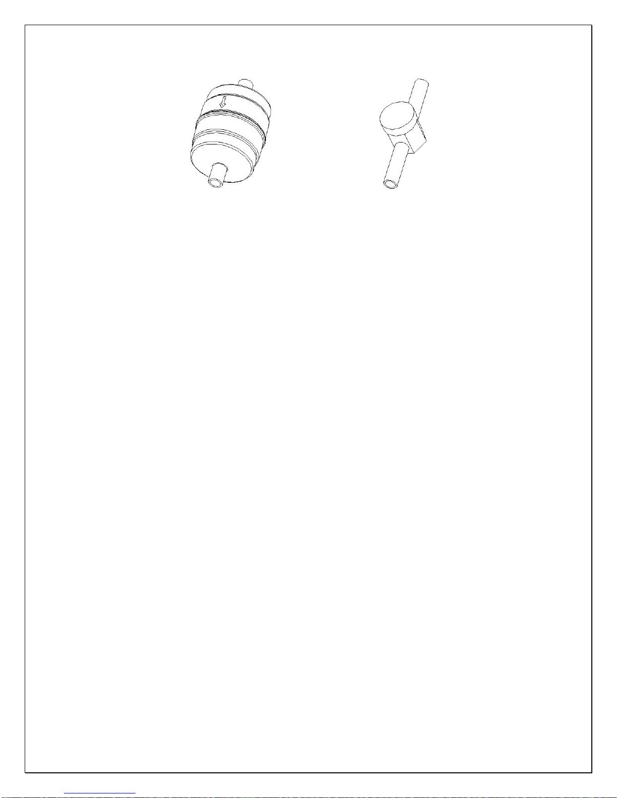
Fig. 4 Liquid Filter Fig. 5 Liquid Indicator
- 6 -
Cellar Construction
This is only a guide and shall be considered as minimum requirements.
All interior walls and floors shall have a vapor barrier and a minimum of R11
insulation. All exterior walls and ceiling shall have a vapor barrier and a minimum
of R19 insulation. The vapor barrier shall be installed on the warm side of the
insulation. All joints, door frames, electrical outlets or switches and any pipes or
vents that go through the enclosure shall be sealed to prevent air and moisture
leakage into the room. Concrete, rock, and brick are not insulation or vapor
barriers.
Doors shall be of a minimum size, insulated to at least R11 and tightly sealed
with high quality weather stripping. Be sure to seal the bottom of the door and fill
gap between the door’s frame and wall before installing the cap molding.
In order to maintain 55 °F in the wine cellar, the ambient temperature
surrounding the enclosure shall not exceed the temperature of the enclosure by
more than 25 °F. No enclosure wall shall receive direct sun or strong wind.
Lighting shall be of low wattage, with a timer to insure lights are not left on when
the enclosure is not occupied.
The cooling system will not be able to maintain the proper temperature if fresh
moisture-laden air is constantly being introduced to the enclosure. Symptoms of
this condition are; unit runs all the time with only a slight reduction in temperature
and/or water overflows from the unit. Because of the temperature difference
between the inside and outside, very small cracks can allow large amounts of
outside air to enter into the enclosure. Please be aware that moisture can pass
through solid concrete, paint and wood. Often a newly constructed room contains
fresh wood, paint, concrete and other building materials. These materials contain
large amounts of moisture. When placed into operation in this type of
environment, the system will work harder to remove this extra moisture resulting
in increased “run” time.
- 7 -
Installer’s Instruction
Federal law requires that WINE-MATE split cooling systems be
installed by an EPA certified refrigeration technician.
WINE-MATE split system is shipped as components and is ready for use only
after a certified refrigeration technician has properly installed, evacuated,
charged and tested the system. Proper installation is critical. Vinotemp can only
warrant the quality of the components. The installation and proper operation of
the system must be warranted by the installer. Installation of the system must be
done in accordance with all state and local building and electrical codes.
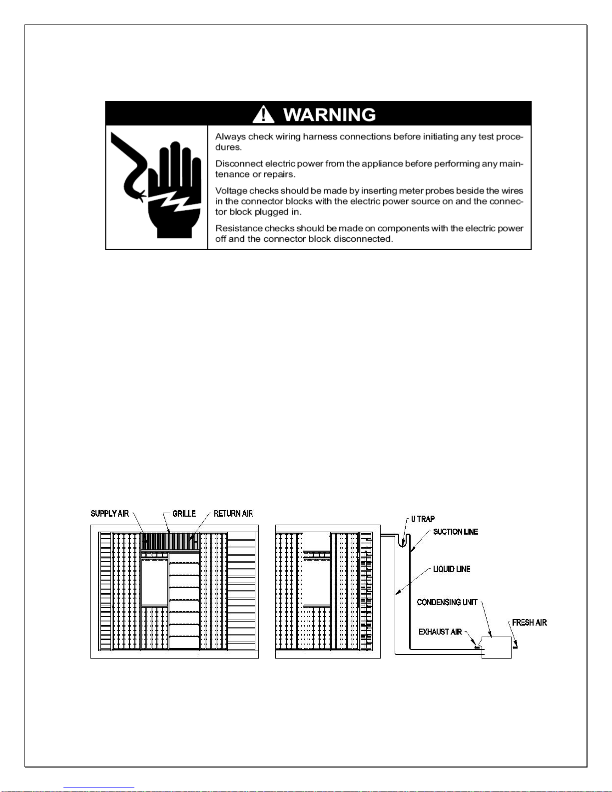
The condensing unit and evaporator unit are connected by a liquid line and an
insulated suction line that are supplied by the installer. These lines must be
properly sized for the distance between the two units. After the units and the lines
are installed, the system must be pressure tested. If no leaks are found,
evacuate and charge system. Refrigerant amount will vary depending on the
length of line set.
- 8 -
Fig. 6 VINO-SSR Installation
 Loading...