

Vinotemp WINEMATE VINO-1500SS, WINEMATE VINO-1900SS Installation Instructions Manual
VINO1500SS VINO1900SS
Installer’s Instruction
Federal law requires that WINEMATE split cooling systems be
installed by an EPA certified refrigeration technician.
WINEMATE split system is shipped as components and is ready for use only
after a certified refrigeration technician has properly installed, evacuated,
charged and tested the system. Proper installation is critical. Vinotemp can only
warrant the quality of the components. The installation and proper operation of
the system must be warranted by the installer. Installation of the system must be
done in accordance with all state and local building electrical codes.
The condensing unit and evaporator unit are connected by a liquid line and an
insulated suction line that are supplied by the installer. These lines must be
properly sized for the distance between the two units. After the units and the lines
are installed, the system must be pressure tested. If no leaks are found,
evacuate and charge system. Refrigerant amount will vary depending on the
length of line set.
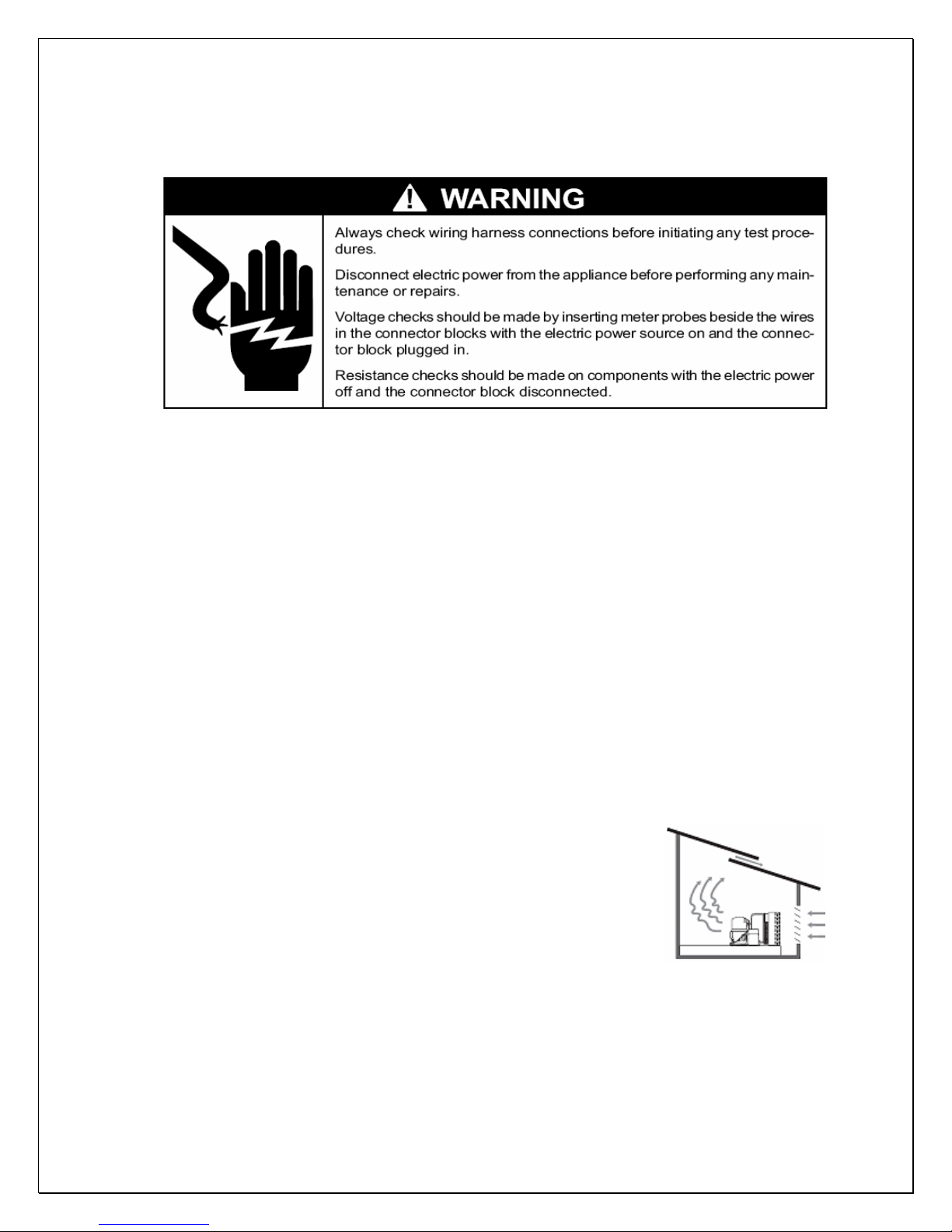
1. Condensing Unit
• Place the condensing unit in a properly ventilated
location. If it is not, heat exhausted by the condensing
unit will build up and the cooling system will not
operate properly.
• Condensing unit shall be elevated to avoid possible
flooding and shaded from direct sun. It shall not be
exposed to temperatures higher than 110
than 50 °F (optional low ambient kit available).
• Leave minimum 5 feet clearance for the exhaust side and leave minimum
1 foot clearance for the fresh air intake side.
°F or lower

CAUTION:
DO NOT SWITCH ON THE COMPRESSOR IF THE CONDENSING UNIT IS
EQUIPPED WITH A LOW AMBIENT CONDITION KIT UNTIL THE UNIT HAS
BEEN PLUGGED IN FOR 24 HOURS.
2. Valve Operation (Condensing unit)
BACK POSITION FRONT POSITION MIDDLE POSITION
Fig. 1 ROTALOCK Valve Operation
BACK POSITION FRONT POSITION MIDDLE POSITION
Fig. 2 Base Valve Operation
1 - Process & Manometer; 2 - Receiver/Compressor Suction
3 - Liquid/Suction Line; 4 - Pressure Control
Back Position: Process and manometer port closed for normal operation
Front Position: Connection to liquid or suction line closed
Middle Position: All ports open for evacuation, charge and manometer reading
3. Evaporator Unit
• The WM-15SFC evaporator units shall be installed for ceiling mount with
the air supply towards horizontally and air return on the bottom.
• The WM-19SFC evaporator unit shall be ins t alled for wall mount with the
air supply towards top and air return on the sides.
• Supply and return air flow from the evaporator unit shall be unobstructed
for at least 1 foot.
- 1 -
 Loading...