

Vinotemp Wine-Mate WM-2520SSW, Wine-Mate 2520SSW-LA, Wine-Mate 4520SSW-LA, Wine-Mate WM-4520SSW Care & Installation Manual
Split Wall-Recessed Cooling System
Operation Care Installation Manual
WM-2520SSW 2520SSW-LA
WM-4520SSW 4520SSW-LA
wwwwww..vviinnootteemmpp..ccoomm
RReeaadd aanndd ssaavvee tthheessee iinnssttrruuccttiioonnss
Vinotemp International Corp
17631 S Susana Road Rancho Dominguez, CA 90221
Tel: (800) 777-VINO Fax: (310) 886-3310 Email: info@vinotemp.com
- 1
-
Important Safety Information

- 2
-
Table of Contents
Cellar Construction Guide------------------------------------------3
Features & Specifications------------------------------------------4
Temperature & Humidity--------------------------------------------6
Care Guide-------------------------------------------------------------10
User’ Troubleshooting---------------------------------------------11
Installer’s Instructions---------------------------------------------14
Electrical Wirings----------------------------------------------------25
Warranty----------------------------------------------------------------27

- 3
-
Cellar Construction Guide
This is only a guide and shall be considered as the minimum requirements.
All interior walls, ceilings and floors shall have a vapor barrier and a minimum of
R13 insulation. All exterior walls and ceiling shall have a vapor barrier and a
minimum of R19 insulation. The vapor barrier shall be installed on the warm side
of insulation. All joints, door frames, electrical outlets or switches and any pipes
or vents that go through the cellar shall be sealed to prevent air and moisture
leaking into the cellar. Concrete, rock, and brick are not insulations or vapor
barriers. Doors shall be of a minimum size, insulated to at least R13 and tightly
sealed with high quality weather stripping. Be sure to seal the bottom of the door
and fill gap between the door’s frame and wall before installing the cap molding.
In order to maintain 55 °F in the wine cellar, the ambient temperature
surrounding the cellar shall not exceed the temperature of the cellar by more
than 25 °F. No cellar walls shall receive direct sun or strong wind.
Lighting shall be of low wattage, with a timer to insure lights are not left on when
the cellar is not occupied.
The cooling system will not be able to maintain the proper temperature if fresh
moisture-laden air is constantly being introduced to the cellar. Symptoms of this
condition are; cooling unit runs all the time with only a slight reduction in
temperature and/or water overflows from the cooling unit. Because of the
temperature difference between the inside and outside, very small cracks can
allow large amounts of outside air to enter into the cellar. Please be aware that
moisture can pass through solid concrete, paint and wood. Often a newly
constructed cellar contains fresh wood, paint, concrete and other building
materials. These materials contain large amounts of moisture. When placed into
operation in this type of environment, the system will work harder to remove this
extra moisture resulting in increased “run” time.
- 4
-
Features and Specifications
WINE~MATE split wall-recessed cooling systems WM-2520~4520SSW and
WM-2520~4520SSW-LA are designed to provide a cold environment between
50~65 °F with a humidity range within 50~70% RH for a properly insulated
wine cellar.
These temperature and humidity ranges are optimized for long term storage
of wine like that in natural caves.
SSW evaporator units can be installed inside a wine rack or between two wall
studs, making them an idea choice for wine cabinets or small wine rooms as
built-in installation
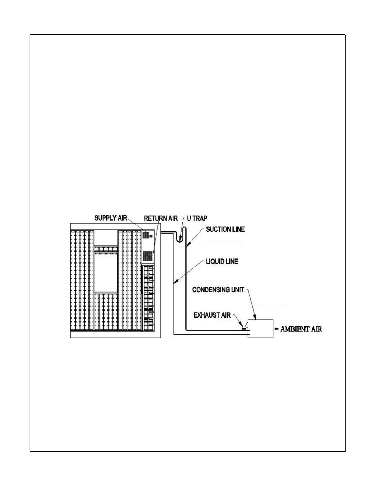
SSW cooling systems consist of a remote condensing unit and an evaporator
unit and they are connected by a liquid line and an insulated suction line.
SSW condensing units can be located away from the wine cellars up to 75 ft
so that noise and compressor vibration are isolated.
Fig. 1 SSW Split Wall-Recessed Cooling System
- 5
-
CAUTION
If the condensing unit will operate below 50°F, install a low
ambient condition kit.
NOTE
The cooling capacity is determined under 55°F cellar
temperature, 75°F cellar ambient temperature and 90°F
condensing unit ambient temperature, with R13 interior and
R19 exterior insulations. Higher ambient temperatures or
lower insulations will cause reducing capacity and the cellar
temperature may not be maintained at 55°F.
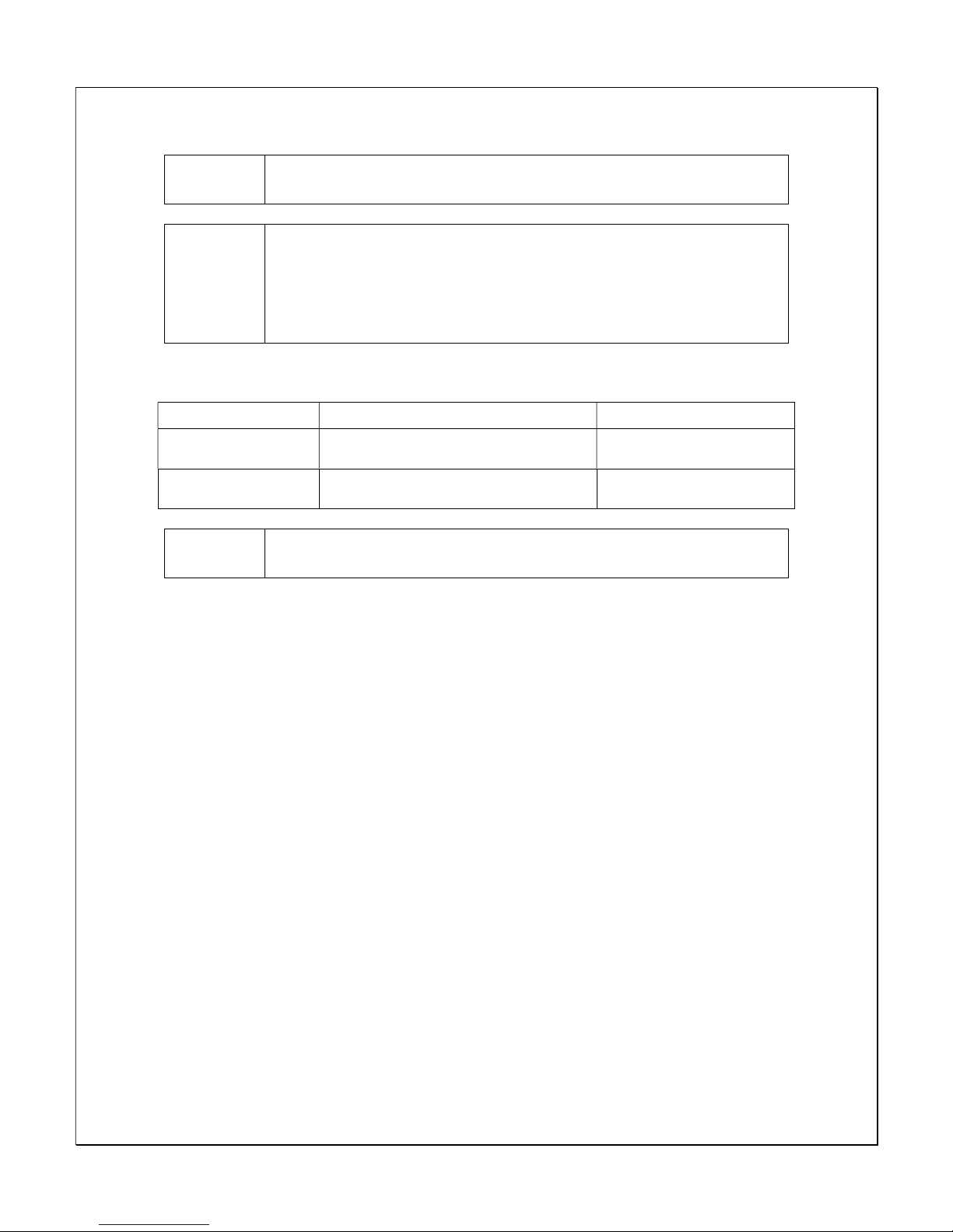
The specifications are listed as follows:
Model No. Capacity (Btu/h) / Airflow (CFM) Max Cellar Size (cu ft)
WM-2520SSW
WM-2520SSW-LA
2100 / 150 230
WM-4520SSW
WM-4520SSW-LA
3700 / 200 900
NOTE
“LA” refers the unit equipped with low ambient kit.
For further info, see Fig. 3~7.
- 6
-
Temperature and Humidity
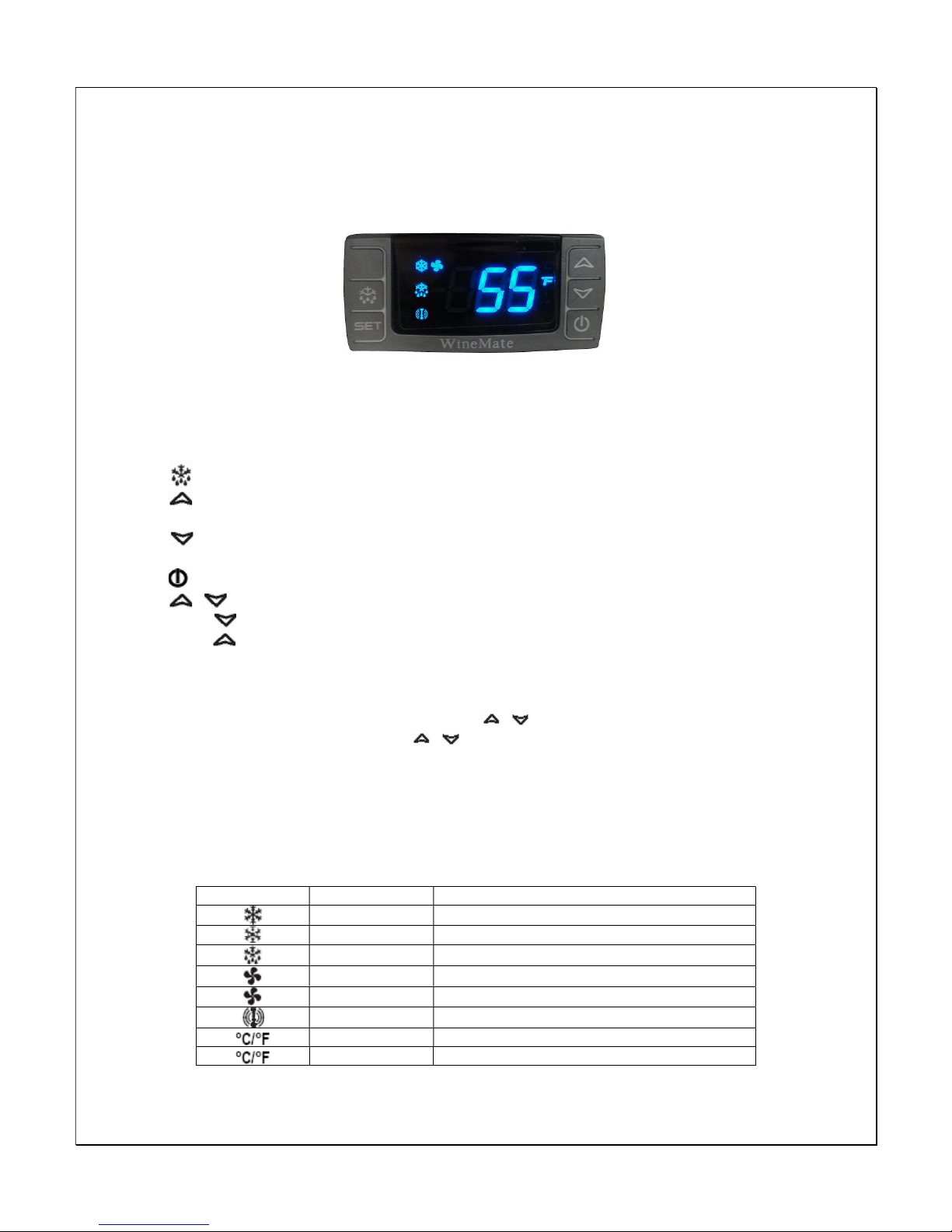
1. The controller
Fig. 2 TEMPERATURE CONTROLLER
1) Keys
SET: To display set-point; in programming mode it selects a parameter or
confirms an operation.
: To start a manual defrost.
: To see the maximum stored temperature; in programming mode it browses
the parameter codes or increases the displayed value.
: To see the minimum stored temperature; in programming mode it browses
the parameter codes or decreases the displayed value.
: To turn on/off the power to the unit.
+ : To lock/unlock the keypad.
SET+ : To enter in the programming mode.
SET+ : To return to the temperature display.
2) Lock and unlock the keys
To lock the keys, press up + down keys + until POF is displayed; to unlock
the keys, press up + down keys + until PON is displayed.
3) Display
During normal operating conditions, the display shows the value measured by
the air temperature probe. In case of active alarm, the temperature flashes
alternately to the code alarm. The LED functions are listed as follows.
LED
MODE
FUNCTION
ON Compressor enabled
Flashing Anti-short cycle enabled
ON Defrost enabled
ON Fan enabled
Flashing Fan delay after defrost enabled
ON Alarm occurring
ON Temperature measuring unit
Flashing
Programming mode
- 7
-
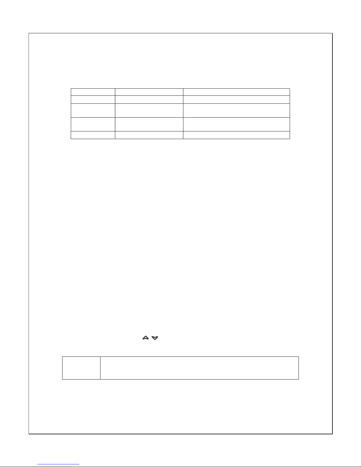
4) Alarm Signals
The alarm codes are described as follows.
MESSAGE
CAUSE
FUNCTION
P1
Temperature probe faulty Compressor switching to Con and CoF
HA
High temperature alarm
Probe temperature ALU higher than the
setting temperature; Outputs unchanged
LA
Low temperature alarm
Probe temperature ALL lower than the
setting temperature; Outputs unchanged
CA
External alarm All outputs off
Probe alarms P1”, start a few seconds after the fault in the related probe; they
automatically stop a few seconds after the probe restarts normal operation.
Check connections before replacing the probe. Temperature alarms “HA”, “LA”
automatically stops as soon as the temperature returns to normal value. Alarm
“CA” (with i1F=PAL) recovers only by switching off and on the instrument.
2. Temperature Setting
Set the temperature at 55 °F for the optimum aging of wine
On initial start-up, the time required to reach the desired temperature will
vary, depending on the quantity of bottles, temperature setting and
surrounding temperature.
Allow 24 hours to stabilize the temperature for each new temperature setting
operation
3. How to see temperature set-point
1) Press and immediately release the SET key, the display will show the set-point
value.
2) Press again and immediately release the SET key to display the probe value.
4. How to change the set-point
1) Press and hold the SET key until the “°C” or “°F” LED starts flashing and the
set-point is displayed.
2) Press the up/down keys / to change the set-point value within 10 sec.
3) Press the SET key again to store the new set-point value.
NOTE
The unit turns on at set-point Set plus regulation differential Hy
after anti-short cycle AC has elapsed; the unit turns off at set-point
Set.
- 8
-
5. Manual Defrost
Press and hold the defrost key until defrost starts. The defrost indicator will be
on.
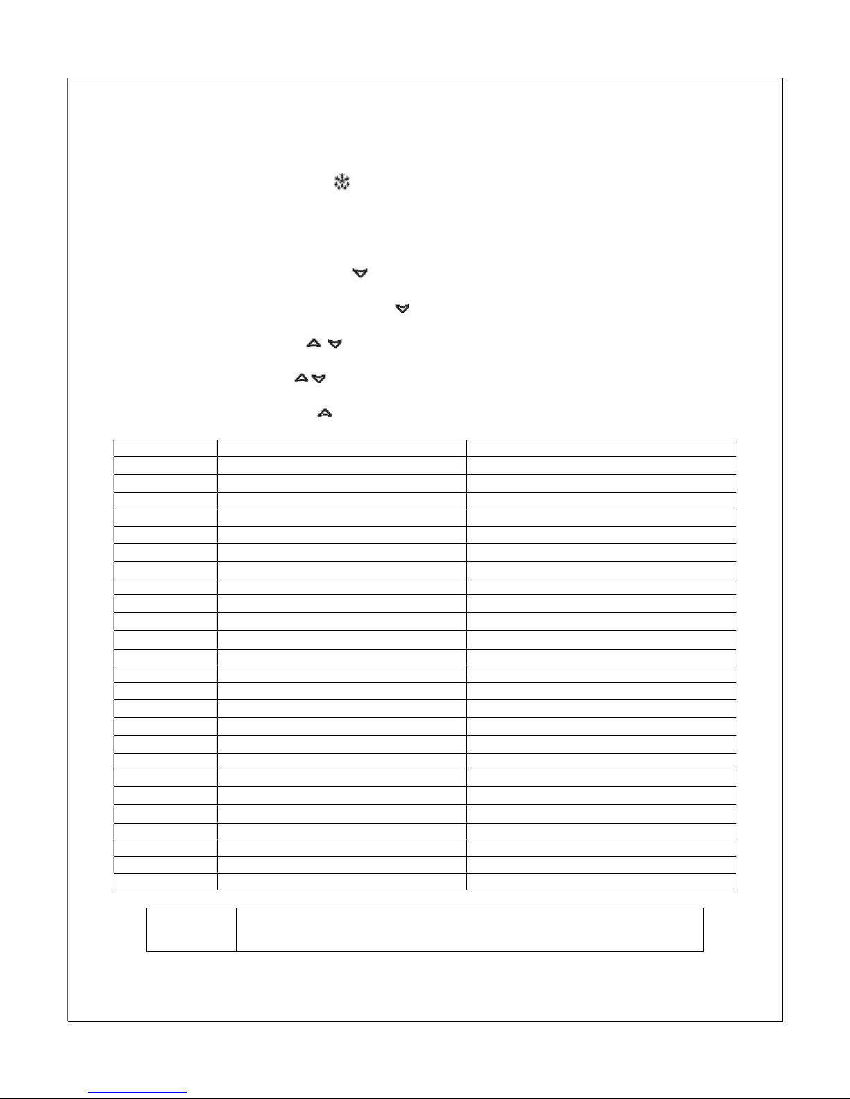
6. Parameter Programming
1) Press and hold the SET + keys until the “°C” or “°F” LED starts flashing,
then release the keys.
2) Press and hold again the SET + keys until the Pr2 label is displayed, then
release the keys. The first parameter Hy will be displayed.
3) Press up/down keys / to scroll to the required parameter within 10 sec.
4) Press the “SET” key to display its value.
5) Use up/down keys to change its value within 10 sec.
6) Press “SET” to store the new value and the display will flash 3 times.
7) To exit: Press SET + or wait 15sec without pressing a key.
PARAMETER
DESCRIPTION DEFAULT VALUE
Set
set-point (°)
55
Hy
temperature regulation differential (°)
4
AC anti-short cycle delay (min)
10
(hidden)
Con compress on with
probe faulty (min)
15
CoF compress off with probe faulty (min)
30
CF
temperature unit (
°F/ °
C)
F: Fahrenheit
rES display resolution
in: integer
dLy temperature display delay (min)
1
ot
probe calibration (°)
0
LS
minimum set-point (°)
50
US
maximum set-point (°)
65
idF defrost interval time (hour)
12
MdF defrost endurance time (min)
30
ALC
temperature alarm type
rE: relative to set
-
point
ALU
high temperature alarm (°)
10
ALL
low temperature alarm (°)
10
AFH
alarm recovery differential (°)
5
ALd temperature alarm delay (min)
60
dAO temperature alarm delay on startup (hr)
23
SAA
heater set-point (°)
40
SHy
heater regulation differential (°)
4
FSU fan action
Std
FnC fan operating mode
C-
n: on with compressor & off during defrost
Fon fan
on with compressor off (min)
0
FoF fan off with compressor off (min)
15
NOTE
Depending on the controller, not all parameters are available
 Loading...