

Vinotemp 4500DS, 8500DS, 6500DS, WineMate VINO4500DS, WineMate VINO6500DS Installation, Operation & Care Manual
...Page 1
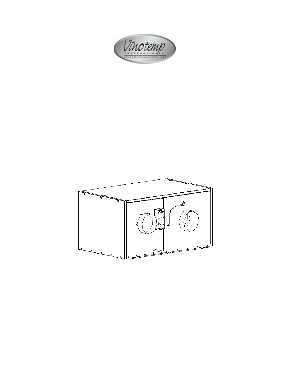
WINEMATE Ducted System
Installation, Operation & Care Manual
VINO4500DS
VINO6500DS
VINO8500DS
VViinnootteemmpp IInntteerrnnaattiioonnaall CCoorrpp..
wwwwww..vviinnootteemmpp..ccoomm
Page 2
TABLE OF CONTENTS
Important Safety Information…..........................................2
Feature Description…………………………….……………..3
Installation Instruction………………………………………..6
Use and Temperature Control…………..…………………10
Care Guide……………………………………………………12
Troubleshooting……………………………………………..13
Customer Support……………………………………………15
Warranty……………………………………………………….16
- 1 -
Page 3
Important Safety Information
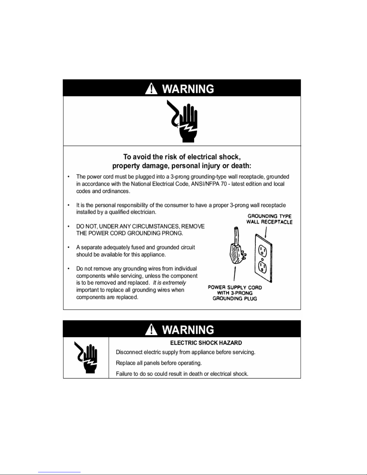
• DO NOT USE A GROUND FAULT INTERRUPTER (GFI).
• A DEDICATED 20 AMPCIRCUIT IS HIGHLY RECOMMENDED.
- 2 -
Page 4
Feature Description
• The WINEMATE ducted cooling system is designed and used to provide a
stable temperature between 55~65 °F for a properly insulated room at a
normal environment.
• The wine room space will maintain humidity of 50~70% RH even when the
environment becomes dry or humid.
• These temperatures and humilities are optimized for long term storage of
wine, fur and tobacco.
• Ducted cooling systems are designed for both outdoor and indoor
installation.
• Back-curved impeller fans are good for 50 ft long duct use to cut the
operation noise.
• Self-contained ready for use with no extra tubing in field.
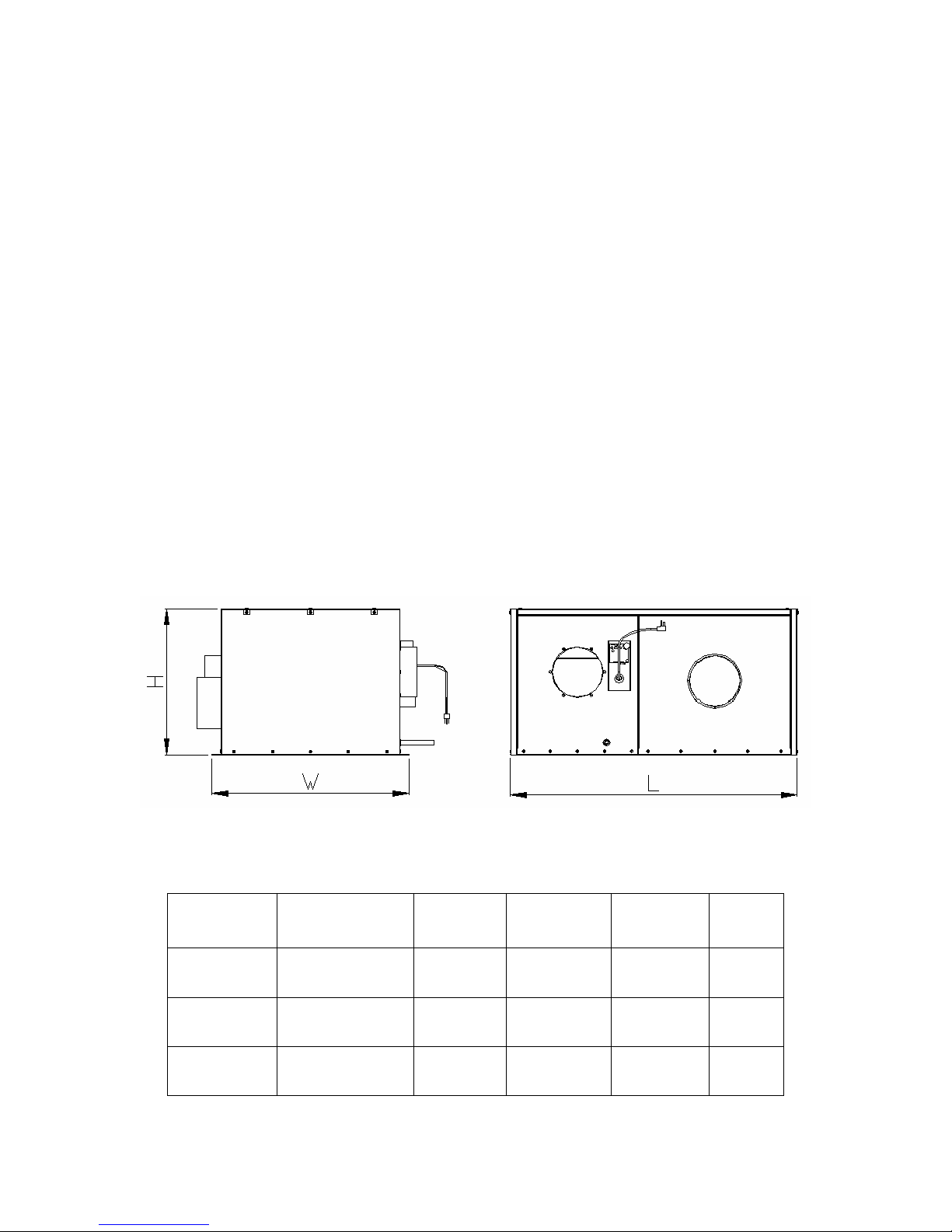
The dimension and capacity are specified as follows:
Model
VINO4500DS 4500
VINO6500DS 6500
VINO8500DS 8500
Capacity (Btu/h)
55/90°F
- 3 -
UNIT DIMENSIONS
Electrical
115V 60HZ
8A
115V 60HZ
14A
115V 60HZ
17A
Refrigerant L”XW”XH”
R134a 45X31X23 96
R134a 45X31X23 170
R134a 45X31X23 220
Weight
(lb)
Page 5
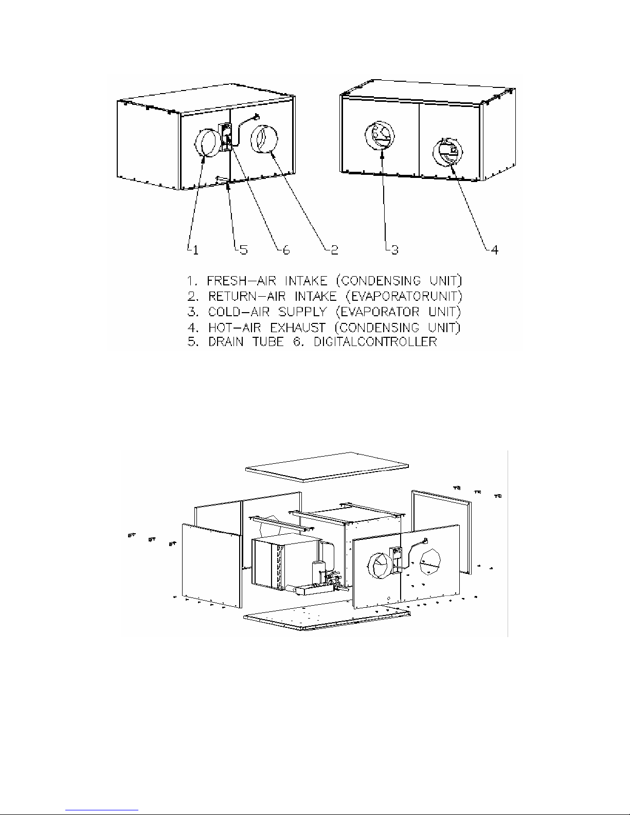
FEATURES
EXPLODED VIEW
- 4 -
Page 6
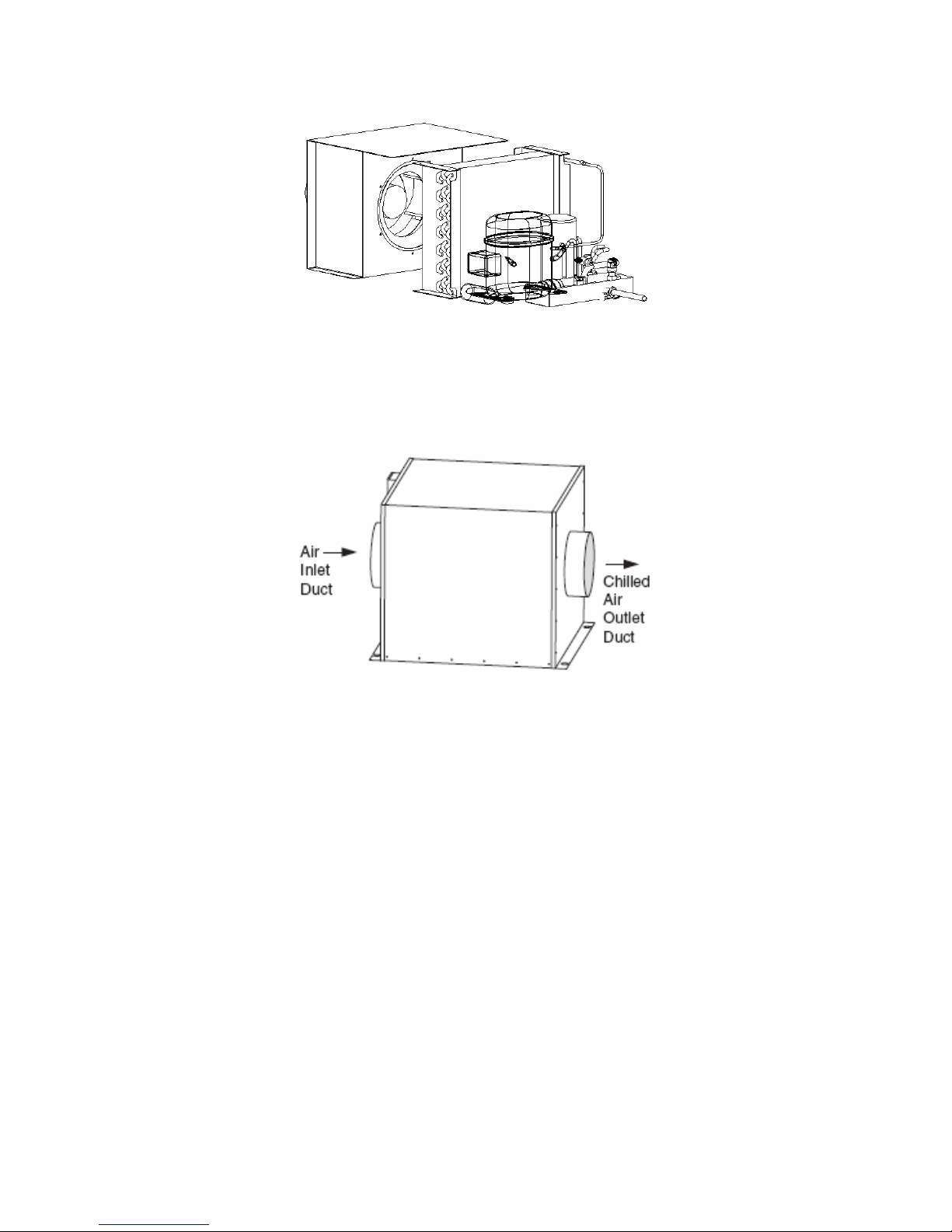
CONDENSING UNIT
EVAPORATOR UNIT
- 5 -
Page 7
Installation Instruction
1. Location
• WINEMATE ducted system is shipped ready for use
• Place the unit in a properly ventilated location. If it is not, heat exhausted
by the condensing unit will build up and the cooling system will not operate
properly.
• Leave minimum 3 feet clearance between the exhaust pipe and the wall.
• Leave minimum 1 foot clearance for the fresh air supply pipe.
• Air flow from the cold air discharge pipe should be unobstructed for at
least 1 foot.
• Unit should be elevated to avoid possible flooding and shaded from direct
sun. It should not be exposed to temperatures higher than 125 °F or lower
than 20 °F.
• Overall combined duct length can be up to 50 ft long.
2. Refrigeration Piping
Model
VINO4500DS 1/2 8
VINO6500DS 1/2 8
VINO8500DS 1/2 8
Drain Tube Diameter
3. Air Sensor
The air sensor is recommended to place in the wine room. If it is in a return duct,
the temperature differential may lead to erroneous readings.
(inch)
Air Pipe Diameter
(inch)
- 6 -
Page 8
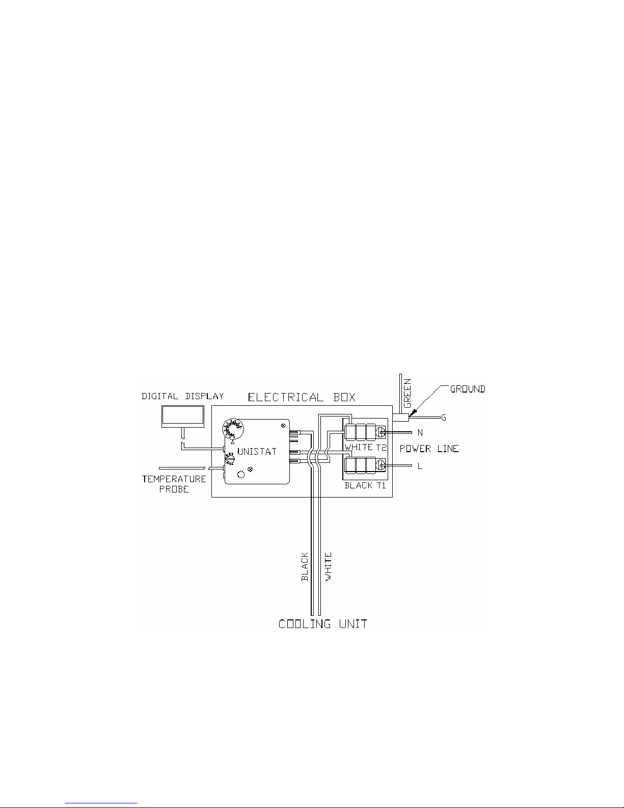
4. Electrical Wiring
• We strongly recommend against the use of an extension cord. However, if
you still select to use an extension cord, it is absolutely necessary that it is
a UL LISTED 3-wire grounding type appliance extension cord. The
marked rating of the extension cord should be 115 V, 20 A. or equivalent
and not greater than 15ft in length.
1) Customer Wiring
• If the air sensor can not reach the wine room because of the distance
between the cooling unit and wine room, you need to remount the
electrical box.
• Remove the 3 black, white and green wires that come from the cooling
unit in the electrical terminal
• Remove the electrical box and mount it close to the wine room so the air
sensor can reach the wine room
• Use extra wires to connect the terminal in the electrical box and the 3
white, black and green wires from the cooling unit.
- 7 -
Page 9
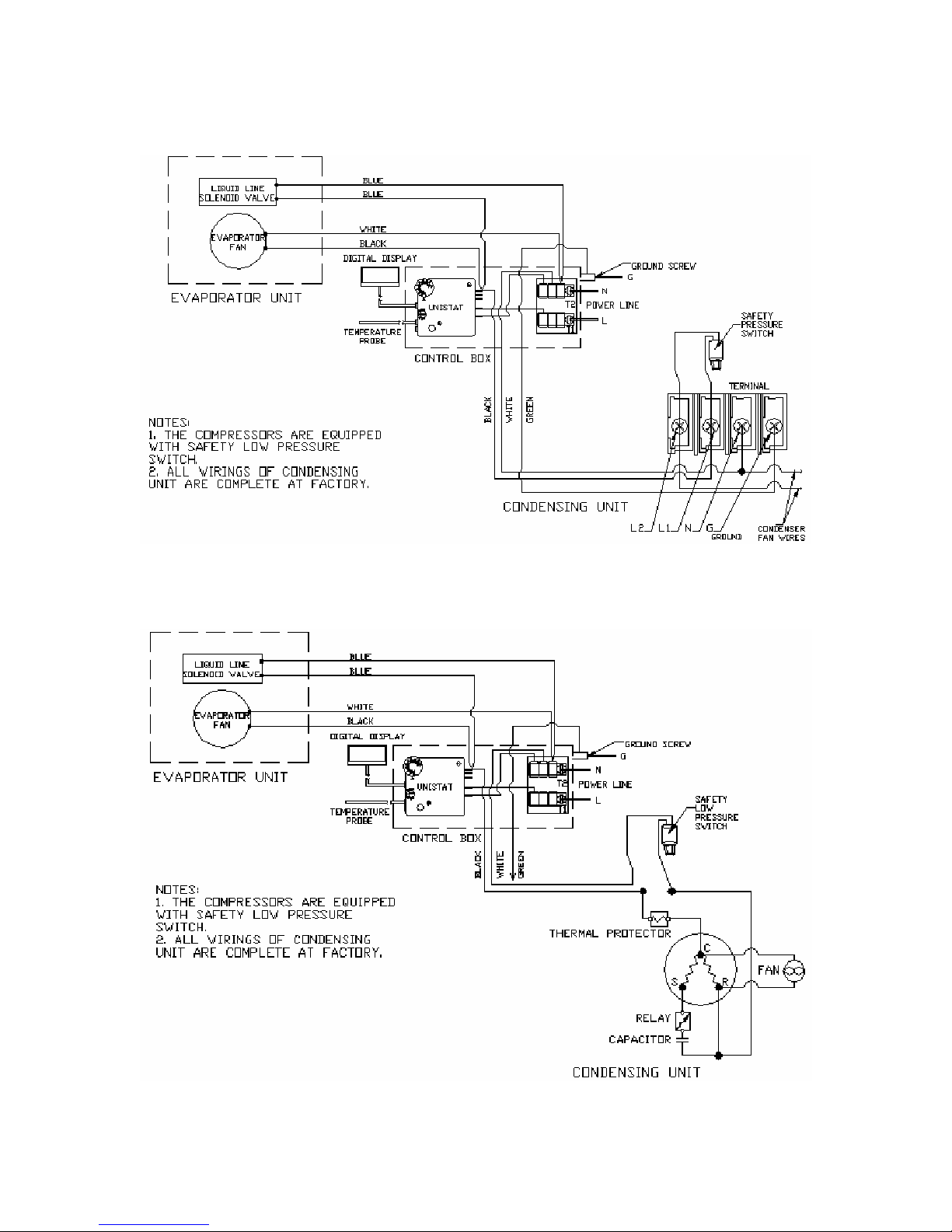
2) Factory Wiring
VINO4500DS Electrical Wiring Diagram
VINO6500DS Electrical Wiring Diagram
- 8 -
Page 10
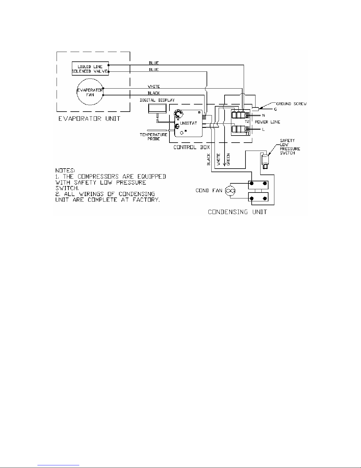
VINO8500DS Electrical Wiring Diagram
- 9 -
Page 11
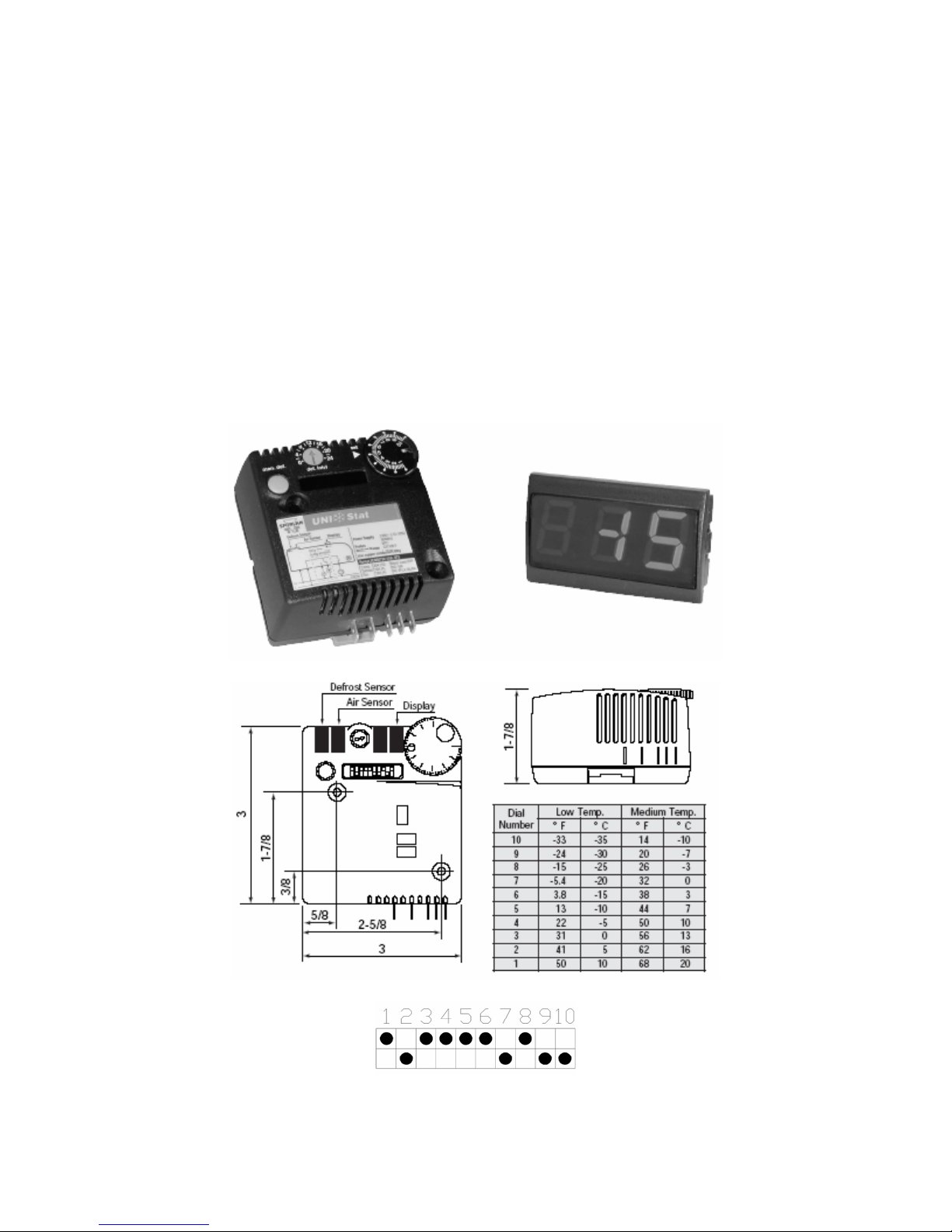
Use & Temperature Control
1. Temperature Setting
• Set the temperature at 55 °F for the optimum aging of wine
• On initial start-up, the time required to reach the desired temperature
will vary, depending on the quantity of bottles, temperature setting
and surrounding temperature.
• Allow 24 hours to stabilize the temperature for each new temperature
setting operation
2. Use of the controller
Dip Switch Setting
- 10 -
Page 12

1) Set Point
Rotate the circular selector in correspondence with the arrow placed nearby. The
selector represents -33°F to 50°F (-35°C to +10°C) for low temperature models,
and 14°F to 68°F (-10°C to +20°C) for medium temperature models. “10” is the
coldest setting, “1” is the warmest.
2) Differential
It is possible to modify the differential from 1°F minimum to 12.5°F maximum.
Simply shift the first two dip-switches to the ON or OFF position according to the
wanted value.
3) Defrost management and setting
A defrost can be activated manually, by pressing the “man. def.” button, or
cyclically, the interval set by the “def.intvl” rotary switch at the top left with respect
to Set Point selector. The interval can be selected from 1 to 12 hours in 1 hour
steps. If the selector is positioned on the “0”, the cyclic defrost is disabled.
Note: manual defrost reinitializes the time required for successive cyclic
defrosting. The selections are effective beginning from the successive cycle. For
an immediate effect, it is necessary to turn power to the UniStat off for a few
seconds.
It is possible to choose between an electric defrost (the compressor is
deactivated and the defrost relay is activated) and a hot gas defrost (both the
compressor and the defrost relay are activated); The defrost termination, can
take place by time (from 1 to 60 min.) or by temperature (from 0 to 86°F) if the
defrost sensor is utilized for the correct programming). If the defrost sensor is
disconnected, interrupted or breaks down for any reason, the defrost terminates
after a maximum time of 90 minutes if it is resistance-based, or 40 minutes if it is
hot-gas based.
The instrument stores the defrost state every 15 minutes to allow restart after
power loss.
4) Compressor safety function
If the function is enabled, a minimum three minute interval is ensured between
deactivation and successive restart of the compressor.
If the function is enabled, the compressor is not energized for three minutes after
controller power up.
The function is also active in hot-gas defrost mode.
- 11 -
Page 13
Care Guide
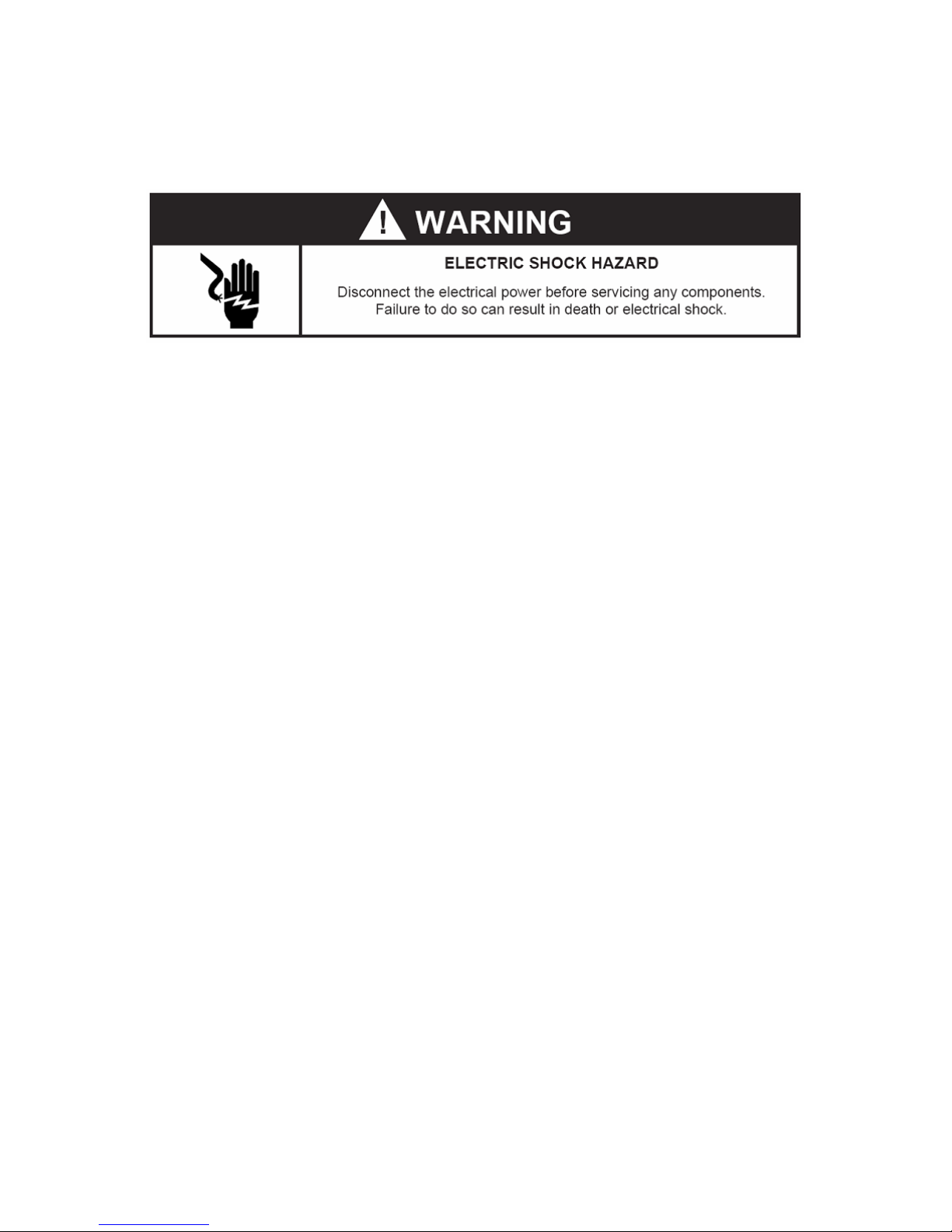
In general, always unplug system or disconnect power while doing care.
1. Coil Cleaning
• Clean the condenser coil regularly. Coil may need to be cleaned at
least every 6 months.
• Unplug the system or disconnect power.
• Use a condenser brush or a vacuum cleaner with an extended
attachment to clean the coil when it is dusty or dirty.
• Plug cooling system or reconnect power.
2. Moisture Removing
• Remove the extra condensate if it is accumulated in the wine cellar at
high ambient temperature and humidity.
- 12 -
Page 14
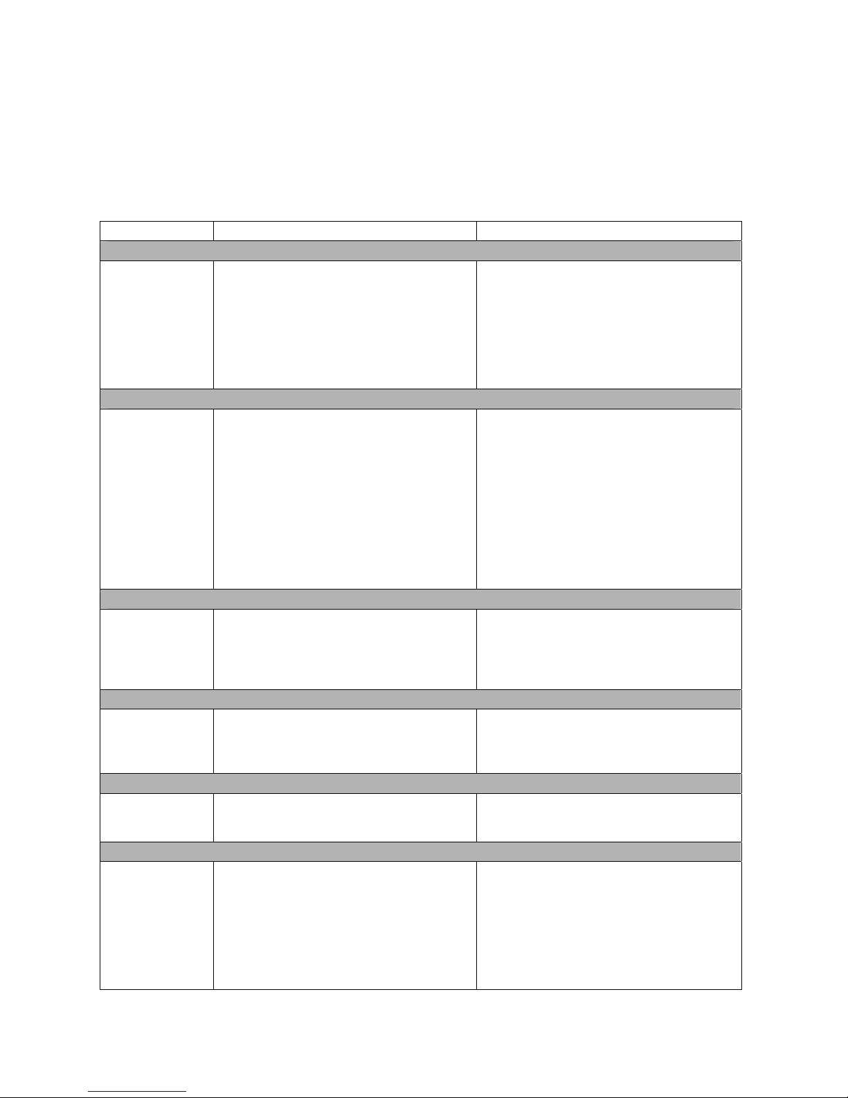
Troubleshooting
This Troubleshooting Chart is not prepared to replace the training required for a
professional refrigeration service person, not is it comprehensive
Troubleshooting Chart
Complaint Possible Causes Response
1. Unit not running
a. Power cord unplugged
b. No power to unit
c. Temperature setting high
d. Low voltage.
e. Incorrect or loose wirings.
f. Defrost light blinking
g. Running light blinking
2. Compressor stopping and starting but short running time
a. Incorrect temperature setting
b. Incorrect voltage
c. Failed thermistor
d. Failed components
e. Improper condenser airflow
f. Dirty condenser
g. Overcharge of refrigerant
h. Discharge or suction pressure too
high
3. Fan motor running but compressor not running
a. Incorrect power supply
b. Incorrect or loose wirings
c. Failed components
d. Liquid refrigerant in the compressor
4. Compressor running but fan not running
a. Fan blade bond
b. Incorrect or loose wirings
c. Failed motors
5. No cooling but compressor and fan running
a. Evaporator airflow restriction
b. Refrigerant leakage
c. Refrigeration system restriction
6. Temperature too high or unit running too long
a. Improper evaporator or condenser
airflow
b. Dirty Condenser
c. Iced evaporator
d. Malfunctioning fans
e. Improper seals
f. Improper area to be cooled.
a. Check for power cord plug
b. Check power at receptacle & fuses
c. Lower temperature setting
d. Contact an authorized electrician
e. Check all wirings and connections
f. Under defrost
g. Call service for failed components
a. Set 55 to 60
b. Check for voltage
c. Check thermistor by placing it in ice
water and measuring resistance
d. Check compressor windings, start
relay and overload protector.
e. Check for condenser fan
f. Clean condenser
g. Call service for removing refrigerant
h. Call service for OEM information
a. Check for proper voltage
b. Check all wirings and connections
c. Check start relay, start capacitor,
overload protector, compressor.
d. Call service for OEM information.
a. Check for proper clearance
b. Check all wirings
c. Call service for checking open or
shorted windings
a. Check for airflow through evaporator
b. Check for loss of refrigerant
c. Call service for checking restrictions
a. Check for air restrictions
b. Clean condenser
c. Defrost and reset temperature
d. Check for both fans
e. Check for gasket and door opening
f. Check for excessive load incorrect
installation
°F
- 13 -
Page 15
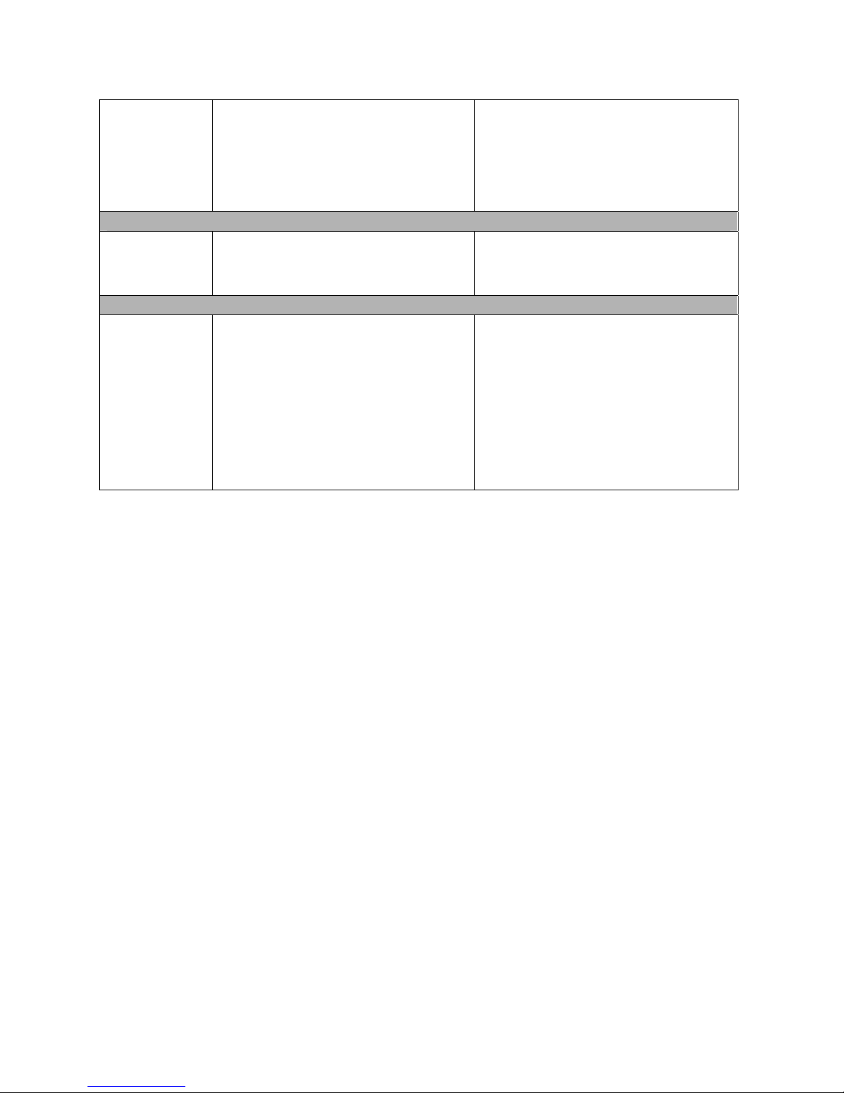
g. Low voltage
h. Operating 60 Hz unit at 50Hz
i. Sealed system problem
j. Undercharge or overcharge
7. House circuit tripping
a. Incorrect fuse or breaker
b. Incorrect wirings
c. Failed components
8. Noisy operation
a. Mounting area not firm
b. Loose parts
c. Compressor overloaded due to high
ambient temperatures or airflow
restriction
d. Malfunctioning components
g. Check power supply
h. Use proper 60 Hz
i. Call service for checking loss of
refrigerant or restrictions
j. Call service to add or remove
refrigerant
a. Check for proper fuse or breaker
b. Check for wirings and connections
c. Call service
a. Add support to improve installation
b. Check fan blades, bearings, cabinet
washers, tubing contact and loose
screws.
c. Check for airflow blockage
d. Call service for checking Internal
loose, inadequate lubrication and
incorrect wirings
- 14 -
Page 16

Customer Support
If you still have problems, please contact us at:
Vinotemp International
17631 South Susana Road
Rancho Dominguez, CA 90221
Tel: (310) 886-3332
Fax: (310) 886-3310
Email: [email protected]
- 15 -
Page 17

Warranty
Thank you for choosing a Vinotemp wine cellar.
Please enter the complete model and serial numbers in the space provided:
Model_________________________________________________________
Serial No.______________________________________________________
Attach your purchase receipt to this owner’s manual.
1. Limited Warranty
VINOTEMP warrants its products, parts only, to be free from defects due to
workmanship or materials under normal use and service for twelve months after
the initial sale. If the product is defective due to workmanship or materials, is
removed within twelve months of the initial sale and is returned to VINOTEMP, in
the original shipping carton, shipping prepaid, VINOTEMP will at its option, repair
or replace the product free of charge.
This warranty constitutes the entire warranty of the VINOTEMP with respect to its
products and is in lieu of all other warranties, express or implied, including any of
fitness for a particular purpose. In no event shall VINOTEMP be responsible for
any consequential damages what is so ever. Any modification of VINOTEMP
products shall void this warranty.
Service under Warranty
This service is provided to customers within the continental UNITED STATES
only. VINOTEMP cooling units are warranted to produce the stated number of
BTU/H. While every effort has been made to provide accurate guidelines,
VINOTEMP can not warranty its units to cool a particular enclosure.
In case of failure, VINOTEMP cooling units must be repaired by the factory or its
authorized agent. Repairs or modifications made by anyone else will void the
warranty.
Should a VINOTEMP cooling unit fail, contact the dealer for instructions. Do not
return the unit to the factory without authorization from VINOTEMP. If the unit
requires repair, re-pack it in the original shipping carton and return it to the
factory, shipping prepaid. VINOTEMP will not accept COD shipments. If the unit
is determined to be faulty and is within the twelve month warranty period
- 16 -
Page 18

VINOTEMP will, at its discretion, repair or replace the unit and return it free of
charge to the original retail customer. If the unit is found to be in good working
order, or beyond the initial twelve month period, it will be returned freight collect.
2. Limitation of Implied Warranty
VINOTEMP’S SOLE LIABILITY FOR ANY DEFECTIVE PRODUCT IS LIMITED
TO, AT OUR OPTION, REPAIRING OR REPLACING OF UNIT.
VINOTEMP SHALL NOT BE LIABLE FOR:
DAMAGE TO OTHER PROPERTY CAUSED BY ANY DEFECTS IN THE UNIT,
DAMAGES BASED UPON INCONVENIENCE, LOSS OF USE OF THE UNIT,
LOSS OF TIME OR COMMERCIAL LOSS, ANY OUTER DAMAGES,
WHETHER INCIDENTAL, CONSEQUENTIAL OR OTHERWISE.
THIS WARRANTY IS EXCLUSIBE AND IS IN LIEU OF ALL OTHER
WARRANTIES, EXPRESSED OR INPLIED, INCLUDING BUT NOT LIMITED
TO, IMPLIED WARRANTIES OF MERCHANTABILITY OR FITNESS FOR A
PARTICULAR PURPOSE.
While great effort has been made to provide accurate guidelines VINOTEMP
cannot warrant its units to properly cool a particular enclosure. Customers are
cautioned that enclosure construction, unit location and many other factors can
affect the operation and performance of the unit. There for suitability of the unit
for a specific enclosure or application must be determined by the customer and
cannot be warranted by VINOTEMP.
- 17 -
 Loading...