

Vinh Quang Dream like Instruction Manual
RADIO CONTROL MODEL
Wing span: 1510mm
Length: 1030mm
Weight (ready to fly): 2.4-2.6Kg
Engine: 2T .46 / 4T .52
or electric equivalent
Radio: 5 channel / 5 servos
INSTRUCTION MANUAL
Dream like
.40 ARF LOW WING TRAINER
WARNING! This radio controlled model is NOT a toy. If modified or flown carelessly it could go out of controll and
cause serious human injury or property damage. Before flying your airplane, ensure the air field is spacious enough.
Always fly it outdoors in safe areas and seek professional advice if you are unexperienced.
ALL WOOD AND ALMOST READY TO FLY

1.5mm
A
B
!
CA
L/R
Assemble left and right
sides the same way.
X
Drill holes using the stated
size of drill
(in this case 1.5 mm Ø)
Use epoxy glue
Take particular care here
Hatched-in areas:
remove covering
film carefully
Not included.
These parts must be
purchased separately
Check during assembly that these
parts move freely, without binding
Apply cyano glue
The pre-covered film on ARF kit may wrinkle due to variations
of temperature. Smooth out as explained right.
* Use an iron or heat gun. Start as low setting. Increase the
setting if necsessary. If it is too high, you may damage the
film
Low setting
SILICON
EPOXY A
EPOXY B
CA
GLUE
Epoxy Glue ( 5 minute type)
Silicon sealer
Cyanoacrylate
Glue
Minimum 5 channel radio
for airplane with 5 servos
.52 - 4 cycle
10.5x6 for .40 - 2 cycle engine
11x6 for .46 - 2 cycle engine
11x7 for .52 - 4 cycle engine
12x7 for .70 - 4 cycle engine
12x7~ 13X6 for Brushless Motor
Silicone tube
Extension for aileron
servo, retract servo.
.40 ~ .46 - 2 cycle
REQUIRED FOR OPERATION (Purchase separately)
Epoxy Glue (30 minute type)
TOLLS REQUIRED
Hobby knife
Needle nose Pliers
Phillip screw driver
Awl
Scissors
Wire Cutters
(Purchase separately)
Hex Wrench
.........................................................
.........................................................
.........................................................
.........................................................
.........................................................
.........................................................
.........................................................
.........................................................
.........................................................
.........................................................
.........................................................
Sander
Masking tape - Straight Edged Ruler - Pen or pencil - Rubbing alcohol - Drill and Assorted Drill Bits
Read through the manual before you begin, so you will have an overall idea of what to do.
Symbols used throughout this instruction manual, comprise:
(Purchase separately)
.Motor control x1 .Aileron x2
.Elevator x1 .Rudder x1
450 - 650 Watt
Brushless Motor
Brushless
Motor Control
Li-Po Battery
CONVERSION TABLE
1.0mm = 3/64”
1.5mm = 1/16”
2.0mm = 5/64”
2.5mm = 3/32”
3.0mm = 1/8”
4.0mm = 5/32”
5.0mm = 13/64”
6.0mm = 15/64”
10mm = 13/32”
12mm = 15/32”
15mm = 19/32”
20mm = 51/64”
25mm = 1”
30mm = 1-3/16”
45mm = 1-51/64”
A
B
! Make sure to glue
securely, If not properly
glued, a failure in flight may
occur.
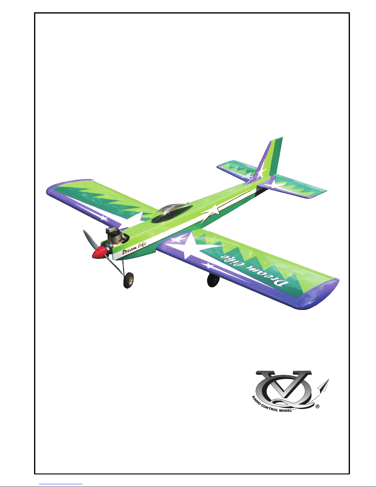
1-Trial fit each part before gluing . Be certain
that there are no gaps. If the parts will join,
but with a gaps, sand or trim the parts a little
at a time until the parts meet exactly with no
gaps.
2-Check for the correct dihedral angle
Carefully slide the wing halves together, ensuring that they are accurately aligned, Firmly press the two
halves together, allowing the excess epoxy run out. Clean off the excess epoxy
3-When joining the wing halves it is extremely important to use plenty of epoxy (30 minutes epoxy).
WING TOP-VIEW
1- Joining the wing
A
B
IMPORTANT:
Please do not clean off the excess epoxy on the wing with strong solvent or pure alcohol, only use
kerosene to keep the colour of your model not fade.
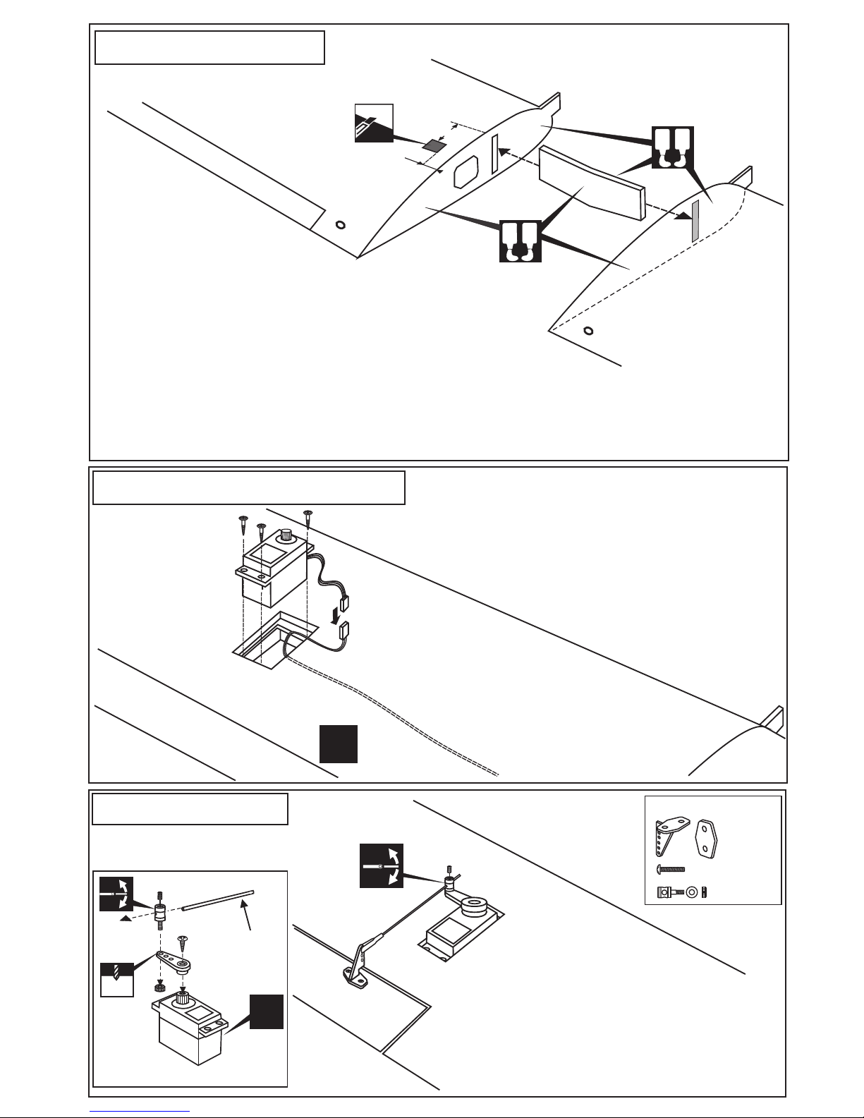
2- Aileron servo installation
Extension cord
Cut away the covering of the wing bottom where the
aileron servo goes.
Install the servo extension cord in to the wing.
Install the aileron servo on the servo mount.
Aileron linkage
AILERON SERVO
WING BOTTOM-VIEW
WING BOTTOM-VIEW
Attach the control horn on the aileron with 2x15mm screws.
Screw the clevies halfway on the theared end of the aileron
push rod. Attach the push rod to the aileron horn. Mark the
position where the push rod will attach to the servo arm.
Cut off the excess length of the push rod
Plastic control horn
..........2
...................4
..........2
Included with the
radio set.
X
X
3mm set Screw
2 mm
Aileron pushrod
D=5/64”(2mm)
Ensure that the servo is centered. If necessary, adjust the
metal clevis so the aileron is also in the neutral position.
20mm
15mm
Cut the hole for the
aileron servo extension.
 Loading...