


Turbine SIP Video Station
180 mm
Mounting Manual
1 Turbine SIP Video Stations
This document specifies the dimensions, mounting procedure, and camera field of view of the Turbine SIP
Video Stations. Zenitel takes no responsibility for damages caused by improper or inadequate mounting.
The Turbine Video series comprises the following stations & accessories:
ITEM NUMBER TYPE ITEM NAME
1008215020 TCIV-2SIP Turbine SIP Video - stainless steel front plate
1008215030 TCIV-3SIP Turbine SIP Video - thermoplastic front plate
1008215060 TCIV-6SIP Turbine SIP Video - thermoplastic front plate with PMOLED display
1008140010 TA-1 Turbine On-Wall Back Box
1008140020 TA-2 Turbine Flush Mount 2-Gang Double-Depth Back Box
1008140050 TA-5 Turbine Bracket for Flush Mount Back Box
TCIV-2SIP TCIV-3SIP TCIV-6SIP
1.1 Station Dimensions
120 mm
96 mm
23.8 mm49 mm
156 mm

2 On-Wall Surface Mounting
150 mm
3”
Mounting Hole
2.1 On-Wall Surface Mount Backbox - TA-1
Mounting Hole
5.90”
4.72”
120 mm
cable holes
M20
M16
6.5 mm
D
0.25”
D
25 mm
1”
Mounting holes are to be drilled
as shown.
Max. recommended screw
diameter: ISO M6 or ANSI 1/4".
Screw length must be greater
than 25 mm or 1".
A4 stainless steel socket head
screws/bolts are recommended.
Max. recommended screw
head diameter: 9.5 mm or 3/8".
Optional washers for extra protection
against corrosive effects between
surfaces are provided.
They should be placed at the bottom
of the 4 mounting holes.
Grommets and an M20 cable gland
are provided.
Mounting Hole
76 mm
2.2 On-Wall Surface Mounting Procedure
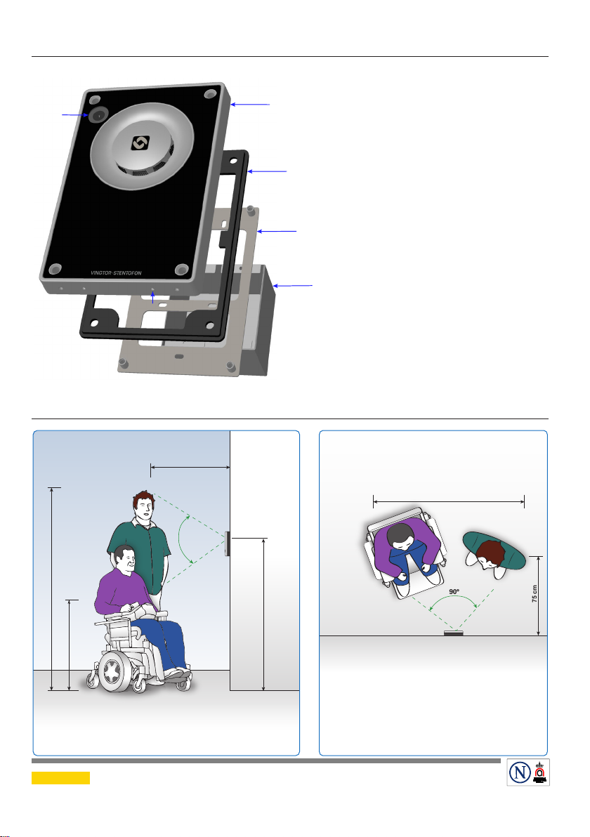
Camera
Lens
Microphone
Washers
1. Mount the backbox onto the wall
2. Fit the gasket onto the backbox with the ridged side facing down
– Plug the Ethernet cable into the RJ-45 port on the station
3. Mount the station onto the backbox with the M5 fasteners provided applying 1.5 Nm
torque
Mounting Hole
3
Turbine
Station
Gasket
2
1
Surface
Mount
Back Box
L The Gasket MUST be mounted to
seal the station!
L Ensure the station is mounted verti-
cally with the microphone aperture
facing down.
L Ensure there is enough clearance
under the station so that the microphone aperture is NOT smothered.
L Place the washers at the bottom of
the 4 mounting holes on the back
box.
L Use the grommets and M20 cable
gland provided for the cable holes
on the back box.

3 Flush Mounting
Use screw recommended by back box manufacurer.
3.1 Flush Mount 2-Gang Double-Depth Backbox - TA-2
1.81?
89 mm / 3.50?
22 mm
0.87?
46 mm
0.98?
25 mm
SIDE
23 mm
0.90?
L It is recommended to utilize backboxes with weep holes at the bottom.
3.2 Flush Mount Bracket - TA-5
L The TA-5 Bracket is mandatory for flush mounting.
4 mm
0.16”
46 mm
1.81”
96 mm / 3.78?
96 mm / 3.78?
SIDE
CUTOUT
1.89?
48 mm
89 mm / 3.50?
2.91”
74 mm
4 mm
0.16”
91 mm
3.58”
3.42”
3.27”
87 mm
83 mm
50 mm
1.97”
Fits US 2-GANG electrical boxes.
Recommended screw diameter: up to M4 (5/32")
3.3 Flush Mounting Procedure
90°
75 cm
192 cm
88 cm
140 cm
70°
L The Gasket MUST be mounted to seal the station!
Camera
Lens
Microphone
4
Turbine
Station
Gasket
4 Camera Field of View
3
2
Bracket
2-Gang
Back Box
L Ensure the station is mounted vertically
with the microphone aperture facing
down.
L Ensure there is enough clearance under
the station so that the microphone
aperture is NOT smothered.
L Apply silicone sealant all around the
aluminum frame of the station, making
sure to leave the microphone aperture
open.
1. Mount the 2-gang back box into the
wall
1
2. Mount the bracket onto the back box
3. Fit the gasket onto the bracket with
the ridged side facing down
– Plug the Ethernet cable into the RJ-45 port
on the station
4. Mount the station onto the bracket
with the M5 fasteners provided
150 cm
DOC NO.
A100K11826
Zenitel and its subsidiaries assume no responsibility for any errors that may appear in this publication, or for damages arising from the information therein. VINGTOR-STENTOFON products are developed and
marketed by Zenitel. The company’s Quality Assurance System is certified to meet the requirements in NS-EN ISO 9001. Zenitel reserves the right to modify designs and alter specifications without notice.
ZENITEL PROPRIETARY. This document and its supplementing elements, contain Zenitel or third party information which is proprietary and confidential. Any disclosure, copying, distribution or use is
prohibited, if not otherwise explicitly agreed in writing with Zenitel. Any authorized reproduction, in part or in whole, must include this legend. Zenitel – All rights reserved.
Vertical Angle
29.8.2018
Horizontal Angle
customer.service@zenitel.com
75 cm
 Loading...