


TECHNICAL MANUAL A100K11194
Configuration Guide
Turbine Compact IP Stations

About this Document
Document Scope
This document describes the setup procedure and conguration of the various
models of the Turbine Compact IP station series.
Station Software Version: 3.0.3.3 or later
Product Item Number
Tubine Compact IP Station - TCIS-1 1008111010
Tubine Compact IP Station - TCIS-1-V 1028111010
Tubine Compact IP Station - TCIS-2 1008111020
Tubine Compact IP Station - TCIS-3 1008111030
Tubine Compact IP Station - TCIS-4 1008111040
Tubine Compact IP Station - TCIS-5 1008111050
Tubine Compact IP Station - TCIS-6 1008111060
Turbine Kit - VoIP Intercom Module - TKIS-2 1008131020
Surface Mount Back Box - TA-1 1008140010
Flush Mount 2-Gang Double-Depth Back Box - TA-2 1008140020
Flush Mount Bracket - TA-5 1008140050
Publication Log
Rev. Date Author Status
1.0 21.9.2012 HKL Published
1.1 13.12.2012 HKL TKIS-2
1.2 16.1.2013 HKL I/Os, conversation mode
1.3 1.8.2013 HKL Electret mic setting
Related Documentation
For further information, refer to the following documentation:
Doc. number Documentation
A100K11254 Turbine Compact IP Stations Mounting Guide
A100K11258 Turbine Compact Analog Stations Mounting Guide
A100K10805 AlphaCom XE Installation & Conguration

3
Turbine Station Conguration Guide
A100K11194
Contents
1 Turbine Compact IP Stations ........................................................................................................ 5
2 Station Connections ...................................................................................................................... 7
2.1 External Connectors on IP Station .......................................................................................... 7
2.2 Power Supply .......................................................................................................................... 7
2.3 Network Connection ................................................................................................................ 7
2.4 Input/Output Connections ....................................................................................................... 7
3 Starting Up the Station .................................................................................................................. 8
4 AlphaComConguration .............................................................................................................. 9
4.1 Logging into the Station .......................................................................................................... 9
4.2 Station Main Settings ........................................................................................................... 10
4.3 Advanced AlphaCom Settings................................................................................................11
4.4 Audio Settings .......................................................................................................................11
4.5 I/O Settings ........................................................................................................................... 13
4.6 OLED Labels ......................................................................................................................... 13
4.7 Address Book ........................................................................................................................ 14
4.8 Sound Detection.................................................................................................................... 14
5 SIPConguration......................................................................................................................... 15
5.1 Logging into the Station ........................................................................................................ 15
5.2 Station Main Settings ........................................................................................................... 16
5.3 SIP Settings .......................................................................................................................... 17
5.4 Audio Settings ....................................................................................................................... 19
5.5 Direct Access Key Settings ................................................................................................... 21
5.6 Relay Settings ....................................................................................................................... 22
5.7 SNMP Settings ...................................................................................................................... 23
5.8 Automatic Conguration using TFTP .................................................................................. 26
6 PulseConguration ..................................................................................................................... 27
6.1 Logging into the Station ........................................................................................................ 27
6.2 Station Main Settings ........................................................................................................... 28
6.3 Connect other Intercom Stations........................................................................................... 29
6.4 Congure Directory (Phonebook).......................................................................................... 29
6.5 Verify System Setup .............................................................................................................. 29
6.6 Congure Call and Audio Settings ........................................................................................ 30
6.7 Congure the Call Buttons on an IP Substation .................................................................... 30
6.8 Add SIP Accounts for 3
rd
-party IP Telephone and IP DECT .................................................. 31
6.8.1 Create SIP station account ......................................................................................... 31
6.8.2 Congure IP telephone ............................................................................................... 32
6.9 Add SIP Accounts for Telephone Gateways .......................................................................... 32
6.9.1 Install license ............................................................................................................... 32
6.9.2 Create SIP gateway account ....................................................................................... 32
6.9.3 Congure telephone gateway ..................................................................................... 32
6.10 Modify Pulse Station Proles ................................................................................................ 33
7 Common Advanced Network Settings ....................................................................................... 34
8 Station Software Upgrade ........................................................................................................... 35
8.1 Prerequisites ......................................................................................................................... 35
8.2 Upgrade Via Station Web Interface ....................................................................................... 35
8.3 Upgrade Via AlphaCom XE ................................................................................................... 36
9 Station Indication LEDs .............................................................................................................. 37
9.1 LEDs on Front Plate .............................................................................................................. 37
9.2 Status LEDs on PCB ............................................................................................................. 37
9.3 Ethernet Activity & Speed LEDs on PCB .............................................................................. 37
10 Restoring Factory Defaults ......................................................................................................... 38
10.1 Reset to Factory Default Settings with Activated DHCP ....................................................... 38
10.2 Reset to Factory Default Settings with Static IP .................................................................... 38
11 Compact Station & Accessories Dimensions ........................................................................... 39
11.1 Compact Station Dimensions ................................................................................................ 39
11.2 On-Wall Surface Mount Back Box - TA-1 .............................................................................. 39
11.3 Flush Mount Bracket - TA-5 .................................................................................................. 40
11.4 Turbine Kit VoIP Intercom Module - TKIS-2 .......................................................................... 40
12 TurbineStationSpecications ................................................................................................... 41

4
A100K11194
Turbine Station Conguration Guide
A: CongurationFileParametersforSIPProvisioning ................................................................ 43
A.1 Remote Provisioning using TFTP ........................................................................................ 43
A.2 General Parameters ............................................................................................................. 43
A.3 SIP Parameters .................................................................................................................... 44
A.4 Call Parameters ................................................................................................................... 45
A.5 Relay Parameters ................................................................................................................ 48
A.6 SNMP Parameters ............................................................................................................... 49
A.7 Example Conguration File ................................................................................................... 52
B: Station Board Connections & Indicators ................................................................................... 54
B.1 PCB - Front ........................................................................................................................... 54
B.2 Input Connectors ................................................................................................................... 55
B.3 Output Connectors + 1 relay ................................................................................................. 55
B.4 PCB - Rear ............................................................................................................................ 56
B.5 Front Board - Front ................................................................................................................ 57
B.6 Front Board - Rear ................................................................................................................ 57
Figures
Figure 1 Turbine TCIS-1 Station Keys & Functions ............................................................................ 6
Figure 2 Turbine TCIS-6 Station Keys & Functions ............................................................................ 6
Figure 3 External Connectors on IP Station ........................................................................................ 7
Figure 4 AlphaCom Intercom System ................................................................................................. 9
Figure 5 SIP System ......................................................................................................................... 15
Figure 6 Pulse System ...................................................................................................................... 27

5
Turbine Station Conguration Guide
A100K11194
1 Turbine Compact IP Stations
All IP stations in the Turbine series utilize the latest technology to produce
unparalleled audio quality. Some of the many features include: HD voice
quality, Open Duplex, Active Noise Cancellation, MEMS microphone, a
10W Class D amplier and our unique speaker grille design.
There are six station models in the Turbine Compact series:
TCIS-1/TCIS-1-V
Thermoplastic frontplate with single call
button plus Push-To-Talk & Cancel
TCIS-2
Stainless steel frontplate with single call button
TCIS-3
Thermoplastic frontplate with single call
button
TCIS-4
Thermoplastic frontplate with single call button
and PMOLED display
TCIS-5
Thermoplastic frontplate with two call buttons
and PMOLED display
TCIS-6
Thermoplastic frontplate with call & scrolling
buttons and PMOLED display
TKIS-2
The encapsulated TKIS-2 Turbine Kit VoIP Intercom Module can
be used to build customized intercom or help point solutions.
VoIP and CCoIP can be added to parking solutions, cash points,
vending machines, et al.

6
A100K11194
Turbine Station Conguration Guide
Figure 1 Turbine TCIS-1 Station Keys & Functions
Figure 2 Turbine TCIS-6 Station Keys & Functions
Loudspeaker
Cancel
Microphone
Manual Speech
Direction Control
Call Button
Loudspeaker
Cancel
Microphone
Call Button
Scroll Up
Scroll Down
PMOLED
Display

7
Turbine Station Conguration Guide
A100K11194
2 Station Connections
2.1 External Connectors on IP Station
Figure 3 External Connectors on IP Station
The following table is an overview of the main connectors involved when
installing the Turbine IP Stations.
Ethernet / Power 10/100 Mbps Ethernet RJ-45 port for LAN (uplink) connection. Supports PoE
(802.3af). Draws power from either spare line or signal line.
Secondary Power 24 VDC (16 – 48 V) secondary power is provided from an external adapter.
Relays There is one Double Throw relay contact with 60W switching power. COM, NO,
NC contacts are provided. Max: 250VAC/220VDC, 2A, 60W.
Input/Output 6 general purpose I/Os are available. Each I/O can be congured as either
button input or LED driver.
Audio Line Out A balanced 600 ohm audio line out with induction loop signal
2.2 Power Supply
The Turbine Station supports Power over Ethernet (PoE, IEEE 802.3 a-f)
where power can be drawn from either the spare line or signal line.
If PoE is not available, the Turbine Station can be connected to a 24 VDC
local power supply.
2.3 Network Connection
There is one RJ-45 port located on the Turbine station that is used as the
PoE/LAN port.
PoE port
2.4 Input/Output Connections
There are 6 I/O connection options for the Turbine Station.
These connections are used as relay contacts for door lock control and
external I/O devices.
1
5
4
3
2
1
6
10
5
4
3
2
9
8
7
RJ-45
PoE
port
24 VDC for external secondary power
if PoE is not used. Pin 1 is positive.
- 5.3V (LED driver)
- GND
- Input/Output 5
- COM relay
- NC relay
- NO relay
- Input/Output 1
- Input/Output 2
- Input/Output 3
- Input/Output 6
- 600 ohm balanced line out +
- 600 ohm balanced line out -
- Input/Output 4
Ethernet Connection

8
A100K11194
Turbine Station Conguration Guide
3 Starting Up the Station
The Turbine Station features an embedded web interface, which allows
users to log in via a standard web browser.
To start up the station, your PC and the IP station have to be connected
together via a PoE switch using network cables:
1. Connect the PC to the PoE switch
2. Connect the PoE port on the IP station to the PoE switch
When the Turbine Station is connected to the network, the IP address of
the station is automatically obtained in one of two ways:
1. An IP address is obtained from a DHCP server if there is one.
2. If there is no DHCP server, an IP address in the range 169.254.x.x
will be assigned.
To make the station speak its IP address:
● Press the call button on the station
- when the station is not registered yet
At commissioning, the IP station needs to be congured to enable it to be
used as:
● station subscribed to an AlphaCom server
● SIP station
● Pulse station
PoE port
IP Network
AlphaCom XE Server/Exchange
Control Room
Master Station
AlphaCom XE7
Turbine TCIS-1
Turbine TICS-5
iPBX (SIP domain)
SIP phone

9
Turbine Station Conguration Guide
A100K11194
4 AlphaComConguration
The Turbine Stations are connected to the AlphaCom XE server/
exchange which is the heart of the STENTOFON security and
communication system. The communication between the AlphaCom XE
exchange and the Turbine Stations utilize the STENTOFON CCoIP®
protocols. The AlphaCom XE server/exchange includes all main service
congurations for the IP stations and only a minimum conguration is
needed to be carried out on the actual station.
Figure 4 AlphaCom Intercom System
4.1 Logging into the Station
Access the station by logging into the web interface using a standard web
browser:
1. Open a web browser
2. In the browser’s address bar, type the station IP address and press
the ENTER key
- The station login page will be displayed.
To log into the station:
1. Click Login
2. Enter the default User name: admin
3. Enter the default password: alphaadmin
The Station Information page will now be displayed, showing the IP
station conguration and status.
IP Network
AlphaCom XE Server/Exchange
IP Desk Master
Control Room
Master Station
AlphaCom XE7
Turbine TICS-6
Turbine TCIS-1
Turbine TICS-5
10
A100K11194
Turbine Station Conguration Guide
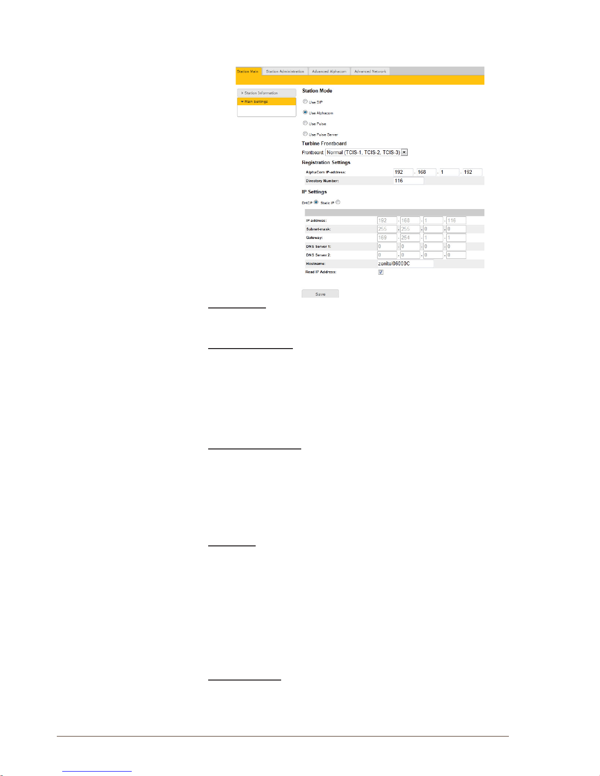
4.2 Station Main Settings
● Click Station Main > Main Settings to access the page for
conguring station mode and IP parameters.
Station Mode
● Select the Use Alphacom radio-button
Turbine Frontboard
Depending on the type of Turbine Compact station, select one of the
options from the drop-down box:
- Kit
- Normal (TCIS-1, TCIS-2, TCIS-3)
- OLED Labels (TCIS-4, TCIS-5)
- Scrolling Station (TCIS-6)
Registration Settings
● Enter the IP address of the AlphaCom server/exchange in which the
IP station is to be a subscriber in the AlphaCom IP-address eld.
● Enter the directory no. of the station in the Directory Number eld.
- If a directory number is not entered, the station will register with
its MAC address. The MAC address is found on the Station
Information page and needs to be entered into AlphaPro.
IP Settings
● DHCP – Select this option if the IP station shall receive IP Settings
from a DHCP server.
● Static IP – Select this option if the IP station shall use a static IP
address. Enter values for:
- IP-address
- Subnet-mask
- Gateway
- DNS Server 1 (option for network administration)
- DNS Server 2 (option for network administration)
- Hostname (option for network administration)
Read IP Address
● Check the Read IP Address box to enable an unregistered station to
speak the IP address when the call button is pressed.
Click Save followed by Apply to apply the new conguration settings.

11
Turbine Station Conguration Guide
A100K11194
4.3 Advanced AlphaCom Settings
● Select Advanced AlphaCom to access the page for conguring
parameters for audio, I/O settings, OLED labels, address book,
sound detection.
4.4 Audio Settings
To congure audio settings:
● Select Advanced Alphacom > Audio from the menu
● Select or set values for the parameters:
- Microphone Sensitivity
- Automatic Volume Control
- Debug Automatic Volume Control
- Conversation Mode
- Audio prole
- Line Out Source
Microphone Sensitivity
- Select the sensitivity level in the range 0 to 7 from the drop-down
box. The default setting is 5.
Automatic Volume Control
- Check the box to enable automatic volume control that is adjusted
according to the noise level
Debug Automatic Volume Control
- Check the box to show current volume level on OLED display
Conversation Mode
For this parameter, there are ve options:
- Full Open Duplex: Normal mode with echo cancellation
- Robust Duplex: Option used when open duplex fails due to
excessive speaker loudness, microphone overload or very high
nonlinear distortions.
- Half Duplex Switching: Switches speech direction depending on
who speaks the loudest
- Push-To-Talk: Half-duplex communication. Initially the microphone
is shut off. Push the M-button to open the microphone, and release
to listen. (Only applicable to TCIS-1 station)
- Open: Full Open Duplex without echo cancellation

12
A100K11194
Turbine Station Conguration Guide
Line Out Source
This parameter can play audio either from VoIP signal (Speaker) or direct
from Microphone.
AudioProle
For this parameter, there are 2 options: Normal or Advanced.
● Select Advanced to access additional and detailed menu options for
audio settings such as noise and echo cancellation:
Advanced Audio Settings
L These parameters are optional.
The functions and default values for each parameter are described under
Advanced Audio Settings.

13
Turbine Station Conguration Guide
A100K11194
4.5 I/O Settings
● Select Advanced AlphaCom > I/O Settings from the menu
● Select either Input or Output options from the drop-down box for I/O
Pins 1 to 6.
4.6 OLED Labels
L Note that only Turbine stations congured with OLED Labels (TCIS-4, TCIS-5)
under Main Settings will have this menu option.
● Select Advanced AlphaCom > OLED Labels from the menu
OLED Display Text
● Enter display text in the relevant elds for OLED 1 and OLED 2.
OLED Font Size
● The font size can be either 12 or 16
OLED Brightness
● Brightness: Default, Bright, Extra Bright

14
A100K11194
Turbine Station Conguration Guide
4.7 Address Book
L Note that only the Turbine station congured as a Scrolling Station (TCIS-6)
under Main Settings will have this menu option.
● Select Advanced AlphaCom > Address Book from the menu
Default Display Text
● The idle text shown in the display may be changed. The default text
is: Scroll to Select
Font Size
● The font size can be either 12 or 16
OLED Brightness
● Brightness: Default, Bright, Extra Bright
Start Scrolling After
● Set the time in minutes after which scrolling should start
Upload Address Book
A CSV le consisting of directory numbers and display text with the semicolon character (;) as delimiter may be uploaded.
● Click Browse to upload a CSV le
4.8 Sound Detection
● Select Advanced Alphacom > Sound Detection from the menu
Sound Detection Settings
Here you can set the minimum amplitude and duration of the audio, the
DAK to activate, etc.

15
Turbine Station Conguration Guide
A100K11194
5 SIPConguration
SIP (Session Initiation Protocol) is the de facto standard for IP telephony.
The STENTOFON SIP intercom stations are specially built for easy
integration with any iPBX system.
The STENTOFON SIP Stations are custom-made IP intercom stations
that can integrate with any iPBX system.
IP Network
SIP phone
iPBX (SIP domain)
SIP phone
Turbine TCIS-1
Turbine TICS-5
Turbine TICS-6
Figure 5 SIP System
5.1 Logging into the Station
Access the station by logging into the web interface using a standard web
browser:
1. Open a web browser
2. In the browser’s address bar, type the station IP address and press
the ENTER key
- The station login page will be displayed.
To log into the station:
1. Click Login
2. Enter the default User name: admin
3. Enter the default password: alphaadmin
The Station Information page will now be displayed, showing the station
settings and status.

16
A100K11194
Turbine Station Conguration Guide
5.2 Station Main Settings
● Click Station Main > Main Settings to access the page for
conguring station mode and IP parameters.
Station Mode
● Select the Use SIP radio-button
Turbine Frontboard
Depending on the type of Turbine Compact station, select one of the
options from the drop-down box:
- Kit
- Normal (TCIS-1, TCIS-2, TCIS-3)
- OLED Labels (TCIS-4, TCIS-5)
- Scrolling Station (TCIS-6)
IP Settings
● DHCP – Select this option if the IP station shall receive IP Settings
from a DHCP server.
● Static IP – Select this option if the IP station shall use a static IP
address. Enter values for:
- IP-address
- Subnet-mask
- Gateway
- DNS Server 1 (option for network administration)
- DNS Server 2 (option for network administration)
- Hostname (option for network administration)
Read IP Address
● Check the Read IP Address box to enable an unregistered station to
speak the IP address when the call button is pressed.
● Click Save followed by Apply to apply the new conguration
settings.

17
Turbine Station Conguration Guide
A100K11194
5.3 SIP Settings
● Select SIPConguration > SIP Settings to access the page for
conguring SIP parameters.
Account Settings
Display Name
- Enter a name that will be shown on the display at the remote party.
Directory Number (SIP ID)
- This is the identication of the station in the SIP domain, i.e. the
phone number for the station. This parameter is mandatory. Enter
the SIP ID in integers according to the SIP account on the SIP
domain server.
Server Domain (SIP)
- This parameter is mandatory and species the primary domain for
the station and is the IP address for the SIP server (e.g. Asterisk or
Cisco Call Manager). Enter the IP address in regular dot notation,
e.g. 10.5.2.138.
Backup Domain (SIP)
- This is the secondary (or fallback) domain. If the station loses
connection to the primary SIP domain, it will switch over to the
secondary one. Enter the IP address in regular dot notation.
Backup Domain 2 (SIP)
- This is the tertiary backup domain.
Authentication User Name
- This is the authentication user name used to register the station
to the SIP server. This is required only if the SIP server requires
authentication and is normally the same as the SIP ID.

18
A100K11194
Turbine Station Conguration Guide
Authentication Password
- The authentication user password used to register the station
to the SIP server. This is required only if the SIP server requires
authentication
Register interval
- This parameter species how often the station will register, and
reregister in the SIP domain. This parameter will affect the time it
takes to detect that a connection to a SIP domain is lost.
- Enter the values in number of seconds from 60 to 999999. The
default interval is 600 seconds.
Outbound Proxy [optional]
- Enter the IP address of the outbound proxy server in regular dot
notation, e.g. 10.5.2.100
Port
- Enter the port number used for SIP on the outbound proxy server.
The default port number is 5060.
Call Settings
Enable Auto Answer
- This is not required. Enables automatic answer after a set number
of seconds.
- Check the box to enable this function and enter the delay in
seconds in the eld for Auto Answer Delay. The default delay
setting is 0 and the maximum is 30 seconds.
Delay Call Setup
- This only applies to input buttons and DAKs. The default delay
setting is 0 and the maximum is 60 seconds.
Overlap dialing
- This will lead to the phone starting to dial each time a digit is
entered and the SIP proxy replying with ‘Number incomplete’ until
such time as the number has been entered and the call can be
initiated successfully without the enter key having to be pressed.
DTMF method
- Choose between SIP INFO or RFC 2833 to select DTMF signalling
method.
RTP Timeout value
- This cancels a call if the station does not receive RTP packets from
the remote party. Enter values in the range 0-9999 seconds. The
default setting is 0 which means RTP timeout is disabled.
After entering all the desired values, click Save and then click Reboot to
enable the SIP settings.

19
Turbine Station Conguration Guide
A100K11194
5.4 Audio Settings
Select SIPConguration > Audio Settings
Speaker Volume
- Select the volume level in the range 0 to 7 from the drop-down
menu.
- Default setting is 5
Noise Reduction Level
- The higher the noise reduction level the more deterioration there is
in audio quality.
- Default setting is 0 (i.e. the function is disabled)
Microphone Sensitivity
- Select the sensitivity level in the range 0 to 7 from the drop-down
menu.
- Default setting is 5
Remote Controlled Volume Override Mode
- This acts as simplex mode. This feature is activated after the rst
DTMF * or # is received from the remote station. Send DTMF * to
talk and # to listen.
- Check the box to enable this function.
- Default setting is an unchecked box (i.e. the function is disabled)
Message Controlled Volume Override Mode
Check the box to enable the following messages:
- SIP MESSAGE “Audio_receive_only”: Turns the microphone off
and loudspeaker on
- SIP MESSAGE “Audio_send_only”: Turns microphone on and
loudspeaker off
- SIP MESSAGE “Audio_send_receive”: Turns both microphone and
loudspeaker on
- Default setting is an unchecked box (i.e. the function is disabled)
Automatic Volume Control
- Check the box to enable automatic volume control that is adjusted
according to the noise level
- Default setting is an unchecked box (i.e. the function is disabled)
Debug Automatic Volume Control
- Check the box to show current volume level on OLED display
- Default setting is an unchecked box (i.e. the function is disabled)

20
A100K11194
Turbine Station Conguration Guide
Conversation Mode
- Full Open Duplex: Normal mode with echo cancellation
- Robust Duplex: Option used when open duplex fails due to
excessive speaker loudness, microphone overload or very high
nonlinear distortions.
- Half Duplex Switching: Switches speech direction depending on
who speaks the loudest
- Push-To-Talk: Half-duplex communication. Initially the microphone
is shut off. Push the M-button to open the microphone, and release
to listen. (Only applicable to TCIS-1 station)
- Open: Full Open Duplex without echo cancellation
AudioProle
For this parameter, there are 2 options:
- Normal
- Advanced
● Select Advanced to access additional and detailed menu options for
audio settings such as noise and echo cancellation:
Advanced Audio Settings
L These parameters are optional.
The functions and default values for each parameter are described under
Advanced Audio Settings.
● After entering all the desired values, click Save to enable the audio
settings.

21
Turbine Station Conguration Guide
A100K11194
5.5 Direct Access Key Settings
● Select SIPConguration > Direct Access Key Settings to access
the page for conguring DAKs.
Direct Access Key Settings
Direct Access Key 1 - Direct Access Key 2
Enter the number to call in the Value eld.
L Note that the availability of this parameter depends on the Turbine station type
selected such as OLED Labels, Normal, Scrolling Station under Main Settings.
For example, the display above is for OLED Labels (TCIS-4, TCIS-5).
Input Button 1
This is the SIP ID for the extension to be called when call button no. 1 is
pressed, i.e. the SIP ID number of the receiving party.

22
A100K11194
Turbine Station Conguration Guide
Input Button 2
This is the SIP ID for the extension to be called when call button no. 2 is
pressed, i.e. the SIP ID number of the receiving party.
Input Button 3
This is the SIP ID for the extension to be called when call button no. 3 is
pressed, i.e. the SIP ID number of the receiving party.
Direct Access Key Settings (In Call)
- Select input buttons 1 - 6 for direct access calls while in
conversation.
- Options are: End Call, Do Nothing, Send Text, Send DTMF
Ringlist Settings
Enter the values in the elds for Value 1 to Value 9 for Ringlist 1, 2, 3.
5.6 Relay Settings
● Select SIPConguration > Relay Settings to access the page for
conguring relays.
Relay Settings
● Select Relay 1, Ouput 1, Ouput 2, or Ouput 3 from the drop-down
box
Timed Relay Duration
This parameter determines how long the relay should stay ON in
seconds.

23
Turbine Station Conguration Guide
A100K11194
5.7 SNMP Settings
SNMP (Simple Network Management Protocol) is a protocol for
centralizing the management of devices in IP networks.
● Select Advanced Network > SNMP to access the page for
conguring SNMP parameters.
SNMP Settings
Enable SNMP v1
- This enables reading of the MIB using SNMP version 1.
Enable SNMP v2c
- This enables reading of the MIB using SNMP version 2c.
Community string
- Enter a text string used as a password for authentication.
Allowed Network
- This is used, together with the network mask, to determine the
allowed network for reading the MIB on the station.
- The IP address is entered in regular dot notation, e.g. 10.5.2.100.
For example with an allowed network 10.5.2.0 and a network
mask of 24, any station with an IP address in the range 10.5.2.0 to
10.5.2.255 can access the MIB.

24
A100K11194
Turbine Station Conguration Guide
SNMP Trap Settings
Trap receiver
- Enter the IP address of the server receiving SNMP traps. This is
disabled if the eld is left empty.
Enable SNMP Traps
IP-Station Started
- If enabled, the station will send an SNMP trap when the station
application is started.
Registration Successful
- If enabled, the station will send an SNMP trap when successfully
registered in the SIP domain.
Registration Failed
- If enabled, the station will send an SNMP trap if registration in the
SIP domain failed.
Call Connected
- If enabled, the station will send an SNMP trap when a call is
connected.
Call Connect Failed
- If enabled, the station will send an SNMP trap if a call to the station
fails to connect for any reason (busy etc.).
Call Disconnect
- If enabled, the station will send an SNMP trap when a call is
disconnected.
Button Hanging
- If enabled, the station will send an SNMP trap when a button is
hanging.
Sound Test Failed
- If enabled, the station will send an SNMP trap when a sound test
has failed.
Sound Test Error
- If enabled, the station will send an SNMP trap when there is a
sound test error.
Sound Test Success
- If enabled, the station will send an SNMP trap when a sound test is
successful.
Input Button Pressed
- If enabled, the station will send an SNMP trap when an input is
activated.

25
Turbine Station Conguration Guide
A100K11194
Input Button Released
- If enabled, the station will send an SNMP trap when an input is
deactivated.
Dak Pressed
- If enabled, the station will send an SNMP trap when a DAK is
pressed.
Dak Released
- If enabled, the station will send an SNMP trap when a DAK is
released.
Relay Activated
- If enabled, the station will send an SNMP trap when a relay is
activated.
Relay Deactivated
- If enabled, the station will send an SNMP trap when a relay is
deactivated.

26
A100K11194
Turbine Station Conguration Guide
5.8 AutomaticCongurationusingTFTP
A SIP station may be set up to automatically poll conguration settings
for SIP, Call and SNMP from a TFTP server. The IP address of this
TFTP server can be obtained using DHCP procedures or be manually
congured.
Before you start the automatic conguration procedure:
● Create a conguration le.
- The relevant parameters for SIP, Call and SNMP in the
conguration le are described in Appendix A: Conguration File
Parameters for SIP Provisioning.
To carry out automatic conguration from the station web server:
1. Start the TFTP server program and set the server path by browsing
to the directory where the conguration le is located.
2. Log on to the SIP station web server.
3. Select Advanced SIP > Updates
4. Under CongurationUpdates select the radio-button for Automatic
5. Either select the radio-button for From DHCP or enter the IP address
of the TFTP server (your PC IP address)
6. Under Automatic Update Interval enter the interval in minutes for
checking updates.
- The value must be between 1 and 999 and the default setting is 60.
7. Click Savecongurationfor“Updates”
The station will now contact the TFTP server and run the conguration le
to carry out the conguration procedure according to the set time interval.

27
Turbine Station Conguration Guide
A100K11194
6 PulseConguration
STENTOFON Pulse is an IP-based intercom system for upto 16 intercom
stations. The system works with all STENTOFON IP intercom stations.
PoE Network Switch
Turbine IP Station
Directory Number: 12
Name: Rear Entrance
IP Address: 169.254.1.103
or DHCP
Turbine IP
or DHCP
Station
Directory Number: 11
Name: Main Entrance
IP Address: 169.254.1.102
Turbine IP Station - Pulse Server
Directory Number: 10
Name: Reception Desk
IP Address: 169.254.1.99
Figure 6 Pulse System
6.1 Logging into the Station
The Turbine Station features an embedded web server, which allows
users to log in via a standard web browser.
Access the station by logging into the web interface using a standard web
browser:
1. Open a web browser
2. In the browser’s address bar, type the station IP address and press
the ENTER key
- The station login page will be displayed.
To log into the station:
1. Click Login
2. Enter the default User name: admin
3. Enter the default password: alphaadmin
The Station Information page will now be displayed, showing the station
settings and status.
PoE port

28
A100K11194
Turbine Station Conguration Guide
6.2 Station Main Settings
● Click Station Main > Main Settings to access the page for
conguring station mode and IP parameters.
Station Mode
● Select the Use Pulse or Use Pulse Server radio-button
L Use Pulse Server must be selected to be able to carry out the congurations
described in the following sections.
Turbine Frontboard
Depending on the type of Turbine station, select one of the options from
the drop-down box:
- Kit
- Normal (TCIS-1, TCIS-2, TCIS-3)
- OLED Labels (TCIS-4, TCIS-5)
- Scrolling Station (TCIS-6)
IP Settings
● DHCP – Select this option if the IP station shall receive IP Settings
from a DHCP server.
● Static IP – Select this option if the IP station shall use a static IP
address. Enter values for:
- IP-address
- Subnet-mask
- Gateway
- DNS Server 1 (option for network administration)
- DNS Server 2 (option for network administration)
- Hostname (option for network administration)
Read IP Address
● Check the Read IP Address box to enable an unregistered station to
speak the IP address when the call button is pressed.
● Click Save followed by Apply to apply the new conguration
settings.

29
Turbine Station Conguration Guide
A100K11194
6.3 Connect other Intercom Stations
Connect all other IP intercom stations to the network. Note that all other
IP intercom stations have to be on the same LAN (IP subnet) as the
Pulse Server.
Wait for the stations to boot up (approximately 60 seconds) before
proceeding to the next step.
6.4 CongureDirectory(Phonebook)
Log into the Pulse Server station with the new IP address (e.g.
169.254.1.99) that you have just set under Station Main > Main
Settings. After login, you will nd a new Server Management tab
● Under the Server Management tab, select ServerConguration>
Directory Settings
The Pulse Server station will auto-discover all the other stations on
the LAN.
To identify the individual stations on the LAN:
● Click Play
- You should now hear a tone from the station you selected.
You can now set directory numbers, names, IP addresses, proles,
etc. for all the stations in the network. In our example, the Pulse Server
station is designated as Reception Desk with directory number 10 while
the two substations are the Main Entrance and Rear Entrance with
directory numbers 11 and 12 respectively.
● Click Save followed by Apply
- When you click Apply, the Pulse Server will download the directory
settings to all the STENTOFON IP intercom stations and do a
system reboot.
L Password is an optional eld you can set to increase the security level. The
password is used by other intercom stations to register with the Pulse Server.
6.5 Verify System Setup
To verify that your system is up and running:
Select Server Management > Server Monitoring
All stations that have been congured should be displayed in the table.
Stations that are up and running will have the status Registered.

30
A100K11194
Turbine Station Conguration Guide
6.6 CongureCallandAudioSettings
It is optional to congure the call and audio settings. Default settings will
be used if they are not congured.
● Select Server Management >ServerConguration> Call and
Audio Settings
The Call and Audio Settings menu include the following parameters:
Autoanswer
Auto-answer is typically enabled for substations and not for master
stations.
Disconnect By Button
When disabled, the user cannot disconnect the call from this station. It is
typically disabled on substations and enabled on master stations.
Activate Relay On Event
Most STENTOFON IP stations have a relay. Here, you can select the
events that activate the relay. The available events are:
● DTMF <#> - Reception of a DTMF (keypad) digit from a remote
station during the call
● Ringing
● In call
Relay duration
When the relay is activated, this parameter determines how long the relay
should stay ON.
Speaker Volume
This parameter sets the speaker volume for the station.
Noise Reduction
This parameter enables active noise cancellation. For stations that
are located in noisy environments, it is recommended that the noise
cancellation level be set to 4.
6.7 ConguretheCallButtonsonanIPSubstation
The IP Substation has three inputs. By default input 1 (Key 1) is
connected to the call button, while the other two inputs (Key 2 and Key 3)
are free and can be used for additional call buttons.
The call buttons of the IP Substations can be congured via the Pulse
Server.
● Use a web browser and log into the Pulse Server station (e.g.
169.254.1.99)
● Select Server Management > ServerConguration> Direct
Access Key Settings

31
Turbine Station Conguration Guide
A100K11194
● Select the station on which you want to program the Call Button
- The Call Button is Input Button 1
● Under Value enter the directory number to call when the button is
pressed.
If you want to use also input 2 (Key 2) and input 3 (Key 3), simply enter
the required value for Input Button 2 and Input Button 3.
6.8 Add SIP Accounts for 3rd-party IP Telephone and
IP DECT
Install license
Before adding SIP accounts to your system, you need to obtain the Pulse
3rd Party SIP Terminals license key.
To install a license:
● Under the Station Administration tab, select Licensing
● Enter the license key in the New License eld and click Insert
License
The Licensing table should now show all the licenses that are available.
6.8.1 Create SIP station account
● Under the Server Management tab, select ServerConguration>
Directory Settings

32
A100K11194
Turbine Station Conguration Guide
● Under Third Party SIP Terminals enter the Directory Number,
Name, and Prole for the IP telephone.
● Click Add followed by Save
6.8.2 CongureIPtelephone
You now have to log into the 3rd-party IP telephone to congure the SIP
account to register it with the Pulse Server station. The Directory Number
and Password (SIP Account) created in section 6.8.1 is used to register
the 3rd-party station with the Pulse Server.
6.9 Add SIP Accounts for Telephone Gateways
6.9.1 Install license
Before adding SIP accounts to your system, you need to obtain the Pulse
Gateways license key and install it under Station Administration >
Licensing.
6.9.2 Create SIP gateway account
● Under the Server Management tab, select ServerConguration>
Directory Settings
When a valid Pulse Gateway license has been installed, the Gateways
parameter will be available.
● Under Gateways set the following values:
- Directory Number: 0
- Name: <name of your choice>
- Prole: Gateway
● Click Add followed by Save
L Directory Number 0 is optional as you can use any number to make external calls
through the Gateway
6.9.3 Conguretelephonegateway
Log into the Telephone Gateway to register it to the Pulse Server by using
the SIP Gateway Account created in section 6.9.2.

33
Turbine Station Conguration Guide
A100K11194
6.10 ModifyPulseStationProles
The Station Prole denes a set of service features and parameters that
are available for a group of stations.
The Pulse system can have ve station proles:
● Prole 1 - Default
● Prole 2 - Substation
● Prole 3 - Display station
● Prole 4 - Operator
● Prole 5 - Gateway
The following service features and parameters are included in the station
prole:
- Door opening including remote I/O
- Outgoing call restriction
- Group Call and Busy Override restriction
To modify station proles:
● Select Server Management > StationProles

34
A100K11194
Turbine Station Conguration Guide
7 Common Advanced Network Settings
L The conguration settings described in this section are not mandatory.
Network Access Control
IEEE 802.1X is an IEEE Standard for Port-based Network Access
Control (PNAC). By “port” we mean a single point of attachment to the
LAN infrastructure. It provides an authentication mechanism to devices
wishing to attach to a LAN, either establishing a point-to-point connection
or preventing it if authentication fails.
802.1X Network Access Control is congured from the IP station web
interface.
● Select Advanced Network > 802.1X from the menu.
The radio-button list lets the user choose the authentication method to
congure.
The different authentication methods are:
● MSCHAPV2
● MD5
● TTLS with PAP
● PEAP with MSCHAPV2.
MSCHAPV2 and MD5 will encrypt the password.
TTLS with PAP and PEAP with MSCHAPV2 will encrypt both the
Username and Password.
The parameters to congure depend on the authentication method:
802.1X status: Enable or disable 802.1X.
Username: The user name that identies a station.
Password: The password associated with the user name.
Fake username: The fake user name sent outside of encrypted tunnel
with TTLS with PAP and PEAP with MSCHAPV2. The user name is
encrypted.
If TTLS with PAP or PEAP with MSCHAPV2 is chosen, a certicate
must be uploaded to the station by clicking Browse. The certicate must
either be in Privacy Enhanced Mail (PEM) or Distinguished Encoding
Rules (DER) format, and it must be named certicate.pem.
● Click Save to save the current settings
● Click Reboot
- The new 802.1X settings will only come into effect after the reboot.

35
Turbine Station Conguration Guide
A100K11194
8 Station Software Upgrade
There are two ways of upgrading the software on the IP station:
● Uploading the software via the web interface of the station
● Uploading the software via AlphaWeb on the AlphaCom server
8.1 Prerequisites
Both upgrade methods require that an TFTP Server is available and that
the latest software image les have been downloaded from Zenitel’s
support website (AlphaWiki). During the upgrade process, the IP station
will connect to the TFTP Server and download the software. Install the
TFTP Server program on your PC which can be downloaded from http://
tftpd32.jounin.net.
8.2 Upgrade Via Station Web Interface
● Start the TFTP server program and click Browse to select the folder
where the software image les are located
1. Log on to the IP Station web interface
2. Select Station Administration > Manual Upgrade
3. Enter the IP address of the TFTP server (your PC’s IP address)
4. Enter the prex (e.g. tsi-3.x.x.x) to the software image les in the
Imagele eld
5. Click Save settings to store the data
The station will now try to contact the TFTP server. If the connection
cannot be established or the tftp_test.txt le is missing from the folder, the
message TFTP_CONN_ERROR is displayed. If the response is TFTP_
CONN_OK the settings are saved, and the Upgrade button will appear.

36
A100K11194
Turbine Station Conguration Guide
● Click the Upgrade button to upgrade the software on the IP station.
The upgrade procedure takes about 3 minutes. The process can be
monitored by clicking the Log viewer tab in the TFTP server program.
8.3 Upgrade Via AlphaCom XE
● Start the TFTP server program and click Browse to select the folder
where the software image les are located
1. Log on to the AlphaCom web interface AlphaWeb
2. Select System Maintenance > IP Station Upgrade
3. Enter the IP Address of the TFTP Server
4. Enter the prex (e.g. tsi-3.x.x.x) to the software image les in the
Image Name eld and click Save
5. Select the station to upgrade and click Update Station List
6. Click Start Upgrade Process
The AlphaCom XE exchange will tell the station to contact the TFTP
server, download the software image les and carry out the upgrade. A
short status description of the process will be displayed in the Upgrade
status column. The message IPST:ERROR indicates that there is no
connection to the TFTP server, or that the tftp_test.txt le is missing from
the folder. The transfer process can be monitored by selecting the Log
viewer tab in the TFTP server program.
L During an upgrade of the IP station, 802.1X will not be running. Thus if 802.1X
reauthentication is enabled and is performed during the upgrade, the IP station
may lose contact with the TFTP server (depending on the conguration when
802.1X authentication fails). If the IP station loses contact with the TFTP server,
it will not be upgraded.

37
Turbine Station Conguration Guide
A100K11194
9 Station Indication LEDs
9.1 LEDs on Front Plate
Status LEDs
- Bell icon lights yellow when a call is placed and ringing
- Talk icon lights green when a call is active and in conversation
- Door icon lights red when the door is unlocked or relay is active
Talk Icon: Flashing at 1 second intervals
- Station has no connection to the AlphaCom server/exchange.
Possible reasons:
- No connection to Ethernet
- Wrong AlphaCom XE IP address congured
- Invalid IP address
- No gateway or wrong gateway to the AlphaCom server/exchange
Talk Icon: Flashing at 5 second intervals
- Station connected but NOT registered in the AlphaCom server/
exchange.
Reason:
- Station has not been programmed in AlphaPro
9.2 Status LEDs on PCB
Flashing 2 red + 1 green
- Station has no connection to the AlphaCom server/exchange.
Flashing 1 red + 2 green
- Station connected but NOT registered in the AlphaCom server/
exchange.
Flashing 3 green
- Station connected and registered in the AlphaCom server/
exchange.
9.3 Ethernet Activity & Speed LEDs on PCB
Green LED
- Steady light: Ethernet connection OK
- Flashing: Ethernet data trafc
- No light: No Ethernet connection
Yellow LED
- Steady light: 100 Mbit Ethernet connection
- No light: 10 Mbit Ethernet connection

38
A100K11194
Turbine Station Conguration Guide
10 Restoring Factory Defaults
A Turbine IP Station may have to be reset to its original factory default
settings if, for instance, the password to the station web interface is
forgotten. The defaults can either be set to Activated DHCP or Static IP.
10.1 Reset to Factory Default Settings with Activated
DHCP
To reset:
1. While pressing any button, power up the station by connecting to a
PoE switch.
2. Hold the button until the station audio starts counting, and release
the button on count 1.
3. Press and hold the button on count 5 and release on count 0.
- if there is no 0 count, the procedure has failed and you have to start again
4. Press the call button to make the station speak its IP address.
Factory default values
Station IP address: (determined by DHCP server)
Username: admin
Password: alphaadmin
10.2 Reset to Factory Default Settings with Static IP
To reset:
1. While pressing any button, power up the station by connecting to a
PoE switch.
2. Hold the button until the station audio starts counting, and release
the button on count 1.
3. Press and hold the button on count 3 and release on count 0.
- if there is no 0 count, the procedure has failed and you have to start again
4. Press the call button to make the station speak its IP address.
Factory default values
Station IP address: 169.254.1.100
Username: admin
Password: alphaadmin
1, 2, 3, 4, 5
1, 2, 3

39
Turbine Station Conguration Guide
A100K11194
11 Compact Station & Accessories Dimensions
11.1 Compact Station Dimensions
Dimensions (HxWxD) Weight
TCIS-1, TCIS-3, TCIS-4,
TCIS-5, TCIS-6
180 x 120 x 70 mm 0.8 kg
TCIS-2 180 x 120 x 70 mm 1 kg
11.2 On-Wall Surface Mount Back Box - TA-1
96 mm
156 mm
52 mm
20.5 mm
3.78”
6.14”
0.81”
2.05”
180 mm
120 mm
4.72”
7.09”
76 mm
150 mm
D
6.5 mm
25 mm
120 mm
Mounting holes are to be drilled
as shown.
Max. recommended screw
diameter: ISO M6 or ANSI 1/4".
Screw length must be greater
than 25 mm or 1".
A4 stainless steel socket head
screws/bolts are recommended.
Max. recommended screw
head diameter: 9.5 mm or 3/8".
3”
5.90”
4.72”
1”
0.25”
D
Mounting Hole
Mounting Hole
Mounting Hole
Mounting Hole
Optional nylon washers for extra
protection against corrosive effects
between surfaces are provided.
They should be placed at the bottom
of the mounting holes.
Grommets and an M20 cable gland
are provided.
cable holes
M20
M16

40
A100K11194
Turbine Station Conguration Guide
11.3 Flush Mount Bracket - TA-5
L The TA-5 Bracket is mandatory for ush mounting.
11.4 Turbine Kit VoIP Intercom Module - TKIS-2
83 mm
87 mm
46 mm
50 mm
4 mm
4 mm
74 mm
91 mm
Fits US 2-GANG electrical boxes.
Recommended screw diameter: up to M4 (5/32")
Use screw recommended by back box manufacurer.
CUTOUT
0.16”
1.81”
0.16”
3.58”
1.97”
3.42”
3.27”
2.91”
32 mm
8 mm
106 mm
86 mm
47.5 mm
71 mm
117 mm
20 mm
3.55 mm

41
Turbine Station Conguration Guide
A100K11194
12 TurbineStationSpecications
The technical specications apply to the Turbine Compact IP Station
series: TCIS-1/ TCIS-1-V, TCIS-2, TCIS-3, TCIS-4, TCIS-5, TCIS-6.
AUDIO
Audio quality - speech transmission index (STI) - at 70 dB > 0.8*
Audio quality - percentagearticulationloss ofconsonants (Alcons)
- at 70 dB
< 5%*
Audio quality - total harmonic distortion + noise, without noise
reduction (THD+N) - at 70 dB
< 2%*
SPL rated power at 1m in open duplex 95 dB*
SPL rated power at 1m in half duplex 105 dB*
SPL rated power at 1m in program distribution and announcement 105 dB*
Noise cancelling - suppression of musical noise YES
Noise cancelling - suppression of static noise YES
Noise cancelling - suppression of rapidly changing noise YES
Codecs G.711, G.722
Frequency range, G.722 Codec 200 Hz – 7000 Hz
Audio technology Modes: Full open duplex, switched open duplex
Adaptive jitter filter
Local tone generator
Audio mixing - 3 channels
Sound level detection(scream alarm)
Automatic gain control (microphone)
Internal speaker amplifier 10 W class D
Microphone technology Digital MEMS, omnidirectional microphone
*Tested with Audio Precision SYS 2722 equipment
HARDWARE
Ethernet connector 1 x RJ-45
All other connectors Tool less, spring loaded, vibration proof terminals
General inputs and outputs 6 (configurable)
Outputs 12mA as LED drivers
Change-over relay (NO+NC+COM) Max: 250VAC/220VDC, 2A, 60W
Power options PoE and or external power supply
PoE (power over Ethernet) IEEE 802.3af standard, Class 0 (0.44W to 12.95 W)
External power supply 24 VDC (16 – 48 V)
Power consumption Idle 1W, max 12W (depending on volume)
Audio Line out / Induction loop signal 600 Ohm
Button backlight LED
Call indication Icons / colors according norm for hearing impaired
Door open indication Icons / colors according norm for hearing impaired
*Display technology PMOLED
*Display contrast 20000:1
*Viewing angle 160 deg
*Display brightness 120 cd/m2
*Display lifetime 100000 hours (11.5 years)
* Applies to Turbine models TCIS-4, TCIS-5, TCIS-6
CONSTRUCTION
Dimensions (HxWxD) 180 x 120 x 48 mm / 7.1” x 4.7” x 1.9”
Dimensions after flush mount 180 x 120 x 18 mm / 7.1” x 4.7” x 0.7”
Dimensions with on wall box 180 x 120 x 55 mm / 7.1” x 4.7” x 2.2”
Weight 1 kg / 2.2 lbs.
Faceplate material 3 mm / 0.12” stainless steel - AISI 403
Faceplate material 3 mm / 0.12” PMMA, anti reflective coating, color printed on
backside
Base / frame material 3 mm / 0.12” Aluminum alloy - A413.0, AlSi12Se, anodized
and painted
Electronics cover material Polycarbonate (translucent)
Gasket material Silicone rubber
Fastening bracket material SECC Steel
Button material 3 mm / 0.12” PMMA
Button travel length 1.25 mm
Button activation force 350 gf
Button push-cycles before failure 300 000
Vandal resistant fasteners Stainless steel, security TORX (with pin), T25
Loudspeaker poke protection, large diameter object 3D cast aluminum speaker grille
Loudspeaker poke protection, small diameter objects Stainless steel mesh, acoustically transparent

42
A100K11194
Turbine Station Conguration Guide
NETWORKING AND PROTOCOLS
Protocols IPv4 (with DiffServ), SIP, TCP, UDP, HTTPS, TFTP, RTP, DHCP, SNMP,
STENTOFON CCoIP® , NTP
LAN protocols Power over Ethernet (IEEE 802.3 a-f)
VLAN(IEEE 802.1pq)
Network Access Control (IEEE 802.1x)
STP (IEEE 802.1d)
RSTP (IEEE 802.1d-2004)
Management and operation HTTP/HTTPS (Web configuration)
DHCP and static IP + STENTOFON Pulse™
Remote automatic software upgrade
Centralized monitoring
Advanced supervision functions E.g. network test, tone test, status reports
SIP support RFC 3261 (SIP base standard)
RFC 3215 (SIP refer)
RFC 2976 (SIP info)
DTMF support RFC 2833, 2976 (SIP info)
ENVIRONMENT AND COMPLIANCES
IP rating IP-66, tested according to EN 60529
IK rating IK 08, tested according to EN 62262
Operating temperature range -25° to 70° C / -13° to 158 ° F
Storage temperature range -25° to 70° C / -13° to 158 ° F
Relative humidity < 95% non-condensing
Corrosion Salty mist, tested according to EN60945
Vibration Tested according to EN60945
UV-resistant YES
EMC CE and FCC Part 15
Compliances IEC/EN 60945 Marine Equipment
IEC/EN 6000-1 EMC Light Industry
IEC/EN 50155 Railway Application
IEC/EN 50486 Equipment for use in audio video door-entry systems
OTHER SPECIFICATIONS
System boot time Under 10 seconds
IP address information Speaks IP address after system boot
MTBF (mean time between failure) Value from final calculation
Country of manufacture Norway

43
Turbine Station Conguration Guide
A100K11194
A: CongurationFileParametersforSIPProvisioning
A.1 Remote Provisioning using TFTP
An IP station may be set up to automatically poll conguration from a
TFTP server. The IP address of this TFTP server can be obtained using
DHCP procedures or be manually congured.
The IP station will rst try to download the global conguration le:
ipst_cong.cfg
Then the IP station will download a device specic conguration le:
ipst_cong_01_02_03_04_05_06.cfg
where 01_02_03_04_05_06 is the MAC address of the IP station.
If the same parameter is found in both les, the value from the device
specic le takes precedence.
A.2 General Parameters
auto_update_interval
Required: No. If this parameter is not set in the le, the function will be
disabled.
Description: This parameter enables the station to automatically look for
software updates on the TFTP server.
Values: Number of minutes to wait between each server request. Value
must be between 1 and 999.
auto_update_image_type
Required: If auto_update_interval is set.
Description: The name of the software image le to be uploaded.
Values: Text giving the name of the software image le. The full name of
the le, including extension, is required. This parameter must be set if the
auto update function is enabled.
auto_update_image_crc
Required: If auto_update_interval is set.
Description: The CRC checksum calculated for the software image le
specied by the auto_update_image_type parameter. This is used to
check the integrity of the software le before updating the station.
Values: Hexadecimal value.

44
A100K11194
Turbine Station Conguration Guide
A.3 SIP Parameters
nick_name
Required: No. Defaults to sip_id.
Description: The nickname for the station can be used to assign a logical
name to the station. For example, a station belonging to James may be
assigned the nickname “James” or “James’ station”.
Values: Text string. Max length is 64 characters.
sip_id
Required: Yes
Description: This is the identication of the station in the SIP domain, i.e.
the phone number of the station.
Values: Integer value. Max length is 64 characters.
sip_domain
Required: Yes
Description: SIP domain is a server that uses SIP (Session Initiation
Protocol) to manage real-time communication among SIP clients. The
sip_domain parameter species the primary domain for the station, as
opposed to sip_domain2 which species the secondary (or fallback)
domain. The IP address for the SIP domain server (e.g. Asterisk or Cisco
Call Manager) should be dened in this section.
Values: IP address given in regular dot notation, e.g. 10.5.2.100
sip_domain2
Required: No
Description: This is the secondary (or fallback) domain. If the station
loses connection to the primary SIP domain, it will switch over to the
secondary domain.
Values: IP address given in regular dot notation, e.g. 10.5.2.100
sip_domain3
Required: No
Description: This is the tertiary (or fallback) domain. If the station loses
connection to the secondary SIP domain, it will switch over to the tertiary
domain.
Values: IP address given in regular dot notation, e.g. 10.5.2.100
auth_user
Required: Only if the SIP server requires authentication.
Description: The authentication user name used to register the station to
the SIP server.
Values: Text string.
auth_pwd
Required: Only if the SIP server requires authentication.
Description: The authentication user password used to register the station
to the SIP server.
Values: Text string.

45
Turbine Station Conguration Guide
A100K11194
sip_outbound_proxy
Required: Optional
Description: Congures an outbound proxy server that receives all
initiating request (INVITE and SUBSCRIBE) messages.
Values: IP address given in regular dot notation, e.g. 10.5.2.100
sip_outbound_proxy_port
Required: If proxy server is dened. Default is 5060.
Description: The UDP port on the SIP proxy server.
Values: Integer.
register_interval
Required: No. Defaults to 600 seconds.
Description: This parameter species how often the station will register,
and reregister, in the SIP domain. This parameter will affect the time it
takes to discover that a connection to a SIP domain is lost.
Values: Number of seconds. 60 ≤ register_interval ≤ 999999
A.4 Call Parameters
ringlist_loop
Description: Decides whether the ringlists should start at the beginning
again when the ringlist has reached the end.
Values: Integer value, 1 is on, 0 is off
ringlist_max_conv_time
Required: No. Defaults to 0
Description: This parameter sets the max time of the conversation when
followed ringlist
Values: Number of seconds. 0 ≤ ringlist_max_conv_time ≤ 999999
ringlist_max_ring_time
Required: No. Defaults to 0
Description: This parameter sets the time to wait ringing until step to next
value in the ringlist
Values: Number of seconds. 0 ≤ ringlist_max_ring_time ≤ 999999
ringlist1_value1
Required: Yes
Description: This is the SIP ID for the extension to be called when the
rst call button is pressed and ringlist is used, i.e. the telephone number
of the receiving party. Next value on the Ringlist 1 is ringlist1_value2,
ringlist1_value3 etc.
Values: String value
ringlist2_value1
Required: Yes
Description: This is the SIP ID for the extension to be called when the
rst call button is pressed and ringlist is used, i.e. the telephone number

46
A100K11194
Turbine Station Conguration Guide
of the receiving party. Next value on the Ringlist 2 is ringlist2_value2,
ringlist2_value3 etc.
Values: String value
ringlist3_value1
Required: Yes
Description: This is the SIP ID for the extension to be called when the
rst call button is pressed and ringlist is used, i.e. the telephone number
of the receiving party. Next value on the Ringlist 3 is ringlist3_value2,
ringlist3_value3 etc.
Values: String value
input1_value
Required: Yes
Description: This is the SIP ID for the extension to be called when the rst
call button is pressed is used, i.e. the telephone number of the receiving
party.
Values: String value
input1_option
Required: Yes
Description: Decides which ringlist the button use.
Values: Integer value. -1 = no ringlist, 0 = ringlist 1, 1 = ringlist 2, 2 =
ringlist 3
input2_value
Required: Yes
Description: This is the SIP ID for the extension to be called when the rst
call button is pressed is used, i.e. the telephone number of the receiving
party.
Values: String value
input2_option
Required: Yes
Description: Decides which ringlist the button use.
Values: Integer value. -1 = no ringlist, 0 = ringlist 1, 1 = ringlist 2, 2 =
ringlist 3
input3_value
Required: Yes
Description: This is the SIP ID for the extension to be called when the rst
call button is pressed is used, i.e. the telephone number of the receiving
party.
Values: String value
input3_option
Required: Yes
Description: Decides which ringlist the button use.
Values: Integer value. -1 = no ringlist, 0 = ringlist 1, 1 = ringlist 2, 2 =
ringlist 3

47
Turbine Station Conguration Guide
A100K11194
dak1_value
Required: Yes
Description: This is the SIP ID for the extension to be called when the rst
call button is pressed is used, i.e. the telephone number of the receiving
party.
Values: String value
dak1_option
Required: Yes
Description: Decides which ringlist the button use.
Values: Integer value. -1 = no ringlist, 0 = ringlist 1, 1 = ringlist 2, 2 =
ringlist 3
dak2_value
Required: Yes
Description: This is the SIP ID for the extension to be called when the rst
call button is pressed is used, i.e. the telephone number of the receiving
party.
Values: String value
dak2_option
Required: Yes
Description: Decides which ringlist the button use.
Values: Integer value. -1 = no ringlist, 0 = ringlist 1, 1 = ringlist 2, 2 =
ringlist 3
dak3_value
Required: Yes
Description: This is the SIP ID for the extension to be called when the rst
call button is pressed is used, i.e. the telephone number of the receiving
party.
Values: String value
dak3_option
Required: Yes
Description: Decides which ringlist the button use.
Values: Integer value. -1 = no ringlist, 0 = ringlist 1, 1 = ringlist 2, 2 =
ringlist 3
speaker_volume
Required: No. Defaults to 4.
Description: This parameter sets the volume of the station’s speaker.
Values: Integer. 0 ≤ speaker_volume ≤ 7
mic_sensitivity
Required: No. Defaults to 5.
Description: This parameter adjusts the microphone sensitivity.
Values: Integer. 0 ≤ mic_sensitivity ≤ 7

48
A100K11194
Turbine Station Conguration Guide
rtp_timeout
Required: No. Defaults to 0.
Description: Cancels a call if the station does not receive RTP.
Values: Integer value: 0-9999 seconds. 0 = RTP timeout disabled.
remote_controlled_volume_override_mode
Required: No.
Description: Acts as a simplex mode after rst DTMF * or # is received
from remote station. Send DTMF * to talk and # to listen.
Values: Integer. 0 = disabled, 1 = enabled.
auto_answer_mode
Required: No.
Description: Enables auto-answer after a set number of seconds.
Values: Integer. 0 = disabled, 1 = enabled.
auto_answer_delay
Required: No. Defaults to 0.
Description: The number of seconds to delay the auto-answer.
Values: Integer. 0 ≤ delay ≤ 30
A.5 Relay Parameters
relay1_dtmf_activate
Description Dtmf to active the relay
Values: Character. 0, 1, 2, 3, 4, 5, 6, 7, 8, 9, #, *, - (‘-’ means no dtmf)
relay1_dtmf_deactivate
Description Dtmf to deactive the relay
Values: Character. 0, 1, 2, 3, 4, 5, 6, 7, 8, 9, #, *, - (‘-’ means no dtmf)
relay1_dtmf_ashing_slow
Description Dtmf to set the relay to ash slowly
Values: Character. 0, 1, 2, 3, 4, 5, 6, 7, 8, 9, #, *, - (‘-’ means no dtmf)
relay1_dtmf_ashing_fast
Description Dtmf to set the relay to ash fast
Values: Character. 0, 1, 2, 3, 4, 5, 6, 7, 8, 9, #, *, - (‘-’ means no dtmf)
relay1_dtmf_toggle
Description Dtmf to set toggle the relay
Values: Character. 0, 1, 2, 3, 4, 5, 6, 7, 8, 9, #, *, - (‘-’ means no dtmf)
relay1_dtmf_timed_relay
Description Dtmf to activate the relay for X seconds
Values: Character. 0, 1, 2, 3, 4, 5, 6, 7, 8, 9, #, *, - (‘-’ means no dtmf)

49
Turbine Station Conguration Guide
A100K11194
relay1_dtmf_timed_relay_duration
Description Duration to keep the relay active
Values: Integer.
relay1_event_out_ringing
Description Which state the relay should be set to during outgoing
ringing.
Values: Integer, 0 = no change, 1 = activated, 2 = deactivated, 3 = slow
ash, 4 = fast ash
relay1_event_inc_ringing
Description Which state the relay should be set to during incoming
ringing.
Values: Integer, 0 = no change, 1 = activated, 2 = deactivated, 3 = slow
ash, 4 = fast ash
relay1_event_out_call
Description Which state the relay should be set to during outgoing call.
Values: Integer, 0 = no change, 1 = activated, 2 = deactivated, 3 = slow
ash, 4 = fast ash
relay1_event_inc_call
Description Which state the relay should be set to during incoming call.
Values: Integer, 0 = no change, 1 = activated, 2 = deactivated, 3 = slow
ash, 4 = fast ash
relay1_event_idle
Description Which state the relay should be set to during idle.
Values: Integer, 0 = no change, 1 = activated, 2 = deactivated, 3 = slow
ash, 4 = fast ash
relay1_event_error
Description Which state the relay should be set to during error (no IP / not
registered).
Values: Integer, 0 = no change, 1 = activated, 2 = deactivated, 3 = slow
ash, 4 = fast ash
A.6 SNMP Parameters
trap_receiver
Required: No.
Description: The IP address of the server receiving SNMP traps.
Values: IP address given in regular dot notation, e.g. 10.5.2.100
network
Required: No.
Description: Used, together with the network mask, to determine the
allowed network for reading the MIB on the IP station.

50
A100K11194
Turbine Station Conguration Guide
Values: IP address given in regular dot notation, e.g. 10.5.2.100. For
example, with an allowed network of 10.5.2.0 and a network mask of 24,
anyone with IP address 10.5.2.0 to 10.5.2.255 can access the MIB.
network_mask
Required: No.
Description: The mask used to determine the allowed network for reading
the MIB.
Values: Integer. 0 ≤ network_mask ≤ 32. For example, with an allowed
network of 10.5.2.0 and a network mask of 24, anyone with IP address
10.5.2.0 to 10.5.2.255 can access the MIB.
community
Required: No.
Description: A text string used as a password for authentication.
Values: String.
enable_v1
Required: No.
Description: Enables reading of MIB using SNMP version 1.
Values: Integer. 1 = enabled, 0 = disabled.
enable_v2c
Required: No.
Description: Enables reading of MIB using SNMP version 2c.
Values: Integer. 1 = enabled, 0 = disabled.
enable_ipsStarted
Required: No. Defaults to 1.
Description: If enabled, the station will send an SNMP trap when the
station application is started.
Values: 0 = disabled, 1 = enabled.
enable_sipRegistered
Required: No. Defaults to 1.
Description: If enabled, the station will send an SNMP trap when
successfully registered in the SIP domain.
Values: 0 = disabled, 1 = enabled.
enable_sipRegisterFailed
Required: No. Defaults to 1.
Description: If enabled, the station will send an SNMP trap if registration
to the SIP domain failed.
Values: 0 = disabled, 1 = enabled.
enable_callConnect
Required: No. Defaults to 1
Description: If enabled, the station will send an SNMP trap when a call is
connected.
Values: 0 = disabled, 1 = enabled.

51
Turbine Station Conguration Guide
A100K11194
enable_callConnectFailed
Required: No. Defaults to 1.
Description: If enabled, the station will send an SNMP trap if an incoming
call to the station fails to connect for any reason (busy etc.).
Values: 0 = disabled, 1 = enabled.
enable_callDisconnect
Required: No. Defaults to 1.
Description: If enabled, the station will send an SNMP trap when a call is
disconnected.
Values: 0 = disabled, 1 = enabled.
enable_buttonHanging
Required: No.
Description: If enabled, the station will send an SNMP trap when a button
is hanging (pressed for more than 10 seconds).
Values: 0 = disabled, 1 = enabled
enable_soundTestSuccess
Required: No.
Description: If enabled, the station will send an SNMP trap when a sound
test has been successfull
Values: 0 = disabled, 1 = enabled
enable_soundTestFailed
Required: No.
Description: If enabled, the station will send an SNMP trap when a sound
test has failed
Values: 0 = disabled, 1 = enabled
enable_buttonPressed
Required: No.
Description: If enabled, the station will send an SNMP trap when a button
has been pressed
Values: 0 = disabled, 1 = enabled
enable_buttonReleased
Required: No.
Description: If enabled, the station will send an SNMP trap when a button
has been released
Values: 0 = disabled, 1 = enabled
enable_relayActivated
Required: No.
Description: If enabled, the station will send an SNMP trap when a relay
has been activated
Values: 0 = disabled, 1 = enabled

52
A100K11194
Turbine Station Conguration Guide
enable_relayDeactivated
Required: No.
Description: If enabled, the station will send an SNMP trap when a relay
has been deactivated
Values: 0 = disabled, 1 = enabled
A.7 ExampleCongurationFile
[general]
auto_update_interval=10
auto_update_image_type=tsi-3.0.1.50
Only for Turbine (8121)
auto_update_image_type=A100G80200.01_10_1_2.bin
Only for 8020-8024
auto_update_image_crc=C1466499
Only for 8020-8024
[sip]
nick_name=Testname
sip_id=1003
sip_domain=10.5.2.209
sip_domain2=10.5.2.138
auth_user=1003
auth_pwd=1003pass
sip_outbound_proxy=10.5.2.138
sip_outbound_proxy_port=5060
reg i s ter_in t e r val=6 0 0
Value: 60 < seconds < 999999
[call]
dak1_value=1008
dak1_option=1
dak2_value=1009
input1_value=1010
input2_value=1011
ringlist1_value1=1000
ringlist1_value2=1004@169.254.1.100
ringlist1_value3=
ringlist1_value4=
ringlist1_value5=
ringlist1_value6=
ringlist1_value7=
ringlist1_value8=
ringlist1_value9=
ringlist2_value1=1002
ringlist2_value2=1003@169.254.1.101
ringlist3_value1=1005
ringlist3_value2=1006@169.254.1.102
ringlist_max_ring_time=60
ringlist_loop=1
ringlist_max_ring_time=30
sp e aker _vol u me=4
Value: 0 < level < 7.
mi c _sen s itiv i ty=5
Value: 0 < level < 7.
rt p_ti meou t=60
Value: 0 < seconds < 9999. 0 = RTP timeout disabled.

53
Turbine Station Conguration Guide
A100K11194
remote_controlled_volume_override_mode=1
Accepted values 0 or 1.
au t o_ans w er_m o de=1
Accepted values 0 or 1.
au t o _answ e r _dela y = 10
Value: 0 < seconds < 30
[relays]
relay1_dtmf_timed_relay=5
relay1_dtmf_timed_relay_duration=10
relay1_event_inc_ringing=1
relay1_event_inc_call=2
relay1_event_idle=1
[snmp]
trap_receiver=10.5.2.219
network=10.5.2.0
network_mask=24
community=public
enab le_v1=1
Accepted values 0 or 1.
enab le_v2 c=1
Accepted values 0 or 1.
en abl e_i psSt art ed= 1
Accepted values 0 or 1.
en able _sip Regi ster ed=1
Accepted values 0 or 1.
en a b le_s i p Regi s t erFai l ed=1
Accepted values 0 or 1.
en abl e_ca llC onne ct= 1
Accepted values 0 or 1.
en a b le_c a l lCon n e ctFai l ed=1
Accepted values 0 or 1
en a ble _ call Disc o nne c t=1
Accepted values 0 or 1

54
A100K11194
Turbine Station Conguration Guide
B: Station Board Connections & Indicators
B.1 PCB - Front
P1 RJ45 PoE port for 10/100 Mbit Ethernet connection.
The station can be powered from this port if the line supports Power over
Ethernet (PoE).
P2 5-pin plug-on terminal for external connections.
Pin 1/2 24 VDC for external secondary power if PoE
is not used. Pin 1 is positive.
Pin 3 COM relay
Pin 4 NO relay
Pin 5 NC relay
P4 Loudspeaker & Electret microphone
Pin 1 10W Speaker amplier +
Pin 2 10W Speaker amplier Pin 3 Electret Microphone +
Pin 4 Electret Microphone -
L To enable the electret microphone input when using a TKIS-2, the Frontboard
must be set to Kit under Station Main Settings.
1
5
4
3
2
0V EXT
24V EXT
+
1
4
3
2
Speaker
Microphone
+
+

55
Turbine Station Conguration Guide
A100K11194
B.2 Input Connectors
P3 10-pin plug-on terminal for external connections.
Pin 1 5.3V
Pin 2 GND
Pin 3 Button Input or LED Driver
Pin 4 Button Input or LED Driver
Pin 5 Button Input or LED Driver
Pin 6 Button Input or LED Driver
Pin 7 Button Input or LED Driver
Pin 8 Button Input or LED Driver
Pin 9 600 ohm balanced line out +
Pin 10 600 ohm balanced line out -
B.3 Output Connectors + 1 relay
The extra relay for any of the 6 I/O pins is connected as shown:
5.3V
GND
1
6
10
I/O 1
I/O 2
I/O 3
I/O 4
I/O 5
I/O 6
GND
Line Out +
Line Out -
5
4
3
2
9
8
7
Outputs (1)
6 outputs + 1 relay
Door opening, call indication etc.
Turbine Station Web: Select usage as Output
AlphaPro – RCO Table: Map logical RCO to physical RCO
Output 7

56
A100K11194
Turbine Station Conguration Guide
B.4 PCB - Rear
J6 10-pin terminal for digital MEMS Microphone
Pin 1 Left mic select (Vdd)
Pin 2 Right mic select (GND)
Pin 3 Data
Pin 4 Data
Pin 5 Vdd 3.3V
Pin 6 Vdd 3.3V
Pin 7 CLK
Pin 8 CLK
Pin 9 GND
Pin 10 GND
1
6
10
5
4
3
2
9
8
7

57
Turbine Station Conguration Guide
A100K11194
B.5 Front Board - Front
B.6 Front Board - Rear

www.stentofon.com
Zenitel Norway AS
P.O. Box 4498 Nydalen
NO-0403 OSLO
Norway
support@stentofon.com
DOC NO.
support@vingtor.com
Zenitel and its subsidiaries assume no responsibility for any errors that may appear in this publication, or for damages arising from the information therein. STENTOFON and VINGTOR products are developed and marketed by
Zenitel. The company’s Quality Assurance System is certified to meet the requirements in NS-EN ISO 9001. Zenitel reserves the right to modify designs and alter specifications without notice.
ZENITEL PROPRIETARY. This document and its supplementing elements, contain Zenitel or third party information which is proprietary and confidential. Any disclosure, copying, distribution or use is prohibited, if not otherwise
explicitly agreed in writing with Zenitel. Any authorized reproduction, in part or in whole, must include this legend. Zenitel – All rights reserved.
A100K11194
 Loading...