

Vingtor-Stentofon EA1400, EA1600 User manual
EA1400 / EA1600
Analog Class-D Amplifier
Installation and User Manual

Contents
1 Introduction ......................................................................................................... 3
1.1. Document Scope ................................................................................................................... 3
1.2. Product Information ................................................................................................................ 3
1.3. Publication Log ...................................................................................................................... 3
1.4. Rules & Regulations .............................................................................................................. 3
2 Connectors and Controls .................................................................................... 4
2.1. Cabinet ...................................................................................................................................... 4
2.2. Power ........................................................................................................................................ 4
2.3. Audio Input ................................................................................................................................ 5
2.4. Audio Control ............................................................................................................................ 5
2.5. Loudspeaker Outputs ................................................................................................................ 6
2.6. Fault Relay ................................................................................................................................ 6
2.7. Settings Switch .......................................................................................................................... 7
2.8. Control In/Out (optional) ............................................................................................................ 7
2.9. Indicators ................................................................................................................................... 8
3 Installation & Wiring ............................................................................................ 9
3.1. Unpacking ................................................................................................................................. 9
3.2. Mounting.................................................................................................................................... 9
3.3. Cable Layout ............................................................................................................................. 9
3.4. Mains Power and Grounding..................................................................................................... 9
3.5. Input Connection ....................................................................................................................... 10
3.6. Loudspeaker Connections ........................................................................................................ 11
3.7. Practical Usage with Calculation Example ................................................................................ 11
3.8. Optional Connections ................................................................................................................ 12
4 Startup & System Check ..................................................................................... 14
4.1. Preparations .............................................................................................................................. 14
4.2. Sound ........................................................................................................................................ 14
4.3. Setting Maximum Output Voltage and Power Using a 1 kHz Source ....................................... 14
4.4. Line Monitoring .......................................................................................................................... 14
5 Service ................................................................................................................. 15
5.1. Service Information ................................................................................................................... 15
5.2. Fuse Replacement .................................................................................................................... 15
6 EA1400 / EA1600 Dimensions............................................................................. 16

Item No.
Item Name
Description
1023121400
EA1400
Exigo Amplifier 1 x 400W
1023131600
EA1600
Exigo Amplifier 1 x 600W
Revision
Date
Author
Status/Comments
1.0
6.3.2020
LK/HKL
Published
1.1
24.8.2020
LK/HKL
Revised Rear Panel, Settings Switch,
Optional Connections
1 Introduction
1.1. Document Scope
This document is intended to provide relevant information on the amplifier features, typical configuration,
basic installation and wiring of the EA1400 and EA1600 amplifier. See product datasheet for technical
details.
1.2. Product Information
1.3. Publication Log
1.4. Rules & Regulations
The EA1400 & EA1600 amplifier and its components have been tested according to the following
regulation:
EN 60945: Fourth edition, 2002
"Maritime navigation and radio communication equipment and systems - General requirements - Methods
of testing and required test results".
A100K11939 EA1400/EA1600 Installation & User Manual 3
2 Connectors and Controls
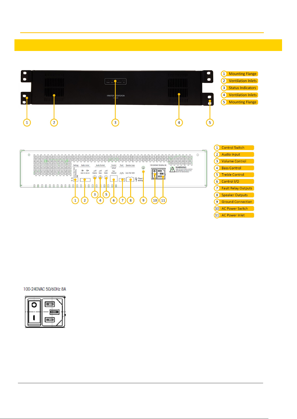
Figure 1: Amplifier Front Panel
Figure 2: Amplifier Rear Panel
2.1. Cabinet
The amplifier is prepared for mounting in a standard 19” rack and will occupy 2HU in height. The amplifier
can also be free-standing on a level, open surface. The amplifier has a built-in cooling fan but the front and
back must be kept free of objects in order to secure sufficient air flow.
2.2. Power
The amplifier is powered by 100-240 VAC 50/60 Hz mains. There is a mains circuit breaker on the cabinet
rear side, and a mains fuse on the Main Board inside the cabinet. The fuse value is 8A. The amplifier must
be grounded with the main cable, or with a 2.5 mm
proven good PE grounding point.
2
wire between the amplifier’s ground terminal and a
4 EA1400/1600 Installation & User Manual A100K11939
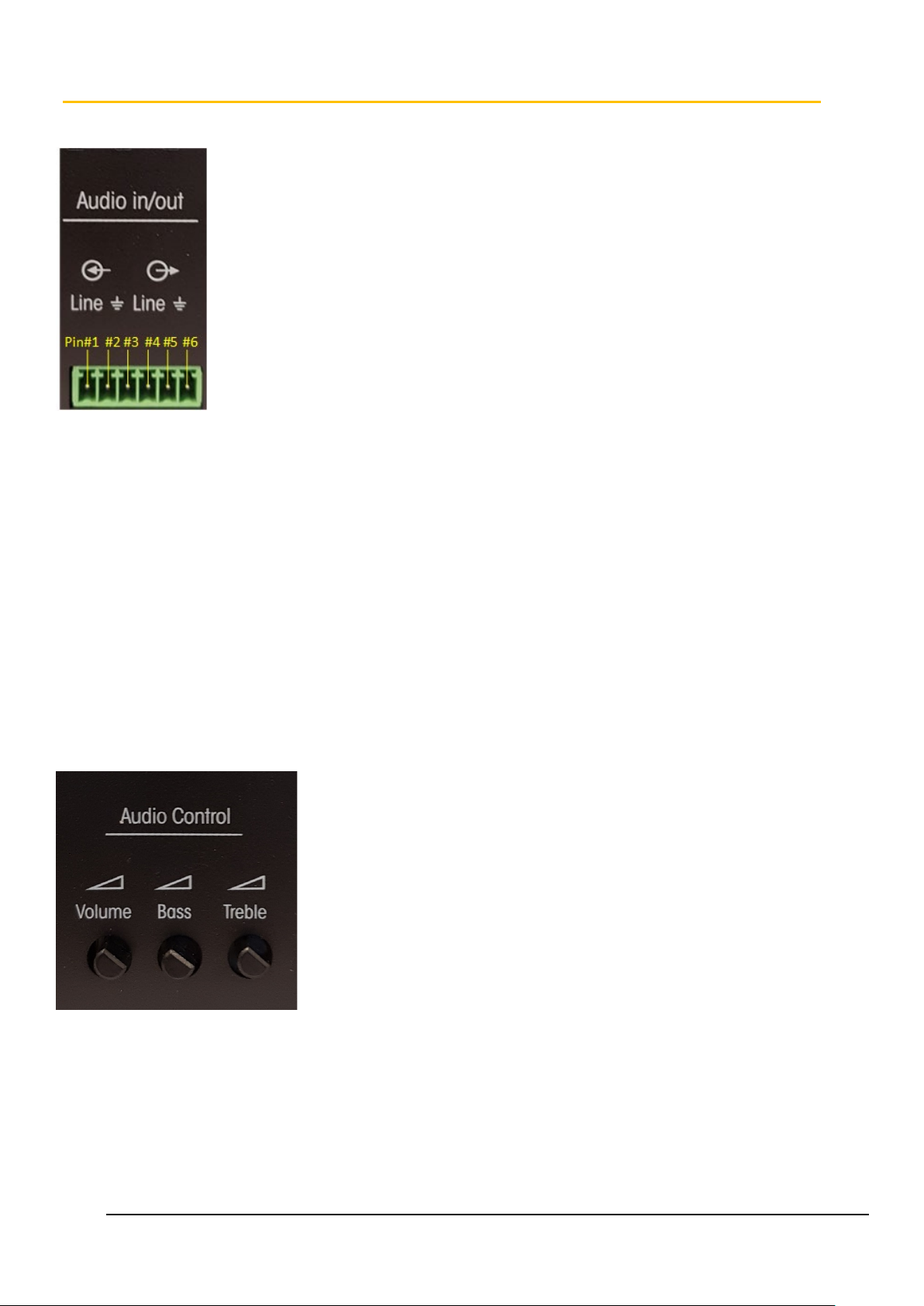
2.3. Audio Input
This connector is used as a line input and output with a 6-pin Phoenix MiniCombi connector:
Pin#1 & Pin#2: Balanced Line IN audio input for public announcements, alarm messages,
background music, etc.
Pin#3: Line IN audio cable shielding; connected to chassis ground.
Pin#4 & Pin#5: Balanced Line OUT for output daisy chaining of audio signal. It is dependent on the
source impedance how many amplifiers can be driven with the same audio signal. Using a low
impedance source, it is possible to drive 5 amplifiers or more with this daisy-chain method.
Pin#6: Line OUT audio cable shielding; connected to chassis ground.
For more information and application example, please refer to section 3.5. Input Connection.
2.4. Audio Control
Volume adjustment can be done through the potentiometers for Volume, Bass, and Treble.
If the Volume potentiometer is set to the mid-point position and 1Vrms/1kHz is used as input
signal, 100Vrms should be measured on the “100V” loudspeaker output.
For Volume, the control range is between -14dB and +6dB.
For Bass and Treble, the control range is between 0dB and -10dB.
A100K11939 EA1400/EA1600 Installation & User Manual 5
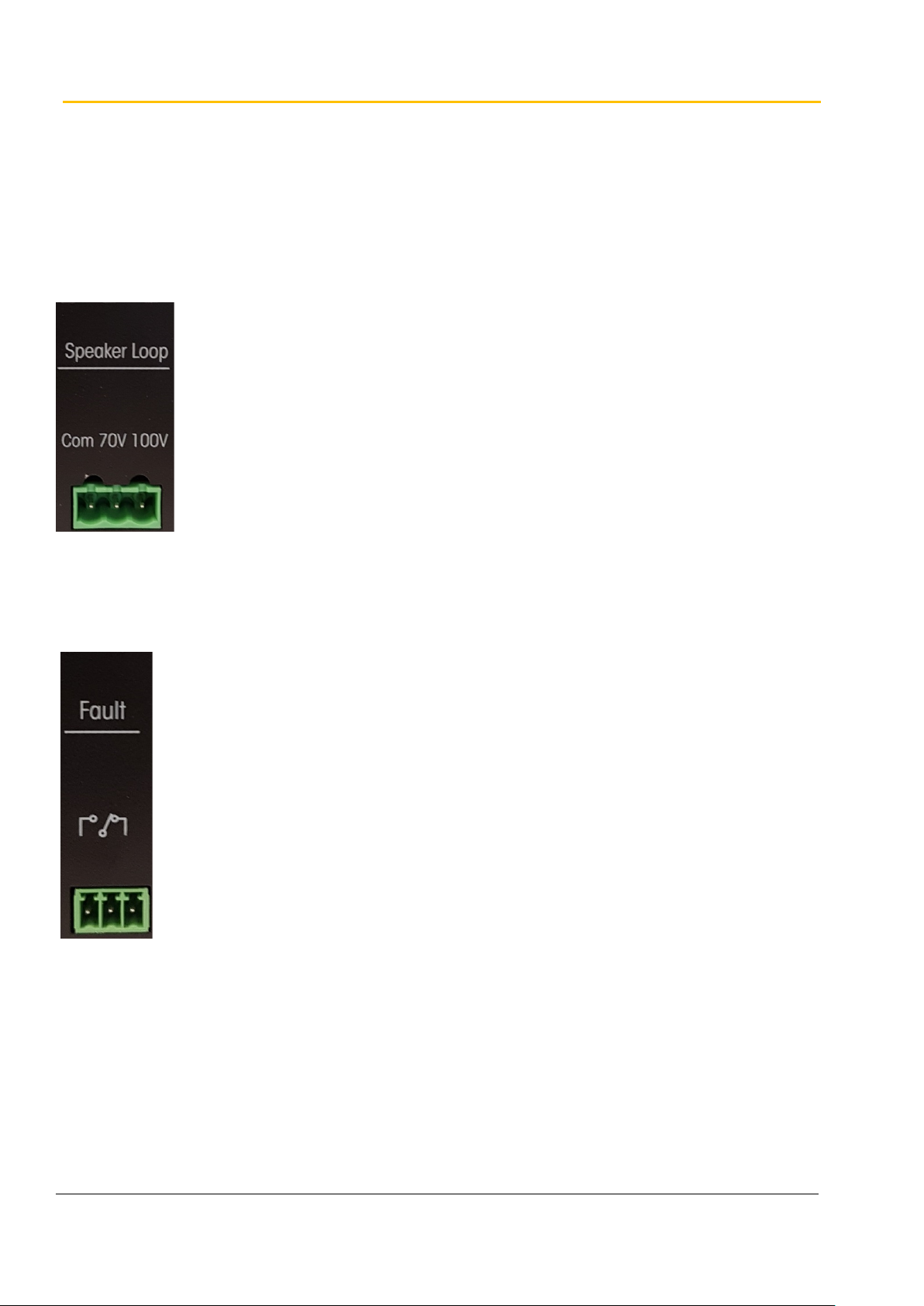
2.5. Loudspeaker Outputs
The loudspeaker outputs have a 3-pin Phoenix 5.08 mm connector:
Speaker Loop: full power output available on the 100V or 70V constant voltage line
2
Max. cable cross section: 12 AWG / 2.5 mm
For more information and application example, please refer to section 3.6. Loudspeaker Connections.
2.6. Fault Relay
Fault Relay: NO/NC contacts of a built-in relay is available for remote warning devices. The relay is
activated during various fault conditions such as shorted speaker lines, ground fault,
overtemperature or overload on audio output.
For more information and application example, please refer to section 3.8. Optional Connections.
6 EA1400/1600 Installation & User Manual A100K11939
 Loading...