


CLWT-135T Speaker Installation Guide
Item Number
Item Name
Description
2131000133
CLWT-135T
Ceiling Speaker WT, 100V, IP55, 6W
1 Dimensions & Mounting Procedure
1. Cut out a hole in the ceiling at Ø116 mm.
2. Lead the cable through the M20 cable glands and tighten them.
3. After connections are done, mount the back cover with the two screws provided.
4. Fasten the speaker to the ceiling by using the 2x fastening spring clamps.
5. Knock out and use the 3x fastening holes at Ø4.2 mm if additional tightening is required.
Make sure that the cables have the necessary length for maintenance.
Observe
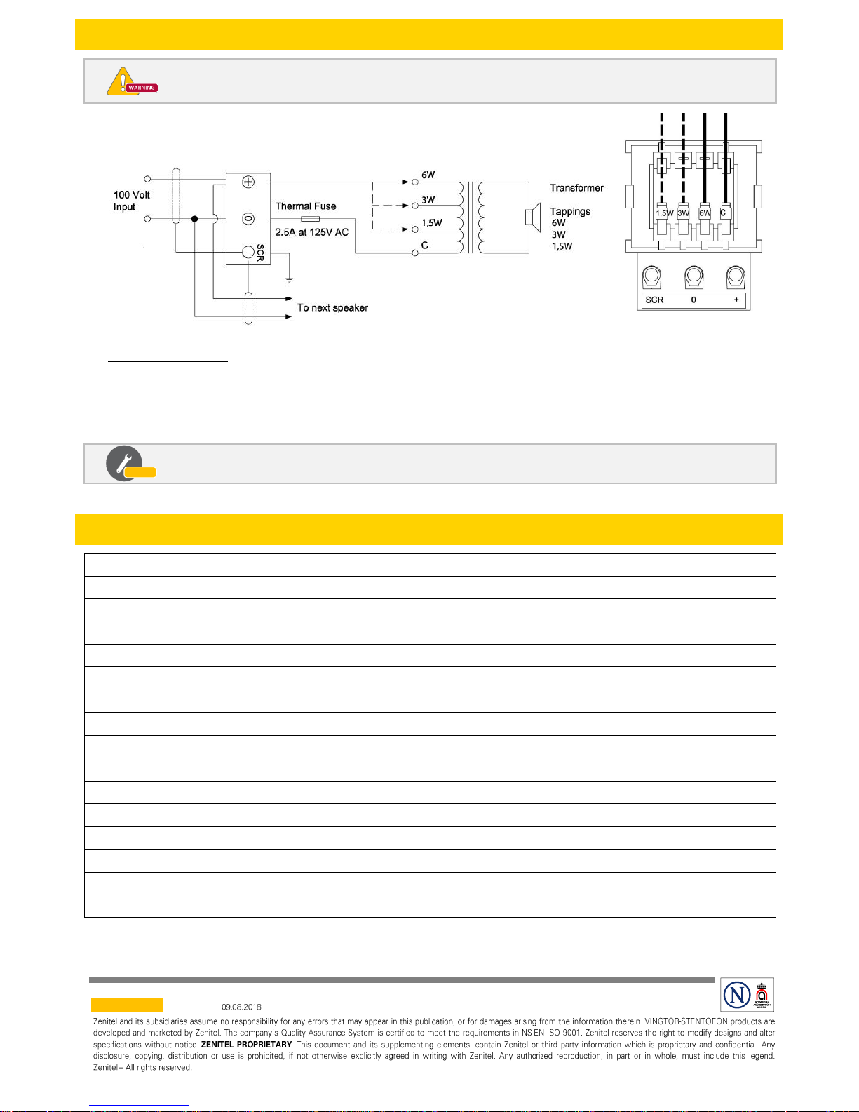
2 Connections
Do NOT open the speaker when energized.
Cable Requirements
Approved ship’s cable 0.5 – 1.5 mm
2
with outer braided tinned copper shield. The shield must be
interconnected and grounded in a common ground point in the central unit only.
Optional tappings at 1.5W, 3W or 6W by changing cable positions as shown in the figure. C is common.
The speaker must be connected to a 100V voltage amplifier line.
3 Specifications
Dimensions (Diameter x Depth)
Ø136 x D130 mm
Cut Out Dimension (Diameter)
Ø116 mm
Suspension / Mounting
Spring Clamp
IP Rating
IP-55
Operating temperature range
-20 ℃ ~ + 70 ℃
Rated / Max Power
6W / 12W
Power Tappings
100 V 6 - 3 - 1.5 W
Sound Pressure Level (400,500,600,700HZ,1W/1M)
88 dB ±3dB
Frequency Range
200 – 20000 Hz
Speaker
2.5-inch paper cone with cloth surround (moisture resistant)
Connections
Ceramic Terminal Block with Thermal Fuse
Baffle Material
ABS, UL94 Vo, White RAL 9010
Grille Material
ABS, UL94 Vo, White RAL 9010
Back Cover
ABS, UL94 Vo, White RAL 9010
Cable Glands
2x M20
Weight
0.62 kg
Observe
A100K11810
DOC NO.
customer.service@zenitel.com
 Loading...