

Page 1
TECHNICAL MANUAL
AlphaCom XE
Installation, Configuration & Operation
A100K10805
Page 2

2
A100K10805
AlphaCom XE - Installation, Conguration & Operation
About this Document
Document Scope
This document provides a detailed step-by-step guide to the installation
and conguration, as well as useful information on system management
and operation, of the AlphaCom XE Audio Server product range.
This document should provide adequate information for setting up the
system and getting it up and running.
Product Information
Product Part Number
AlphaCom XE1 Audio Server 1009601002
AlphaCom XE7 Audio Server 1009608000/1009608100/1009608106/1009608300
AlphaCom XE20 Audio Server 1009621000
AlphaCom XE26 Audio Server 1009627000/1009627001/1009627002
Publication Log
Rev. Date Author Comments
1.0 21.10.2010 HKL Published
1.1 24.11.2010 HKL Revised LCM gures
1.2 4.3.2011 HKL XE7 backplane g.
1.3 18.3.2011 HKL AMC board jumpers
1.4 16.7.2012 HKL AlphaWiki ref
1.5 28.8.2013 HKL Port pin-out, RIO cabling
1.6 31.01.2014 ER Last § 2.2.3 deleted
1.7 8.6.2015 HKL Battery § 2.2.7
Related Documentation
For further information, refer to the following documentation:
Doc. no. Documentation
A100K10176 RIO Remote Input/Output Unit
A100K10300 Prison Technical Manual
A100K10390 SIP GSM Gateway MV-370
A100K10333 SIP Analog Gateway AudioCodes MP-114/118
A100K10313 Network Design Guide
A100K10590 Billing System Conguration Guide
A100K10610 LCM - Line Connection Module
A100K10652 IP DECT Installation & Conguration
A100K10674 API STENTOFON SDK
A100K10777 IP DECT Quick Conguration
A100K10788 IP Master Station Installation & Conguration
A100K10803 IP Substation Installation & Conguration
A100K10845 SoftClient Installation & Operation
A100K11194 Turbine Stations Technical Manual
Page 3

3
AlphaCom XE - Installation, Conguration & Operation
A100K10805
Contents
1 The AlphaCom XE System ..................................................................................................6
1.1 Flexible, Secure and Safe Operation .....................................................................................7
1.1.1 Restricted management access ...........................................................................................7
1.1.2 Separate management interface ..........................................................................................7
1.1.3 Internal rewall ......................................................................................................................7
2 Getting Started ..................................................................................................................... 8
2.1 Making a Network Plan .......................................................................................................... 8
2.2 Unpacking and Installing Hardware .......................................................................................9
2.2.1 Installing the AlphaCom XE1 cabinet ....................................................................................9
2.2.2 Installing the AlphaCom XE7 cabinet ....................................................................................9
2.2.3 Installing the AlphaCom XE20 cabinet ................................................................................10
2.2.4 Installing the AlphaCom XE26 cabinet ................................................................................10
2.2.5 LCM - Line Connection Module ..........................................................................................11
2.2.6 Installing feature boards ..................................................................................................... 11
2.2.7 AMC-IP - AlphaCom Module Controller Board ....................................................................12
2.2.8 APC - Program and Clock Board ........................................................................................ 13
2.2.9 ASLT - Subscriber Line Board ............................................................................................13
2.2.10 ATLB - Telephone Line Board ............................................................................................. 14
2.2.11 ATLB-12 - Telephone Line Board ........................................................................................15
2.2.12 AGA - General Purpose Audio Interface ............................................................................. 16
2.3 Performing a Cold Start .......................................................................................................16
2.3.1 Cold start procedure ........................................................................................................... 16
2.3.2 Cold start AMC application only (retain IP setting) ..............................................................17
2.4 Modifying Factory Default Settings ......................................................................................17
2.5 Default Directory and Feature Numbers ..............................................................................17
2.5.1 Station numbers ..................................................................................................................17
2.5.2 Class of Service (CoS)........................................................................................................17
2.5.3 Features during connection ................................................................................................18
2.5.4 Voice and display messages ..............................................................................................18
2.5.5 Station functions ................................................................................................................ 19
2.5.6 System maintenance .......................................................................................................... 20
2.5.7 Control room stations ..........................................................................................................20
2.5.8 Mail queue navigation ......................................................................................................... 21
2.5.9 Dual Display station ............................................................................................................21
2.5.10 Telephone functions ............................................................................................................21
2.5.11 AlphaNet .............................................................................................................................21
3 AlphaWeb XE .....................................................................................................................22
3.1 Connecting to AlphaCom using AlphaWeb ..........................................................................22
3.1.1 Saving and applying changes ............................................................................................ 23
3.2 Changing Default User Name and Password ......................................................................23
3.3 Installing License Keys ........................................................................................................24
3.4 IP Conguration ...................................................................................................................24
3.4.1 Overview ............................................................................................................................. 24
3.4.2 IP interfaces ........................................................................................................................ 24
3.4.3 Congure IP routing ............................................................................................................ 25
3.4.4 Internal rewall ....................................................................................................................25
4 AlphaPro ............................................................................................................................. 26
4.1 Overview .............................................................................................................................. 26
4.1.1 AlphaPro versions ...............................................................................................................26
4.1.2 Backwards compatibility......................................................................................................26
Page 4

4
A100K10805
AlphaCom XE - Installation, Conguration & Operation
4.1.3 PC requirements ................................................................................................................. 27
4.2 Getting Started with AlphaPro ..............................................................................................27
4.2.1 PC setup .............................................................................................................................27
4.2.2 Insert the HW dongle ..........................................................................................................27
4.2.3 Connect a PC to the server ................................................................................................27
4.3 Dening Network and Exchange..........................................................................................28
4.3.1 Initial programming ............................................................................................................. 28
4.3.2 Add network or exchange ...................................................................................................28
4.4 Data Communication ...........................................................................................................29
4.4.1 Establishing data communication .......................................................................................29
4.4.2 Send information to the exchange ......................................................................................29
4.4.3 Get information from the exchange ....................................................................................29
4.5 Communication Window Actions..........................................................................................29
4.6 AlphaPro Menu Structure.....................................................................................................30
5 StationConguration ........................................................................................................32
5.1 Conguration in AlphaPro .................................................................................................... 32
5.2 Additional IP and SIP Station Conguration ........................................................................34
5.3 IP DECT SIP Station Conguration......................................................................................34
6 AlphaNet .............................................................................................................................35
6.1 Overview .............................................................................................................................. 35
6.2 VoIP AlphaNet Conguration ...............................................................................................36
6.2.1 Overview ............................................................................................................................. 36
6.2.2 Insert AlphaNet license ...................................................................................................... 36
6.2.3 Create all the exchanges in the AlphaNet ...........................................................................36
6.2.4 Create AlphaNet data routing ............................................................................................. 36
6.2.5 Create AlphaNet audio channels ........................................................................................38
6.2.6 Cluster node programming .................................................................................................38
6.2.7 Update the directory in each exchange .............................................................................. 39
7 Multi-Module Network ........................................................................................................41
7.1 Overview .............................................................................................................................. 41
7.2 Installation ..........................................................................................................................41
8 External Communication...................................................................................................43
8.1 SIP Trunk License ................................................................................................................ 43
8.2 Gateway Conguration ........................................................................................................43
8.3 AlphaCom Congurations ................................................................................................... 43
8.3.1 AlphaWeb Congurations ...................................................................................................43
8.3.2 Insert SIP Trunk licenses ....................................................................................................44
8.3.3 Firewall (lter) settings ........................................................................................................ 44
8.4 AlphaPro Conguration .......................................................................................................44
8.4.1 Create a SIP Trunk Node ................................................................................................... 44
8.4.2 Dene the AlphaCom/SIP routing ...................................................................................... 44
8.4.3 Create Prex number ..........................................................................................................45
8.4.4 Update the exchange ..........................................................................................................45
8.5 Billing System ......................................................................................................................45
9 Audio Messaging ...............................................................................................................47
9.1 Stored Voice Messages ....................................................................................................... 47
9.1.1 Message identication ........................................................................................................48
9.1.2 ASVP software module ....................................................................................................... 48
9.1.3 ASVP board .......................................................................................................................48
9.2 Customized Message Upload .............................................................................................. 49
9.2.1 Upload messages from AlphaWeb ......................................................................................49
Page 5

5
AlphaCom XE - Installation, Conguration & Operation
A100K10805
9.2.2 Record message from a station .......................................................................................... 51
9.2.3 Licensing .............................................................................................................................51
9.2.4 Supported audio le formats ............................................................................................... 52
9.3 Recall ................................................................................................................................... 52
9.3.1 Directory numbers ..............................................................................................................52
9.3.2 User interface .....................................................................................................................53
9.3.3 Optional settings ................................................................................................................53
9.3.4 Simultaneous recall operations ..........................................................................................54
9.3.5 Hardware and software requirements .................................................................................54
9.4 Auto-attendant .....................................................................................................................54
9.4.1 Conguration .....................................................................................................................55
9.4.2 Hardware and license requirements ...................................................................................56
10 System Monitoring.............................................................................................................57
10.1 System Logging ...................................................................................................................57
10.1.1 Local log le and AlphaWeb ................................................................................................58
10.1.2 System clock and event time stamps ................................................................................. 59
10.2 System Information and Statistics........................................................................................60
10.2.1 SNMP MIBs ........................................................................................................................60
10.2.2 System information ............................................................................................................. 60
11 Upgrade & Backup ............................................................................................................. 61
11.1 Software Upgrade ................................................................................................................ 61
11.2 Conguration Backup and Restore ...................................................................................... 61
12 Appendix - Technical Data ................................................................................................ 62
12.1 Specications .......................................................................................................................62
12.2 Physical Numbers ................................................................................................................ 63
12.3 ASLT & AGA Board Positions ..............................................................................................63
12.4 Switches and Jumpers .........................................................................................................64
12.4.1 AMC-IP ...............................................................................................................................64
12.5 Port Pin-Out .........................................................................................................................65
12.5.1 RIO controller unit connection ............................................................................................ 67
Page 6
6
A100K10805
AlphaCom XE - Installation, Conguration & Operation
1 The AlphaCom XE System
The AlphaCom XE Audio Server with HD Voice system provides easy
to use, secure and powerful system management capabilities targeted
towards meeting the needs and demands of the end-user.
The management system has an open and exible architecture that
caters to multiple tools and technologies.
The management tools and functions come with different levels of
complexity, running the gamut from small standalone systems to large
integrated management systems.
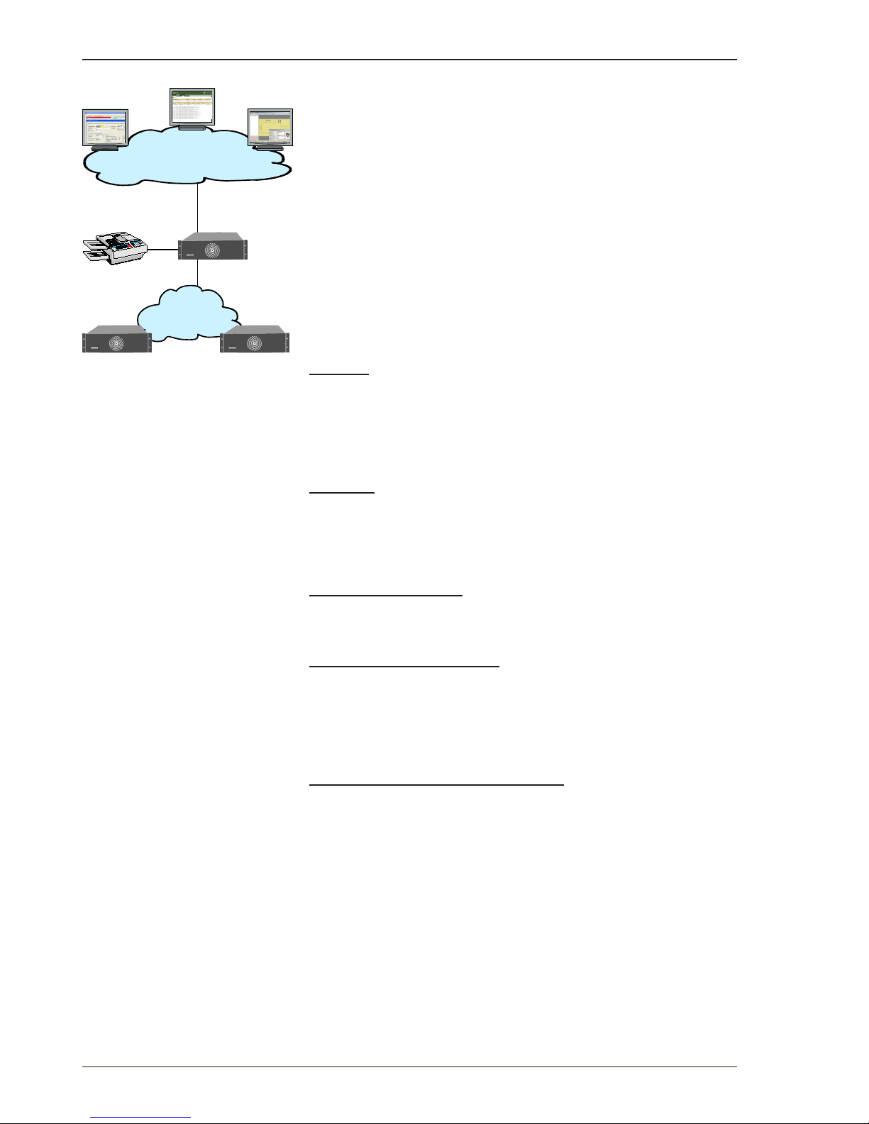
The main tools and functions are:
● AlphaPro
● AlphaWeb
● Logging and monitoring
● System upgrade and Backup
● Interface to 3rd party management tools
AlphaPro
AlphaPro is the professional tool for conguration of the AlphaCom
XE system. It is self contained, simple to install and use. When a new
server is to be congured, it is given a working default factory setting
which may be modied later. AlphaPro works over IP or the local data
port (RS232).
AlphaWeb
AlphaWeb is an embedded web server running on the AlphaCom XE
server. It allows users to log in using a standard web browser such as
Internet Explorer or Firefox to operate and manage the AlphaCom XE
system.
Logging and monitoring
AlphaCom XE comes with powerful logging and monitoring functions,
providing the user with good oversight of system status and events.
Software and system upgrade
AlphaCom XE comes with powerful software and system upgrade
capabilities. New software packages are easily uploaded and stored
to ash via AlphaWeb. In addition, older AlphaCom systems can be
upgraded to AlphaCom XE with only limited hardware changes and
automatic upload and conversion of the old customer database.
Interface to 3rd party management tools
AlphaCom XE has a wide range of open interfaces that supports
integration with 3rd party management applications. The 3rd party
management application may interface AlphaCom XE using SNMP
(Simple Network Management Protocol), syslog, HTTP (Hyper Text
Transfer Protocol), NTP (Network Time Protocol), and OPC (open
connectivity via open standards), as well as legacy STENTOFON data
protocols.
AlphaPro
AlphaWeb
3rd party
application
AlphaNet
Administration
Network
Serial
data
Separate
Management
Interface
RS232
AlphaCom
AlphaCom
AlphaCom
Printer
AlphaCom XE7AlphaCom XE7
AlphaCom XE7
Page 7
7
AlphaCom XE - Installation, Conguration & Operation
A100K10805
1.1 Flexible, Secure and Safe Operation
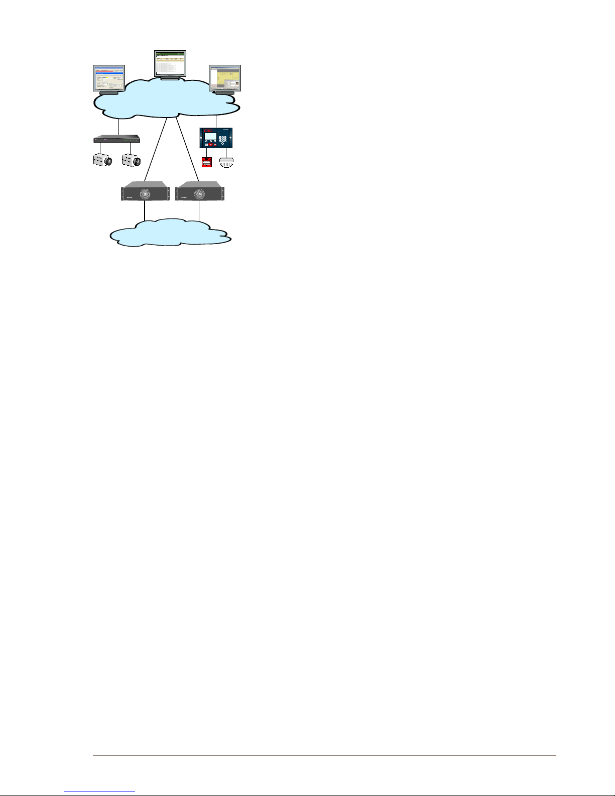
Critical Communication over IP (CCoIP®) is our solution for VoIP
with IP services and applications integrating security and reliability
functionalities required in critical situations. The critical communication
solution can no longer be regarded as a totally independent system
isolated from data networks and their associated challenges.
The AlphaCom system provides carrier class system availability and
protects resources in an IP environment by using embedded IP security
mechanisms. The main AlphaCom XE security mechanisms are:
● Restricted management access
● Separate management interface
● Internal rewall
1.1.1 Restricted management access
All users need to authenticate themselves before gaining access
to management services. The authentication process uses an MD5
authentication routine.
1.1.2 Separate management interface
AlphaCom XE comes with a separate Ethernet interface which can
be dedicated to management. This allows the administrator to build a
separate administration VLAN that is dedicated only to administrators.
1.1.3 Internalrewall
AlphaCom XE has an internal rewall allowing the network administrator
to open and close IP services that are allowed access to AlphaCom XE
from the different networks.
AlphaCom XE comes with the most restrictive rewall settings by
default.
To change these settings, log into AlphaWeb as described in section 3.1.
● Select SystemConguration>Filters
WAN/LAN
VoIP Netvork
LAN
Administration
Network
ALLEGIANT
Video System
Code Out
Alarm
Status
Battery Low
Power
POWER
FAULT
SYSTEM FAULT
TEST
DISABLEMENTS
MENU
ALARMS
ALARM
ABC
DEF GHI
JKL
MNO PQR
STU
_VW
XYZ
7
8 9
4
5
6
1
2
3
0
ServoMaster
NEXT
ALARM
SERVOTEKNIKK
CCTV Fire Alarm
AlphaCom
AlphaCom XE7AlphaCom XE7
Page 8
8
A100K10805
AlphaCom XE - Installation, Conguration & Operation
2 Getting Started
This section is a step-by-step guide to getting the AlphaCom XE system
up and running.
1. Sketch a network overview
2. Unpack and install hardware
3. Perform cold start
4. Connect to AlphaWeb
5. Congure IP Settings
6. Change default user name and password
7. Enter the license key
8. Modify default settings (optional)
9. Perform a system backup
The AlphaCom XE servers are shipped with a default factory setting and
the system will work straight out of the box. If no changes to the default
factory settings are required, it is enough to perform steps 1 to 6 to set
up a working system.
Some changes to the default factory settings are often required, for
instance if the default numbering plan and naming in the directory shall
be updated to reect the oors in a building, then the optional steps
should also be performed.
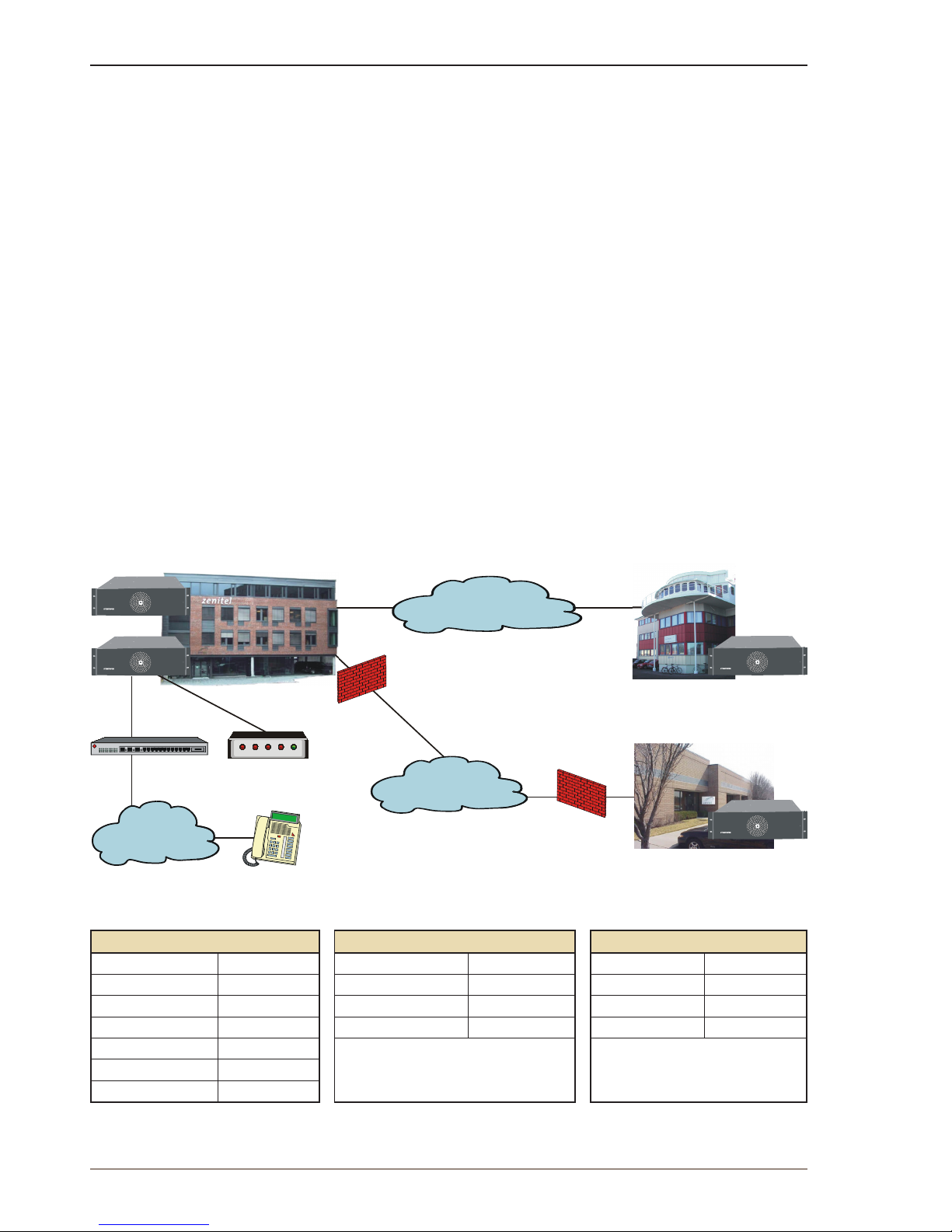
2.1 Making a Network Plan
Make a plan of the network topology as shown in the example below.
Oslo head office
SIP ISDN
Gateway
iPBX
Public
telephone
network
Internet
VPN (IPsec)
WAN
Internet Service Provider
Horten branch office
USA branch office
AlphaCom XE7
AlphaCom XE7
AlphaCom XE7
AlphaCom XE7
LAN Oslo LAN Horten LAN USA
Network IP 10.0.1.0 Network IP 10.0.5.0 Network IP 10.0.10.0
Mask 255.255.255.0 Mask 255.255.255.0 Mask 255.255.255.0
Router Oslo 10.0.1.1 Router Horten 10.0.5.1 Router USA 10.0.10.1
AlphaCom Oslo 1 10.0.1.10 AlphaCom Horten 1 10.0.5.10 AlphaCom USA 1 10.0.10.10
AlphaCom Oslo 2 10.0.1.11
iPBX 10.0.1.20
SIP ISDN Gateway 10.0.1.21
Page 9
9
AlphaCom XE - Installation, Conguration & Operation
A100K10805
2.2 Unpacking and Installing Hardware
Remove all hardware from the packing boxes and inspect each item to
ensure that they have not been damaged during shipping. In addition,
check that the packing boxes contain all the items you ordered. If you
discover or suspect any damage, contact your distributor immediately.
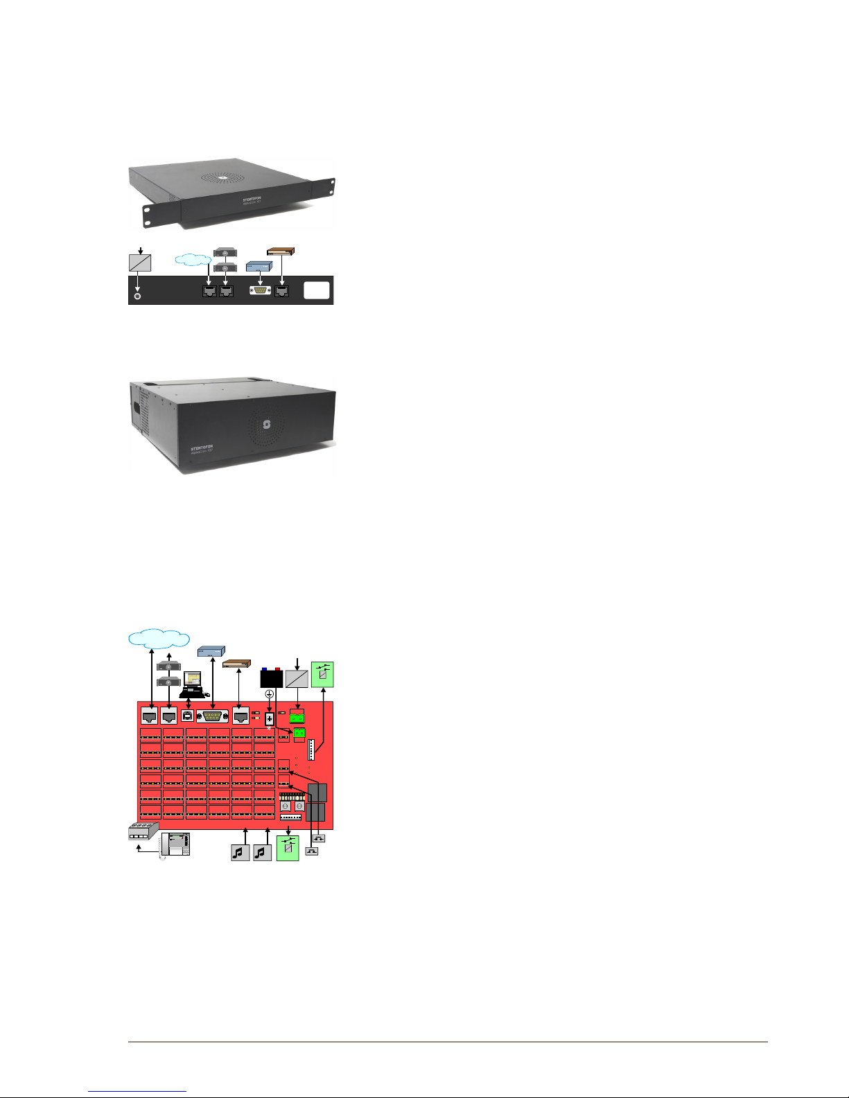
2.2.1 Installing the AlphaCom XE1 cabinet
More information is found in Datasheet A100K10798
The cabinet should be mounted on a shelf or in a 19” rack. It contains
one AMC-IP processor board only. The server includes a power board.
● All cables are terminated to connectors at the rear of the cabinet.
● Two RJ-45 Ethernet terminals are used for IP LAN, WAN, Internet
and AlphaNet IP communication.
● The serial ports with RS232 and RS422 interfaces are used for
connecting to equipment using these protocols.
● The unit is powered from a 90-240 VAC via a 5 VDC power supply.
2.2.2 Installing the AlphaCom XE7 cabinet
More information is found in Datasheet A100K10799
The cabinet can be wall or shelf mounted or mounted in a 19” rack. It
has room for installation of one AMC-IP processor board and up to 6
feature boards. The server also includes a power board and a cooling
fan.
● All cables are terminated to connectors on the backplane.
● The two-pair star wired intercom cables are connected using
pluggable screw connectors.
● Two RJ45 Ethernet terminals are used for IP LAN, WAN, Internet and
AlphaNet IP communication.
● The serial ports with RS232 and RS422/485 interfaces are used for
connecting to equipment using these protocols.
● The two NO switches on the RCI connectors can execute
programmable functions.
● The 12 RCOs are connected to optional MRBD relay boards and can
be programmed to execute functions such as door control.
● Connectors 5 and 6 on the rst ASLT line board are enabled for
program distribution. Additional programs can also be connected
to individual ASLT ports via the interface board FBSAR, with 6
programs per board.
If line points 5 and/or 6 are to be used as subscriber line points,
follow the connection procedure for AlphaCom XE7 in section 2.2.9.
● The server is normally powered from the mains via a 24 VAC
transformer. The 6 A type 203 0010 260 can serve up to 24
subscribers, while the 11 A type 203 0010 270 is needed for a full
cabinet of 36 subscribers.
● Battery backup power is connected to the 24 VDC input plug.
● The ground terminal is connected to the cabinet.
The jumper is used to provide galvanic connection between the
cabinet and 0V (DC-GND) or isolation from 0V (AC-GND). AC-GND
is only used on marine vessels.
Serial Port 1 Serial Port 0
Eth 0 Eth 1
5 VDC
1
1 1
230 VAC
5 VDC
MAINS
AlphaCom XE7
AlphaCom XE7
36
31
1
P5
P6
N1
N5
N4
N2
N3
C CD D
24V DC
Out
24V AC In
+
24V DC
In
+
_
_
Program level
RCO 1 - 6
1
RCO 7 - 12
P6
P5
RCI 2
RCI 1
Eth 0
Eth 1
Serial Port 0
Serial Port 1
USB
485 422
1
12
65
18
24
30
7
13
19
25
1
2
3
230VAC
24VAC
MAINS
24VDC
A B C D
MRBD
7....12
MRBD
1....6
1 2
ACGND
DCGND
AlphaCom XE7
AlphaCom XE7
12 3 45
STENTOFON
VMPD619
*
#
1 2
3
4
5 6
7
8
9
0 C
M
VINGTOR
Page 10
10
A100K10805
AlphaCom XE - Installation, Conguration & Operation
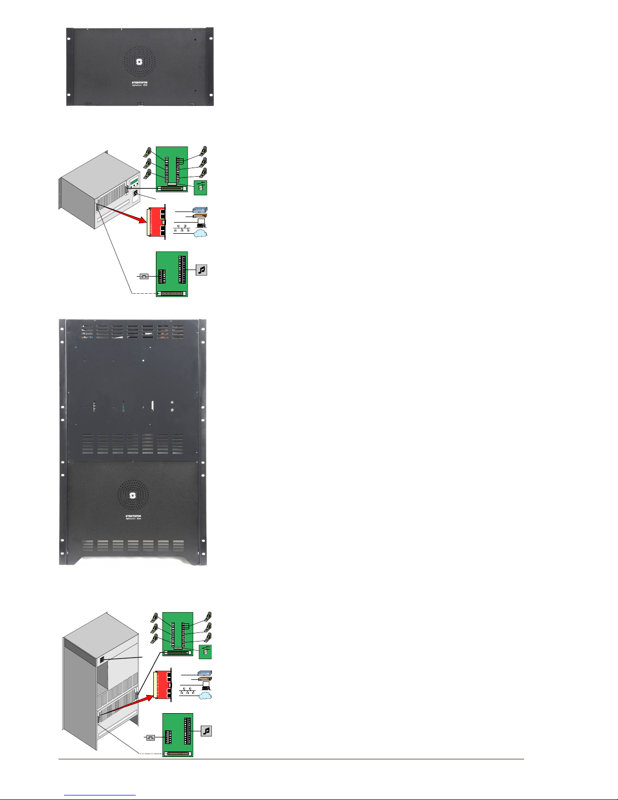
2.2.3 Installing the AlphaCom XE20 cabinet
More information is found in Datasheet A100K10800.
The cabinet is intended for mounting in a 19” rack. It has room for
installation of 20 circuit boards in total: one AMC-IP processor board,
one APC program & clock board, and up to 18 feature boards. The
server also includes a mains power supply.
● Up to 4 units may be mounted in one 19” rack if sufcient ventilation
is provided. It is recommended to mount a 24 VDC cooling fan
module on top of each server unit.
● The two-pair star wired intercom cables are connected to connection
boards or an LCM Line Connection Module on the cabinet DIN rail or
in a separate distribution eld.
● Each subscriber line card provides 6 freely programmable Remote
Control Outputs (RCOs).
● Two RJ45 Ethernet terminals on the IP lter board are used for IP
LAN and WAN communication.
● The serial ports with RS232 and RS422/485 interface are used for
connecting to equipment using these protocols.
● 6 program distribution sources can be connected to the APC
board via an optional program connection board or to an LCM Line
Connection Module. Up to 64 extra programs may be added using
AGA boards with 16 programs per board.
● The optional program connection board or LCM module has input for 6
Remote Control Inputs (RCIs) which can initiate programmed actions.
● The server is powered from the mains. The power supply, APWR,
runs on 90-270 VAC.
See the manual A110K10610 Line Connection Module for details.
2.2.4 Installing the AlphaCom XE26 cabinet
More information is found in Datasheet A100K10317.
There are three standard cabinet models: 19” rack mounting, oor
cabinet, and oor cabinet with distribution eld.
The cabinet has room for installation of 26 circuit boards in total: one
AMC-IP processor board, one APC program & clock board, and up to 24
feature boards. The server also includes a mains power supply and a
cooling fan.
● The two-pair star wired intercom cables are connected to connection
boards or LCM Line Connection Modules.
● There is one Remote Control Output (RCO) per subscriber point on
the connection board which can be programmed to perform actions
via an optional relay board. The LCM module has relay output for 6
RCOs while additional RCOs require optional relay boards.
● Two RJ45 Ethernet terminals on the IP lter board are used for IP
LAN and WAN communication.
● The serial ports with RS232 and RS422/RS485 interfaces are used
for connecting to equipment using these protocols.
● 6 program distribution sources can be connected to the APC
board via an optional program connection board or an LCM Line
Connection Module. Up to 64 extra programs may be added using
AGA boards, with 16 programs per board.
● The optional program connection board or LCM module has input
for 6 Remote Control Inputs (RCIs) which can initiate programmed
actions.
● The server is powered from the mains. The power supply, APWR,
runs on 90-270 VAC.
RS232
RS232/422/485
USB
Eth1
Eth0
IP FILTER BOARD
0
0
1
1
a
b
c
d
CONNECTION BOARD
123456
MRBD
1....6
GND
1...6
1...6
RCI
RCO
MAINS
PROGRAM
CONNECTION BOARD
RS232
RS232/422/485
USB
Eth1
Eth0
IP FILTER BOARD
0
0
1
1
a
b
c
d
CONNECTION BOARD
123456
MRBD
1....6
1...6
RCO
PROGRAM
CONNECTION BOARD
GND
1...6
RCI
MAINS
Page 11
11
AlphaCom XE - Installation, Conguration & Operation
A100K10805
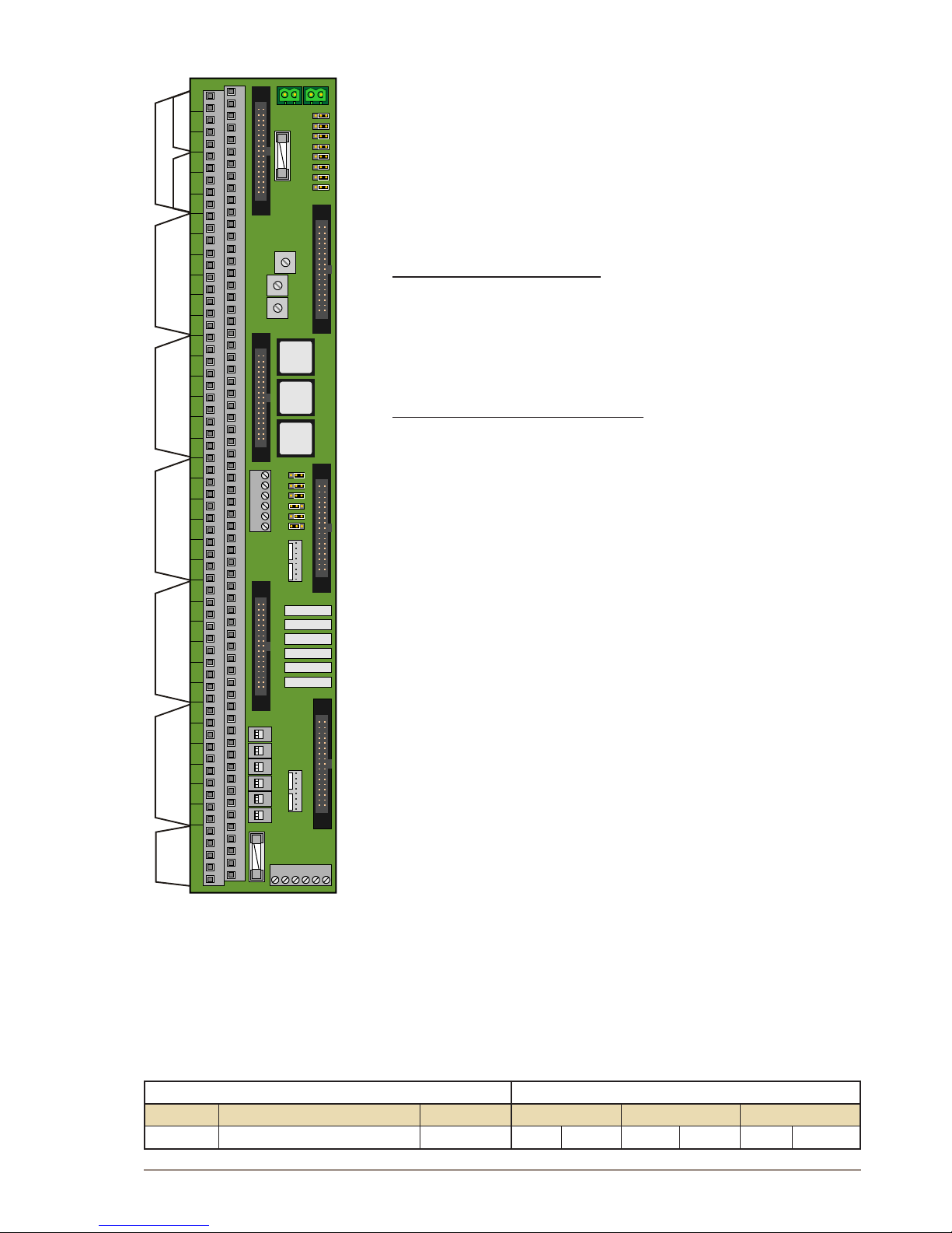
2.2.5 LCM - Line Connection Module
See the manual A110K10610 Line Connection Module for more details.
The Line Connection Module (LCM) is used for external connections for
AlphaCom XE servers with any mix of ASLT, ATLB and ATLB12 boards.
LCM is not used with XE1 and normally not used with XE7 as this server
has line connections on the backplane.
One module serves 6 subscriber boards (36 intercom stations). Up to 4
modules may be needed in a fully equipped XE26 server.
The module(s) must be mounted to DIN rail(s) on the server termination
eld and connected to the server according to the project conguration.
The LCM board will substitute
- 6 x Subscriber Connection boards (100 9930 200)
- Power Distribution board (100 9970 101)
- MRBD, Relay board with 6 RCO relays (100 9970 200)
- FBSAR, Filter and Speech Adapter board with 2 audio outputs, 1
audio input and PTT relay if these functions are used. (100 9505
000)
Each LCM board has connectors for
● 24 VDC Power
- Input
- Output
- 3 x fused outputs
- 6 x fused relay controlled RCO outputs (switch selection)
● Line-points
All subscriber line connections are made to the LCM board.
Any mix of ASLT, ATLB and ATLB-12 boards may be used.
- Max. 36 analog intercom stations with 6 x ASLT boards
- Max. 72 analog telephone lines with 6 X ATLB-12 boards
● RCO
- 6 x relay contacts, potential-free or +24 V (switch selection)
- 6 x output to optional MRBD Relay board
● RCI 1)
- 6 x closing contact inputs referred to 0 V.
● Audio program inputs
1)
- 6 x galvanic isolated 600 ohm, 0 dB lines
● Radio / Walkie-Talkie interface
1)
- Galvanic isolated adjustable audio in and out
- RCO relay can be used for PTT control
● PA audio output
- Audio output for PA with monitor intercom station in parallel
1)
The APC board must be connected to Line board connector 6.
Not used in AlphaCom XE7
2.2.6 Installing feature boards
The AlphaCom XE servers, except XE1, have room for a number of
feature boards. When using special feature boards, the maximum
number of ASLT boards is reduced accordingly.
BOARDS BOARD POSITION
Type Board Name Reference XE7 XE20 XE26
Default Possible Default Possible Default Possible
1
2
3
4
5
6
1
6
1
2
13
18
19
24
25
30
31
36
3
2
1
3
2
1
7
RCO
1-6
RCO
7-12
Line Board 1Line Board 3Line Board 4Line Board 5
Line Board 6
Line Board 2
RCIProg.
24V
in
24V aux
Relay
Page 12
12
A100K10805
AlphaCom XE - Installation, Conguration & Operation
APC
Program and Clock 100 9301 000
- - 26 - 26 -
AMC-IP
AlphaCom Module Controller 100 9202 100
7 - 25 - 25 -
ASLT
Subscriber Line 100 9101 010
1-6 - 1, 8-23 1-19 20-23
ATLB
Telephone Line - 6 lines 100 9102 000
2 1-6 1, 8-23 1-19 20-23
ATLB-12
Telephone Line - 12 lines 100 9104 000
2 1-6 1, 8-23 1-19 20-23
AGA
Audio Interface, program feed
100 9303 001
1-6 18-21 18-21
As station
1-6 20-23 1, 8-19 20-23 1-19
Hot-plug
In XE20 and XE26 servers, all boards may be inserted or removed
without switching off the power by inserting the powered RJ-11 plug
from the APC board in the hot-plug receptor found at the top of all cards
prior to removal or insertion.
● Remove the hot-plug when the board is in place.
In an XE7 server, the power must be switched off prior to removal or
insertion of boards as this server does not have the APC board or hotplug feature.
L It is strongly recommended to wear a grounded wrist-strap
when handling electronic boards to avoid electrostatic
discharges that may seriously damage the electronic circuits!
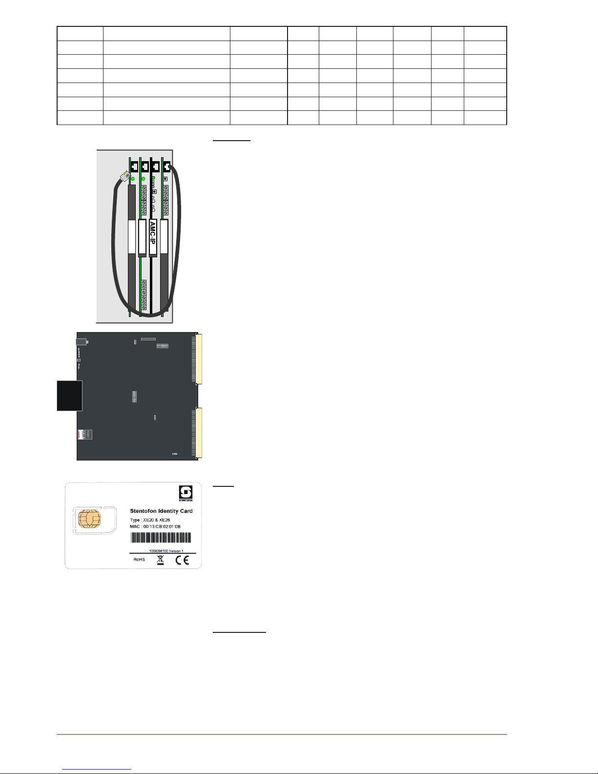
2.2.7 AMC-IP - AlphaCom Module Controller Board
All AlphaCom servers in the XE series have one AMC-IP v.11 board
delivered at shipment.
The AMC-IP v.11 board is the next generation multi-service board
developed for the STENTOFON AlphaCom XE series. The board
is made for critical communication and security solutions featuring
an embedded real-time Linux operating system, integrated media
processing engine, packet processing engine, HW encryption, and
storage module.
The AMC-IP board provides full backwards compatibility for both
software and hardware. All traditional AlphaCom services and interfaces
are supported. The board can support traditional AlphaCom feature
boards and cabinets.
STIC
The STENTOFON Identity Card (STIC) is the logical identity of the
AMC-IP board. The STIC contains the unique network identier and
network settings for the AMC-IP board, making it possible to replace the
AMC-IP with just a simple restore operation.
The AMC-IP board comes with a SIM-sized card holder for the STIC.
When delivered, the STIC resides within a regular credit card-sized
card. Detach the smaller STIC by gently pressing it out. Keep the
remaining part of the card as the MAC address programmed in the STIC
is printed on it.
There are different STICs for XE1/XE7 and XE20/XE26 servers.
3.3V Battery
The AMC-IP board features an on-board coin cell battery of type
CR2032. The battery is used for backing up the on-board RAM as well
as keeping the real-time clock running when the board is powered
down.
L CAUTION: Risk of explosion if incorrect type of battery is used.
Follow instructions for proper disposal of used batteries.
APC
AGA
ASLT
Hot-Plug
AMC-IP v.11 BOARD
Hot-Plug
Board
status
Cold boot
Ethernet
status
STIC card
Page 13
13
AlphaCom XE - Installation, Conguration & Operation
A100K10805
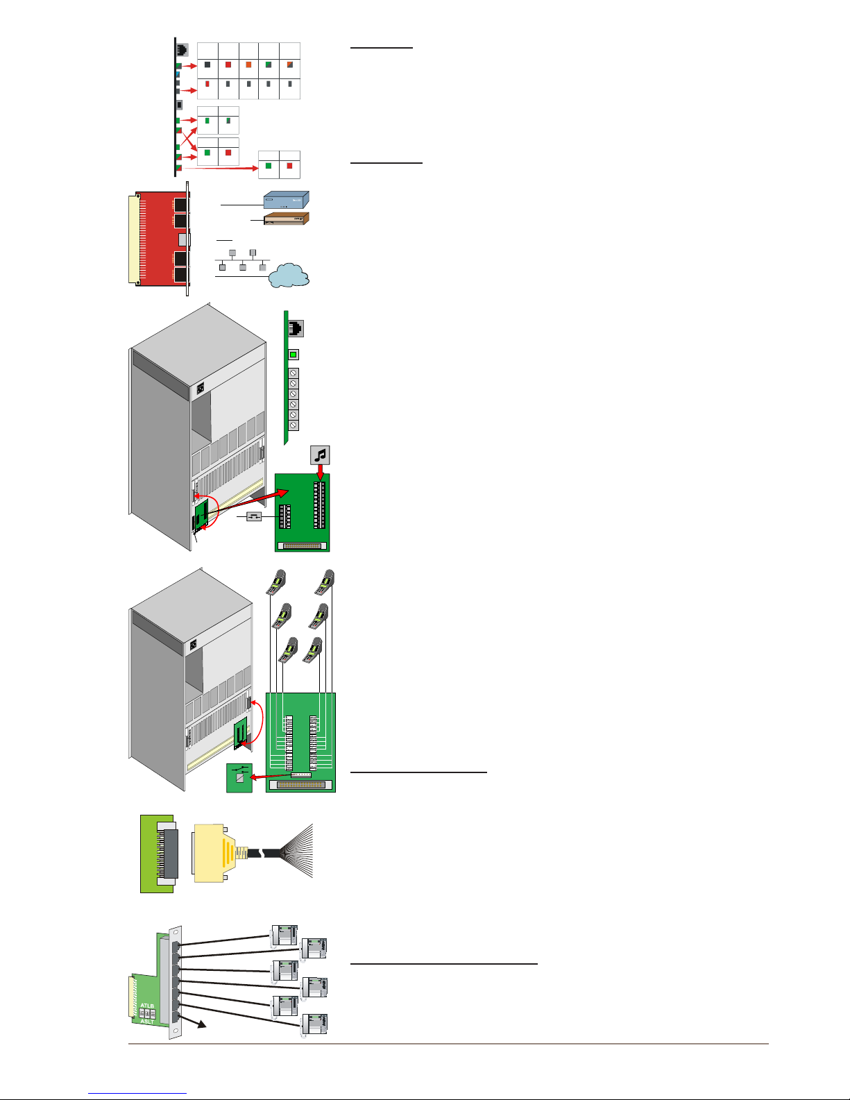
Indicators
The card has a number of LEDs to indicate the board and Ethernet
status.
See section 12.4.1 for other possible Ethernet LED indications.
Filter board
A lter and connection board, FBIP, must be inserted from the rear side
of the cabinet in the same card position as the AMC-IP card. This lter
board is not needed in AlphaCom XE1 or XE7 where all EMC lters and
external connectors are integrated in the backplane.
The USB connector is not supported in AMC-IP board 11 versions.
2.2.8 APC - Program and Clock Board
The APC Board is used in AlphaCom XE20 and XE26 to control the
backplane board clocking. It also controls the speed of the fans. This
board must be installed in position 26.
It contains circuitry for 6 audio program feed channels with galvanic
isolation. Each channel has separate input level controls.
The card has 6 RCI alarm inputs which can be used for programmed
actions. The inputs accept a closing contact referred to ground.
A reset button is used to reset and restart the entire server. The reset
LED on the AMC-IP board will turn red during reset.
An APC connection kit 100 9503 000 needs to be purchased to connect
alarm and audio sources. The kit contains a lter board, a connection
board, and an interface cable.
Further information is found in datasheet A100K10011.
2.2.9 ASLT - Subscriber Line Board
Two boards for 12 intercom subscribers are normally delivered with the
server. The maximum number of cards in one server is:
AlphaCom XE7: 6 in positions 1-6
AlphaCom XE20: 17 in positions 1, 8-23
AlphaCom XE26: 23 in positions 1-23
Each board contains circuitry for 6 subscriber connections and one
measurement channel for voice switching control.
The board provides 6 remote control software controlled outputs. The
line monitoring reports errors on all subscriber lines.
AlphaCom XE20/XE26
Intercom stations and control outputs are connected to a connection
board mounted on the server connection eld.
2 subscriber connection boards (100 9930 200) with 1.5 m connection
cables (100 9501 011) are delivered with the servers.
5 m (100 9501 021) and 10 m (100 9501 023) subscriber connection
cables with lter boards can be purchased separately if the distribution
eld is placed away from the server. These cables have a D-sub
connector for the lter board and unterminated wires for the distribution
eld. Color code is packed with the cables.
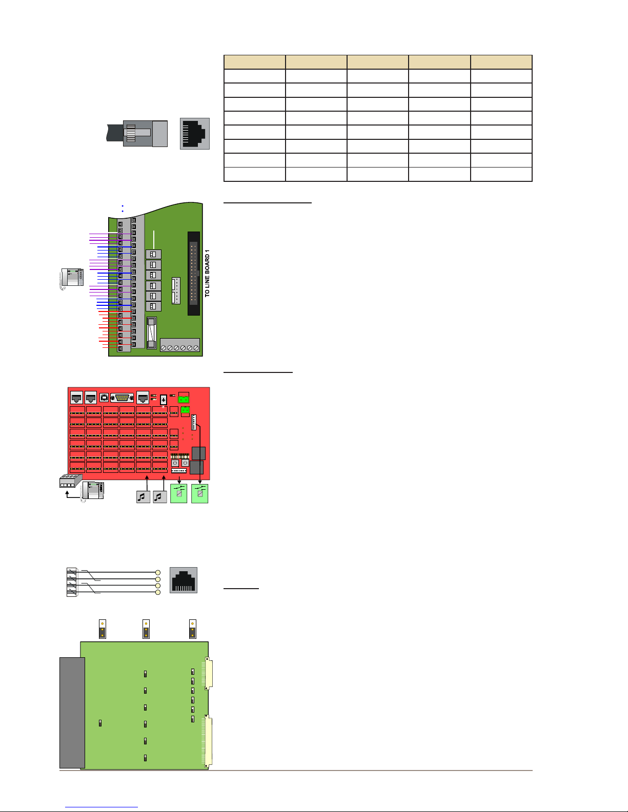
Filter card with RJ connectors
This board (100 9501 041) has RJ45 connectors for connection of 6
CAT5 installation cables to the back of the server. Station cables can be
plugged directly to this card. The 7th RJ45 outlet is for 6 RCOs.
Hot-Plug
AMC board status
Syncronisation
AUX (not in use)
Reset initiated
Link status (Eth0)
Tx/Rx (Eth0)
Flash activity
Link status (Eth1)
Tx/Rx (Eth1)
Cold start button
Exchange
reset
Software
starting
Startup
running
Normal
operation
Incorrect
NVRAM
version
OFF
OFF
OFF
OFF OFF OFF
RED
RED
RED
RED
AMBER
GREEN
flash
GREEN
flash
GREEN
GREEN
GREEN
AMBER
flash
FLASH
Link Up
Speed
negotiation
Receive
Flash1 Flash2
data
activity activity
Transmit
data
RS232
RS232/422/485
USB Future use
Eth1
Eth0
FILTER BOARD
0
0
1
1
GND
Signal
ground
1...6
1...6
RCI
PROGRAM
CONNECTION BOARD
P1
P2
P3
P4
P5
P6
P1
P2
P3
P4
P5
P6
A1
A2
A3
A4
A5
A6
Alarm
inputs
Program
sources
From APC board
Hot plug
out
Reset
Prog
ram pr
eset volume
APC board
a
b
c
d
123456
MRBD
1....6
RCO
1
2
3
4
5
6
Relay board
CONNECTION BOARD
FILTER BOARD
CONN
ECTION
FIELD
5/10m
123 45
STENTOFON
VMPD619
*
#
1 2
3
4
5 6
7
8
9
0 C
M
VINGTOR
123 45
STENTOFON
VMPD619
*
#
1 2
3
4
5 6
7
8
9
0 C
M
VINGTOR
123 45
STENTOFON
VMPD619
*
#
1 2
3
4
5 6
7
8
9
0 C
M
VINGTOR
123 45
STENTOFON
VMPD619
*
#
1 2
3
4
5 6
7
8
9
0 C
M
VINGTOR
123 45
STENTOFON
VMPD619
*
#
1 2
3
4
5 6
7
8
9
0 C
M
VINGTOR
123 45
STENTOFON
VMPD619
*
#
1 2
3
4
5 6
7
8
9
0 C
M
VINGTOR
RCO1-6
Page 14
14
A100K10805
AlphaCom XE - Installation, Conguration & Operation
The board can be used for ASLT and ATLB/ATLB-12 cards selected by
DIP switches. Switch Down is ASLT and Switch Up is ATLB or ATLB-12
RJ45 pin no. ASLT ATLB ATLB-12 RCO
1 1
2 2
3 a a1 3
4 a 4
5 b 5
6 b b1 6
7 c a2 GND
8 d b2 GND
Connection to LCM
The ASLT Subscriber Line boards are connected to the LCM via 1.5 m
connection cables (100 9501 011), one for each board.
Stations are connected to the terminal strip in the following order:
the rst station on Line Board 1 to the terminals marked 1A, B, C, D,
the next to 2A, B, C, D and so on. Stations on Line Board 2 starts at
terminal 7.
RCOs are taken from Line Board 1 and are available on terminals
marked 1K+/- to 6K+/-.
RCO function is set via the switches S1 to S6.
- Poten Free Potential-free closing contacts, max. 250 VAC, 5 A
- 24V Fused internal 24VDC, max. 1 A
AlphaCom XE7
All intercom stations are connected by means of pluggable screw
terminals on the server backplane.
Line points 5 and 6 are, by default, used as program distribution inputs
on line c-d when an ASLT board is inserted in board position 1.
- The jumpers P5 and P6 are set to positions 2-3.
- The potentiometers P5 and P6 are used to adjust the input level.
Line points 5 and 6 can also be used as normal subscriber points
- Set jumpers 5 and 6 to positions 1-2
- In AlphaPro, select Exchange & System > Board
- Change the port setting from Audio Program Feed to Default
- Reset the exchange
RCOs 1-6 are associated with the board in position 1 and RCOs 7-12 in
position 2. See also datasheet A100K10315.
Cabling
Desktop stations are connected to the line on RJ45 wall sockets.
Further information on the ASLT board is found in datasheet
A100K10012.
2.2.10 ATLB - Telephone Line Board
The ATLB board contains circuitry for connecting 6 two-wire DTMF
telephones used as AlphaCom subscribers. The board also provides
one measurement channel for voice switching control.
They plug into any positions 1-23 in the XE20 and XE26 servers and
positions 1-6 in the XE7 substituting ASLT boards.
A hot-line function can be activated: a pre-programmed number is then
dialed when the handset is lifted. Another number is dialed when the
handset is replaced.
1
8
RJ45
Front
Top
1A
2A
3A
4A
5A
6A
7A
1B
2B
3B
4B
5B
6B
7B
1C
2C
3C
4C
5C
6C
7C
1D
2D
3D
4D
5D
6D
7D
1 RELAY OUTPUTS 6
1K+
1K-
2K+
2K-
3K+
3K-
4K+
4K-
5K+
5K-
6K+
6K-
S6
S5
S4
S3
S2
S1
101
105
102
106
103
104
1
d
c
b
a
RCO 6
RCO 5
RCO 3
RCO 4
RCO 2
RCO 1
12 3 45
STENTOFON
VMPD619
*
#
1 2
3
4
5 6
7
8
9
0 C
M
VINGTOR
Poten
Free
24V
36
31
1
P5
P6
N1
N5
N4
N2
N3
A B C
C CDD D
24V DC
Out
24V AC In
+
24V DC
In
+
_
_
Program level
RCO 1 - 6
1
RCO 7 - 12
P6
P5
RCI 2
RCI 1
Eth 0
Eth 1
Serial Port 0
Serial Port 1
USB
485 422
MRBD
7....12
MRBD
1....6
1 2
1
12
65
18
24
30
7
13
19
25
1
2
3
ACGND
DCGND
12 3 45
STENTOFON
VMPD619
*
#
1 2
3
4
5 6
7
8
9
0 C
M
VINGTOR
a
b
c
d
3
6
7
8
1
8
RJ45
Multinet cable
CONNECTION
BOARD
WALL
SOCKET
Line feed
voltage
Line
Balance
Ringing
voltage
24 V
48 V
600 Ohm
Complex
External
Internal
Line 1
Line 2
Line 3
Line 4
Line 5
Line 6
Line 1
Line 2
Line 3
Line 4
Line 5
Line 6
Page 15
15
AlphaCom XE - Installation, Conguration & Operation
A100K10805
The board provides 6 remote control software controlled outputs.
The line monitoring option requires a 10K resistor across the line at the
telephone end. The monitoring reports errors on all subscriber lines. If
the handset is left off-hook for 1 hour (programmable timer), a line error
is reported.
There are jumpers on the board to select options. The default settings
should normally not be changed.
● Line feed voltage
- 48 V Default, normally used
- 24 V Short distance or special 24 V phones
● Ringing voltage for each station
- Internal Default, for indoor or ofce environment
- External For outdoor or industrial environments
or for many telephones on one line
● Line balance
- Complex Default, normal in most countries
- 600 ohm Best in some countries,
may reduce feedback in handset
AlphaCom XE20/XE26
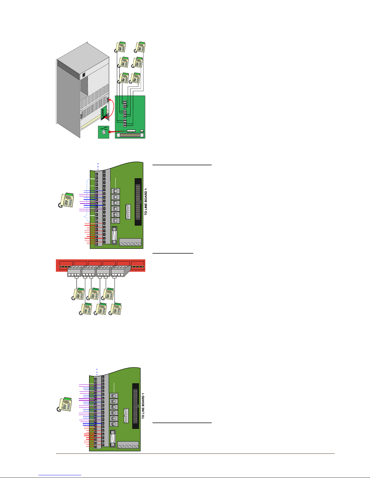
Telephones and control outputs are connected to a connection board
mounted on the server connection eld.
Telephone connection boards with transient protection (100 9930 202)
and subscriber connection cables with lter board (100 9501 031) must
be purchased separately.
Telephones may also be connected to an LCM board (100 9950 100).
This board is likely to be installed in XE servers with DTMF telephones
due to the expanded capacity. The default DIP switch settings should
normally not be changed.
The rst and last three connector pairs on each board shall not be used.
AlphaCom XE7
All telephones are connected by means of pluggable screw terminals on
the server backplane.
The ALTB board can be placed in any board position 1-6. The example
drawing shows an ATLB board in position 2. If possible, avoid using
boards in position 1 as connection points 5 and 6 are used for program
input by default.
Further information on the ATLB board is found in datasheet
A100K10237.
2.2.11 ATLB-12 - Telephone Line Board
ATLB-12 has the same functions as ATLB except that it has 12 two-wire
DTMF telephone lines. ATLB-12 does not support line monitoring.
The 6 rst telephones get the physical number according to the card’s
physical slot and the last 6 telephones have numbers with an offset of
+276 to the 6 rst physical numbers.
This board is likely to be installed in XE servers with DTMF telephones
due to the expanded capacity.
The default DIP switch settings should normally not be changed.
See separate LCM documentation for more information.
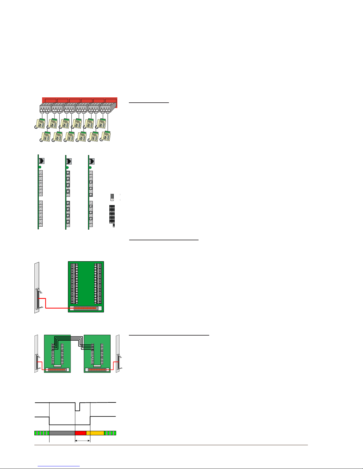
AlphaCom XE20/XE26
The ATLB-12 boards are connected to the LCM via 1.5 m (100 9501
011) or 3.0 m (100 9501 014) connection cables, one for each board.
RING1
TIP1
RING2
TIP2
RING3
TIP3
RING4
TIP4
RING5
TIP5
RING6
TIP6
G123456G
RCO
1
2
3
4
5
6
CONNECTION BOARD
TX RX G
MRBD
1....6
Relay board
1A
2A
3A
4A
5A
6A
7A
1B
2B
3B
4B
5B
6B
7B
1C
2C
3C
4C
5C
6C
7C
1D
2D
3D
4D
5D
6D
7D
1 RELAY OUTPUTS 6
1K+
1K-
2K+
2K-
3K+
3K-
4K+
4K-
5K+
5K-
6K+
6K-
S6
S5
S4
S3
S2
S1
2
4
6
3
5
1
1
RCO 6
RCO 5
RCO 3
RCO 4
RCO 2
RCO 1
Physical no.
Line board 1
24V
Poten
F
ree
127
8 9 10
11
A A A AB B B BC C C CD D D D
NC
NCNC
NC
7 9 11
8
10
12
Phys. no.
1A
2A
3A
4A
5A
6A
7A
1B
2B
3B
4B
5B
6B
7B
1C
2C
3C
4C
5C
6C
7C
1D
2D
3D
4D
5D
6D
7D
1 RELAY OUTPUTS 6
1K+
1K-
2K+
2K-
3K+
3K-
4K+
4K-
5K+
5K-
6K+
6K-
S6
S5
S4
S3
S2
S1
Poten
Free
1
5
277
279
281
2
6
278
280
282
3
4
1
RCO 6
RCO 5
RCO 3
RCO 4
RCO 2
RCO 1
Physical no.
24V
Page 16
16
A100K10805
AlphaCom XE - Installation, Conguration & Operation
Stations are connected to the terminal strip, the rst telephone on Line
Board 1 to the terminals marked 1A, B, the next to 1C, D and so on.
Telephones on Line Board 2 starts at terminal 7.
RCOs are taken from Line Board 1 and are available on terminals
marked 1K+/- to 6K+/-.
RCO function is set by the switches S1 to S6.
- Poten Free Potential-free closing contacts, max. 250 VAC, 5 A
- 24V Fused internal 24VDC, max. 1 A
Telephones may also be connected to connection boards 100 9930 202
- two connection boards are needed per ATLB-12 board.
AlphaCom XE7
All telephones are connected by means of pluggable screw terminals on
the server backplane.
The ALTB-12 board can be placed in any board positions 1-6. The
example drawing shows an ATLB-12 board in position 2. Avoid using
boards in position 1 if possible as connection points 5 and 6 are
reserved for program input by default.
2.2.12 AGA - General Purpose Audio Interface
The AGA board is a multi-purpose audio interface board used for
program feeding or speech communication between modules. There are
easily accessible potentiometers at the front for input sensitivity control
of the audio channels.
The impedance can be set to 600 ohm or ‘high’ for each input by strap
switches on the board.
Further information on the AGA board is found in datasheet
A100K10182.
Multi program distribution
Each board provides 16 audio inputs for program distribution when used
in AlphaCom XE20 or XE26. There can be 1 to 4 boards in a module
placed in positions 18 to 21.
An AGA connection kit, 100 9930 300, has to be purchased to connect
the audio sources. The kit contains a lter board, a connection board,
and an interface cable.
AGA boards can be placed in board positions 1-6 in an XE7 server but
the number of inputs are reduced to 6 per board. Input adjustments
are performed by potentiometers 4, 6, 8, 10, 12 and 14. The program
sources are connected to the c and d terminals on backplane
connectors.
Audio distribution in AlphaNet
Each board provides 6 audio channels between the servers.
There can be any number of AGA boards in each server placed in
any position. Positions 20-23 are recommended in XE26 to avoid
modications of the backplane.
Use the same lter board with cable and connection board as ASLT.
2.3 Performing a Cold Start
A cold start of the AMC-IP board will delete all previous programming,
load the default database and set the default IP address to 169.254.1.5
with mask 255.255.0.0 on Eth0. See section 3.4 for default settings.
2.3.1 Cold start procedure
● Turn the server mains switch ON (at the rear of the cabinet).
127
8 9 10
11
7
8
9
10
11
12
283
284
285
286
287
288
Phys. no.
Line 1
Line 2
Line 3
Line 4
Line 5
Line 6
Hot plug
Board status
AGA board
S1-3
S4-6
S7-9
S10-12
S13-15
S16
600 ohm
Hi imp.
AlphaNet
Line 1
Line 2
Line 3
Line 4
Line 5
Line 6
Line 7
Line 8
Hot plug
Board status
AGA board
Multi module
Prog 7 23
Prog 8 24
Prog 9 25
Prog 10 26
Prog 11 27
Prog 12 28
Prog 13 29
Prog 14 30
Prog 15 31
Prog 16 32
Prog 17 33
Prog 18 34
Prog 19 35
Prog 20 36
Prog 21 37
Prog 22 38
Hot plug
Board status
AGA board
Mulit Program
Card pos. 21 20
Strap field
1
2
3
4
5
6
7
8
1
2
3
4
5
6
7
8
1
2
3
4
5
6
7
8
9
10
11
12
13
14
15
16
9
10
11
12
13
14
15
16
9
10
11
12
13
14
15
16
Pot no.
Pot no.
Pot no.
2
4
6
8
10
12
14
16
1
3
5
7
9
11
13
15
P7/23
P9/25
P11/27
P13/29
P15/31
P17/33
P19/35
P21/37
P8/24
P10/26
P12/28
P14/30
P16/32
P18/34
P20/36
P22/38
Board pos.
21/20
Board pos.
21/20
MULTI
PROGRAM
1 1
2 2
3 3
4 4
5
5
6 6
a - c
b - d
c - a
d - b
Exchange 1 Exchange 2
>1 sec
RESET - APC
COLD START - AMC
Status LED
Page 17
17
AlphaCom XE - Installation, Conguration & Operation
A100K10805
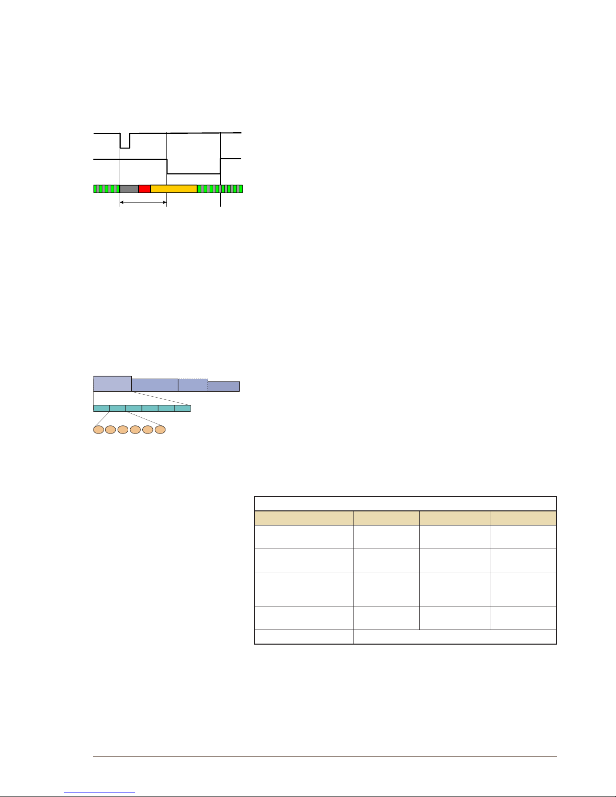
● Press and hold the cold start button on the AMC-IP board.
● Press the reset button on the APC card briey.
- XE7: the reset button is located on the power card
- XE1: Power up while keeping the cold start button pressed.
● Keep the cold start button pressed at least 1 second after reset.
- The AMC status LED will blink green when the boot is ready.
2.3.2 Cold start AMC application only (retain IP setting)
● Press the reset button on the APC card briey.
- XE7: the reset button is located on the power card
- XE1: Power up while keeping the cold start button pressed.
● After 10 seconds, press the cold start button on the AMC-IP board.
● Keep the cold start button pressed until the AMC running LED blinks
green.
2.4 Modifying Factory Default Settings
The system is set up with a default program and works without any
further programming. To change or add to the default settings, the
AlphaPro programming tool must be used - see section 5.
Perform System Backup if any default setting has been changed - see
section 12. The default parameters are restored by performing a cold
start - see section 2.3.
2.5 Default Directory and Feature Numbers
2.5.1 Station numbers
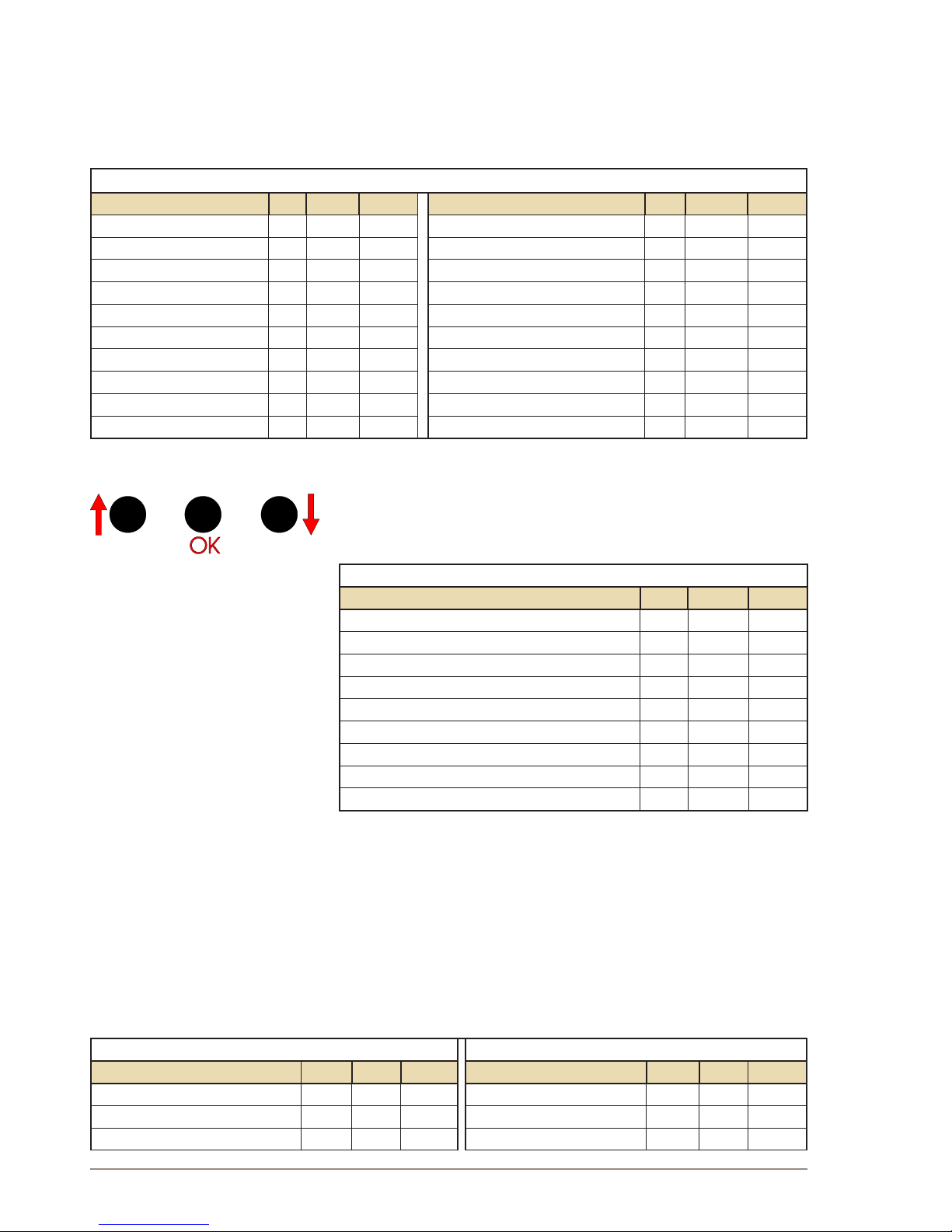
The number series 101 to 499 and 5000 to 5152 are default directory
numbers for all AlphaCom XE servers. The directory numbers are
connected to physical numbers in the range from 1 to 552, where the
physical numbers are given by the subscriber point on a board in a
certain position in a dened module.
Since the card positions 2-7 are not used in XE20, the corresponding
default subscriber numbers are missing.
The directory numbers can be changed by using the AlphaPro
programming tool.
ANALOG STATION NUMBER TABLE
AlphaCom modules XE7 XE20 XE26
Single or master
101 - 136
101 - 106
143 - 238
101 - 238
1
st
slave*
239 - 274
239 - 244
281 - 376
239 - 376
2
nd
slave*
377 - 413
377 - 382
419 - 499
5000 - 5014
377 - 499
5000 - 5014
3
rd
slave*
5015 - 5051
5015 - 5020
5057 - 5152
5015 - 5152
Display text Station 1, Station 2, etc.
2.5.2 Class of Service (CoS)
A Class of Service denes a set of features available for a station. There
are 16 freely programmable classes where three are pre-dened during
setup. All stations are normally in the CoS1 group.
CoS1: Regular stations.
CoS15: Public telephone lines (SIP trunk)
10 sec
RESET - APC
COLD START - AMC
Status LED
XE 26
138
XE 7
XE 20
1
36
80
102
1 2 3 4 5 6
ASLT board
108 109 110 111 112107
Physical number
1...6
7...12
13...18 19...24 25...30 31...36
Single /first module
Subscriber number
* Slave modules are only required for
analog stations. IP stations are always
registered to the master module.
Page 18
18
A100K10805
AlphaCom XE - Installation, Conguration & Operation
CoS16: Includes all features by default, dedicated to Super User on
physical number 1.
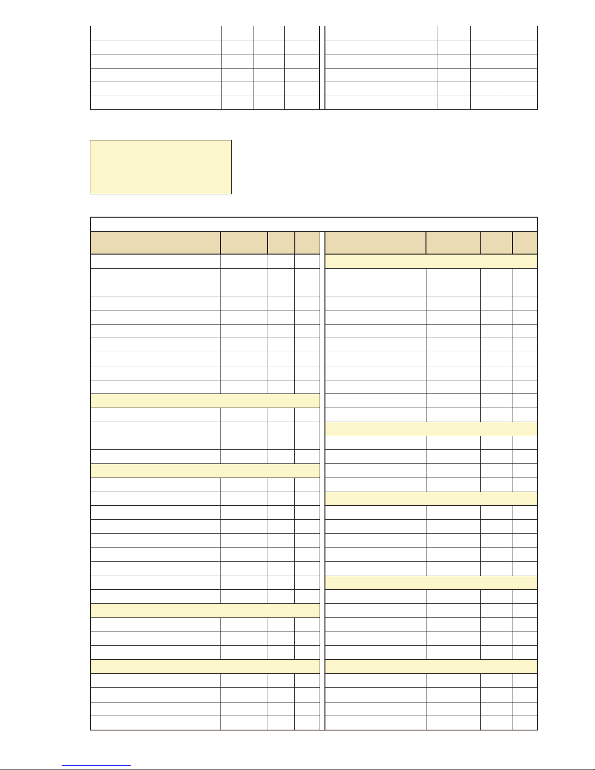
2.5.3 Features during connection
A number of features can be utilized during conversation and each of
these have their own code number.
CODES DURING CONVERSATION
Feature No. CoS1 CoS15 Feature No. CoS1 CoS15
Microphone mute
0 X
Read own message remotely
51 X X
Step directory menu
0 X
Call Back message to own station
55 X
Repeat absence message
1 X X
Include in Open Duplex Conference
56 X
Inquiry Call / Broker
2 X X
Busy Notify
57 X X
Call Transfer
3 X
Busy Override
58
Pocket Pager default, no text
44 X
Private and Absence Override
59
Pocket Paging with answer
45 X X
Remote Control (Door opening)
6 X
Pocket Paging, text message
46 X X
Send standard voice message
7 X X
Pocket Paging, voice message
47 X X
Call Back
8 X
Change message remotely
50 X X
Search
9 X X
2.5.4 Voice and display messages
When the station is idle, entering a digit/number code will show different menus
on the station display. Navigation in the menus is done using the 7, 8, and 9
keys.
DISPLAY MENUS
Feature No. CoS1 CoS15
Info Service 60 X
Group Call menu 610 X
Absent menu 611 X
Message menu 612 X
Audio Program menu 613 X
Name directory 614 X
Features menu 615 X
Service menu 616 X
Conference menu 618 X
After a cold start Info Service (60) is available on DAK 9 and Person
Directory (614) is available on DAK 10.
Messages are given as a text string in the display. A spoken message is
given if the voice module ASVP is installed.
Leave pre-recorded standard messages by dialing the extension number
+ 7 + message code. Listen to and reset message by code number 70.
Absence messages are left in your own idle station by dialing the
message code number. Add digits for date or time if prompted.
STANDARD MESSAGES (VOICE/DISPLAY) ABSENCE MESSAGES (VOICE/DISPLAY)
Feature No. CoS1 CoS15 Feature No. CoS1 CoS15
Contact switchboard 660 X Out 771 X
Call phone number 661 X Meeting 772 X
Call home 663 X Gone for the day 773 X
7 8 9
Page 19
19
AlphaCom XE - Installation, Conguration & Operation
A100K10805
Call your spouse 664 X Absent today 774 X
Call me back 666 X Busy 775 X
Remember meeting 667 X Lunch 776 X
Fax waiting 668 X On holiday 777 X
Delivery to you 669 X Away 778 X
Not available 779 X
2.5.5 Station functions
A number of features can be initiated from an idle station by dialing
a default feature number. Some of these actions require a target
subscriber number after the feature number.
It is recommended to program the most used features to single-touch
keys for easy access.
FUNCTIONS FROM IDLE STATION
Feature No.
CoS 1CoS
15
Feature No.
CoS 1CoS
15
Delete message, clear station
70 X X GROUP CALL
Call Forward
71 X
All Call (all subscribers)
84 X X
Follow Me
72 X
Group Call 2-5 (empty)
85-88 X X
Remote station reset
73 X
Group Call 6-15 (empty)
890-899 X X
Program single-touch key
784 X
Recall to group 1-5 (84-88)
9084-9088
Activate RCO in own station
9531 X
Recall to global group 1
9101
Re-dial
9532 X
Recall to any group
765
Wake-up call
7883 X
Answer Group Call
99 X X
Set station in OPEN
7886 X
Group Call lter
7931-7933
Set station in PRIVATE
7887 X
Group Call lter OFF
7930
CALL REQUEST
Disconnect Group Call
7884
Call Request to CRM stations
621 X
Ringing Group
6701-6710 X X
Call Request, alarm
622 X CONFERENCE
Call Request, ordinary
623 X
Simplex Conference 1-50
8201-8250 X
Call Request, transfer
7870 X
Simplex Conference OFF
8200 X
PROGRAM DISTRIBUTION
Duplex Conference 1-20
8301-8320 X
Program 1-6
801-806* X
Duplex Conference OFF
8300 X
Program 7-70
*** X ALARM
Next program (step up)
790** X
Stored Voice Message
8181-8182
Previous program (step down)
791 X Mess. 1 to loc. group 1 9184
Program on/off (toggle)
792 X
Alarm messages
8191-8199
Program / conf. to person
74 X
Alarm message OFF
8190
Program / conf. to group
75
Alarm message to group
761 or 765
Program / conf. to person on/off
762 X MULTI CONFERENCE STATION
Program OFF
800 or C X
MCS Activate
7980
PAGING
MCS Priority
7981
Answer Paging (without display)
96 X X
MCS Select
7982
Answer Paging 1-4 (with display)
980-983 X X
MCS Talk-Back
7983
Direct Paging
9700 X X
MCS Deactivate all
7984
EVENTS
AUDIO MESSAGING
User Event with tone
9 533 X
Recording from station
8180 X
User Event silent
9534 X
Stored Voice message
8181-8182 X
Two-step Event trigger
9535 X
PA activation, multi-step
765 X
Digit Event trigger
9545 X
PA activation, one-step
9084-9088 X
The Multi Conference Station (MCS) is
no longer produced. The special feature
numbers for this station is maintained
for the sake of backwards compatibility.
Page 20
20
A100K10805
AlphaCom XE - Installation, Conguration & Operation
PA to global group
9101 X
Recorded message to group 1
9184 X
Auto-attendant
9550 X
* 805-806 in XE7
** Default is 6 programs + OFF
*** Not in Auto-load
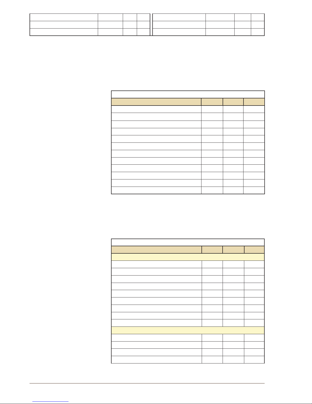
2.5.6 System maintenance
System maintenance access is restricted to the Super User station
connected to physical line number 1. This station has Class of Service
16, All Functions.
FEATURES FOR SUPER USER STATION
Feature No. CoS1 CoS15
Set volume 783
Set time and date 785
Station ID (directory + physical nos.) 789 X
AlphaCom IP conguration 7810
Install backup from EPROM 7819
Store backup to EPROM 7820
Reset board error 7871
AGA audio test 7872
Set access to feature 7873
Tone test 7885
Block alarm input 7888
Unblock alarm input 7889
2.5.7 Control room stations
Stations used for control rooms such as guard locations in prisons,
buildings, parking facilities, etc. may be a dedicated Control Room
Master (CRM) station or a normal master station with display.
CONTROL ROOM STATION FEATURES
Feature No. CoS1 CoS15
CONTROL ROOM STATIONS
Call Request, Alarm 622 X
Call Request, Ordinary 623 X
Call Request, Alarm 624 X
Call Request, Ordinary 625 X
Cancel Call Request 626 X
Call request, Alarm 627 X
Call Request, Ordinary 628 X
Call Request transfer 7870 X
Acknowledge Priority Mail 7882
MLH/CRM STATIONS ONLY
Call request 621 X
CRM ID 786
Lamp Test 7874
Lamp Test all 7875
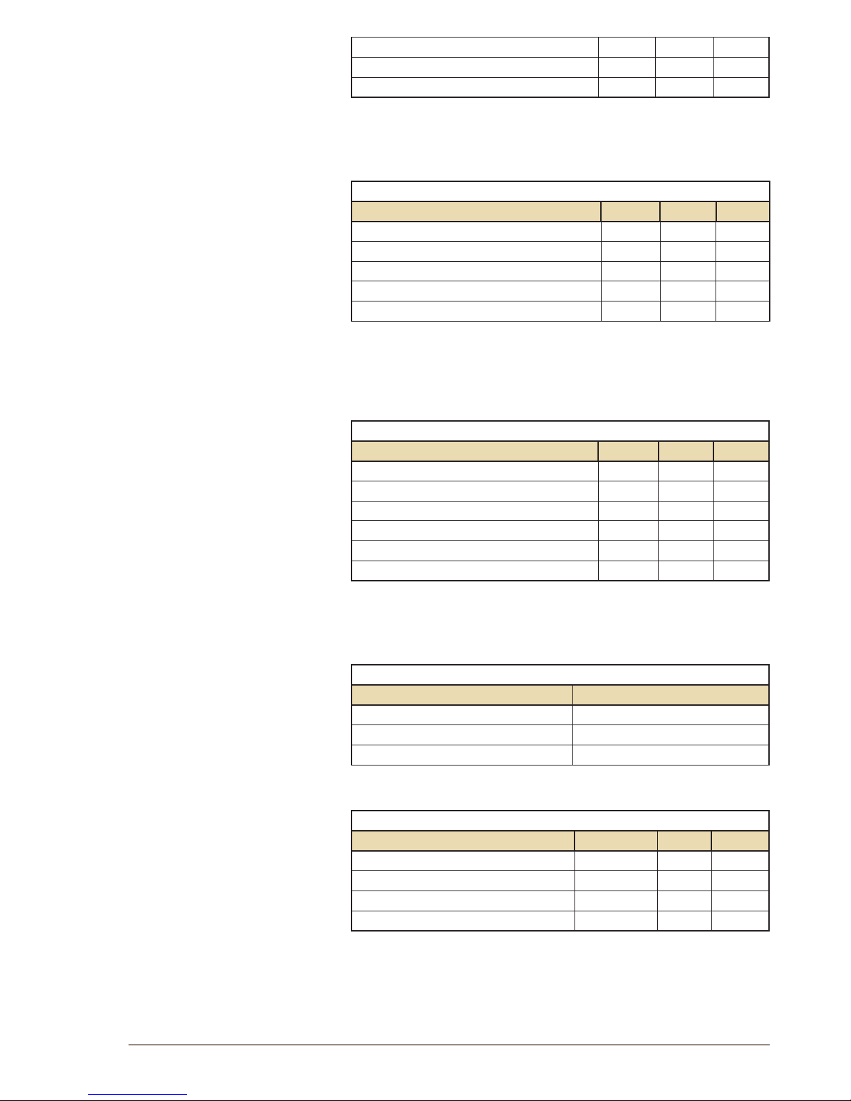
Page 21
21
AlphaCom XE - Installation, Conguration & Operation
A100K10805
Output time 7876
Reset this CRM/MLH station 7877
Reset all CRM/MLH stations 7878 X
2.5.8 Mail queue navigation
A mail message can be sent to any dened display station. The mail can
contain a message about call request, technical alarms, and errors.
MAIL QUEUE
Feature No. CoS1 CoS15
Delete mail without answering 7630 X X
Last mail in queue 7633 X X
Previous mail in queue 7637 X X
Call to sender of mail 7638 X X
Next mail in queue 7639 X X
2.5.9 Dual Display station
The introduction of master stations with dual display where the second
display can be programmed with DAK key names has lead to a series of
specic feature codes.
DUAL DISPLAY FEATURES
Feature No. CoS1 CoS15
Alphanumeric search 9537 X
Edit DAK text 9540 X
Program DAK 9541 X
Dual Display menu 9542 X
Dual Display DAK page down 9543 X
Dual Display DAK page up 9544 X
2.5.10 Telephone functions
When calling an intercom station from an external telephone, the M-key
(Simplex) can be simulated by the * and # keys on the telephone.
USING TELEPHONES (SIP trunk)
Telephone function Intercom function.
External call 0
* key from telephone M-key on
# key from telephone M-key released
2.5.11 AlphaNet
NETWORK FEATURES
Feature No. CoS1 CoS15
Prex Exchange 1 54 X X
Prex Exchange 2 55 X X
Global Group Call 1-10 9001-9010 X X
Build Global Group 7879
Page 22
22
A100K10805
AlphaCom XE - Installation, Conguration & Operation
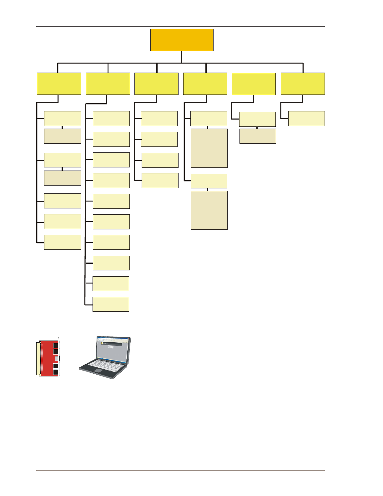
3 AlphaWeb XE
3.1 Connecting to AlphaCom using AlphaWeb
● Connect the PC Ethernet port to the LAN port (Eth0) on the AMC-IP
lter card.
● Open your web browser to access AlphaWeb.
L The factory default IP address of the AlphaCom server is
169.254.1.5. In order for your PC to communicate with the server, it
is necessary to change its Internet Protocol Properties to use an IP
address that is in the same range as 169.254.1.5.
● Enter http://169.254.1.5 in the address eld
- Connection with the AMC is veried by the text:
[Login] Secure AlphaWeb (https)
[Login] Unsecure AlphaWeb (http)
● Click Login for Unsecure AlphaWeb (http)
- unless encrypted access to internet is required for safety reasons.
If [Login] Secure AlphaWeb is not shown, https may be activated in
AlphaWeb by selecting Filters in the SystemConguration menu (see
section 3.4.4).
AlphaWeb XE
Interfaces
Routers
IP Station
Upgrade
Licensing
Filters
Stations
User
Management
Logging
Time and Date
Host Names
Messaging
System
Configuration
System
Upgrade
Custom
Scripts
System
Recovery
M100
Config.
Backup
System
Maintenance
RingMaster
External
Systems
About
Help
System
Monitoring
Node
Information
- Infromation
- Processes
- Scripts
- Security
- General
- Trunks
- Call numbers
- Global groups
- Privacy links
- Call Request
groups
- General
- Group Call map
- Module/
Serial port
- AGA-LUS map
- Ringing group
- Configured
- Unconfigured
AlphaNet
Audio
Statistics
Stations
Logging
Custom
Scripts
Eth0
FILTER BOARD
0
0
1
1
AlphaWeb XE is an embedded web server running on AlphaCom
XE. It allows the users to log in using a standard web browser
such as Internet Explorer or Firefox to operate and manage the
AlphaCom XE system.
The AlphaWeb server provides functions for system monitoring,
system conguration, and system upgrade.
Page 23
23
AlphaCom XE - Installation, Conguration & Operation
A100K10805
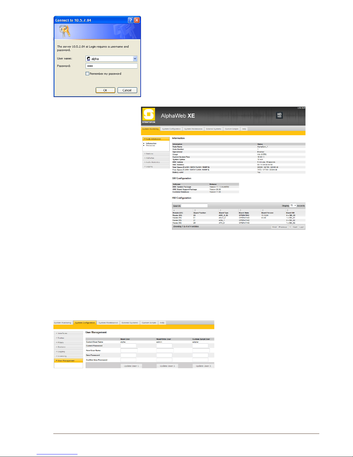
● The user will be prompted for a user name and password. To log in
as a user with reading rights only, do as follows:
Default user name: alpha
Default password: com
● To be able to change the conguration, the user must log in as an
administrator. The default login will then be:
User name: admin
Password: alphaadmin
A window with server conguration information will be displayed:
3.1.1 Saving and applying changes
When new conguration parameters are entered, they should be saved
to the conguration le by clicking Save.
The conguration data is then only saved to the AlphaCom conguration
le and not applied to the running conguration. To get the new
conguration data applied to the running conguration, click Apply.
3.2 Changing Default User Name and Password
It is recommended to change the default user names and passwords for
security reasons.
● Select SystemConguration>
User Management
● Enter the old passwords for both
Read access and Read/Write access
(defaults: com and alphaadmin)
● Enter new user names and
passwords
● Re-enter the new passwords to conrm
● Verify by clicking Update User 1 and Update User 2
● Write down the selected passwords and keep them in a secure
place.
Page 24
24
A100K10805
AlphaCom XE - Installation, Conguration & Operation
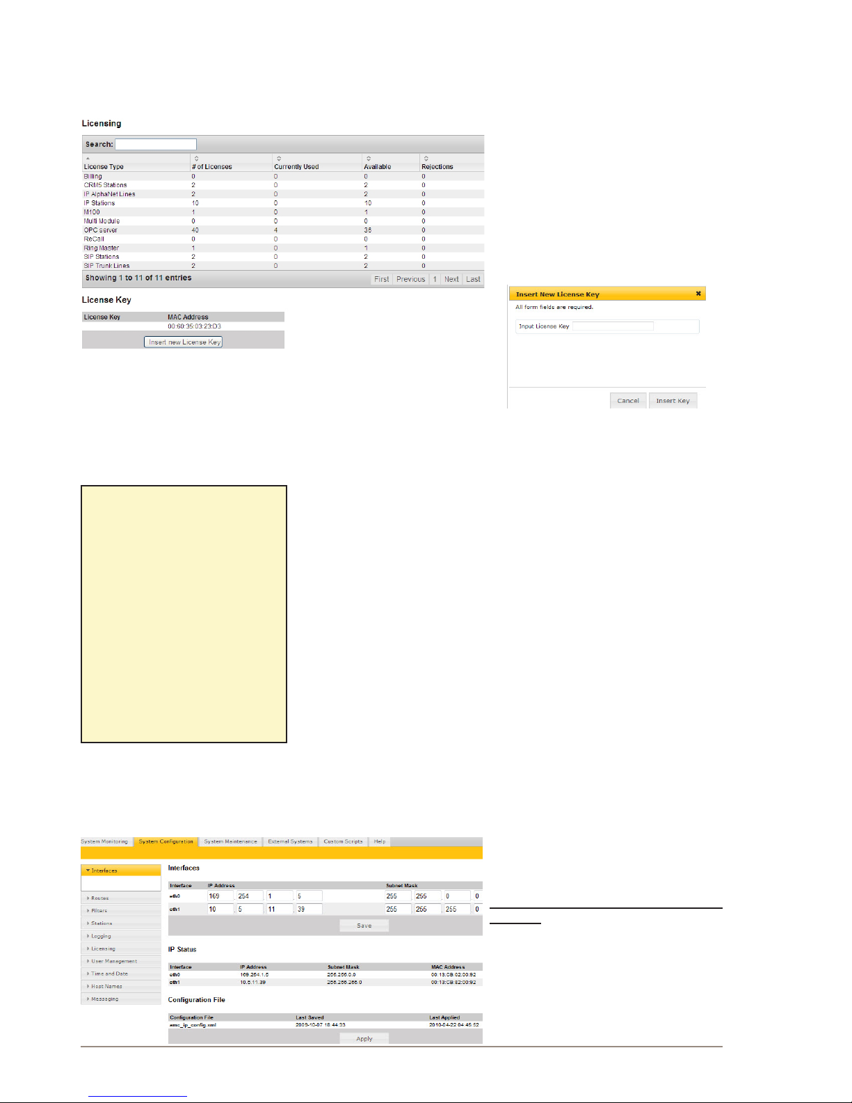
3.3 Installing License Keys
To use AlphaCom features such as VoIP, AlphaNet, and SIP, the system
requires software license keys. This license key is valid for one MAC
address. Obtain the license key for the feature from your AlphaCom
distributor.
To install the license:
● Select SystemConguration>
Licensing
● Click Insert new License Key
● Enter the key string in the Input
License Key eld
● Click Insert Key to install the
license.
3.4 IPConguration
3.4.1 Overview
An IP address (Internet Protocol address) is a unique number that
devices use in order to identify and communicate with each other on a
network utilizing the Internet Protocol standard. An IP address consists
of 32 bits. They are commonly expressed as a dotted quad, four octets
(8 bits) separated by periods.
IP addresses are divided into two parts:
● Network address
- identies a whole network or subnet
● Host address
- identies a particular device’s connection or interface to that
network
This division is used to control how trafc is routed in and among
IP networks. It is the Subnet Mask that decides which part of the IP
address is the Subnet number and which part is the Host number.
3.4.2 IP interfaces
To connect the AlphaCom XE to your IP network, you need to enter
the IP settings for the Ethernet ports and IP route entries according
to network. You should obtain IP
addresses and IP routes from your IT
network administrator.
Set the IP address for Ethernet port 0
and/or 1
● Log in to AlphaCom via AlphaWeb
● Select SystemConguration>
Interfaces
● Enter the IP Address
● Enter the Subnet Mask
Example:
IP address: 10.1.5.48
Subnet Mask: 255.255.255.0
The Subnet Mask shows that
the device with the address
10.1.5.48 belongs to subnet
10.1.5.0 and has host number
48.
If the mask is changed to
255.255.0.0, the device with
the address 10.1.5.48 will
belong to the subnet 10.1.0.0
and have host number 5.48.
Page 25
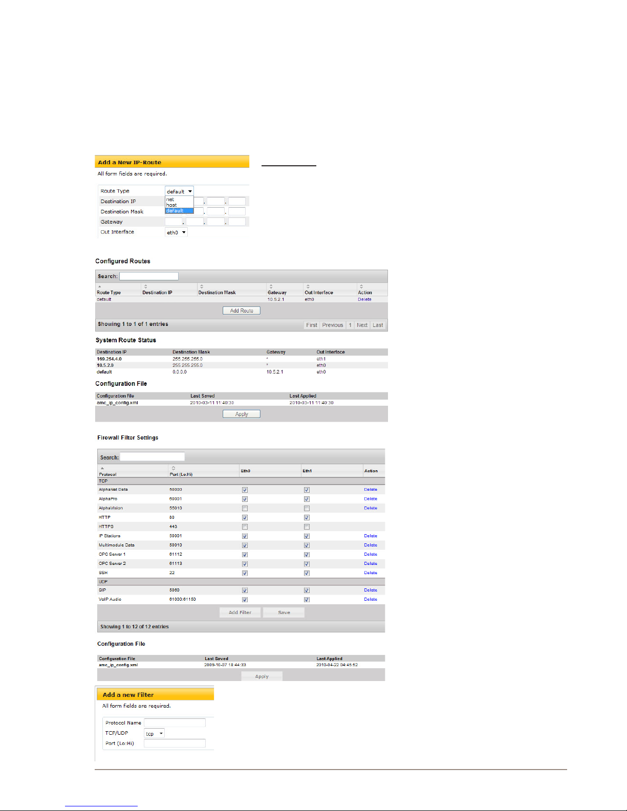
25
AlphaCom XE - Installation, Conguration & Operation
A100K10805
● Click Save to save the values
L Do NOT click Apply until all address, routing and lter changes as
described in sections 3.4.2, 3.4.3 and 3.4.4 have been saved!
3.4.3 CongureIProuting
The IP Routing table of AlphaCom must be congured if there is a
need to communicate with a device outside its own subnet. A “device”
could be another AlphaCom, a PC (AlphaPro, AlphaWeb, SysLog), SIP
gateway, etc. If AlphaCom and the device belong to the same subnet,
there is no need to specify any routing information.
Route types
Route type Host is used to set up a route to a single device outside the
subnet of AlphaCom.
Route type Net is used to set up a route to another network.
Route type Default is used to set up a general route to any device
outside the subnet of AlphaCom.
● Select SystemConguration>
Routes
● Select the type of IP route by clicking
Add Route
- Default IP route
Enter only Gateway (IP address) and
Out Interface Ethernet port (eth0/1)
- Network route
Enter Destination IP address,
Destination Mask, Gateway and Out
Interface Ethernet port (eth0/1)
- Host route
Enter Destination IP address, Gateway
and Out Interface Ethernet port (eth0/1)
3.4.4 Internalrewall
AlphaCom XE has an internal rewall
allowing the network administrator to
open and close IP services that accesses
the AlphaCom XE from the different
networks. By default, the AlphaCom XE
comes with the most restrictive rewall
settings.
● Select SystemConguration>
Filters
● Select the protocols that should be
allowed for each Ethernet port by
clicking the relevant checkboxes
Eth0 and Eth1
● If you want other protocols to be
allowed, click Add Filter to add a
new protocol to the lter table:
- Enter the Protocol Name
- Select protocol type - TCP/UDP
- Enter the port number - Port (Lo:Hi)
● Click Apply when all addresses,
routing and lter changes as
described in sections 3.4.2, 3.4.3
and 3.4.4 have been saved!
AlphaCom XE should now be connected to your IP network.
Page 26

26
A100K10805
AlphaCom XE - Installation, Conguration & Operation
4 AlphaPro
4.1 Overview
AlphaPro 11 is the tool for conguring the AlphaCom XE system. It
is self-contained, and simple to install and use. When a new server/
exchange shall be congured, it is given a working default factory
setting (see tables in section 2.5). The operator can modify the settings
such as:
● Directory information
● Groups
● Interfaces to CCTV, PA, paging, DECT
● AlphaNet
● Other custom behavior
There are currently over 100 dened features which can be
programmed with AlphaPro 11.
AlphaPro 11 is an off-line tool. This means that it is possible to enter all
parameters without being connected to the server/exchange. Once all
parameters are entered, AlphaPro 11 can be connected to the server/
exchange and the parameters can be sent. AlphaPro 11 can also upload
conguration information from a server/exchange.
AlphaPro 11 connects to a server/exchange via the IP network or a local
RS232 interface.
4.1.1 AlphaPro versions
AlphaPro 11 comes in two versions. A hardware dongle is used to
differentiate between the versions.
There are two types of hardware keys, one for parallel port and one for
USB port.
The versions of AlphaPro are:
● AlphaPro M
- Runs without a hardware key.
It gives access to all features (except AlphaNet), and is only for 36
subscribers.
● AlphaPro Professional
- Uses the Professional hardware key.
It gives access to all features. This version must be used when
extensive changes to the default Auto-load is made.
4.1.2 Backwards compatibility
AlphaPro version 11 supports:
● AlphaCom E, AMC-IP version 10.xx
● AlphaCom AMC version 9.x
L Older AlphaCom systems can easily be upgraded to
AlphaCom XE.
AlphaPro 11 supports uploading and conversion of an AMC version 9
conguration database to an AMC-IP conguration database.
Page 27
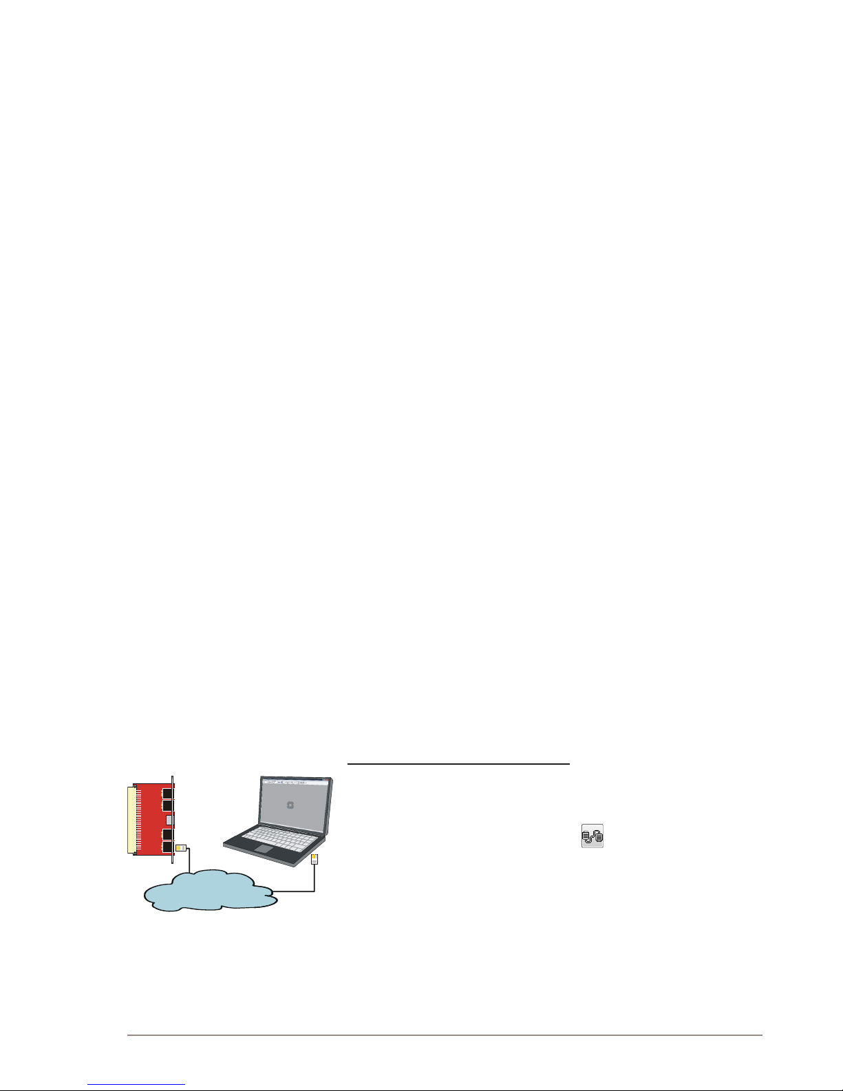
27
AlphaCom XE - Installation, Conguration & Operation
A100K10805
4.1.3 PC requirements
● Windows 2000, Windows XP
● 800 MHz or higher processor clock speed
● 256 MB of RAM or more
● 40 MB free space on the hard disk for the AlphaPro program
● 5 MB free space on the hard disk for each server to be programmed
● 1 free parallel or USB port for Hardware Key
● XGA (1024x768) or higher resolution video adapter and monitor
● Network card
● CD or DVD drive
● Optional: 1 free RS-232 port for communication if connecting to
AlphaCom AMC version 9
4.2 Getting Started with AlphaPro
4.2.1 PC setup
● Download AlphaPro 11 from www.zenitel.com or insert the CD-ROM
with the AlphaPro 11 installation.
L The instructions are based on AlphaPro 11 version. Other
versions may have slightly different images and/or procedures.
● Select and run the le installalphapro.exe
● Follow the instructions on the screen
- You can safely answer “YES” to all questions
4.2.2 Insert the HW dongle
● Insert the hardware dongle in the PC’s parallel or USB port
depending on the dongle type
● Leave the dongle in the PC during programming and transferring of
data to the server.
If the dongle is not inserted, the AlphaPro will run in AlphaPro M mode.
You will still have access to all functions (except AlphaNet), but only for
36 subscribers.
4.2.3 Connect a PC to the server
AlphaCom XE - Ethernet connection
AlphaCom XE servers communicate with AlphaPro on the PC over
the IP network. Eth0 is the default management port unless the
conguration has been changed.
When the AlphaPro communication icon is clicked, you will be
prompted for user name and password to log into AlphaCom.
- In AlphaCom XE20 and XE26, the Eth0 port is the lower RJ
connector on the AMC-IP lter board.
- In AlphaCom XE7, the Eth0 port is the left-most RJ connector on
the backplane.
- In AlphaCom XE1, the Eth0 port is the left-most RJ connector at the
rear.
Eth0
FILTER BOARD
1
0
LAN
Page 28
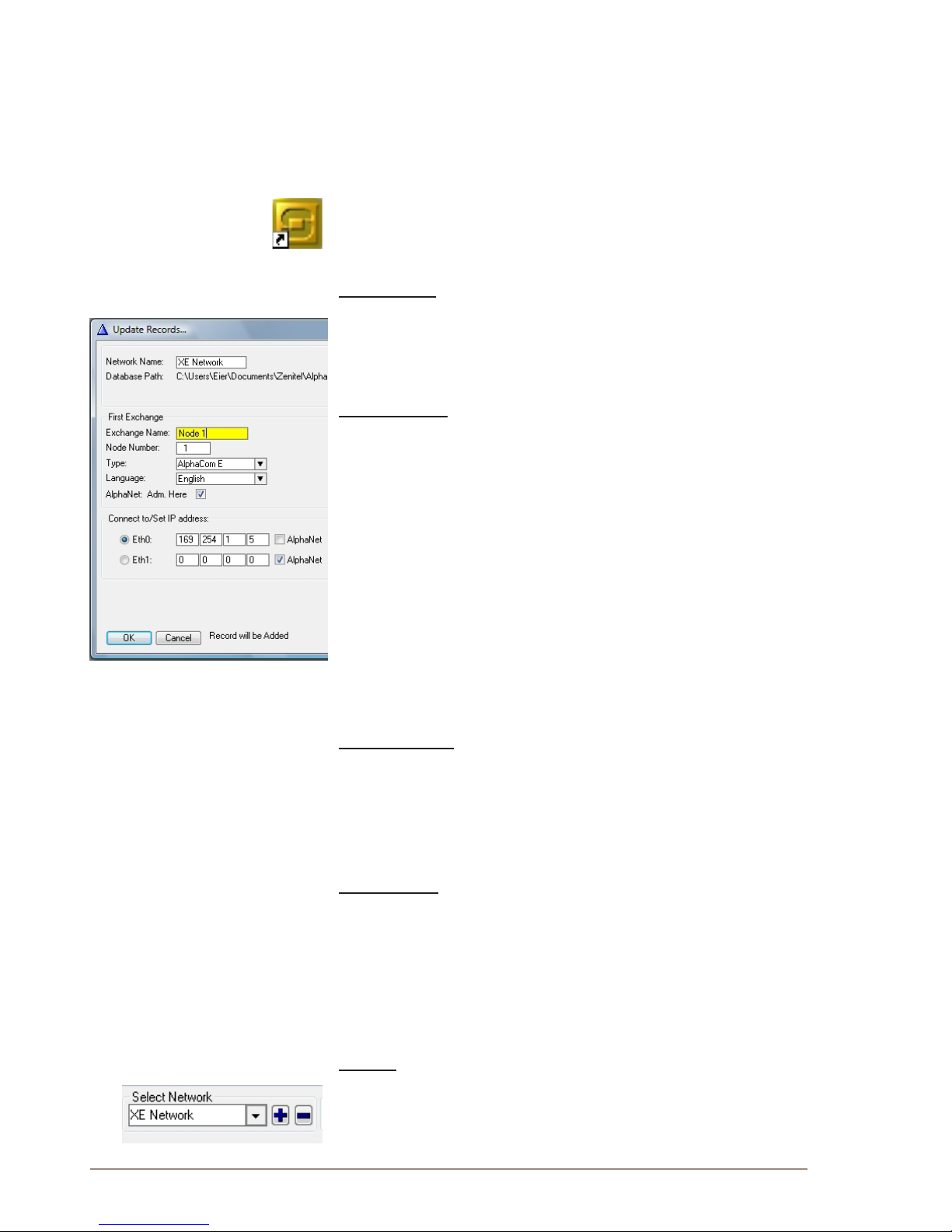
28
A100K10805
AlphaCom XE - Installation, Conguration & Operation
4.3 DeningNetworkandExchange
If you are going to program the server/exchange for the rst time, make
sure that the AlphaCom system has been cold-started (see section
2.3). The default programming tables will then be loaded. The Auto-load
values are found in section 2.5.
4.3.1 Initial programming
● Open AlphaPro by clicking on the S-icon on the PC’s desktop.
● When AlphaPro starts for the rst time, you will be asked to make an
AlphaPro database by creating a network and adding the exchange
that is part of the network.
Enter network
● Enter a system name related to customer or network.
- maximum 23 characters
- don’t use national characters like æ, ø, å, ä, é, etc.
It is possible to create more networks later on from the main window.
Enter exchange
● Enter the rst node (exchange) name
- maximum 16 characters.
● The rst exchange node number is 1
● Select the desired type of node (exchange type)
- AlphaCom E is default.
● Select the display language for the stations in the exchange.
- Available languages are: Danish, Dutch, English, Finnish, French,
German, Hebrew, Norwegian, Spanish, and Swedish.
English is the default.
● Checkbox for AlphaNet: Adm. Here
-- Creates an exchange with full database, which can be
congured from this PC.
-- Creates an exchange without database which can be pointed to
in AlphaNet routing.
Enter IP address
● Normally Eth0 is used for connection to the exchange.
● Leave the lled-in default IP address.
- If the system is part of an AlphaNet, it will be connected to Eth1. If
this IP address is unknown at this moment, it can be lled in later.
● Click OK to proceed to the AlphaPro main window.
Then you can:
● Select the exchange you are going to program
● Add networks and nodes
● Set up data communication with the exchange
● Go to the different programming windows
4.3.2 Add network or exchange
Network
● In the main window, select [+] next to the Select Network pull-down
menu
● Proceed as explained in 4.3.1
Page 29
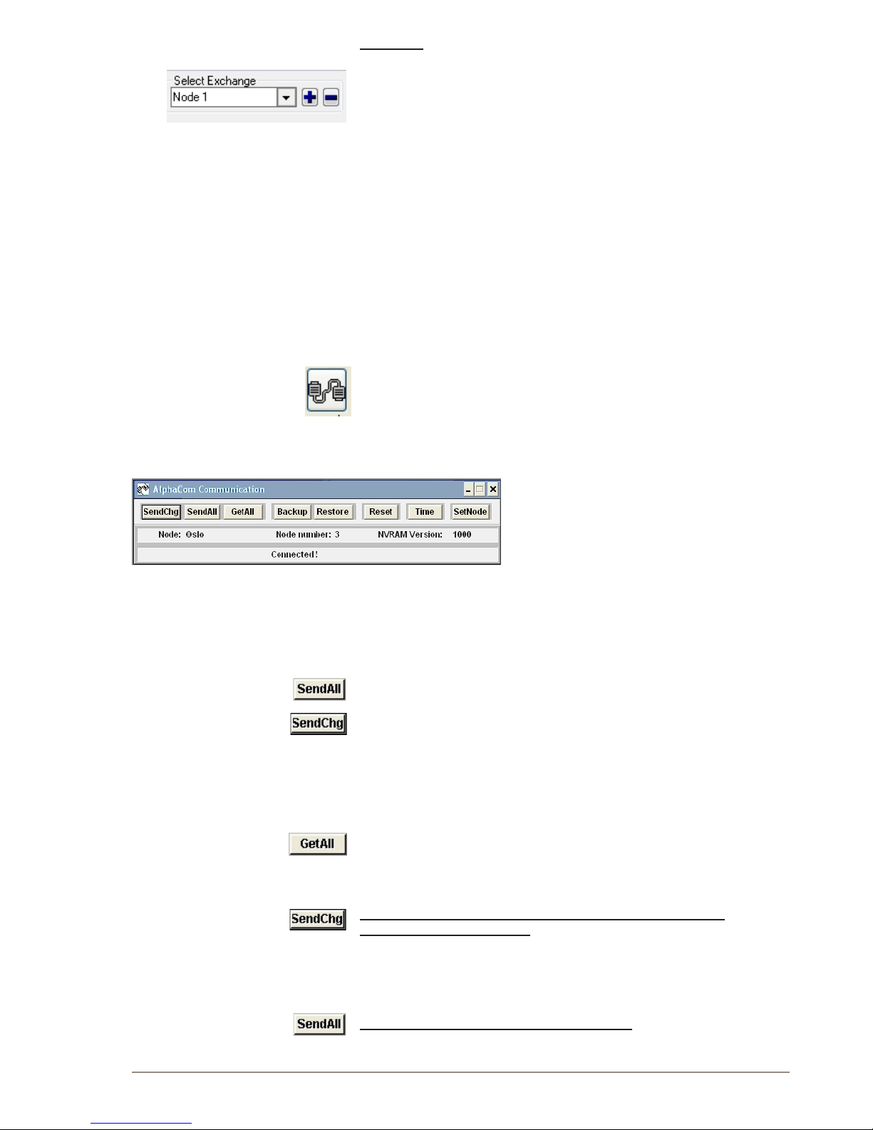
29
AlphaCom XE - Installation, Conguration & Operation
A100K10805
Exchange
● In the main window, select [+] next to the Select Exchange pull-
down menu
● Proceed as explained in 4.3.1
- The Node Number applies to AlphaNet nodes
● If this exchange is part of an AlphaNet, select Eth1 and enter the IP
address.
4.4 Data Communication
In order to establish communication between the PC and the exchange,
the communication program must be started.
L During data transfer to the AlphaCom, it is not possible to
modify conguration data in the AlphaCom.
4.4.1 Establishing data communication
● Select the exchange in the Main Window
● Click on the Communication icon
● The program will ask you for user name (default: admin) and
password (default: alphaadmin)
- The Communication window appears
- The connection is conrmed when the communication is
established and the buttons become active.
L If the PC is not connected to the exchange, a fault warning will
pop up. You may skip the data transfer until data changes have
been carried out off-line.
4.4.2 Send information to the exchange
● Click SendAll to send all data
● Click SendChg to send changed data only
- An icon in the lower right corner ashes during transmission.
● The transmission may be stopped by clicking Cancel
- The Cancel key changes to OK when the transmission is
completed. Click OK.
4.4.3 Get information from the exchange
● Click GetAll to get all data from the exchange
4.5 Communication Window Actions
Send changed data from the PC to the exchange or to all
exchanges in an AlphaNet.
● It may take about 60 seconds after the data has been sent for
changes to take effect for an exchange in normal operation.
● Some changes will require a reset for the changes to take effect.
Send all data from the PC to the exchange.
● Use this option after major conguration changes or to be sure that
Page 30
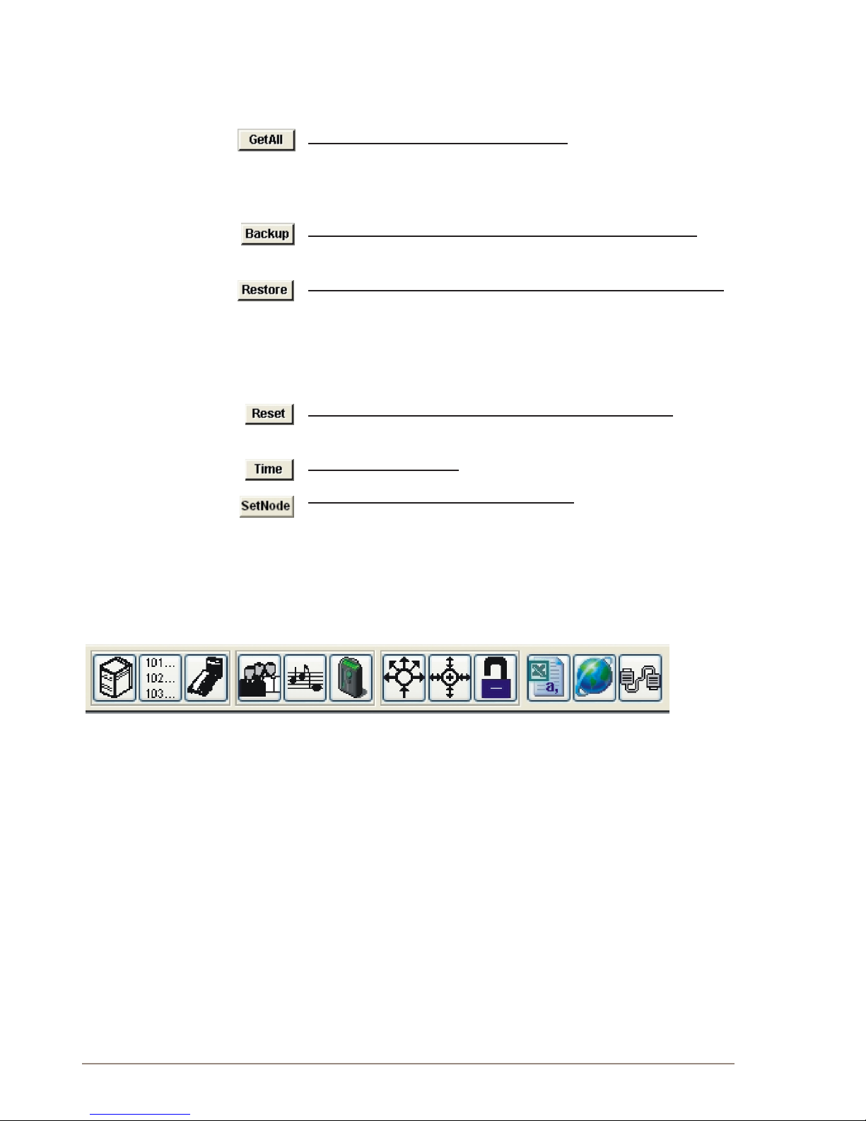
30
A100K10805
AlphaCom XE - Installation, Conguration & Operation
the database is identical to the exchange tables in NVRAM.
L Do NOT do a SendAll to an exchange in normal operation!
● Perform an exchange reset after SendAll.
Get all data from the exchange to the PC.
● The data can be stored in the current database or in a new autoloaded database.
● The conguration may be changed afterwards.
Read data from the exchange NVRAM and store it in a PC le.
● This le can not be changed by AlphaPro as it is just a backup.
Send data from a PC backup le into the NVRAM in the exchange.
● The NVRAM version that created the backup must be identical to the
NVRAM version in the exchange.
- If they are different, trust the database information and do a
SendAll.
● Always do a reset of the exchange after Restore.
Restart the exchange without changing the programming.
● The exchange will halt and all activities will be affected.
Set the exchange clock.
Modify the node number in the exchange.
● If the node number in the exchange is not the same as the node
number in the AlphaPro database, the login will fail. This command
allows you to modify the node number in the exchange.
● After Autoload, the exchange will have node no. 1. In a network of
exchanges (AlphaNet), each exchange must have its unique number.
4.6 AlphaPro Menu Structure
Exchange
& System
Directory &
Features
Audio
programs
Pocket
pagers
Simplex
Conferances
Open Duplex
Conferances
Class of
Service
Reports
AlphaWeb
Connection
Communication
Users &
Stations
Groups
Use the menus in AlphaPro to change the default system setup. The
menu bar at the top of the screen has 12 main menus accessed by
clicking on its icon. Each main menu will have one or more selectable
tabs or submenus.
AlphaPro may be run without being connected to AlphaCom (off-line),
and all changes can be saved to the PC and copied to the system later
on.
It is good practice to start the programming in the Exchange & System
menu and continue rightwards on the menu bar.
The menu structure for AlphaPro Professional is shown in the following
gures.
L The menu structure in this section is based on AlphaPro 11.
Other versions may differ slightly.
Page 31
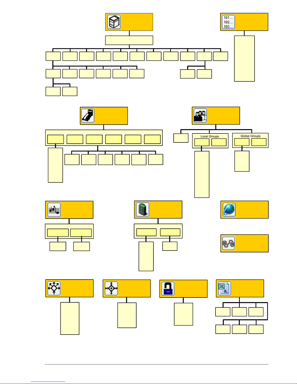
31
AlphaCom XE - Installation, Conguration & Operation
A100K10805
AlphaWeb
Connection
General
settings
Sequences
Name
Audio
Programs
Audio programs
Communication
CoS
Number
Description
Valied
features
Class of
Service
Number
Description
Master
Setup
priority
Open Duplex
Conferences
System
Inputs
General
UDP text
Faults
Calls and
options
Remote
Control
Net
Routing
Ping
Logs and
errors
Remote
Control
Timers
Serial
ports
Fire
alarm
Boards
VoIP
Event
actions
External
devices
Net
Audio
Node
Cluster
Node
Exchange
& System
Exchange information
PC settings
Gong
tones
Members
Members
Groups
Name
Access
level
Priority
General
Directory
Numbers
Directory
numbers
Display text
Feature
description
CoS
restrictions
Hide info in
idle
Visibility
Timings
General
settings
Pager
settings
Number
Name
Driver
Type
Receiver
number
Pocket
Pagers
Pocket Pagers
Global
Groups
Net
Routing
Group
Members
Net
Audio
Groups
Users
Reports
Group
User
preferences
Event
actions
Automatic
search
DAK
program-
ming
Line
monitoring
Excluded
from
group
User
defined
Phone
Station
type
Station / User
Users
Number
Display
text
Station
type
Volume
Group
General
Number
Description
Default
member
Default
speaker
Talk priority
Simplex
Conferences
Pager
General
Name
Number
Tex t
Access
level
Priority
Gong
type
Missing
members
Audio program
settings
Page 32
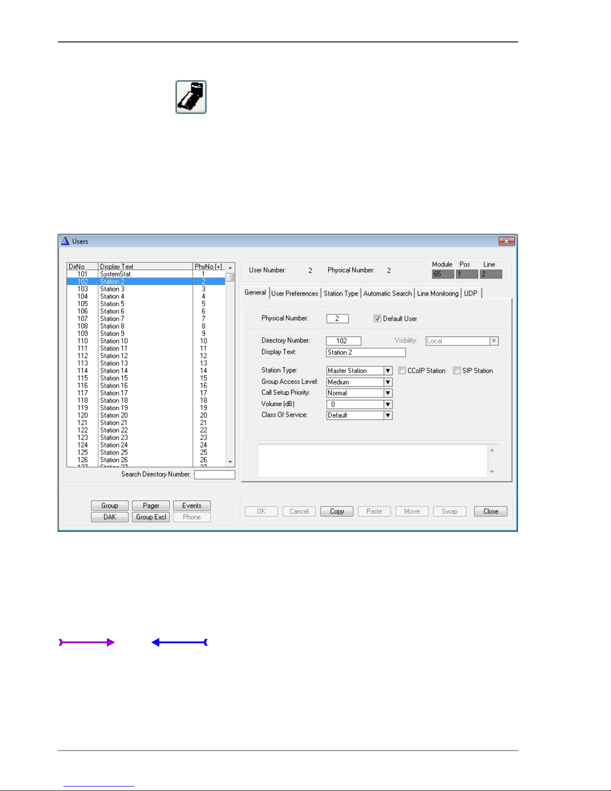
32
A100K10805
AlphaCom XE - Installation, Conguration & Operation
5 StationConguration
5.1 CongurationinAlphaPro
Conguration of stations and users are undertaken in the Users &
Stations section of AlphaPro.
Conguration of stations are done by lling in the elds under Users &
Stations.
The main elds for a normal conguration are:
- Physical Number
- Directory Number
- Display Text
- Station Type
- Visibility
To congure stations, click the Users & Stations icon.
All stations are identied by the exchange with its physical number.
The physical number for a star-wired station is the number of the
physical wire connection point on the ASLT or ATLB card.
IP stations must also be given physical numbers to follow the same
logic. This number can be any number below 552, but must not overlap
star-wired station physical numbers.
L Start numbering the IP stations from 552 and downwards to avoid occupied
number problems if the exchange is extended with more star-wired stations
later on.
● Directory Number is the number to dial to reach the station.
- The default number can be changed to any 2-8 digit number
starting with 1, 2, 3, 4 or 5. Numbers with rst digit 6-9 are reserved
for functions. If these numbers should be used, the corresponding
function code must be changed. (See section 2.5.1.)
● Display Text is the station ID text shown in the called station’s
display.
1, 2, 3, 4, 5, ...... 550, 551, 552
Physical numbers
Star wired stations
IP stations
Page 33
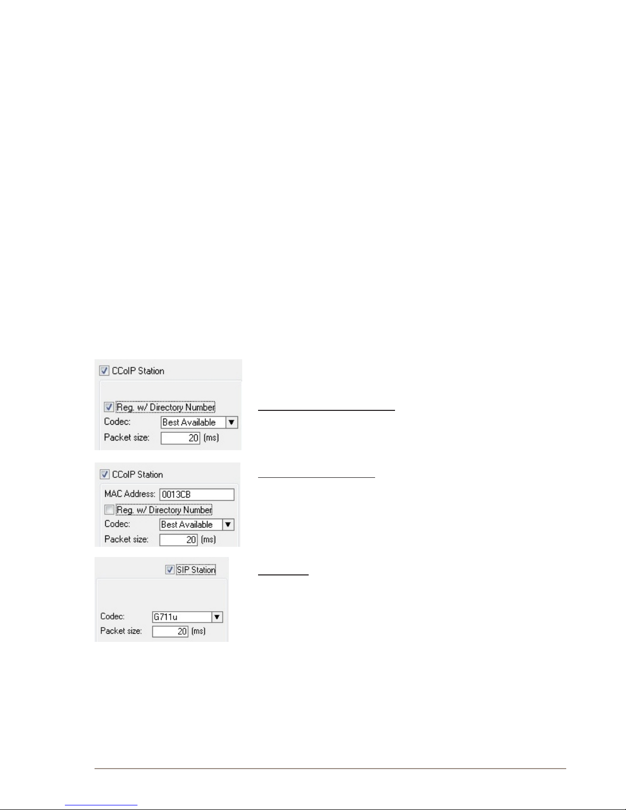
33
AlphaCom XE - Installation, Conguration & Operation
A100K10805
- The text should normally be the station location or the subscriber’s
name. The maximum number of characters is 16 including the
station directory number.
● Visibility can be set to Local or Global. Visibility is related to
AlphaNet when cluster programming is used. See section 6.2.6.
- Local: station can be addressed inside the node only.
- Global: station can be reached from all nodes in a cluster.
A cluster is a subnet of a network, and consists of a number of dened
nodes.
● Station Type is used to dene the type of station on the actual
physical number.
- Master Station is the default option. This setting will automatically
detect the type of station connected.
- Sub Station should be selected for stations with limited keypad
and PA couplers to avoid e.g. “call me” messages.
- Display Station can be selected to ensure faster and safer line
error detection on stations with displays.
Other special station options can be selected to obtain optimal
performance and programming for the relevant stations.
● CCoIP or SIP stations are selected by ticking the appropriate
checkbox.
● The CCoIP Station checkbox results in a eld for MAC address and
a checkbox for registration with directory number.
- AlphaCom XE can use both methods for identifying an IP station.
When conguring an IP station in AlphaPro, you must select which
methods to use to identify the IP station. The advantage of using
registration by directory number is that it is easier to replace the station
at a later stage as this does not require new settings in AlphaPro.
Directory Number registration
- This is the default registration for CCoIP stations.
- Tick the Reg. w/Directory Number checkbox to register the
station.
MAC address registration
- Untick the Reg. w/Directory Number checkbox to bring up the
MAC address eld.
- Enter the station’s MAC address.
The MAC address can be found by logging into the web interface of
the IP station or AlphaWeb under System Monitoring >
Stations >Uncongured.
SIP Station
Tick the SIP Station checkbox if the station is a SIP telephone.
When a change has been made to a directory number, the OK and
Cancel buttons become active.
The settings for a station can be swapped with another station by doing
the following:
1. Highlight the rst station in the list
2. Click the Copy button and then highlight the second station
3. Click the Swap button to swap the two stations.
L Ordinary analog telephones can be connected by using ATLB
cards. No conguration is needed to make the phone function
as an ordinary station. The ‘station type’ is set to Master
Station.
Page 34
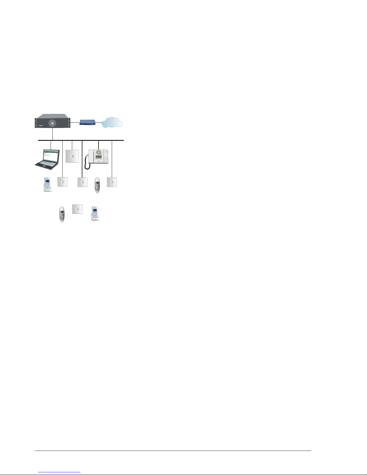
34
A100K10805
AlphaCom XE - Installation, Conguration & Operation
5.2 AdditionalIPandSIPStationConguration
Complete information about the mounting and conguration of IP
stations are found in the manuals:
- A100K10788 IP Master Station Installation & Conguration
- A100K10803 IP Substation Installation & Conguration
SIP stations and gateways are described in the manuals:
- A100K10812 SIP Substation Installation & Conguration
- A100K10333 SIP Analog Gateway
- A100K10390 SIP GSM Gateway
5.3 IPDECTSIPStationConguration
A typical IP DECT System comprises the following components:
- IP DECT Server 6000
- Base Stations
- Repeaters
- Administrative Computer
- Handsets and accessories
The IP DECT Server 6000 communicates with the AlphaCom exchange
over a LAN (Local Area Network).
The conguration process includes:
- Conguring the Server
- Conguring the Base Station
- Registering a Handset
- Subscribing a Handset
- Conguring the Exchange
The complete procedure is described in the manuals:
- A100K10652 IP DECT Installation & Conguration
- A100K10777 IP DECT Quick Conguration Guide
AlphaCom XE7
PBX/PSTN
Administration
AlphaCom Exchange
IP DECT
Server
IP Intercom
Station
Base
Station
Base
Station
Base
Station
Repeater
DECT
Handset
DECT
Handset
DECT
Handset
DECT
Handset
LAN
SIP Gateway
Page 35
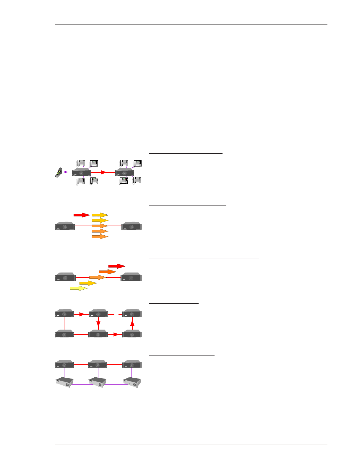
35
AlphaCom XE - Installation, Conguration & Operation
A100K10805
6 AlphaNet
6.1 Overview
AlphaNet is STENTOFON’s internal networking technology developed
for critical communications. Some of the feature highlights of AlphaNet
are:
● Group and conference calls
● VoIP bandwidth management
● Priority handling of events and resources
● Alternative routing
● Backwards compatibility
● All features available over the network
● VoIP, digital and analog infrastructure support
● SIP clients
Group and conference calls
AlphaNet has full group and conference call capability.
Each AlphaCom XE has a built-in multi-party conferencing unit,
providing local mixing for group and conference calls. This local mixing
allows AlphaCom XE to only use a single VoIP channel when setting up
a group or conference call between servers.
VoIP bandwidth management
AlphaNet provides bandwidth management, limiting the VoIP bandwidth
from taking more capacity than provisioned.
If a high priority call is set up when all VoIP channels are occupied,
AlphaCom XE will immediately release the call with the lowest priority,
thus allowing the high priority call to proceed.
Priority handling of events and resources
All calls and events that are sent between nodes are marked with
priority.
This allows the system to act upon the priority, presenting and handling
the events and calls in the correct order.
Alternative routing
Alternative routing of calls allows call completion even when the primary
AlphaNet route is down.
For alternative routing, AlphaCom XE can either use its secondary IP
interface or route the call over a traditional interface such as an analog
or digital line.
Backwards compatibility
AlphaCom XE provides 100% backwards compatibility between
traditional AlphaNet technologies and the new VoIP AlphaNet.
This backwards compatibility allows the mixing of new AlphaCom XE
nodes working over IP with current nodes so conguration can be
maintained.
L AlphaCom XE has two RS232 ports which can be used for
AlphaNet. If more ports are needed, an Ethernet to RS232
converter must be used.
AlphaCom XE7 AlphaCom XE7
1234 5
STENTOFON
VMPD619
*
#
1 2
3
4
5 6
7
8
9
0 C
M
VINGTOR
1234 5
STENTOFON
VMPD619
*
#
1 2
3
4
5 6
7
8
9
0 C
M
VINGTOR
1234 5
STENTOFON
VMPD619
*
#
1 2
3
4
5 6
7
8
9
0 C
M
VINGTOR
1234 5
STENTOFON
VMPD619
*
#
1 2
3
4
5 6
7
8
9
0 C
M
VINGTOR
1234 5
STENTOFON
VMPD619
*
#
1 2
3
4
5 6
7
8
9
0 C
M
VINGTOR
1234 5
STENTOFON
VMPD619
*
#
1 2
3
4
5 6
7
8
9
0 C
M
VINGTOR
1234 5
STENTOFON
VMPD619
*
#
1 2
3
4
5 6
7
8
9
0 C
M
VINGTOR
1234 5
STENTOFON
VMPD619
*
#
1 2
3
4
5 6
7
8
9
0 C
M
VINGTOR
LO
LO
MED
MED
MED
HI
X
AlphaCom XE7 AlphaCom XE7
LO
MED +
LO +
MED
HI
AlphaCom XE7 AlphaCom XE7
X
A
B
AlphaCom XE7 AlphaCom XE7 AlphaCom XE7
AlphaCom XE7AlphaCom XE7AlphaCom XE7
AC AC AC
IP
IP
RS232 RS232
RS232
RS232
RS232
AlphaCom XE7 AlphaCom XE7 AlphaCom XE7
AC-XE AC-XE AC-XE
Page 36
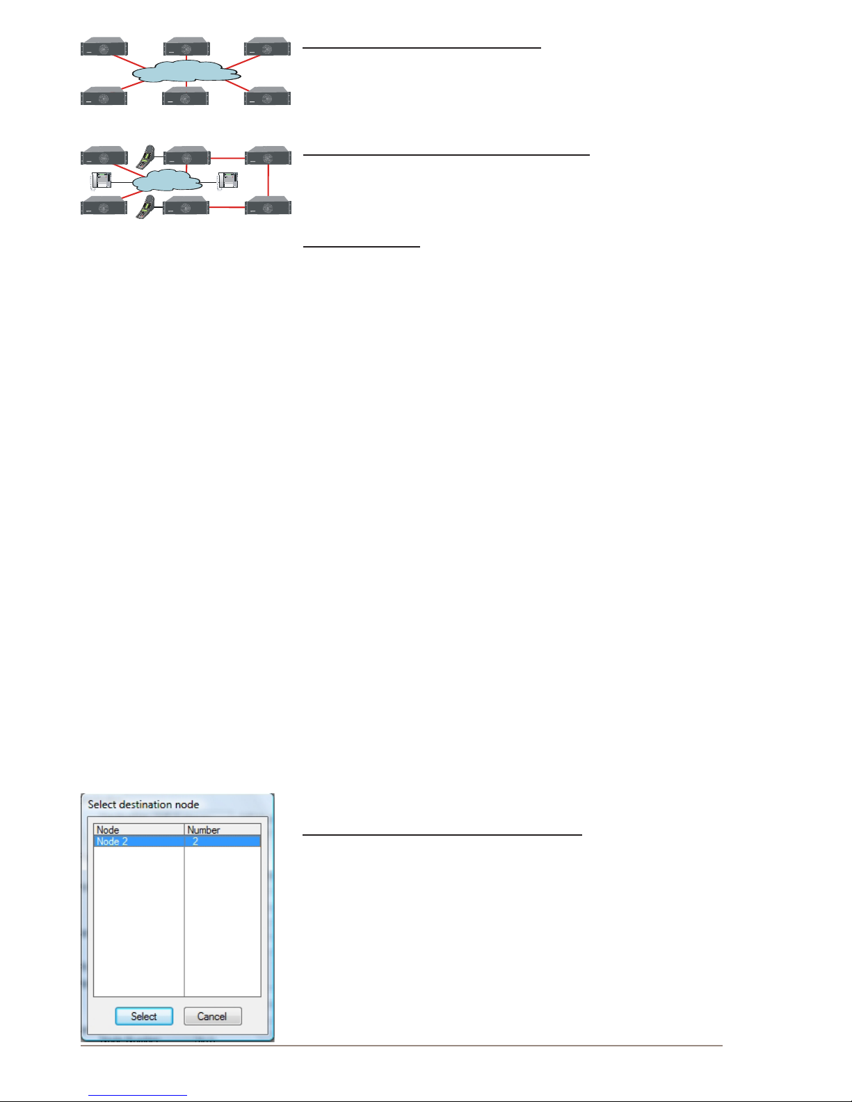
36
A100K10805
AlphaCom XE - Installation, Conguration & Operation
All features available over the network
Consistent features and services across the enterprise regardless of
location enhances user friendliness.
AlphaCom XE provides all current AlphaNet features available today,
including the enhanced features of LAN/WAN connection.
VoIP, digital and analog infrastructure support
AlphaNet works over any infrastructure, whether it is IP, digital or
analog.
SIP client interface
AlphaNet provides integration with GSM, analog, ISDN and DECT
telephones via SIP gateways. Most system functions are available
between the telephones and intercom stations.
6.2 VoIPAlphaNetConguration
6.2.1 Overview
See the Network Design Guide A100K10313 for more information.
The following procedure is required when conguring AlphaNet:
● Insert AlphaNet license if VoIP AlphaNet should be used
● Create all the exchanges in the AlphaNet
● Create AlphaNet data routing
● Create AlphaNet audio routes
● Update the directory
6.2.2 Insert AlphaNet license
This must be done if VoIP AlphaNet should be used (see section 3.3).
6.2.3 Create all the exchanges in the AlphaNet
Dene the exchanges in AlphaPro under Network & Exchanges. See
section 4.3 on how to create the exchanges.
L In some cases, it is not desired to program all the exchanges
in the AlphaNet in the same AlphaPro database. In this case
you should add the exchange in the network but un-tick the
checkbox for ‘AlphaNet - Adm. Here’.
6.2.4 Create AlphaNet data routing
AlphaNet link between AlphaCom XE servers
● Select the AlphaCom XE server in AlphaPro
● Click the Exchange & System icon
● Click Net Routing
● Click Insert
● Select the destination AlphaCom node for the AlphaNet
AlphaCom XE7 AlphaCom XE7 AlphaC om XE7
AlphaCom XE7AlphaCom XE7AlphaCom XE7
AlphaCom XE7 AlphaCom XE7 AlphaCom XE7
AlphaCom XE7AlphaCom XE7AlphaCom XE7
RS232
IP
123 4 5
STENTOFON
VMPD619
*
#
1 2
3
4
5 6
7
8
9
0 C
M
VINGTOR
123 4 5
STENTOFON
VMPD619
*
#
1 2
3
4
5 6
7
8
9
0 C
M
VINGTOR
Page 37
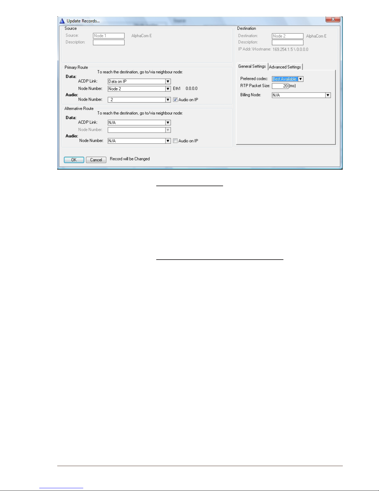
37
AlphaCom XE - Installation, Conguration & Operation
A100K10805
Congure primary route
● Select Data on IP as ACDP Link
● Select node number for both Data and Audio
● Tick the Audio on IP checkbox if a VoIP audio link shall be used
● Option: Congure an alternative route
● The Preferred codec should be set to Best Available
● Click OK
AlphaNet link to traditional AlphaCom servers
● Select the AlphaCom server
● Click the Exchange & System icon
● Click Serial Ports
● Select a free ACDP Link (AlphaCom Data Protocol)
● Click Change
● Tick the Enabled checkbox to enable the port and select the serial
port for AlphaNet from the Port Type drop-down list.
● Set Link Type as Stentofon Link Layer – AlphaNet
● Click OK and close the serial port window
● Select Net Routing
● Click Insert
● Select the remote AlphaCom node for the AlphaNet
● Congure the primary route
● Select the ACDP Link that was congured for AlphaNet
● Select the Node Number for both Data and Audio
● Do NOT tick the Audio on IP checkbox
● Option: Congure an alternative route
● Click OK
L For each AlphaCom, it is required to congure AlphaNet links
to the AlphaComs that it communicates with.
Page 38
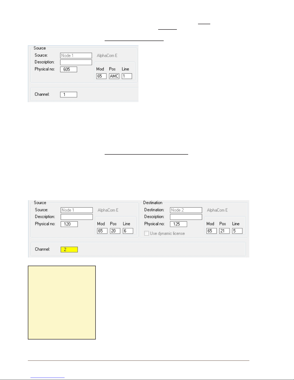
38
A100K10805
AlphaCom XE - Installation, Conguration & Operation
6.2.5 Create AlphaNet audio channels
Audio channels must be dened when using a Static AlphaNet license.
It is not necessary when a Dynamic AlphaNet license is used.
Create VoIP audio channels
In AlphaPro, select the AlphaCom exhange:
● Click the Exchange & System icon
● Click Net Audio
● Click Insert
● Select the destination node and click Select
● Enter the parameters as shown
● Conrm by clicking OK
Repeat the insert operation for the number of wanted VoIP audio
channels.
L The physical numbers 605 to 635 are logical numbers inside
AlphaCom XE and are reserved for VoIP AlphaNet and SIP.
● Click Close to close the AlphaNet Audio Connections window
● Click Close to close the Exchange Information window
Create circuit switched audio channels
● Select the AlphaCom exhange
● Click the Exchange & System icon
● Click Net Audio
● Click Insert
● Select the destination node and click Select
● Enter the physical numbers in the Source and Destination nodes as
shown
● The module, position and line numbers are automatically dened
when the physical number is entered. See the appendix for an
overview of physical numbers in AlphaCom.
● Conrm by clicking OK
● Repeat the Insert procedure for the number of desired audio
channels.
6.2.6 Cluster node programming
Cluster programming is an option for simplifying the programming
and updating of numbers in AlphaNet when operating with integrated
number series.
The exchanges can be given a Cluster Node Number. Nodes with the
same Cluster Node Number (1-255) are members of the same cluster.
Mod: Automatically entered
when the physical
number is dened.
Connect to main Frame:
Module 65 - Master
Module 66 - 1st Slave
Module 67 - 2nd Slave
Module 68 - 3rd Slave
Pos: Board position number
(1-26)
Line: Station line on ASLT
board (1-6)
Page 39
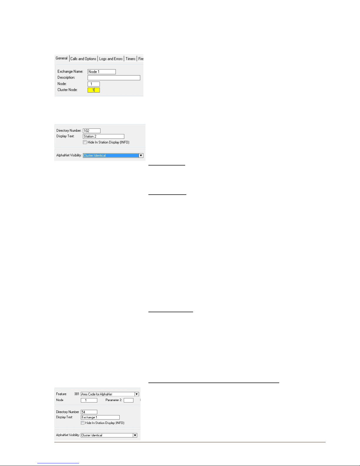
39
AlphaCom XE - Installation, Conguration & Operation
A100K10805
Stations in these nodes can be given one of three AlphaNet Visibility
cluster modes.
To get access to the AlphaNet Visibility menu, the exchange has to be
given a Cluster Node Number
● Click the Exchange & System icon
● Select the actual exchange
● Click System
● Enter a number between 1-255 in the Cluster Node eld
● Verify by clicking OK
● Repeat the procedure for all actual exchanges
- Nodes with the same Cluster Node Number are members of the
same cluster.
● Click the Users & Stations or Directory & Features icons to select
or create new directory numbers to be changed from the default
status Cluster Local
● Select Cluster Global or Cluster Identical from the drop-down menu
under AlphaNet Visibility
Cluster Local
The directory number will not be copied to the other exchanges in the
cluster node.
Cluster Global
The directory number and name will immediately and automatically be
copied to the other exchanges in the AlphaNet database as a global
number (feature 83).
If the number exists from before in any of the other exchanges, it will be
deleted. AlphaNet Visibility will be set to Cluster Automatic in the other
exchanges.
● Modifying:
- When modifying the number or name of an existing global user,
do the modication in the exchange where the user is physically
connected, i.e. where the visibility is set to Cluster Global.
● Deleting:
- When deleting a directory number that has visibility Cluster Global
or Cluster Automatic, it will automatically be deleted from all cluster
nodes.
Cluster Identical
The directory number and name will be copied to the other exchanges.
The feature number will be identical in all exchanges, i.e. the feature will
remain local in each exchange but with the same number and name.
AlphaNet Visibility will be set to Cluster Identical in all exchanges.
6.2.7 Update the directory in each exchange
Create directory number for AlphaNet Area Codes
● Click the Directory & Features icon
● Select the directory number for the exchange
● Click Insert
● Select Area Code for AlphaNet – 81 from the Feature menu
● Enter the node number for the exchange owning the area code
● Enter the directory number you want to use as area code
Page 40
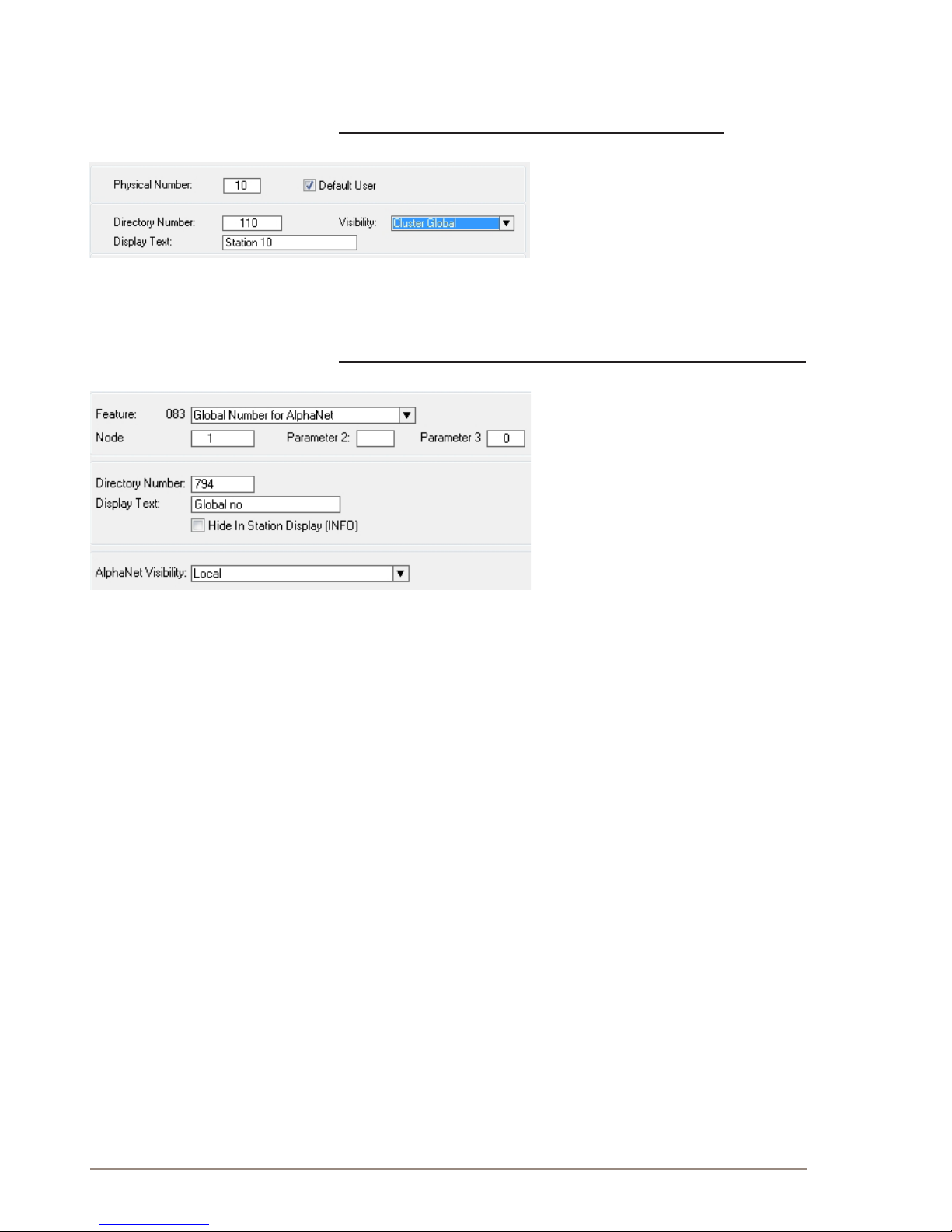
40
A100K10805
AlphaCom XE - Installation, Conguration & Operation
● Select Cluster Identical from the AlphaNet Visibility menu
● Conrm by clicking OK
Make AlphaCom stations visible in the AlphaNet cluster
● Click the Users & Stations icon
● Select the station that should have a
global number
● Select Cluster Global from the
Visibility drop-down list
● Conrm by clicking OK
Cluster Global can also be set from the Directory & Feature menu. All
stations can then be set in one operation.
Manually create directory number for Global Numbers for AlphaNet
● Click the Directory & Features icon
● Click Insert
● Select Global Number for AlphaNet –
83 from the Feature drop-down list
● Enter the node number for the
exchange
● Enter the directory number you want
to use as global number
● Conrm by clicking OK
● Leave the AlphaNet Visibility at
Local
Page 41
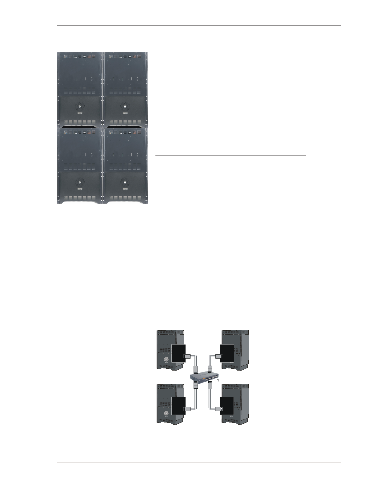
41
AlphaCom XE - Installation, Conguration & Operation
A100K10805
7 Multi-Module Network
7.1 Overview
If the number of subscriber lines in one AlphaCom XE26 (138 lines) is
exceeded, up to 4 modules can be combined to form a multi-module unit
with a maximum capacity of 552 lines.
The multi-module concept uses one master module and up to three
slave modules. The multi-module acts as one server with full integration
of all features. All conguration data is stored on the Master AMC board.
The connection between the modules is via an IP network similar to
AlphaNet.
● Multi-module is recommended when the modules are located in the
same building/complex.
● AlphaNet is recommended when the modules are located apart from
each other
Main features of AlphaCom XE IP-based Multi-Module:
● Same high degree of feature integration as conventional multi-
modules
● No additional AlphaCom hardware required
● License is needed in the master module only
● Point-to-point connections
(not in a ring as in conventional multi-modules)
● The modules need to be on the same LAN
● Optional Autonomic mode
- The AMC Master can be set to copy its contents to the slave
modules over a 28 hour period
- In case of master-slave communication error, the slave will restart
in autonomic mode, making it possible to communicate normally
within each module.
7.2 Installation
● Interconnect the modules via an Ethernet switch as shown in the
gure.
● Perform a cold start on each module separately
Eth 1
Eth 1
Eth 1
Eth 1
10.1.1.1
10.1.1.3
10.1.1.4
10.1.1.2
AMC
AMC
AMC
AMC
IP
IP
IP
IP
Master
Slave 2
Slave 3
Slave 1
Phys. No.: 1-138
Phys. No.: 139-276
Phys. No.: 277-414
Phys. No.: 415-552
Ethernet switch
100Mb/s
Page 42
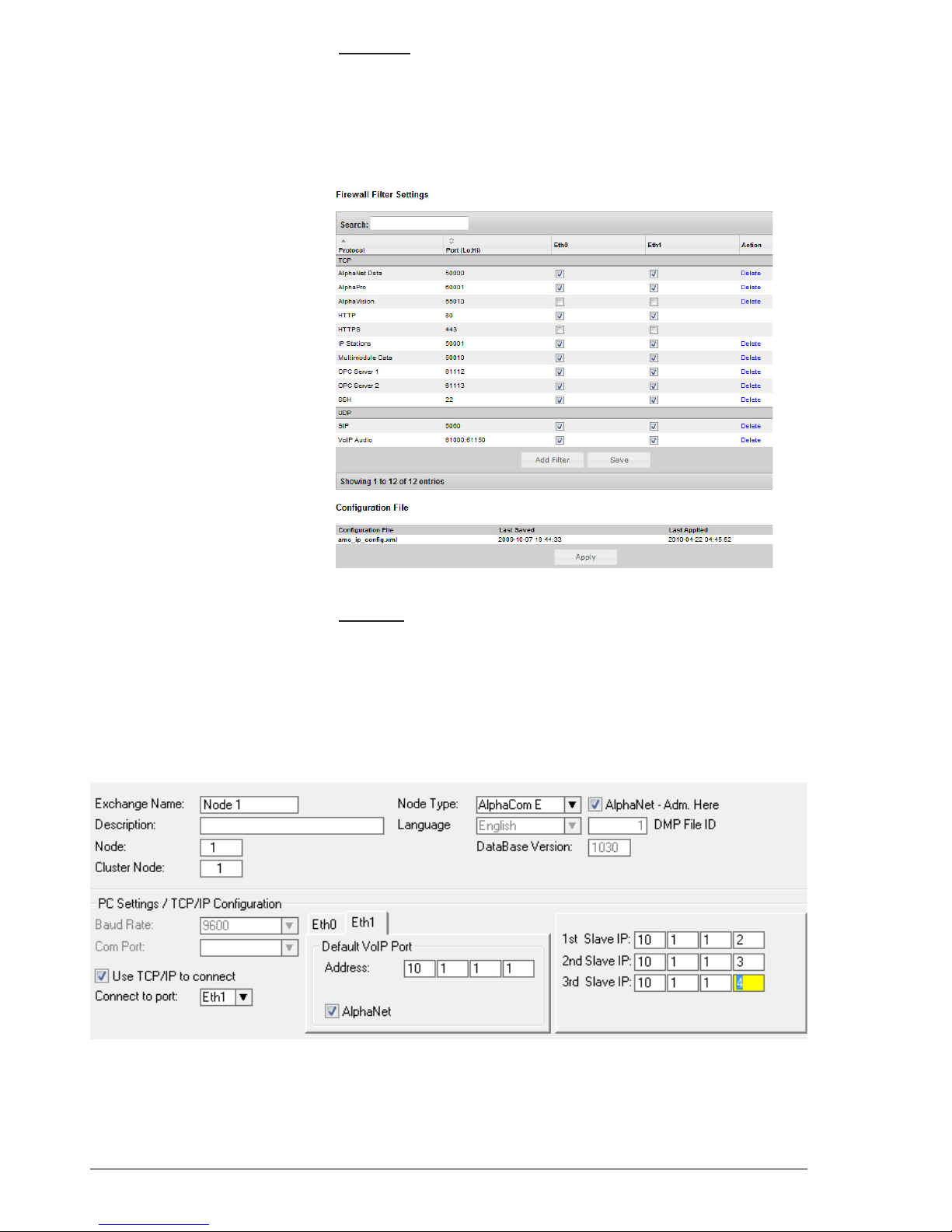
42
A100K10805
AlphaCom XE - Installation, Conguration & Operation
AlphaWeb
● Assign an IP address to each module (see sections 3.4.2 and 3.4.3)
● Enable Multimodule Data and VoIP Audio in the Filters setting (see
section 3.4.4)
● Enter the Master license key to enable the Multi Module (see section
3.3)
AlphaPro
● Click the Exchange & System icon
● Select the multi module exchange from the list
● Click the System button
● Select Eth1 as the Default VoIP Port and check the Address
● Enter the IP address of the slave modules.
L Only the Master Module supports serial port drivers and other
central equipment and licenses like RIO, Paging, AlphaNet, SIP
trunk node and SIP Registrar Node.
Page 43
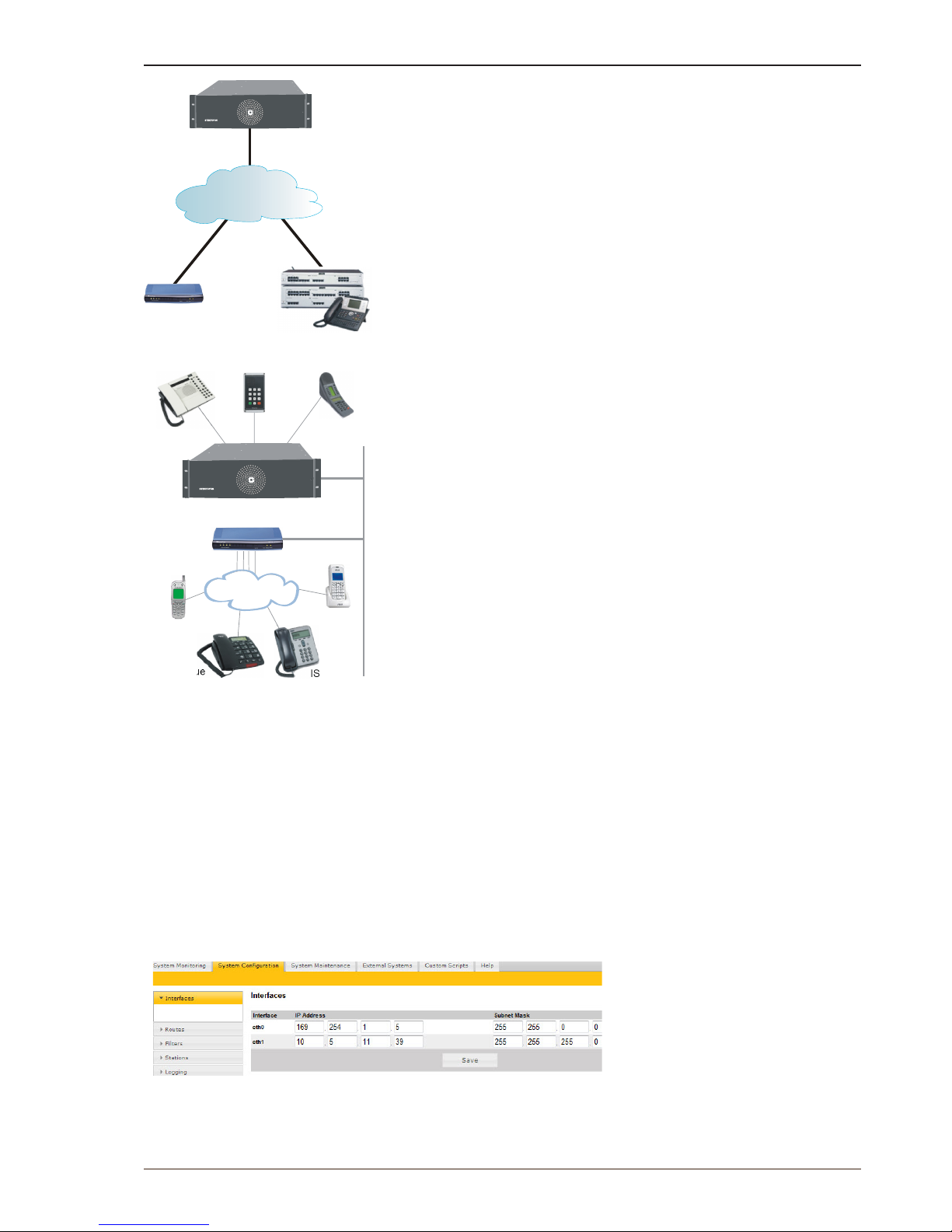
43
AlphaCom XE - Installation, Conguration & Operation
A100K10805
8 External Communication
8.1 SIP Trunk License
The SIP Trunk License makes it possible to connect Alphacom XE
directly to iPBXs over IP networks. SIP trunks provide seamless
integration between Alphacom XE and other telecom systems
supporting advanced functions like ‘see who is calling’ and shared
numbering plans.
The SIP license is tested and veried for several SIP systems on the
market. Please contact STENTOFON Support to get the latest list of
veried equipment and systems.
The license will operate on all STENTOFON Alphacom XE systems and
upgraded AlphaCom systems.
8.2 GatewayConguration
This section describes the setup of the AlphaCom XE system with
AudioCodes MP-114/118 SIP Gateway, rmware version 5.4 and
5.6. The most common features used in an AlphaCom/AudioCodes
interconnection are covered.
A full description including AudioCodes programming is found in the SIP
Gateway Conguration Guide A100K10333 and in AlphaWiki under the
SIP category.
See also the SIP GSM Gateway Conguration Guide A100K10390.
The conguration of AlphaCom XE with the SIP gateway includes the
following steps:
● Using AlphaWeb
- Assign IP address to the AlphaCom Ethernet port
- Insert SIP Trunk licenses
- Firewall (lter) settings
● Using AlphaPro
- Create a SIP Trunk Node
- Dene the AlphaCom/SIP routing
- Create prex numbers
- Update the exchange
8.3 AlphaComCongurations
8.3.1 AlphaWebCongurations
Assign IP address to the AlphaCom E Ethernet port(s)
● Log on to AlphaWeb and select SystemConguration > Interfaces
● Enter a valid IP address on the Ethernet port.
In the example below, Ethernet port 1 is used. Consult your network
administrator to obtain the IP address.
AlphaCom XE7
GSM
ISDN
SIP trunk
FXO ports
DECT
Analogue
PSTN / PABX
AlphaCom XE7
10.5.101.42
10.5.101.44
255.255.255.0
255.255.255.0
Page 44
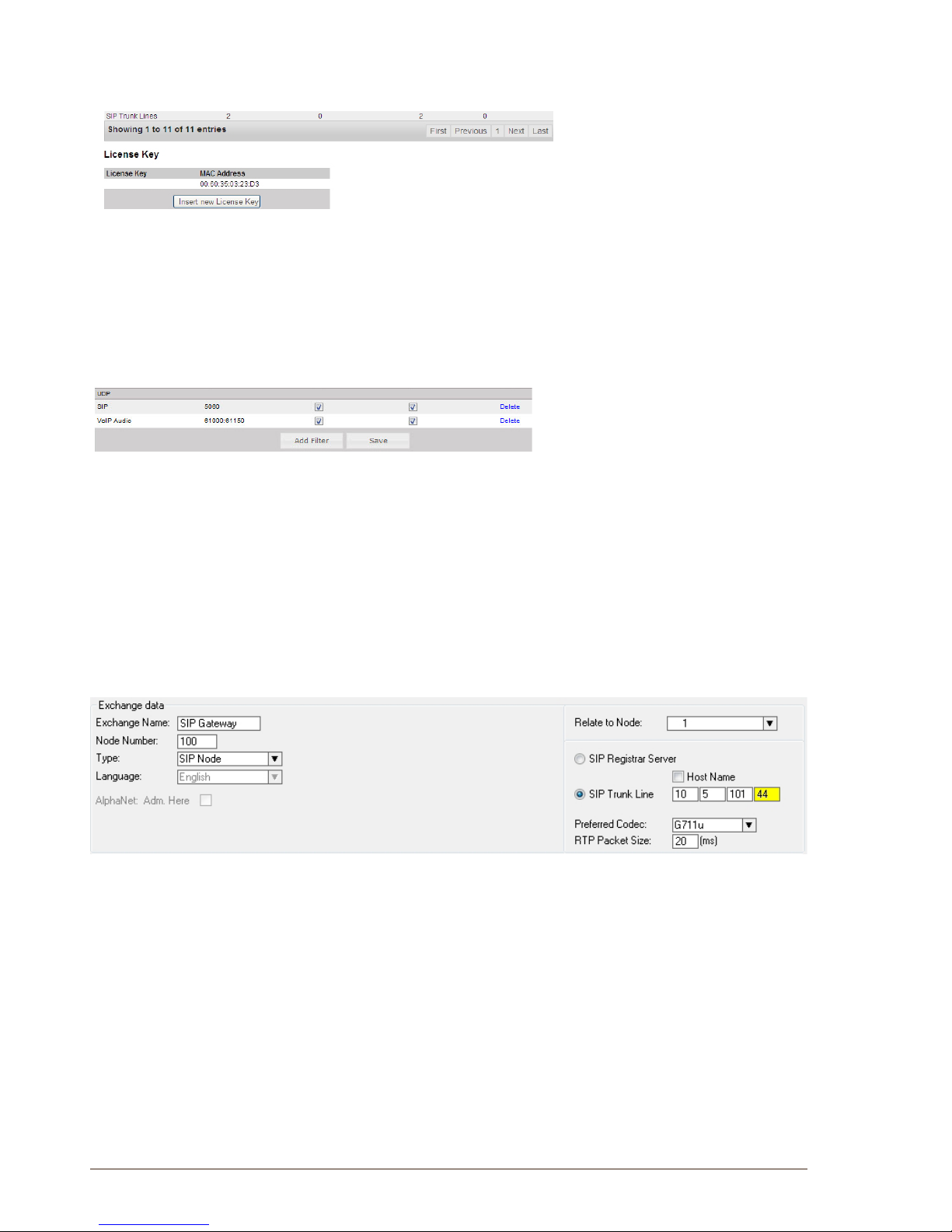
44
A100K10805
AlphaCom XE - Installation, Conguration & Operation
8.3.2 Insert SIP Trunk licenses
● Log on to AlphaWeb and select SystemConguration > Licensing
● Install the SIP Trunk license by clicking Insert new License Key
8.3.3 Firewall(lter)settings
● Log on to AlphaWeb and select SystemConguration > Filters
● Enable the SIP protocol and VoIP Audio on the desired Ethernet
port by ticking the relevant checkboxes (default enabled for Ethernet
port1).
8.4 AlphaProConguration
8.4.1 Create a SIP Trunk Node
● From the AlphaPro main menu, click the ‘+’ button next to the Select
Exchange drop-down list to create a new exchange.
● The exchange Type must be set to SIP Node.
● Click the radio-button for SIP Trunk Line and enter 10.5.101.44
- The SIP Trunk IP address must be identical to the IP address of the
SIP Gateway.
L If AlphaCom is congured with a SIP Registrar node in addition
to the SIP Trunk node, the SIP Registrar node must have a
lower node number than the SIP Trunk node.
8.4.2 DenetheAlphaCom/SIProuting
● Select Exchange & System > Net Routing and click the Insert
button to create a route between AlphaCom and SIP Gateway.
● Select SIP Link from the ACDP Link drop-down list
● Tick the Audio on IP checkbox
● Set Preferred codec to G711u and RTP Packet Size to 20 ms.
● Conrm by clicking OK
Page 45
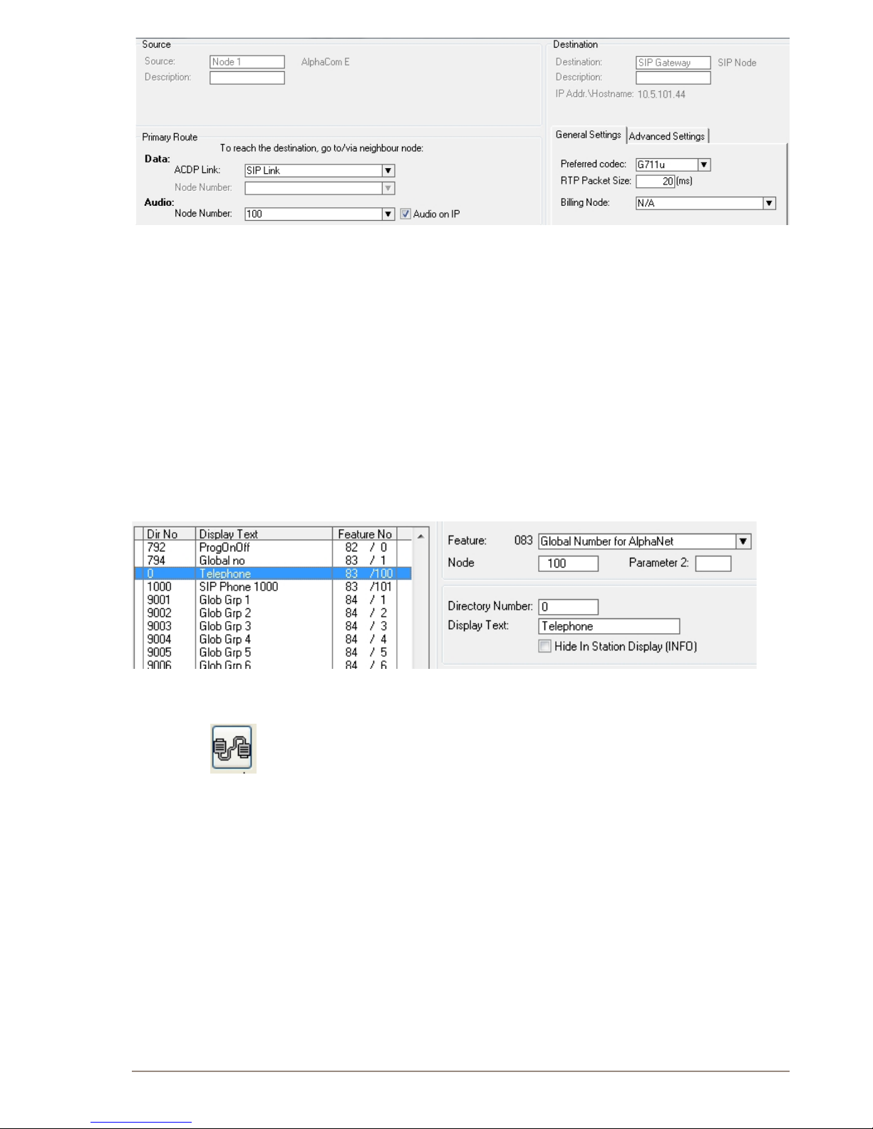
45
AlphaCom XE - Installation, Conguration & Operation
A100K10805
8.4.3 CreatePrexnumber
The directory number (prex) used to access the telephone line must be
programmed in the AlphaCom directory table with Feature 83
● Click the Directory & Features icon
● Select Global Number for AlphaNet – 83 from the Feature drop-
down list
● Click Insert
● Enter the Node number for the SIP Trunk node (100 in this example)
● Enter the Directory Number for the SIP trunk
- In this example, the default directory number 0 has been modied
to be used as a prex.
● Enter a Display Text
● Conrm by clicking OK
8.4.4 Update the exchange
● Log on to the exchange by clicking the Communication icon
● Update the exchange by clicking the SendAll button.
● Reset the exchange after the send operation is completed.
8.5 Billing System
The VINGTOR Billing application makes it possible to manage and
administer the communication fees and expenses for your VINGTOR
ACM system. The application provides access authorization to external
communication. The calling users will be identied based on PIN or
subscriber number. Each user will have a set of authorization criteria
such as credit line, and trunk type, which determines if he/she will be
granted access to external communication.
The VINGTOR Billing application is a full billing system which allows you
to generate revenues from your VINGTOR system and to administer a
set of billing scenarios. Fees can, for instance, be calculated based on
carrier type, duration, called number, and time of day. Billing of users
can be done either by pre-paid or post-paid payment methods.
Page 46
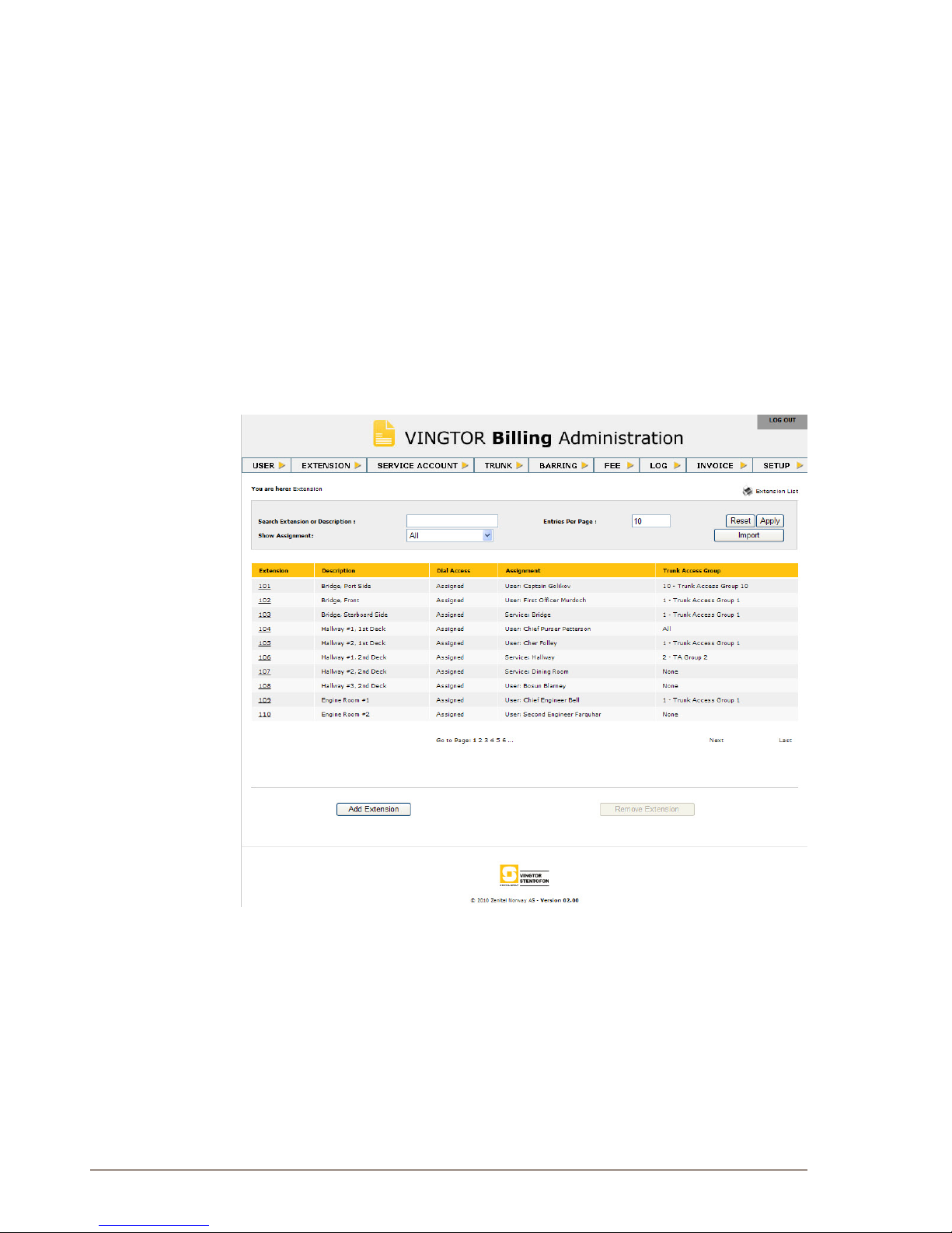
46
A100K10805
AlphaCom XE - Installation, Conguration & Operation
The application has a user-friendly web interface, making the job of
the billing administrator much easier. The administrator can use a
standard web browser to log into the system. From the web browser, the
administrator is able to:
● Print billing invoices
● Print and view usage reports
● Change billing setup
Five different product versions of the Billing System are available with
capacity from 2 to 32 external trunk lines, all catering to a maximum of
400 users.
See the manual A100K10590 Billing System Conguration Guide for
further information.
Page 47
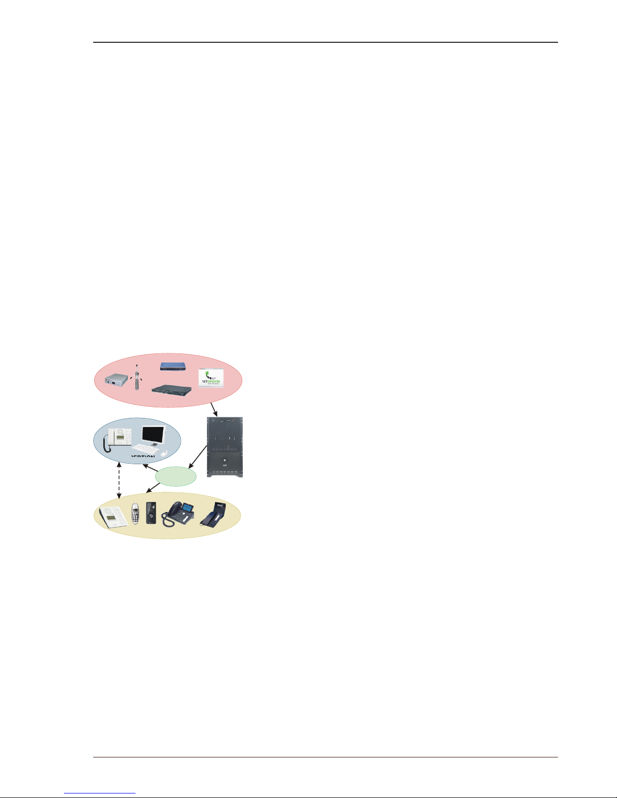
47
AlphaCom XE - Installation, Conguration & Operation
A100K10805
9 Audio Messaging
The Audio Messaging features are used to provide various messaging
services and PA broadcast in the AlphaCom XE Audio Server. The
messages are pre-stored in ash memory on the main processor board
and can be played back to individual stations or a group of stations to
provide information such as:
● Voice guidance at doors and elevators
● Security voice response
● Auto-attendant and voice guidance
● Information messages
● Alarm and evacuation messages
There are four ways to implement audio messaging services in the
AlphaCom XE:
● ASVP software module
● ASVP board
● Upload customized WAV les from AlphaWeb
● Record customized messages from an intercom station
ASVP = AlphaCom Stored Voice Playback
9.1 Stored Voice Messages
Both the Basic and the Enhanced Audio Messaging licenses have the
capability of storing and playing audio messages from the Alphacom XE
server. The feature set of the license is compatible with that of the ASVP
board but offers some important additional functionalities.
The audio messaging license offers a broad set of applications and
functions, some of which are:
● Live PA and group call broadcast with recall for handling feedback
and verifying messages
● Pre-stored PA and group call broadcast
● Scheduled or event-based PA and group call broadcast
● Auto-attendant with voice guided menus for handling incoming calls
● Voice response for ‘call request waiting’ messages and absence
messages
● Integration with 3rd party systems via OPC, STENTOFON SDK and
STENTOFON Data Protocol
When the Audio Messaging license is activated, the Alphacom XE
server will have a set of default messages such as absence, alarm
and general information messages. The default messages can be
changed and new messages can be added. Both new and modied
messages can be recorded from an intercom station or created on a PC.
Your favorite audio and music programs can be used to create these
messages, which can then be uploaded to the Alphacom XE server via
AlphaWeb.
The audio messaging license comes in three versions – Basic,
Enhanced, and PA Recall. The licenses are different in terms of:
● Audio storage capacity
● Set of default audio messages
● Interactive complex message generation (Enhanced License only)
● Compatibility with hardware versions
RECEPTION
X-Lite
Analogue FXO
GSM
ISDN
SIP Trunk
CALL PICK-UP
(+47) 40 00 25 00
Inbound
calls
AUTO
ATTENDANT
Page 48
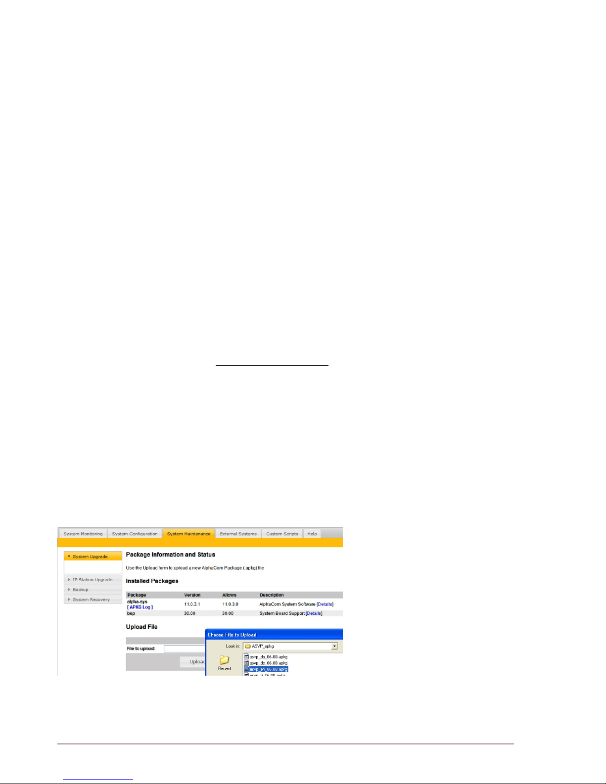
48
A100K10805
AlphaCom XE - Installation, Conguration & Operation
9.1.1 Messageidentication
Stored Voice Messages are reached by a combination of two numbers:
Message Group and Group Index.
The AMCD application uses this reference as the starting point when
a message shall be played back. The same references are used for
display texts to be looked up from the Message Description File.
9.1.2 ASVP software module
The ASVP module and the ASVP board support composing a voice
message in run-time by using sequences of voice les and also
composing parameterized messages.
Parameterized messages can be used to pronounce numbers, dates
and times from the SW control. A Message Group/Index reference will
result in playback of a sequence of WAV les
A set of standard audio messaging services can be implemented by
uploading a language package le to AlphaCom XE using the web
interface, AlphaWeb. The standard messages comprise:
● Absence messages
● Information messages
● Help messages
● Alarm messages
The types of messages that actually become available depends on the
installed Audio Messaging license.
Install language package
The language le has the format asvp_xx_06.00.apkg, where xx is the
actual language and 06.00 is the version number.
Before the installation can start, you need to download the language le
from Zenitel’s support websites AlphaWiki or Partnernet to your PC.
● In AlphaWeb, select System Maintenance > System Upgrade
● Click Browse to choose the language le and click Upload
● Click the Install button
The messaging services becomes available immediately after the
installation. No reset is required.
L Note that:
● It is only possible to install a single
ASVP package at a time.
● When installing a new version of the
same package, just install over the
old one.
● When installing a different ASVP
package, delete the old ASVP
package rst.
9.1.3 ASVP board
The ASVP board has been discontinued and replaced by the ASVP
Software Module.
Page 49

49
AlphaCom XE - Installation, Conguration & Operation
A100K10805
The ASVP board has the same set of standard messages as the ASVP
Software Module.
No conguration is required when the ASVP board is used. Insert
the board in any free board position in the AlphaCom server and the
messaging services will be automatically activated when the system is
powered up.
L The ASVP board does not require any license.
9.2 Customized Message Upload
The ASVP software module provides the AlphaCom XE server with a set
of default messages such as absence, alarm, and general information
messages.
It is possible to modify or add new messages to the system by uploading
audio les to the AlphaCom XE server using AlphaWeb.
- If the ASVP Software Module is present, a web loaded message
will mask the corresponding ASVP message.
- Deleting the web loaded message will unmask the ASVP message.
An Easy Message is one single WAV le for each Message Group +
Group Index.
● Web loaded messages are uploaded individually via AlphaWeb
● Station-recorded messages are recorded from a station
The audio le can be recorded on a PC or in a professional studio if high
quality playback is required. The audio le must be in WAV format.
The following codecs are supported:
● PCM les at 16kHz sample rate (linear 16bit), mono (1 channel)
● MS ADPCM at 16kHz sample rate, mono (1 channel)
● IMA ADPCM at 16kHz sample rate, mono (1 channel)
When a request is made to AlphaCom XE to play a message, it will
search for matching group/index in the following order:
1. Station-recorded message
2. Web loaded message
3. Message in the ASVP Software Module on the AMC-IP board
4. Message on the ASVP board (if present)
9.2.1 Upload messages from AlphaWeb
When uploading a WAV le, the le must be associated with the relevant
intercom feature by means of two parameters: Message Group and
Group Index.
In the tables below, you can nd the link between the intercom feature
and the Message Group and Group Index for the message you intend to
customize.
● Log on to AlphaWeb
● Select SystemConguration> Messaging
- An Audio Messaging license must have been installed up front to
be able to access this page.
● Go to the Upload Wav File section at the bottom of the page, and
select Message Group and Group Index according to the tables
below.
● Browse to the WAV le, and select Upload.
Available
language packages:
da Danish
de German
en English
Finnish
fr French
it Italian
ko Korean
no Norwegian
sv Swedish
chn Chinese
Page 50
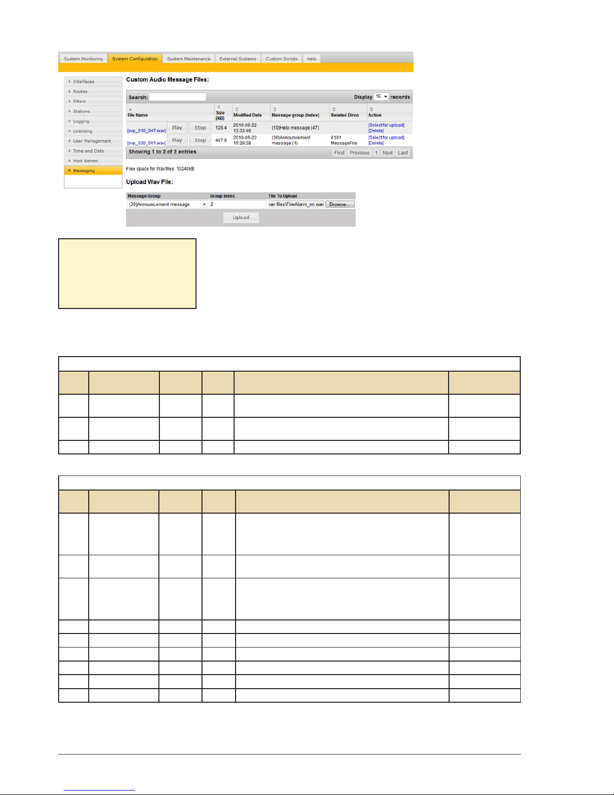
50
A100K10805
AlphaCom XE - Installation, Conguration & Operation
The le will now be renamed and stored on the ash memory on the
AMC-IP card.
The le name will be renamed to svp_ggg_iii_.wav where ggg is the
Message Group number and iii is the Group Index number.
● Select the SystemConguration> Messaging page to see and
listen to all uploaded WAV les. Any le may be deleted.
There are no restrictions on the messages that can be uploaded but the
message is checked against the installed Audio Messaging license to
see if it is available for playback.
The most relevant English messages are listed below.
VOICE GUIDANCE AND INFORMATION MESSAGES
Dir.
no.
Feature Message
Group
Group
Index
Default English ASVP message Minimum license
required
9550 Auto-attendant 11 1 Basic: 1
Enhanced: 3
622 or
623
Send Call Request 10 47 “Your call is registered, please wait” None
70 Station reset 10 42 “No messages” None
ALARM MESSAGES
Dir.
no.
Feature Message
Group
Group
Index
Default English ASVP message Minimum license
required
8191 Alarm Message 1 30 1 “Fire alarm. Please stay calm and leave the building through the
nearest exit. All exits are marked with green light. Don’t stop, but
proceed completely out of the building. Wait for further information
outside.”
Basic
8192 Alarm Message 2 30 2 “The situation is now under control, the building can again be
used. We are sorry for the inconvenience.”
Basic
8193 Alarm Message 3 30 3 “An unexpected situation has occurred. Please stay calm and
leave the building through the nearest exit. All exits are marked
with green light. Don’t stop but proceed completely out of the
building. Wait for further information outside.”
Basic
8194 Alarm Message 4 30 4 Enhanced
8195 Alarm Message 5 30 5 Enhanced
8196 Alarm Message 6 30 6 Enhanced
8197 Alarm Message 7 30 7 Enhanced
8198 Alarm Message 8 30 8 Enhanced
8199 Alarm Message 9 30 9 Enhanced
Example:
svp_030_001.wav
is group 30, index 1,
(Alarm message 8191).
Page 51
51
AlphaCom XE - Installation, Conguration & Operation
A100K10805
9.2.2 Record message from a station
It is possible to modify or add new audio messages from a Super User
station. The default directory number for the recording function is 8180.
The best result is achieved by using a station with handset for the
recording.
Recording procedure:
● Dial 8180 + the directory number of the feature that you want to
modify
- If a message already exists, the message will be played back.
- If the message is a station-recorded message, it has to be deleted
by pressing digit 0 + M-key before a new message can be recorded
● Press the M-key to start recording.
- Each M-key press starts a new recording
● Release the M-key to stop recording
- The recorded message is played back
● Press digit 7 to listen once more to the message
● Press digit 8 to store the message
● Press the C-key to cancel the recording without storing the
message
SOME FEATURE EXAMPLES
Dial Feature Minimum license required
8180 + 9550 Auto-attendant Basic: 1 auto-attendant
Enhanced: 3 auto-attendants
8180 + 623 Send Call request None
8180 + 70 Station reset None
8180 + 8191-8199 Alarm Message 1-9 Basic: 3 alarm messages
Enhanced: all alarm messages
8180 + 771-779 Absence messages Enhanced
8180 + 660-669 Voice Mail messages Enhanced
A station-recorded message will mask any corresponding web-loaded
message or ASVP message. When a station-recorded message is
deleted, the web-loaded message will be unmasked if present.
A station-recorded message will be stored as a WAV le in the ash
memory of the AMC-IP board and can be accessed from the System
Conguration> Messaging page in AlphaWeb.
The WAV le will be stored with the le name svp_ggg_iiia_.wav,
where ggg is the Message Group number, iii is the Group Index number
and a indicates that it is a station-recorded message and not a web-
loaded message.
You are only allowed to record messages according to the type of Audio
Messaging license installed.
To be able to carry out station recording, the station must have access
to features 111 and 114 in its Class of Service settings.
9.2.3 Licensing
Playback of Stored Voice Messages stored on the AMC-IP board
requires a license.
Usage of the ASVP board requires no license.
The license check is done on the Message Group/Index number at the
time a message is requested for playback. Different message groups
are used for different functions, hence, blocking per function as well as
limiting the number of different messages for a function is possible.
Example:
svp_030_001a.wav
shows that this is a station-
recorded message associated
with group 30 and index 1.
(Alarm message 8191).
Page 52

52
A100K10805
AlphaCom XE - Installation, Conguration & Operation
Licenses does not limit the duration of single messages or the total
duration of all stored messages.
Upload of Easy Messages and Station Recording features are not
restricted by license. The ASVP module is also active without any
license. The licensing only blocks the messages that can be used.
● No license
- Only ASVP help messages are available (Message Group 10)
- Standard ASVP messages by uploading ASVP Software Module
- Record own customized messages
● PA Recall license (works on AMC-IP v. 10 or 11 hardware)
- Delayed group call to prevent feedback
● Basic Messaging license (requires AMC-IP v. 11 hardware)
- ASVP help messages (Group 10)
- 1 Auto-Attendant message ( Message Group 11, index 1)
- 3 Voice Alarm Messages 8191-8193 (Message Group 30, index
1-3)
- Recall function. Delayed group call to prevent feedback
- Up to 2 Mbyte customized WAV les (Approx. 4 min. 16 sec.
speech)
● Enhanced Messaging license (requires AMC-IP v. 11 hardware)
- Unlocks all current messaging features
- ASVP help messages (Message Group 10)
- 3 Auto-attendant messages (Message Group 11, index 1-3)
- Any number of Voice Alarm Messages (Message Group 30)
- Up to 10 Mbyte of customized WAV les (Approx. 21 min. 20 sec.
speech)
- Recall function. Delayed group call to prevent feedback
- Absence Messages (771 - 779)
- Mail Messages (660 - 669)
9.2.4 Supportedaudioleformats
AlphaCom can only play back WAV container le format with 16kHz
sample rate, single channel (mono), and one of the following three
encodings
● PCM les at 16kHz sample rate (linear 16bit), mono (1 channel).
● MS ADPCM at 16kHz sample rate, mono (1 channel).
● IMA ADPCM at 16kHz sample rate, mono (1 channel)
PCM les need 32 KByte/s. The ADPCMs need 8 KByte/s (same as
G.711/G.722)
Station-recorded Easy Messages are stored as IMA ADPCM.
9.3 Recall
The Recall function lets you record a message from a station and then
dispatch the recorded message as a Group Call.
- The function is used to prevent feedback problems when making
Group Calls
- The recorded message is stored temporarily
- It is deleted when the group call is nished
- The maximum duration of a single recall message is limited to 3
minutes
- The total system storage capacity for recall is approx. 40 minutes
9.3.1 Directory numbers
The default directory numbers for “recall” broadcast are:
- 9084: Recall to group 1 (all)
- 9085-9088: Recall to groups 2 - 5
Page 53
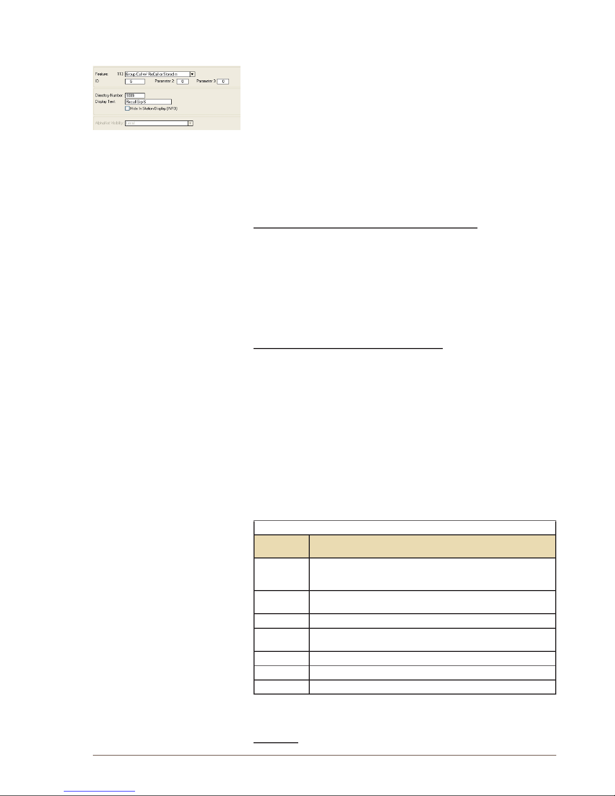
53
AlphaCom XE - Installation, Conguration & Operation
A100K10805
- 9101: Recall to global group 1 (for AlphaNet)
More recall numbers can be added from AlphaPro if required:
● In the Directory & Features window, select Insert
● Select Group Call w/Recall - 113 from the Feature drop-down list
● Enter the local group number in the ID eld
● Enter any free directory number and an appropriate display text in
the Directory Number and Display Text elds.
The recall function can also be activated via a two-step operation using
feature code 765:
● Dial 765 + group number.
9.3.2 User interface
Using the recall function from an intercom station
1. Dial the recall number (e.g. 9084 or 765+84)
2. Press the M-key to record a message
3. Release the M-key to listen to the recording
4. Press 8 to dispatch the message or:
- Press the M-key to make a new recording
- Press 7 to repeat the message
- Press the C-key to cancel the message
Using the recall function from a telephone
1. Dial the recall number (e.g. 9084 or 765+84)
2. Press the *-key to record a message
3. Press the #-key to stop the recording and listen to the message
4. Press 8 to dispatch the message or:
- Press * to make a new recording
- Press 7 to repeat the message
- Hang up to cancel
9.3.3 Optional settings
The recall user interface and the recall attributes can be altered by
modifying parameter 2 (set in AlphaPro) of the recall directory number.
By default, this parameter has value 0.
RECALL OPTIONS
Value
parameter 2
Function
1
After playback to the group has nished, the group call and the initiator
station will proceed to normal Group Call mode, and can use the M-key to
talk into the group
2
If the initiator station disconnects during playback to the group, the message
is terminated immediately
8
The initiator station will not listen to the playback to the group
32
The message is dispatched when pressing the C-key or hanging up (no need
to conrm by pressing 8)
128
There will be no gong before the group call
256
The group is a global group call
512 There is no need to use the M-key during the recording
Parameter 2 can be modied to change the recall user interface and
different options can be combined.
Example:
Page 54

54
A100K10805
AlphaCom XE - Installation, Conguration & Operation
If parameter 2 = 544 (i.e. 512+32), there will be no need to press the
M-key to record and the message is dispatched when pressing the
C-key. This option can be useful when using the recall function from
telephones.
1. Dial the recall number (e.g. 9084)
2. Record message (no M-key)
3. Press the C-key or hang up to dispatch the message or:
- Press 7 (or #) to stop the recording and listen to the message
- Press the M-key (or *) to restart a recording
- Press 0 to delete the recording and cancel the operation
For two-step recall (i.e. 765 + group), the attributes are set in parameter
1 (ID) of the 765 feature code.
9.3.4 Simultaneous recall operations
Simultaneous recall operations are handled in the same way as for
regular group calls.
Several recall operations can be active at the same time as long as
there is no overlap in members of the simultaneous groups. If there is
an overlap, the second recall operation will meet a busy signal.
There is a “Max Missing Members” setting per group in AlphaPro, which
will let the second group call go through if the overlap is less than the
number of stations specied.
Disable simultaneous group calls in AlphaPro
● Select Exchange & System > System > Calls and Options
● Disable Simultaneous Group Calls by unticking the checkbox
- only one group call can be active at a time
Each group call can be assigned one out of four available Setup
Priority levels.
With Simultaneous Group Calls
● A group call is canceled by a group call with higher priority if there is
overlap between members.
Without Simultaneous Group Calls
● An ongoing group call is canceled by a group call with higher priority.
9.3.5 Hardware and software requirements
● Hardware: The recall function can be used on AMC-IP board
versions 10 and 11 (red or black PCB).
● Software: Recall is available from AMC software version 11
● License: Recall requires an Audio Messaging license.
9.4 Auto-attendant
The Auto-attendant feature provides voice guided menus for handling
incoming calls.
● Play a welcome message on incoming telephone calls
● Press a digit to re-route the call
● If no digits are pressed, the call will be automatically re-routed 5
seconds after the message has nished playing
The auto-attendant feature is also available for internal calls and is not
restricted to external calls only.
Page 55
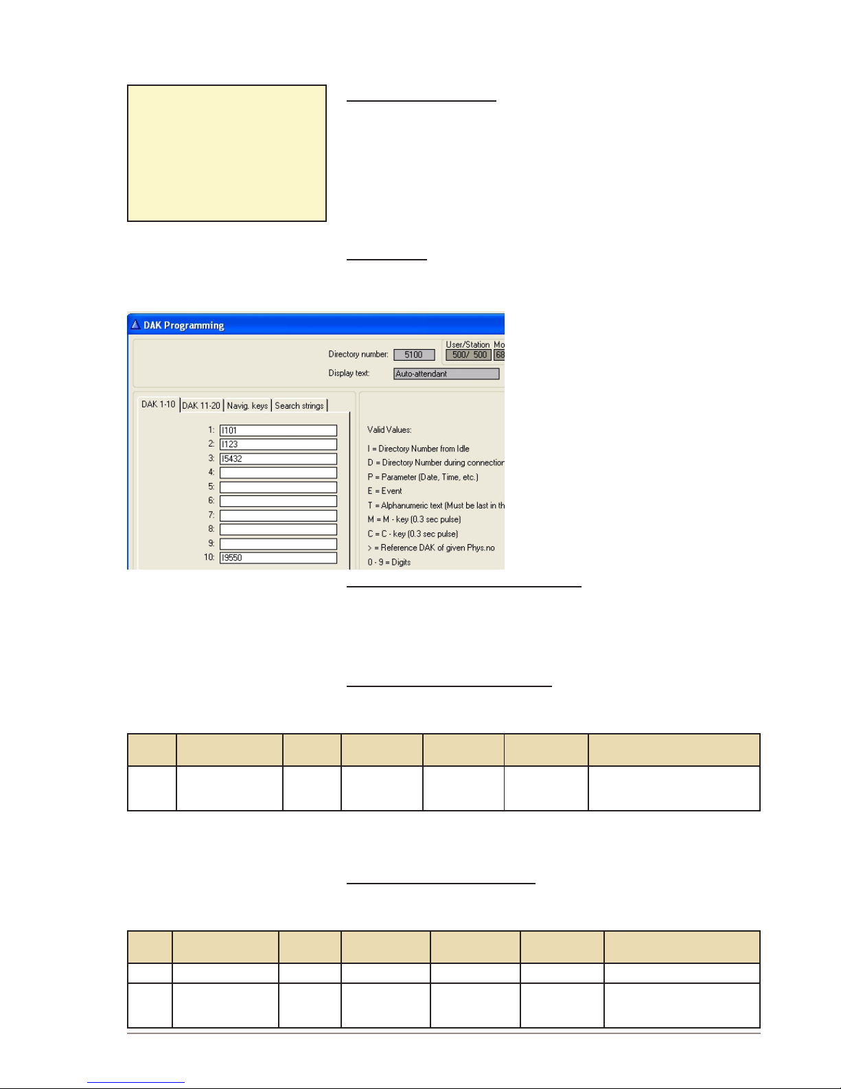
55
AlphaCom XE - Installation, Conguration & Operation
A100K10805
9.4.1 Conguration
The default directory number for the auto-attendant feature is 9550.
Recording the message
● Dial 8180 + 9550 from a Super User station.
- Press and hold the M-key while recording.
● Release the M-key to listen to the message
- Press 8 to save, or
- Press the M-key again to make a new recording
Alternatively, a WAV le can be uploaded from the web interface,
AlphaWeb as described in section 9.2.1.
Digit routing
The Auto-attendant number 9550 uses the DAK table of physical station
500 for the “digit” actions.
● In the Users & Stations window in
AlphaPro, select physical number
500 in the list box and click DAK
● In the DAK table, enter the call
destination for digit 1 to 9 (DAK 1-9),
and digit 0 (DAK 10)
If the caller doesn’t press any
numbers within 5 seconds, the call is
automatically routed to the entry in
Search String 1.
In the Auto-attendant digit routing
example shown, Digit 1 calls station
101, digit 2 calls station 123, digit 3 calls
station 5432, and digit 0 repeats the
voice menu
Adding more auto-attendant numbers
Up to 3 auto-attendant numbers are supported, depending on the
license installed. Directory numbers for the rst auto-attendant is
included by default. For the second and third auto-attendants, you have
to add new directory numbers from AlphaPro.
Adding a second auto-attendant:
In Directory & Features, click Insert and add a new number with the
following properties:
Dir.
no.
Display Text Feature Parameter 1
(User no.)
Parameter 2 Parameter 3 Description
9551 AutoAttendant2 105 0 2 501
Auto-attendant number 2, using
Stored Voice Message 2 and the DAK
table of physical number 501
● To record a message, dial 8180 + 9551 + M-key.
Digit routing is done in the DAK table of physical number 501.
Adding a third auto-attendant:
● In Directory & Features, click Insert and add two new numbers with
the following properties:
Dir.
no.
Display Text Feature Parameter 1
(User no.)
Parameter 2 Parameter 3 Description
8183 MenuMsg3 111 11 3 0
Stored Voice Message 3
9552 AutoAttendant3 105 0 3 502
Auto-attendant number 3, using
Stored Voice Message 3, and the
DAK table of physical number 502
Example:
”Welcome to Procom Ltd.
Press 1 for switchboard,
press 2 for Sales department,
press 3 for Marketing
department,
or wait for an answer”
Page 56

56
A100K10805
AlphaCom XE - Installation, Conguration & Operation
● To record a message, dial 8180 + 9552 + M-key
Digit routing is done in the DAK table of physical number 502.
9.4.2 Hardware and license requirements
● Hardware: The auto-attendant feature requires AMC-IP hardware
version 8000/5 or 8000/6 (Black PCB).
● License: Auto-attendant requires a Basic (1 auto-attendant) or
Enhanced (3 auto-attendants) Audio Messaging license.
Page 57
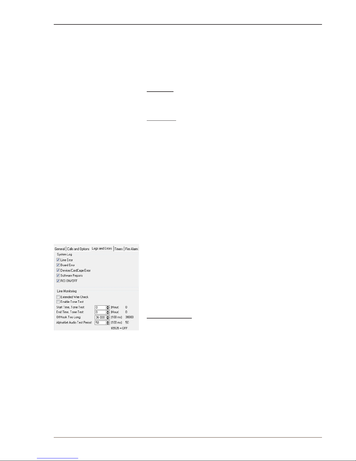
57
AlphaCom XE - Installation, Conguration & Operation
A100K10805
10 System Monitoring
10.1 System Logging
The AlphaCom XE provides three types of logs.
● Debugging log
● System log
● Call statistics
Debug log
The debugging log includes low level system events that STENTOFON
software engineers and support personnel use for troubleshooting.
System log
The system log provides technical events for monitoring the health of
the AlphaCom system. The system log includes the following type of
events:
● Board down
● Line error
● Device/card cage error
● AGA/AE1 line error
● System report
● Remote input on/off
● Customized event logging
In AlphaPro, it is possible to congure the events that should be
included in the system log.
● Click the Exchange & System icon
● Click System
● Select Logs and Errors
● Select the events you want to be reported
● Conrm by clicking OK
It is also possible to congure customized events in the system log. This
is done in AlphaPro by using Event programming.
Call statistics log
The call statistics log provides an event for each call in AlphaCom XE.
The format of the call events are (valid from AMC SW 10.60):
Call ID ; Sec ; Call State ; From Node ; From DirNo ;
From DispText ; To Node ; To DirNo (Collected digit
SIP) ; To DispText ; Codec/rtp info
Open Call example:
The call has been in private ringing for 5 seconds, then 3 seconds of
conversation.
000008 ; 5 ; Call Open ; Lab(11) ; 151 ; IP Station ;
Oslo(3) ; 2561 ; John Brown ;
000008 ; 3 ; Call Open End ; Lab(11) ; 151 ; IP Station ;
Oslo(3) ; 2561 ; John Brown ; g722 g722
Page 58
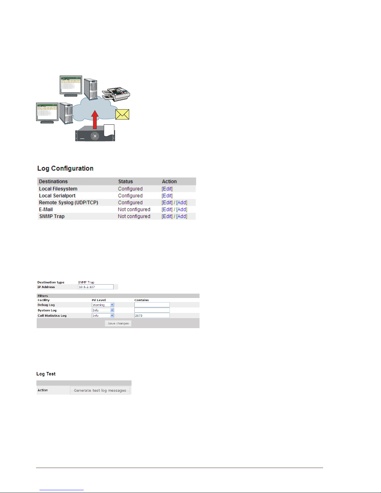
58
A100K10805
AlphaCom XE - Installation, Conguration & Operation
AlphaCom XE can have many log destinations, allowing it to output
emergency events to a specic destination and all information events to
another.
For each log destination, it is possible to set up the type of log events
(debugging log events, system log events, call statistics events) with
priority level to be logged. In addition, it is possible to have a text lter to
only output events containing a certain text string like ALARM.
The types of log destinations supported by AlphaCom XE are:
- SNMP trap
- Syslog server
- E-mail
- Local le
- Printer
- Console
AlphaWeb is used to congure and set up the log destinations. Log into
AlphaWeb:
● Select SystemConguration> Logging
- The list shows the log destinations and current conguration status.
● The conguration may be altered as follows:
- Click [Edit] to congure the destination
- Click [Del] to delete the option
- Click [Add] to create an additional item of the same type
(e.g. two e-mail addresses)
● To congure, click [Edit] and ll in the dialogue box according to
destination type.
● In the Pri Level drop-down list, select the lowest priority level for the
different logs you want sent to the destination.
● Optional: Include a text lter to output events only containing a
certain text string, e.g. ALARM
● Click Save changes
● Click Generate test log messages to test the log transmission
10.1.1 LocallogleandAlphaWeb
AlphaWeb provides access to the local log le on AlphaCom. The
following functions are provided via AlphaWeb:
● View Log
● Search Log
● Retrieve Log
Syslog server
SNMP server
Printer
E-mail
AlphaCom XE7
Local
file
Page 59
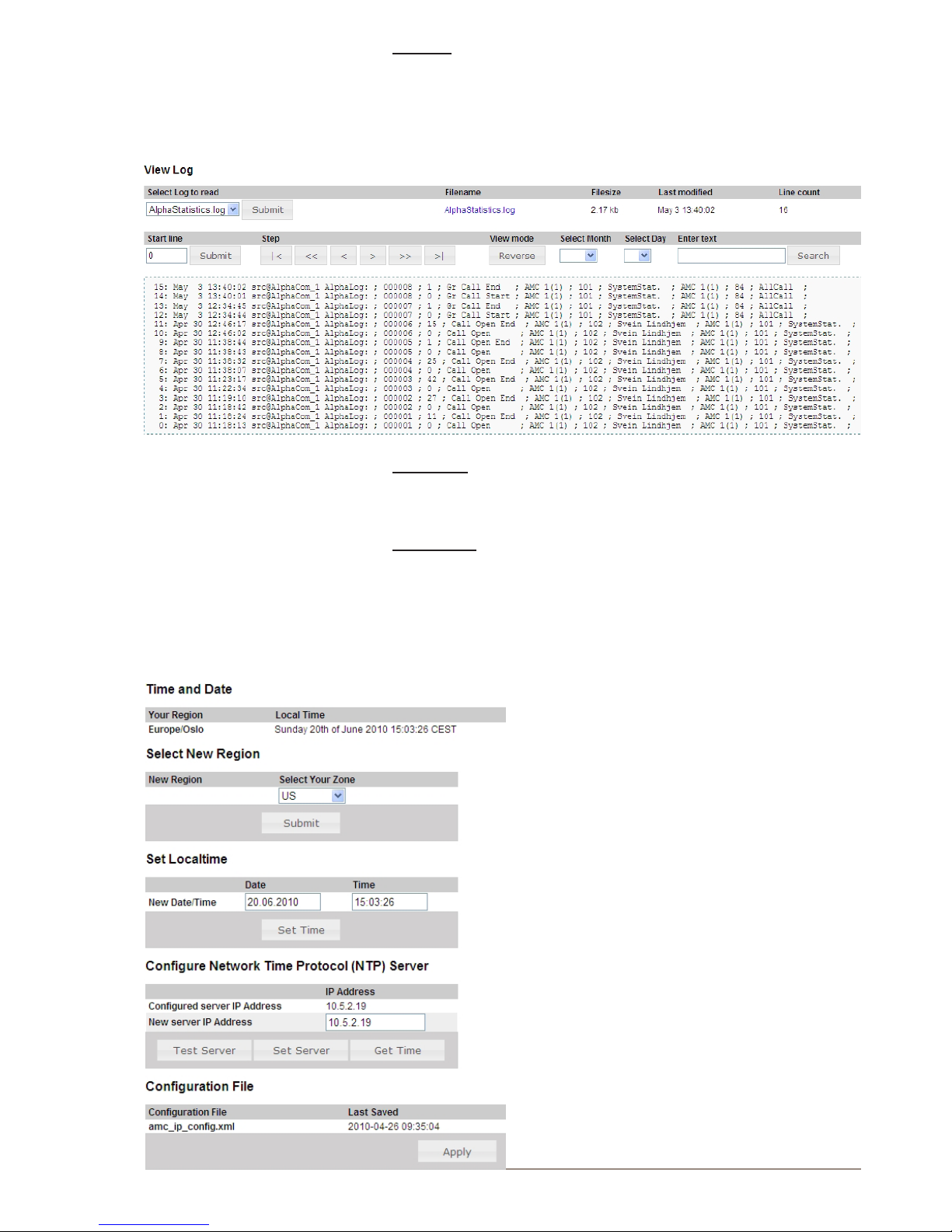
59
AlphaCom XE - Installation, Conguration & Operation
A100K10805
View log
● Log in to AlphaWeb
● Select System Monitoring > Logging
● Select the log le to read
● Click Submit
Search log
To view a log, search the log by stepping through the log, or by date or
text string search.
Retrieve log
When viewing the log, the hyperlink for the log le name may be
selected to download the log to your PC.
10.1.2 System clock and event time stamps
To congure the system clock and event time stamps:
● Log in to AlphaWeb
● Select SystemConguration>
Time and Date
● Select the time zone from the Select
Your Zone drop-down list
● Set the local time by entering values
in the Date and Time elds, or
enter the IP address to a Network
Time Server in the New server IP
Address eld
● Click Apply to save changes
Page 60
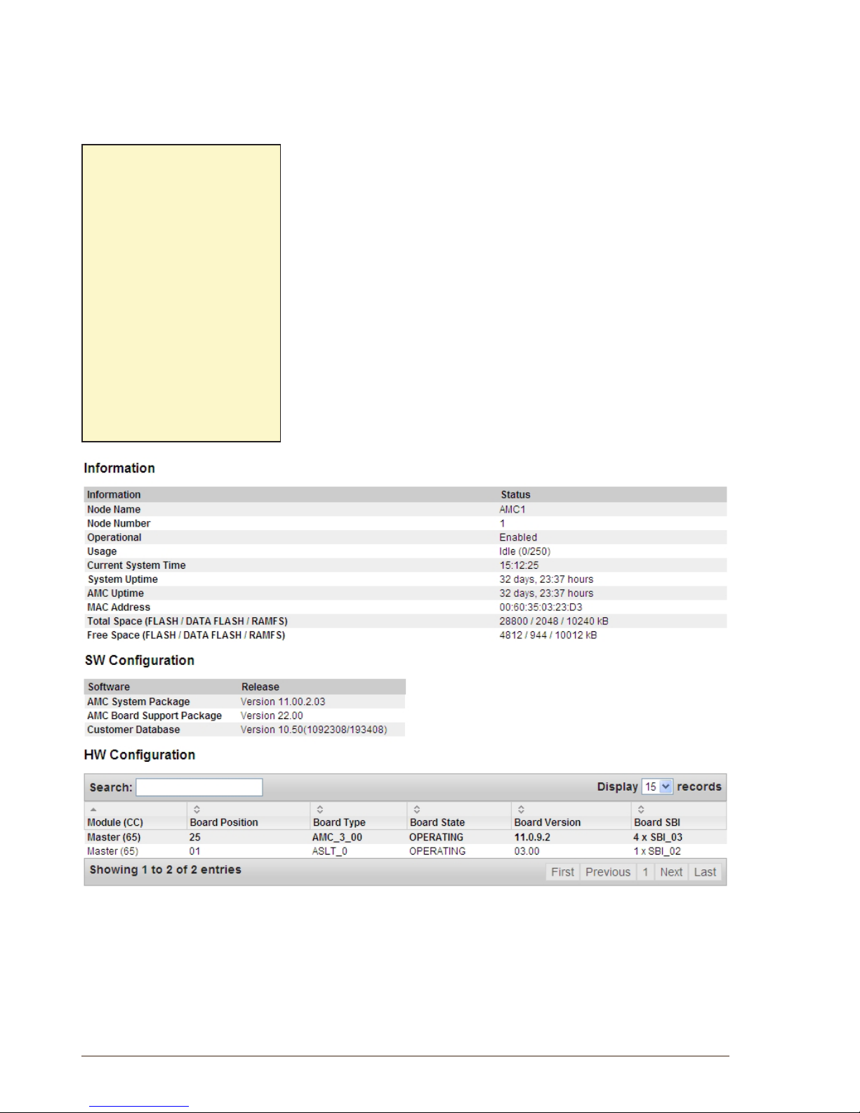
60
A100K10805
AlphaCom XE - Installation, Conguration & Operation
10.2 System Information and Statistics
AlphaCom XE provides access to important system status information
and statistics from:
- SNMP MIBs
- AlphaWeb
10.2.1 SNMP MIBs
AlphaCom XE support SNMP traps and SNMP MIB interface according
to IETF standards. AlphaCom XE supports two MIBs. These are:
- SNMP MIB II
- SNMP AlphaCom MIB
The AlphaCom MIB includes information such as node status
information and VoIP statistics. For a complete denition of the
AlphaCom MIB, see the document STENTOFON AlphaCom MIB.
10.2.2 System information
AlphaWeb provides access to system status information and statistics.
● Log in to AlphaWeb
● Select System Monitoring > Node Information
● Click Information to see general system information, and SW and
HW conguration
● Click Processes to see software state and versions
SNMPdenition:
Simple Network Management Protocol
(SNMP) is a set of protocols for
centralizing the management of IP
networks.
It is used for both collecting
information from and conguring the
full range of network devices, including
servers, printers, switches, hubs,
routers, rewalls, wireless access
points and individual workstations.
A wide variety of information can be
collected, ranging from a server’s CPU
usage level to its chassis temperature.
An SNMP device structures its
records in a set of MIBs (Managed
Information Base), where the SNMP
MIB II includes information such as
the node’s CPU and memory status,
active tasks, etc.
Page 61
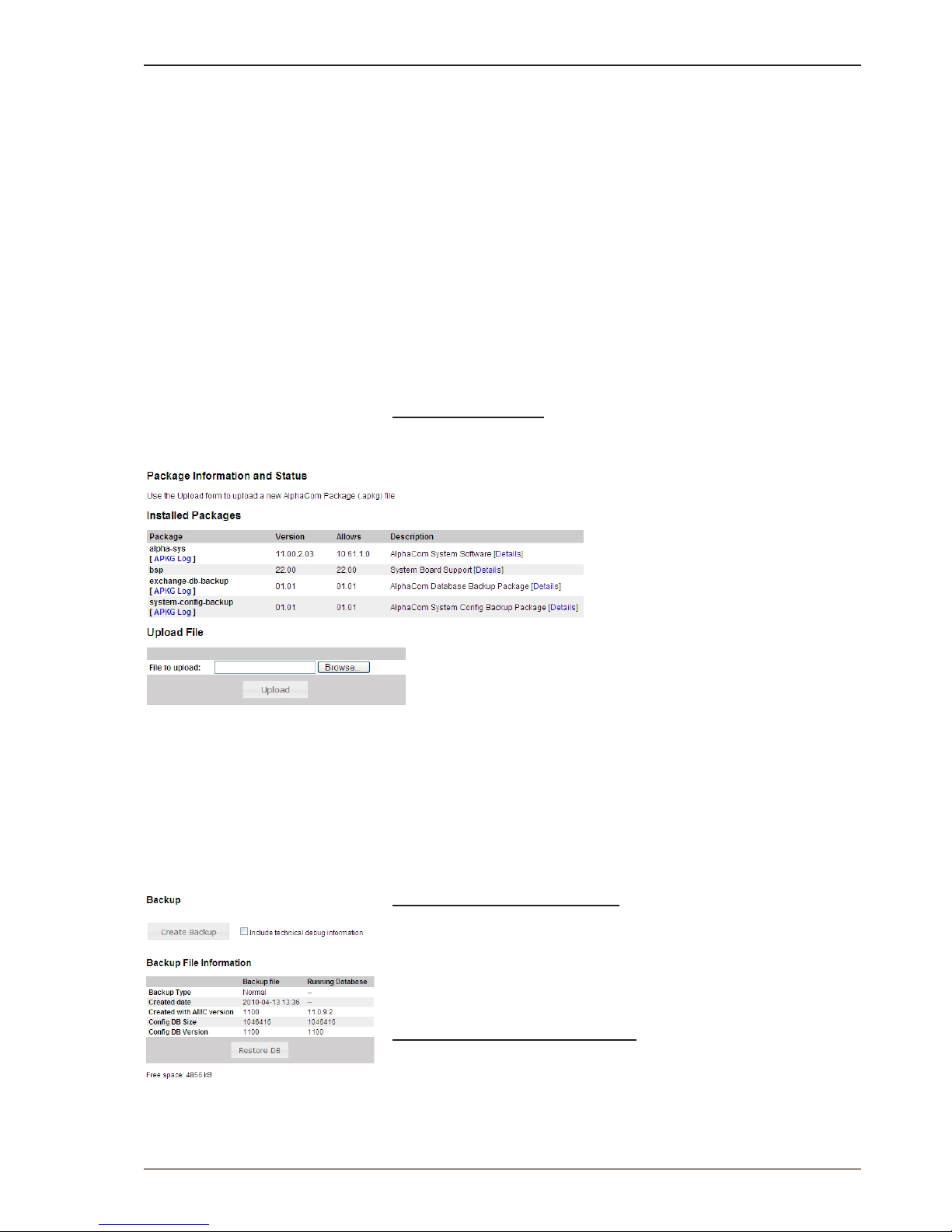
61
AlphaCom XE - Installation, Conguration & Operation
A100K10805
11 Upgrade & Backup
It is necessary to make a backup of the client data from AlphaPro before
upgrading the software. This is performed by selecting GetAll from
AlphaPro and storing the backup on the PC.
The backup from AlphaWeb or station can not be stored and retrieved
from the AMC-IP’s ash memory if the NVRAM or SW is upgraded to
a newer version. AMC-IP will perform an automatic cold start and load
default numbers, etc.
Backup from AlphaWeb or station (7820) is only possible if the client
data is to be loaded back to the same NVRAM and SW versions.
11.1 Software Upgrade
AlphaCom has one AMC (AlphaCom Module Controller) system
software package. This package is named:
alpha_sys_aa_bb_cc_dd.apkg
where aa_bb_cc_dd is the version number.
AMC System upgrade
To upgrade the AMC system package:
● Log in to AlphaWeb
● Select System Maintenance >
System Upgrade
● Click Browse to select the
appropriate .apkg le
● Click Upload to transfer the AMC
system package to AlphaCom
● Click Install to start the installation
L AlphaCom XE will do an MD5
check to verify that the software
package is valid. The MD5 digital
signature is used to hinder possible
virus infections.
11.2 CongurationBackupandRestore
AlphaWeb provides an easy way to back up and restore the running
conguration in the AlphaCom XE.
The procedure will perform a backup of the server database to the PC
as an .apkgs le. Previous versions will be overwritten.
Use the System Upgrade menu to restore the .apkgs le
Backup of running conguration
● Log in to AlphaWeb
● Select System Maintenance > Backup
● Click Create Backup
● Click the link backup.bin to download the backup le to your PC
Restore conguration from backup
● Log in to AlphaWeb
● Select System Maintenance > System Upgrade
● Click Browse to select the appropriate .apkgs le in the PC
● Click Upload
Page 62

62
A100K10805
AlphaCom XE - Installation, Conguration & Operation
12 Appendix - Technical Data
12.1 Specications
AlphaCom Server
Conditions XE1 XE7 XE20 XE26
Dimensions, mm
(W x H x D)
Rack mount 332x44x340 427x133x380 483x265x365 483x841x365
Floor cabinet - - - 483x841x513
w. distribution eld - - - 483x841x593
Weight, Kg Rack mount 2.0 7.0 17.0 39.0
Floor cabinet - - - 46.0
w. distribution eld - - - 53.5
Mounting 19” rack Wall, shelf
or 19” rack
19” rack Floor cabinet
or 19” rack
Input voltage 5 VDC 24 VAC +/- 10%
or 20 - 32 VDC
90 - 270 VAC 90 - 270 VAC
or 20 - 60 VDC
Power consumption, W Fully equipped 4 260 max. 450
(80 subscribers)
580 max.
Temperature Environment -5 to +55
O
C - Recommended +20OC
Humidity range Non condensing 10% to 90% RH
Feature cards Slot positions 0 6 18 24
Traditional intercom Extensions, max. 0 36 80
(102 physically)
138
Entertainment channels On APC board NA 2 6 6
Per AGA board NA 6 16 16
Remote control outputs Per ASLT board NA 6,
12 on back plane
6 6
Remote control inputs On APC board NA 2 6 6
Serial port COM0 RS232, 9-pin D-sub RS232, RJ45
COM1, RJ45 RS232/422/485
Ethernet 2 x RJ45 10/100 Mbps
Trafc capacity SIP trunks 30 channels
VoIP AlphaNet 30 channels
Digital trunks 32 channels
Analog trunks 6 channels
IP protocols IP v4/v6 - TCP - UDP - Telnet - FTP - NTP - HTTP1.1 - Syslog - SNMP v2c - SIP - RTP -
RTCP -VoIP AlphaNet - STENTOFON data
Audio technology High-Resolution 1-Bit Audio - High-Fidelity 40 Hz-18.5 kHz - Wideband 7 kHz (G.722) -
Narrowband 3.4 (G.711) - Adaptive Jitter Buffers - Adaptive Time Synchronization
EMC Emission EN 61000-6-3 and EN61000-6-4
EN 55022 (1994) + A1 (1995) + A2 (1997)
Immunity EN 61000-6-1 and EN 61000-6-2
EN 55024 (1998) + A1 (2001) + A2 (2003)
Safety / Approval CE
FCC part 15
CE
EN 60950
CE
EN 60950
CE
EN 60950
L For more details on each AlphaCom XE server, see individual datasheets.
Page 63

63
AlphaCom XE - Installation, Conguration & Operation
A100K10805
12.2 Physical Numbers
Each subscriber point in an AlphaCom XE server has a physical
number. The number is determined by the board position and the type of
module (master/slave).
There are 6 subscribers on each board of the Intercom board ASLT,
Telephone board ATLB, and AGA board.
- Board in slot 1 has physical numbers 1-6
- Board in slot 2 has physical numbers 7-12
- Board in slot 3 has physical numbers 13-18, and so on.
Telephone board ATLB-12 has 12 subscribers on each board. The 6 rst
lines have physical numbers according to the insertion slot, while the 6
last lines have numbers with an offset of 276 to the 6 rst numbers.
- Board in slot 1 has physical numbers 1-6 and 277-282
- Board in slot 2 has physical numbers 7-12 and 283-288
- Board in slot 3 has physical numbers 13-18 and 289-294, and so
on.
Since card positions 2-7 are not used in XE20, the corresponding
physical numbers are therefore missing.
PHYSICAL NUMBER TABLE
AlphaCom modules XE7 XE20 XE26
Single or master
1 - 36 1 - 6
143 - 138
1 - 138
1
st
slave
139 - 174 139 - 144
187 - 276
139 - 276
2
nd
slave
277 - 313 277 - 282
325 - 414
277 - 414
3
rd
slave
415 - 451 415 - 421
510 - 552
415 - 552
12.3 ASLT & AGA Board Positions
Board positions and physical
numbers in AlphaCom XE7
Board positions and physical
numbers in AlphaCom XE20
AMC
36
31
1
P5
P6
N1
N5
N4
N2
N3
24V DC
Out
24V AC In
+
24V DC
In
+
_
_
Program level
RCO 1 - 6
1
RCO 7 - 12
Prog. 6
Prog. 5
RCI 2
RCI 1
Ethernet 0 Ethernet 1
Serial Port 0
Serial Port 1
USB
485 422
1
12
6
18
24
30
7
13
19
25
7
6
5
4
3
2
1
ASLT, ATLB, AGA
ACGND
DCGND
APC
AMC
AGA
AGA
INTERNAL
DC POWER
POWER OUT
26 25 24 23 22 21 20 19 18 17 16 15 14 13 12 11 10
9 8 1
AS LT
AGA possible
MAINS
FUSES
NC
+24V
+15V
+ 5V
0V
Page 64
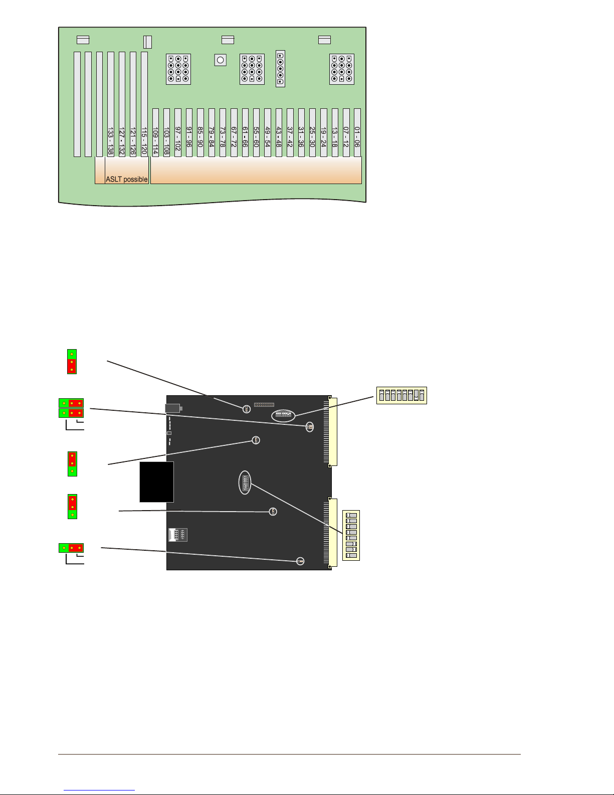
64
A100K10805
AlphaCom XE - Installation, Conguration & Operation
Board positions and physical
numbers in AlphaCom XE26
12.4 Switches and Jumpers
12.4.1 AMC-IP
The AMC-IP version 11 board has two 8-bank DIP switches and four
jumpers set to default positions at delivery.
L Do NOT change the default settings unless you are absolutely
sure of the consequences!
AMC-IP v.11 BOARD
Hot-Plug
Board
status
Cold boot
Ethernet
status
STIC card
1
2
3
3
2
1
3
2
1
Disabled
Enabled
Watchdog
1 2 3
1 2 3
Not terminated
Terminated
RS422 Termination
Expansion Bus Clock
MBI Master Enable
Master Request
16 MHz
33 Mhz
APC Controlled
Disabled
Master Board
Stand-by Board
1 8
ON
1
8
NO
S200 - Ethernet settings
1 - Port 1 = Auto Negotiation enable
2 - Port 0 = Auto Negotiation enable
3 - Port 1, Speed = 100 Mbps OFF = 10 Mbps
4 - Port 0, Speed = 100 Mbps OFF = 10 Mbps
5 - Port 1, Duplex = full OFF = half
6 - Port 0, Duplex = full OFF = half
7 - Ethernet LED configuration, bit 0
8 - Ethernet LED configuration, bit 1
ON
ON
ON
ON
ON
ON
OFF
ON
S601 - System settings
1 - Linux Console enable
2 - Self test
3 - Reserved
4 - Reserved
5 - PCI Clock select = 66 MHz
6 - PCI Arbiter OFF = enabled
7 - PCI Host OFF = enabled
8 - Serial port 1 = RS232
ON /
ON /
ON = 33 MHz
= disabled
= disabled
ON = RS422
OFF
OFF
ON
ON
OFF
OFF
S700
S200
S605/6
S600
S601
S900
S901
Default
Default
APC
AMC
AGA
AGA
FAN 1 FAN 2
FAN 3
LED
POWER
SUPPLY 2
POWER
SUPPLY 1
POWER
SUPPLY 3
POWER
OUT
GND
wrist strap
26 25 24 23 22 21 20 19 18 17 16 15 14 13 12 11 10
9 8 7 6 5 4 3 2 1
AS LT
AGA possible (cut upper plastic on back-wiring connector)
Page 65
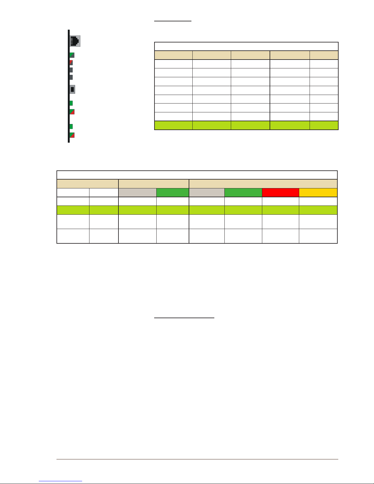
65
AlphaCom XE - Installation, Conguration & Operation
A100K10805
S200 settings
The switch S200 determines the Ethernet port speed, the duplex mode,
and the link status LED mode.
SPEED / DUPLEX
S200-1/2 S200-3/4 S200-5/6 Speed Duplex*
OFF OFF OFF 10 Mbps Half
OFF OFF ON 10 Mbps Full
OFF ON OFF 100 Mbps Half
OFF ON ON 100 Mbps Full
ON OFF OFF Auto Half
ON OFF ON 10 Mbps Auto
ON ON OFF 100 Mbps Auto
ON ON ON Auto Auto
* Full = Open duplex (telephone)
Half = Voice controlled duplex
Auto = Automatically sensed
LINK STATUS FOR ETHERNET PORT 0 AND 1
S200 Link LED Dual LED
7 8 Off Green Off Green Red Amber
OFF OFF !0 Mbps 100 Mbps Link down Half Duplex Error Full Duplex
OFF ON Link down Link up No activity Rx activity Tx activity Tx+Rx act.
ON OFF 10 Mbps 100 Mbps Link down
Link up,
Activity*
Full Duplex,
Collisions*
Link up in
full Duplex
ON ON 10 Mbps 100 Mbps Link down
Link up,
MII isolation*
Full Duplex,
Collisions*
Link up in
full Duplex
* Blink rate = 100 ms
12.5 Port Pin-Out
The AlphaCom XE servers have two serial and two Ethernet ports.
AlphaCom XE20/XE26
For AlphaCom XE20 and XE26, the serial ports are available as RJ45
connectors on the AMC-IP Filter Card.
● Serial Port 0 is set to RS232 only.
● Serial Port 1 is set to RS232 by default, but can be set to RS422 or
RS485.
- To set Serial Port 1 to RS422, set DIP switch S601-8 on the AMCIP board to the ON position (see gure on page 64).
- To set Serial Port 1 to RS485, set DIP switch S601-8 on the AMCIP board to the ON postion, as well as move the two jumpers on the
AMC-IP Filter Card to the “RS485” position.
Eth 1
Eth 0
Link LED
Link LED
Dual LED
Dual LED
~
AMC IP11 board
Page 66
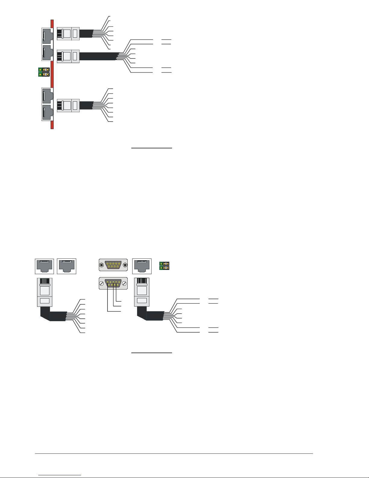
66
A100K10805
AlphaCom XE - Installation, Conguration & Operation
1
1
1
1
RS485
RS422
8
8
8
8
Serial ports
Ethernet ports
0
0
1
1
1
8
Rx
Gnd
Gnd
Tx
RS232
Serial Port 0
Serial Port 1
1
8
1
8
RS232
RS485
RS422
-
Rx
Gnd
Gnd
Tx
1
8
A
B
A
B
Tx-
Tx+
Eth_Tx +
Eth_Tx -
Eth_Rx
+
Ref
Ref
Eth_Rx
-
Ref
Ref
8
7
6
5
4
3
2
1
8
7
6
5
4
3
2
1
6
5
4
3
Rx
-
Rx+
AMC Filter Card for XE20-26
AlphaCom XE7
For AlphaCom XE7, Serial Port 0 is on a 9-pin D-SUB connector and
Serial Port 1 is on an RJ45 connector. These connectors are found on
the AlphaCom XE7 backplane.
● Serial Port 0 is set to RS232 only.
● Serial Port 1 is set to RS232 by default, but can be set to RS422 or
RS485.
- To set Serial Port 1 to RS422, set DIP switch S601-8 on the AMCIP board to the ON position (see gure on page 64).
- To set Serial Port 1 to RS485, set DIP switch S601-8 on the AMCIP board to the ON postion, as well as move the two jumpers on the
AlphaCom XE7 backplane to the “RS485” position.
1 1 1
8 8 8
Eth_Tx +
Eth_Tx -
Eth_Rx
+
Ref
Ref
Eth_Rx
-
Ref
Ref
1 8
1 8
RS232
1
1 1
Serial ports
1 8
1 8
1
1
5
5
6
6
9
9
Ethernet ports
0
0
1
1
Tx
Rx
Gnd
RS4
22
RS485
RS232
RS485
RS422
-
Rx
Gnd
Gnd
Tx
A
B
A
B
Tx-
Tx+
8
7
6
5
4
3
2
1
8
7
6
5
4
3
2
1
2
3
5
Rx
-
Rx+
AMC XE7
AlphaCom XE1
The connections and pinouts are identical to that of AlphaCom XE7.
The Ethernet and serial ports are located at the rear of the cabinet.
● Serial Port 0 is set to RS232 only.
● Serial Port 1 is set to RS232 by default, but can be set to RS422 or
RS485.
- To set Serial Port 1 to RS422, set DIP switch S601-8 on the AMCIP board to the ON position (see gure on page 64).
- To set Serial Port 1 to RS485, set DIP switch S601-8 on the AMCIP board to the ON postion, as well as move the two jumpers JP2
and JP3 on the AlphaCom XE1 motherboard to the position 2-3. To
get access to the jumpers, you must remove the top cover of the
XE1 server.
Page 67
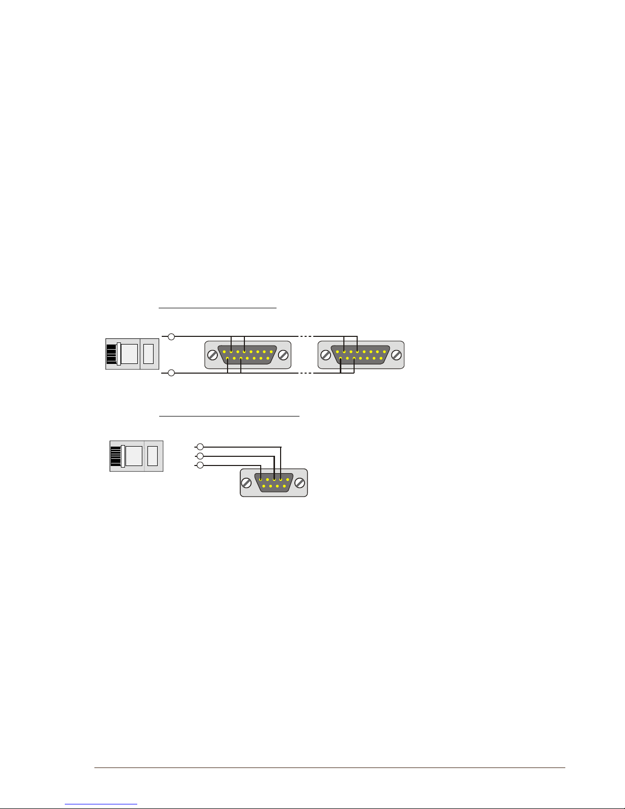
67
AlphaCom XE - Installation, Conguration & Operation
A100K10805
12.5.1 RIO controller unit connection
The signal to and from AlphaCom XE is taken from the RJ45 serial port
1, i.e. pins 1 and 2 if RS485 is used or pins 3 and 6 if RS232 is used. In
the 15-pin D-SUB for the RIO Controller Unit, the pins 2 & 4 and 9 & 11
must be connected together.
The GND connection between AlphaCom and RIO in RS485 mode is
normally not necessary. In general on RS485 links, the connection of
a third wire (GND) between the source and receiver may be done to
limit the common mode voltage that can be impressed on the receiver
inputs. If you want to connect it, use pin 5 on the AlphaCom RJ45 port
to pin 5 on the RIO 15-pin D-SUB. Programming is the same as with
conventional AMC.
L Note that when using RS485, the switch S601-8 on the AMC-IP
board must be set to the RS422 positon, and two jumpers must
be moved from the RS422 to RS485 position. The jumpers are
located on the AMC-IP Filter Card for XE20 and XE26, and on the
backplane of the XE7. On the XE1 you need to open the cover to
access the jumpers.
1
5
6
9
1
1
8
8
15
15
9 9
1
8
Serial Port 1
1
2
RJ45
15-pin D-SUB 15-pin D-SUB
RIO #1
RIO #n
AlphaCom
Point-To-Point RS232 Cabling
1
8
Serial Port 1
RJ45
9-pin D-SUB
RIO
AlphaCom
3 (TX)
6 (RX)
5 (GND)
Multidrop RS485 Cabling
Page 68

www.zenitel.com
Zenitel Norway AS
P.O. Box 4498 Nydalen
NO-0403 OSLO
Norway
DOC NO.
Zenitel and its subsidiaries assume no responsibility for any errors that may appear in this publication, or for damages arising from the information therein. STENTOFON and VINGTOR products are developed and
marketed by Zenitel. The company’s Quality Assurance System is certified to meet the requirements in NS-EN ISO 9001. Zenitel reserves the right to modify designs and alter specifications without notice.
ZENITEL PROPRIETARY. This document and its supplementing elements, contain Zenitel or third party information which is proprietary and confidential. Any disclosure, copying, distribution or use is prohibited, if not
otherwise explicitly agreed in writing with Zenitel. Any authorized reproduction, in part or in whole, must include this legend. Zenitel – All rights reserved.
A100K10805
 Loading...