

Vingtor VSP 12 Way, VSP-211-L, VSP-213-L, VSP-223-L, VSP-122 Technical Manual
...
TECHNICAL MANUAL
Amplified Batteryless Telephone System
VSP 12 Way
A100K10873

2
A100K10873
VSP 12 Way Batteryless Telephone System
Technical Manual
Zenitel Norway AS and its subsidiaries assume no responsibilities for any errors that may appear in this
publication nor for damages arising from the information in it. No information in this publication should be
regarded as a warranty made by Zenitel Norway AS.
The information in this publication may be updated or changed without notice. Product names mentioned in
this publication may be trademarks and are used only for purposes of identication.
Zenitel Norway AS ©2011
About this Document
Document Scope
This document is intended for qualied technicians who will install and
service the VSP 12 Way Amplied Batteryless Telephone System on
marine vessels.
The document provides relevant information on system features,
available equipment, typical congurations, simplied wiring and
programming, and technical data for the system.
Interconnection procedures, hardware requirement and special terminal
programming for conguration are also described.
The following station models (version 6.0) are available for the VSP 12
Way system:
Product Part Number
Main Station, panel mounted VSP-211-L
Main Station, panel mounted with relay circuit VSP-223-L
Main Station, watertight VSP-122
Main Station, portable, watertight VSP-122P
Main Station, panel mounted, indoor unit VSP-213-L
Publication Log
Rev. Date Author Comments
4.0 2008-04-23 Published
5.0 2009-08-24 SEN/JF
New circuit board
Some contents updates
New document layout
5.1 18-05-2010 HKL Complete DIP switch settings
5.5 30-08-2010 ER
New front and back page.
Doc. no. VSP-12 Way_is is
replaced by A100K10873
6.0 22-7-2011 HKL
Version 6.0 station models,
revised block diagram
6.1 16-5-2012 HKL Revised block diagram
Related Documentation
For further information about the VSP Amplied Batteryless
Telephone System not covered by this manual, refer to the following
documentation:
Doc. no. Subject Documentation
A100K10675 VSP 12 Way Amplied Batteryless Telephones Getting Started Guide
A100K10758 VSP-M Amplied Batteryless Telephones Technical Manual
VSP-Ex_iu Intrinsically Safe Set for VSP
VSP-5012 Buffer unit & VSP-512 Main station
Installation & User
Manual

3
VSP 12 Way Batteryless Telephone System
Technical Manual
A100K10873
Contents
1 General Description ........................................................................................................ 4
1.1 System ...................................................................................................................4
1.2 Station Types ..........................................................................................................5
2 Functional Description ................................................................................................... 6
2.1 Power .....................................................................................................................6
2.2 Calling ....................................................................................................................6
2.3 Amplier .................................................................................................................7
2.4 Call Signal ..............................................................................................................7
2.4.1 Stations for Use in Safe Areas .........................................................................7
2.4.2 Stations for Use in Hazardous Areas ...............................................................7
2.5 Handset .................................................................................................................. 7
3 Installation ....................................................................................................................... 8
3.1 Connection .............................................................................................................8
3.2 Cabling ...................................................................................................................8
3.3 Compass Safety ...................................................................................................10
3.4 Setting Extension Number ....................................................................................10
4 Operation ....................................................................................................................... 11
5 Troubleshooting ............................................................................................................12
5.1 Conversation Lines ...............................................................................................12
5.2 Call Tone...............................................................................................................12
6 Specications................................................................................................................13
6.1 Electrical Specications ........................................................................................13
6.2 Certicates ...........................................................................................................13
7 DIP Switch Settings for Extension Numbers ..............................................................15
8 Station & Mounting Dimensions..................................................................................16
8.1 VSP-122 ............................................................................................................... 16
8.2 VSP-122P .............................................................................................................17
8.3 VSP-211-L ............................................................................................................18
8.4 VSP-213-L ............................................................................................................18
8.5 VSP-223-L ............................................................................................................19
Figures
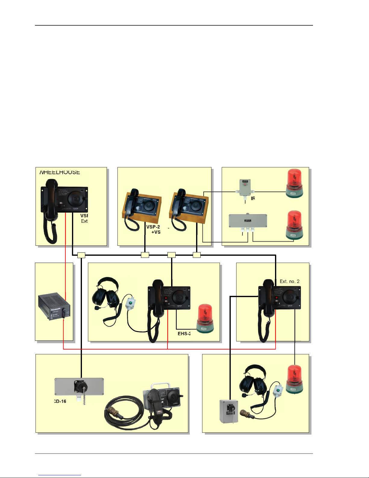
Figure 1: System Conguration Example.................................................................................................................... 4
Figure 2: Main station VSP-211-L principle diagram ................................................................................................... 6
Figure 3: Cabling diagram based on system conguration example .......................................................................... 9
Figure 4: DIP switch setting for extension no. 2 ........................................................................................................ 10
Figure 5: Extension number label ............................................................................................................................. 10
4
A100K10873
VSP 12 Way Batteryless Telephone System
Technical Manual
1 General Description
1.1 System
The VSP Amplied Batteryless Telephone System is designed for
safe, loud and clear communication, and as a replacement for the
conventional Sound Powered Telephones.
The conventional facilities are retained and a low power consumption
amplier with capacitor-battery ensures excellent communication.
Through the use of dynamic microphone- and receiver-inserts, speech
and hearing levels that are 4 times louder can be obtained as compared
to the Sound Powered Telephones.
The VSP system is independent of the vessel’s power supply and fullls
the demands for emergency communication between vital locations
onboard.
The VSP system described in this manual is a system comprising up to
12 main stations with selector switches for selective calling between all
connected stations. The VSP system can also be connected to a 24V
DC power supply and work as a Common Battery Telephone System.
Figure 1: System Conguration Example
WHEELHOUSE CORRIDOR
VSP-211-L
ACCOMMODATIONS
VSP-213-L
+VSPK
VSP-223-L
IRR-24
IRR-220
ENGINE ROOM
EHS-24
EHS-24
EHS-220
EHS-24
VSP-36-PEL
VSP-36-PELP
STEERING GEAR
ENGINE
CONTROL
ROOM
CD-4
24 VDC
VSP-223-L
Subscriber lines
Ext. no. 1
Ext. no. 4 Ext. no. 5
Ext. no. 2
Ext. no. 3
(Ext. no. 2)
CAPTAIN'S CABIN
CHIEF ENG. CABIN
OPEN DECK
220 VAC
24 VDC
CD-16
VSP-122P
Ext. no. 6
5
VSP 12 Way Batteryless Telephone System
Technical Manual
A100K10873
1.2 Station Types
The VSP 12 Way system is a range of stations with up to 12 extensions
designed to provide clear and secure communication in any area and
under all conditions on board a vessel or rig. The various station types
can be mounted to suit particular onboard environments.
Mounting Environments
Flush or panel Bridge and Control Rooms
Desktop Accommodations
Light wall Noisy areas
Bulkhead Deck areas, Hazardous areas
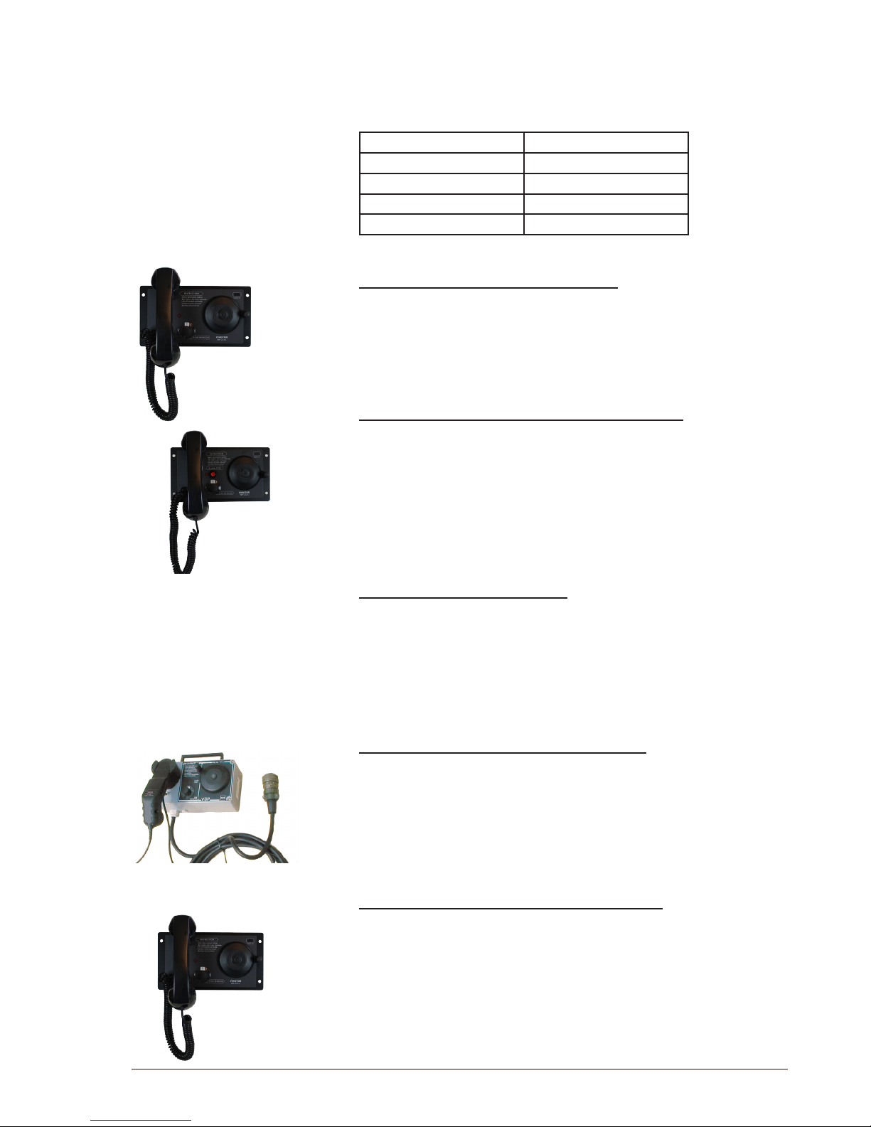
The following station types are version 6.0 models.
VSP-211-L Main Station, panel mounted
● Main station with built-in amplier
● Bulkhead mount in on-wall back-box MBOKS
● Suitable for weelhouse and control room
VSP-223-L Main Station, panel mounted with relay
● Alarm stop button
● Noise compensated microphone
● LED call indicator
● Bulkhead mount in on-wall back-box MBOKS
● Suitable for control room and noisy areas
VSP-122 Main Station, watertight
● Main station in watertight housing
● Water resistant mil.spec. handset
● Bulkhead mount
● Suitable for bridge wings and open deck areas
VSP-122P Main Station, portable, watertight
● Main station in watertight housing
● Water resistant military spec. handset
● Portable with handle and 5 or 10 m cable
● Suitable for bridge wings and open deck areas with plug box CD-16
VSP-213-L Main Station, panel mounted indoor
● Desk or wall mount in wooden cabinet VSPK
● Bulkhead mount in on-wall back-box MBOKS
● Suitable for weelhouse, control room or accommodation
For further information about VSP stations and accessories, visit www.
vingtor.com.
6
A100K10873
VSP 12 Way Batteryless Telephone System
Technical Manual
2 Functional Description
30V
SELECTOR
STATION NUMBER
1
1
12
12
Mic line
Speaker
line
+24 VDC
Line 12
Line 1
Line 2
GND
2
4
3
16
15
14
13
12
11
10
9
8
7
6
5
1
SW1
P10
6
5
4
3
1
2
HANDSET
AMPLIFIER
Q1-5
IC1
SIGNAL
TONE
Z2
D1-D12
C7
P6
P7
P11-P22
Z1
39V
NC
24
0V
23
HAND
CRANK
P8
P9
D17
+
+
+
D19
D21
TP 11
TP12
TP13
INDUCTOR
MOTOR
J7/J8
J6/J6
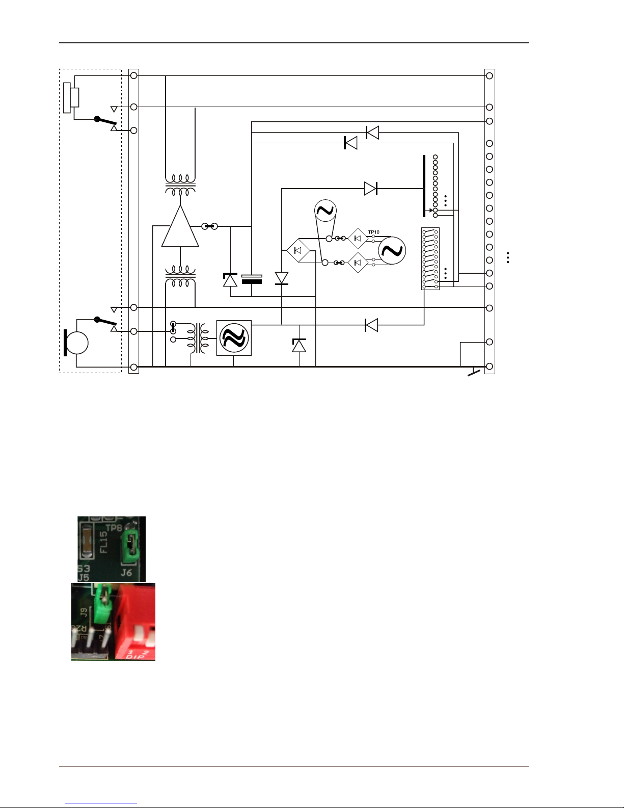
Figure 2: Main station VSP-211-L principle diagram
2.1 Power
● An AC voltage appears between TP10/TP11 and TP12/TP13 when
the hand crank is activated. This voltage is rectied in D19 and D21,
providing DC power for two purposes:
- Powering the amplier
- Creating a call signal
L P8 and P9 together with D17 enables the use of the board with the old inductor.
● When a call is being made, the actual line will carry a generated
voltage. This voltage is fed through the active line via the
corresponding diode D11 and D12 to the amplier.
● A permanent amplier 24 VDC power can be supplied on the
connection block terminal 23 (+) and 24 (-).
L To avoid noise problems, the 24 VDC power supply must be connected via a DC/
DC converter.
L Note that the circuit boards can be used as spare parts for the older VSP units.
When using boards with inductors, remove jumpers from pins J6 and J7/J8 and
insert a jumper on pin J9 located to the left of the DIP switches.
2.2 Calling
● The station’s extension number is set by DIP switches P11 - P22.
This will activate the call signal generator in the called station and
provide power to the amplier.
● The desired station is selected by a 12-way rotary switch.
When turning the hand crank, a voltage is supplied to the selected
line.
 Loading...