

Vingtor IP DECT 6000, 2211000100, 2211000600, 2211050110, 2211100501 Deployment Manual
...
IP DECT Deployment on Ships
A100K10676DEPLOYMENT GUIDE
IP DECT 6000 System

Zenitel Norway AS and its subsidiaries assume no responsibilities for any errors that may appear in this
publication, or for damages arising from the information in it. No information in this publication should be
regarded as a warranty made by Zenitel Norway AS.
The information in this publication may be revised or changed without notice. Product names mentioned in
this publication may be trademarks of others and are used only for identication.
Zenitel Norway AS © 2009

3
IP DECT Deployment on Ships
A100K10676
Contents
1 About this Document .....................................................................................................4
1.1 Before You Begin ......................................................................................................4
1.2 Revision Information .................................................................................................4
1.3 Related Documentation ............................................................................................4
2 IP DECT 6000 System .....................................................................................................5
3 Server 6000 Multi-Cell System .......................................................................................6
3.3.1 Synchronization over Air .................................................................................. 6
3.3.2 Examples of Synchronization Chains ..............................................................6
3.3.2.1 Sync Chain With One Sync Master (Primary Sync Ways) ..................................... 6
3.3.2.2 Synchronization Chain With Secondary Sync Ways .............................................. 7
4 General Layout of a Ship ...............................................................................................9
4.1 Accommodations and Bridge ................................................................................... 9
4.2 Below Main Deck .....................................................................................................9
4.3 Outdoor Areas ...........................................................................................................9
4.4 Base Stations ............................................................................................................9
4.4.1 Recommended placement of base stations .....................................................9
4.5 Leaky Cable Solution .............................................................................................. 10
4.6 Repeaters ...............................................................................................................10
5 Deployment Example of Onboard DECT System ......................................................11
5.1 DECT Deployment based on GA Plan ................................................................... 11
5.2 Base Station / PoE Point Notation .......................................................................... 11
5.3 Bridge Deck ............................................................................................................13
5.4 Third Deck ...............................................................................................................13
5.5 Second Deck ...........................................................................................................14
5.6 First Deck ................................................................................................................14
5.7 Main Deck ............................................................................................................... 15
5.8 Tween Deck ............................................................................................................ 15
5.9 Tank Top Deck ........................................................................................................ 16
6 Deployment Guideline for Accommodations & Bridge ............................................17
7 Deployment Guideline for Below Main Deck .............................................................19
7.1 Engine Room Deployment - Tween Deck ...............................................................19
7.2 Pump and Storage Rooms Deployment .................................................................19
8 Deployment Guideline for Outdoor Areas ................................................................21
8.1 Hangar Deployment ................................................................................................ 21
8.2 Main Deck Deployment ........................................................................................21
Figures
Figure 1 IP DECT 6000 System Conguration .......................................................................................................... 5
Figure 2 Synchronization Chain ................................................................................................................................. 6
Figure 3 Synchronization Chain Layout without Secondary Sync Ways .................................................................... 7
Figure 4 Synchronization Chain with Secondary Sync Ways .................................................................................... 7
Figure 5 Synchronization Chain with Secondary Sync Ways .................................................................................... 8
Figure 6 Sync Chain showing Primary & Secondary Sync Ways .............................................................................. 8
Figure 7 Overview of Primary and Secondary Sync Ways for all Decks .................................................................. 12
Figure 8 Base station deployment examples on First, Second, Third Decks, and Bridge Deck .............................. 18
Figure 9 Base station and leaky cables in Engine Room & Front Azimuth areas on Tween Deck. ......................... 19
Figure 10 Base station & leaky cables in pump room and around moon pool on Tank Top Deck ............................. 20
Figure 11 Base stations & leaky cables in storage rooms and corridor to aft engine rooms on Tween Deck ............ 20
Figure 12 Sync Master base station in Hangar on Main Deck .................................................................................. 21
Figure 13 Base station deployment on Aft Main Deck .............................................................................................. 22
Figure 14 Base station deployment on Main Deck .................................................................................................... 22
4
A100K10676
IP DECT Deployment on Ships
About this Document1
This document contains guidelines for deploying the IP DECT 6000
System on ships, and is intended for qualied technicians who will install,
congure and maintain the system onboard.
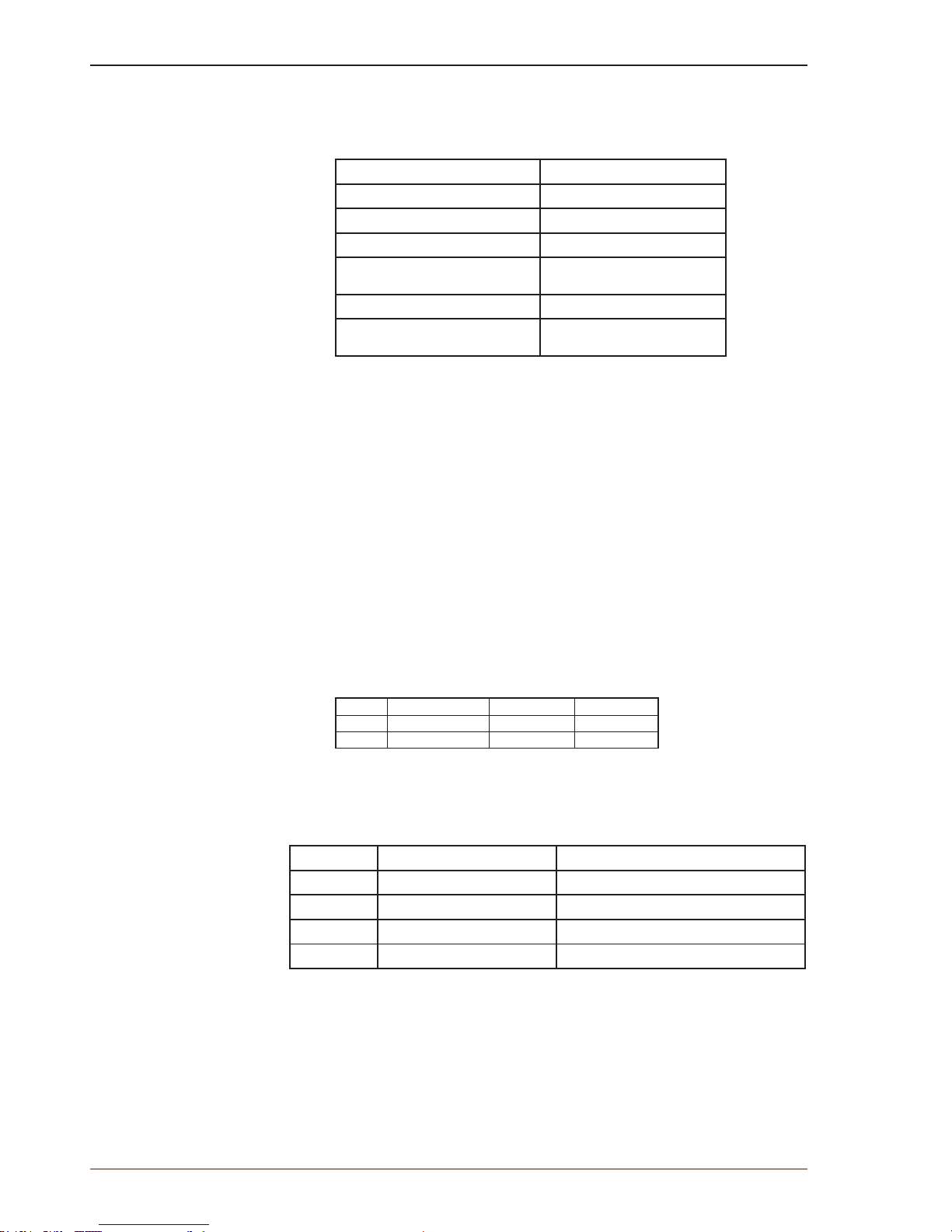
The IP DECT 6000 System comprises the following:
Product Part Number
IP DECT Server 6000 2211000100
IP DECT Base Station 2211000600
Repeater Wall / Repeater Ceiling 2211050100 / 2211050110
DECT Handsets 2211100501, 2211100502,
2211100503, 2211100504
IP DECT Alarm Server 2210020000
IP DECT Base Station with 100m
Leaky Cable and Mounting Kit
2211000605
The installation and conguration of the Server 6000 and the Alarm Server are )
described in the corresponding manuals as listed under Related Documentation
below.
Before You Begin1.1
This document assumes the following:
You have a working knowledge of AlphaCom/ACM exchange ●
operations and that the exchange is installed and initialized and is
working properly.
You have a working knowledge of deployment in general. ●
A site survey has been conducted and the installer has access ●
to these plans. The site survey should determine the number of
handsets and RF channels that are needed.
Revision Information1.2
Rev. Date Author Status
1.0 28-10-2009 HKL Published
1.5 25-1-2011 HKL handsets
Related Documentation1.3
For further information about the IP DECT Server 6000 not covered by
this manual, refer to the following documentation:
Doc. no. Subject Documentation
A100K10652 IP DECT 6000 System IP DECT Installation & Conguration Guide
A100K10677 IP DECT Alarm Server IP DECT Alarm Server Conguration Guide
A100K10777 IP DECT 6000 Conguration IP DECT Quick Conguration Guide
DECT Handset Operation Handset User Guides
5
IP DECT Deployment on Ships
A100K10676
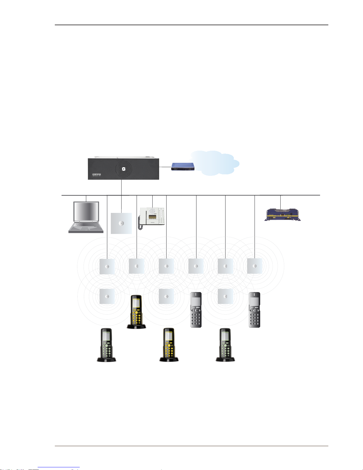
IP DECT 6000 System2
The main components of the IP DECT 6000 System on ships are:
IP DECT Server 6000 ●
Base Station ●
Leaky antenna cable ●
Repeater ●
Handset ●
Alarm Server ●
Administrative Computer ●
IP DECT 6000 System CongurationFigure 1
Base Stati on
Repeater
DECT H andset Rough
DECT Han dset Office
DECT Hands et Rough
DECT Han dset Rough Bluetooth
DECT Hands et Office
DECT Han dset Rough B luetooth
Repeater
Repeater
Base Station
Base S tation Base Sta tion Base Station
Base Station
AlphaCom/ACM Exchange
LAN
PBX / PSTN
SIP Gateway
IP DECT
Server 6000
Administrative
Computer
Intercom
Station
Alarm Server
6
A100K10676
IP DECT Deployment on Ships
Server 6000 Multi-Cell System3
Synchronization over Air3.3.1
Base stations must be placed in such a way that overlap of radio
coverage between the base stations is established.
As a user moves from one base station radio coverage area to
another, the call must be handed over to the next base station. To
create handover between base stations, it is necessary to establish
synchronization chains. If synchronization between base stations is lost,
then handover is not possible and ongoing calls will be terminated.
Each base station must be placed within the radio coverage area of at least one )
other base station.
Examples of Synchronization Chains3.3.2
Certain rules must be taken into consideration when establishing
synchronization chains:
The distance over which synchronization can take place is limited ●
to a distance similar to a loss not exceeding 25 dB. If signal loss
exceeds 25 dB, it is not certain that synchronization will be stable.
For example, the signal measured next to the base station is 100 dB. The handset with test display active is moved away from the
base station until the reading in the display shows 75 dB. This is
the spot where the next base station should be installed.
It is recommended that a base station synchronizes with at least two ●
other base stations, and that a secondary sync way is dened to
ensure system redundancy. If the primary sync way is not working,
then the secondary sync way takes over and the synchronization
chain is not broken.
Synchronization chains for the Server 6000 Solution can be made ●
with base stations.
As the Server 6000 uses the DECT interface to synchronize on, one
base station is congured as the Sync Master. It is recommended to
place the Sync Master on the deck that is mid-way between the decks of
the vessel.
It is recommended to make a site plan. Every base station must be
numbered with Radio ID, Primary sync Radio ID, and Secondary sync
Radio ID.
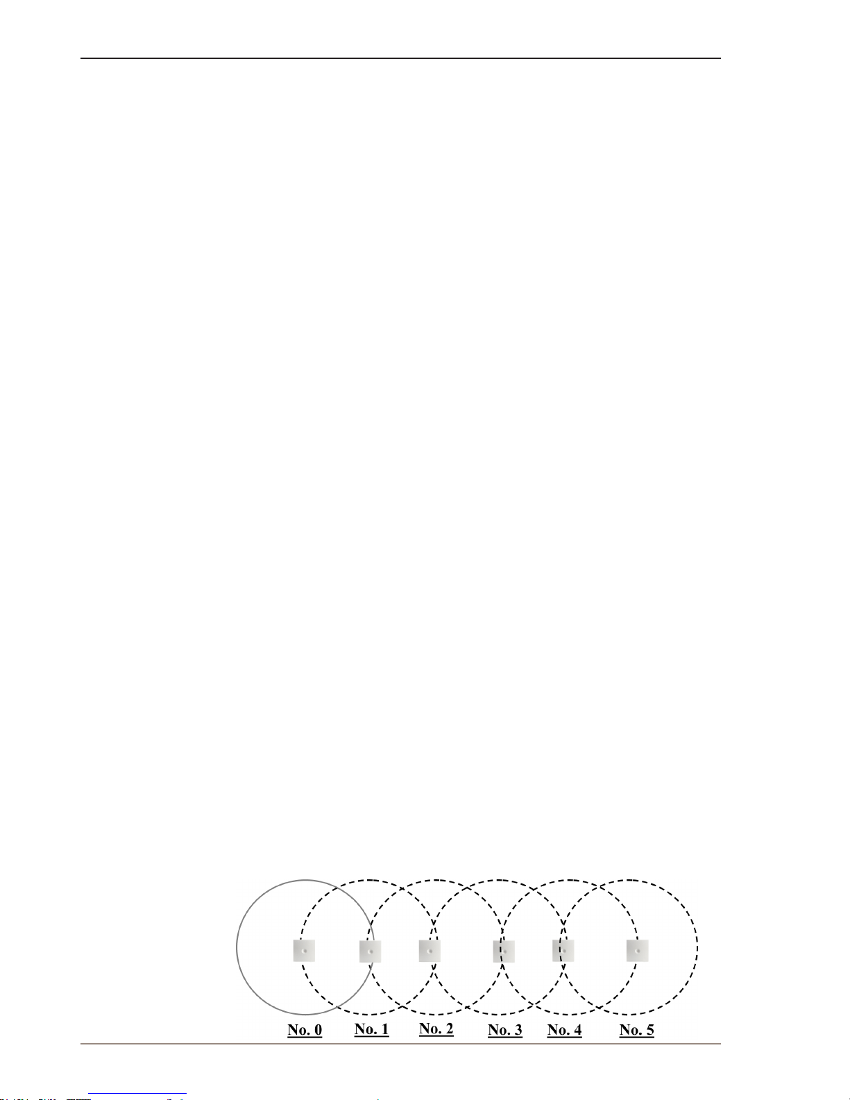
Sync Chain With One Sync Master (Primary Sync 3.3.2.1
Ways)
Figure 2 Synchronization Chain
7
IP DECT Deployment on Ships
A100K10676
The synchronization chain must always overlap with the base station to sync on.
No. 0 is the Sync Master (can be numbered 0 to 255). Other base stations are connected to the Sync Master through the synchronization chain.
If one of the base stations in the synchronization chain is not working, then all base stations behind are also not working.
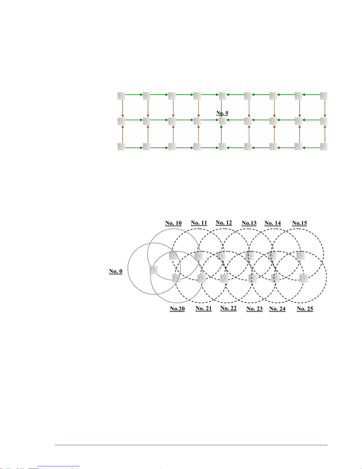
Figure 3 Synchronization Chain Layout without Secondary Sync Ways
No. 0 ● is the Sync Master (can be numbered 0 to 255).
Green line ● : Shows the primary sync ways.
Brown line ● : Only handover overlap is needed.
Synchronization Chain With Secondary Sync Ways3.3.2.2
Figure 4 Synchronization Chain with Secondary Sync Ways
No. 0 is the Sync Master (may be numbered 0 to 255). No. 10 and No. 20: Primary and secondary sync on No. 0. No. 11: Primary sync on No. 10 and secondary sync on No. 21. -
8
A100K10676
IP DECT Deployment on Ships
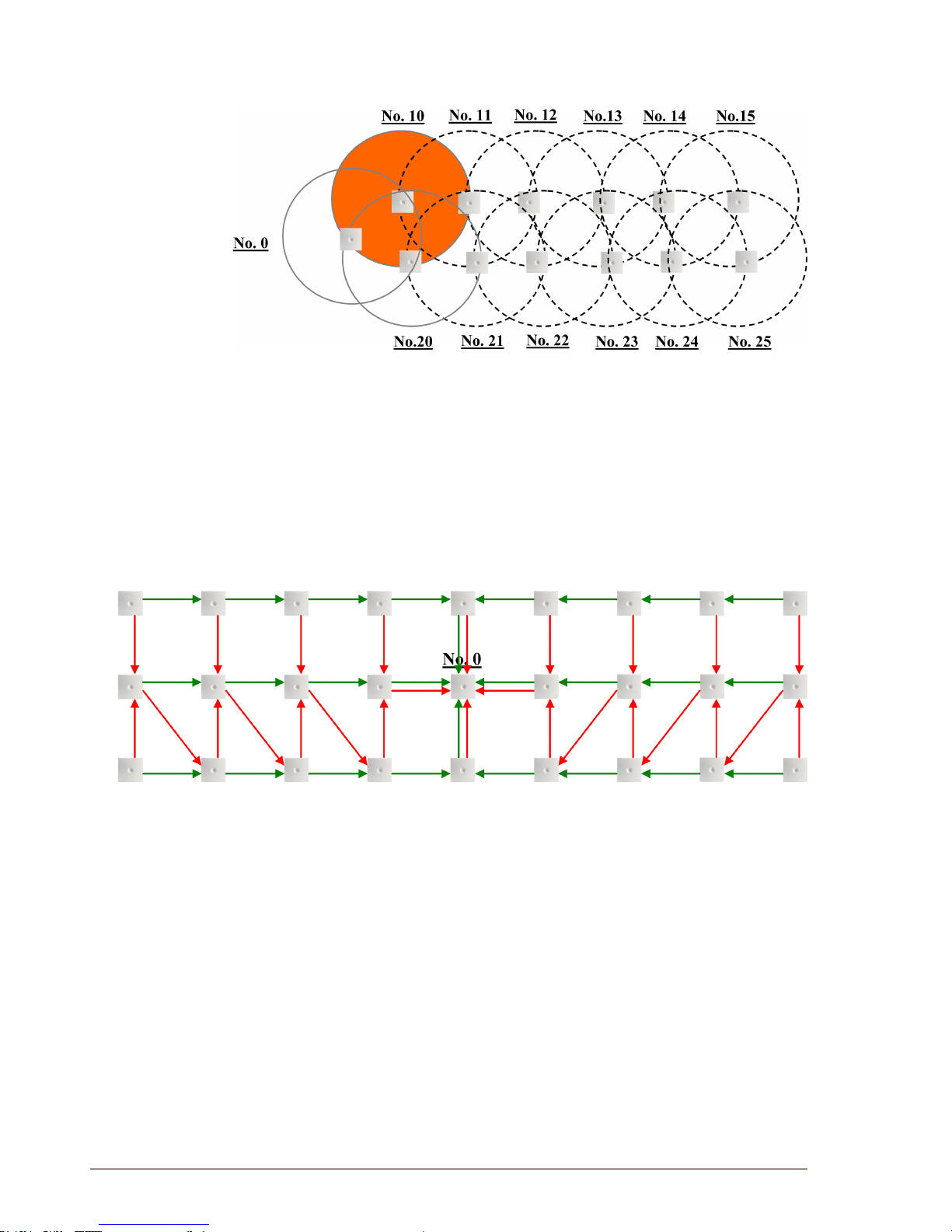
Synchronization Chain with Secondary Sync WaysFigure 5
No. 0 is the Sync Master (may be numbered 0 to 255). No. 10 and No. 20: Primary and secondary sync on No. 0. No. 11: Primary sync on No. 10 and secondary sync on No. 21. -
In the example above, base station No. 10 is down. Consequently, base
station No. 11 must use the secondary sync way on base station No. 21.
Figure 6 Sync Chain showing Primary & Secondary Sync Ways
No. 0 ● is the Sync Master (may be numbered 0 to 255).
Green line ● : Shows the primary sync ways.
Red line ● : Shows the secondary sync ways.
For more information, please refer to the IP DECT 6000 System Installation &
Conguration Guide.
 Loading...