

INSTALLATION & USER MANUAL
CTB-100V
Command Talk Back & Public Address System
A100K10864

Installation & User Manual System CTB-100V
i
Table of Contents
1. GENERAL...................................................................................................................................................................... 1
1.1 Purpose of this manual ........................................................................................................................................................1
1.2. Related documents ...............................................................................................................................................................1
1.3. Publication log ......................................................................................................................................................................1
1.4. Requirements........................................................................................................................................................................1
1. SYSTEM OVERVIEW.................................................................................................................................................... 2
2.1. Introduction........................................................................................................................................................2
2.2. Features .................................................................................................................................................................................2
2.2. Optional Equipment.............................................................................................................................................................3
2.4. Functions & User Facilities. ................................................................................................................................................4
2.4.1 General..................................................................................................................................................................................4
2.4.2 Line selection / Single call....................................................................................................................................................4
2.4.3 Signal and extra signal device for substations...................................................................................................................4
2.4.4 Group call..............................................................................................................................................................................4
2.4.5 All call....................................................................................................................................................................................5
2.4.6 Calls from and between Operation panels.........................................................................................................................5
2.4.7 Call from substations ...........................................................................................................................................................5
2.4.8 Parallel communication.......................................................................................................................................................6
2.4.9 AUX function........................................................................................................................................................................6
2.4.10 Audio from external audio to All........................................................................................................................................6
2.4.11 Operation of external Public address system. ...................................................................................................................7
2.4.12 Emergency Public address operation.................................................................................................................................7
2.4.13 Hands free operation............................................................................................................................................................8
2.4.14 Privacy functions ubstation STB-1.....................................................................................................................................8
2.4.15 Two-way voice communication, Nautical Safety...............................................................................................................8
2.4.16 Monitor loudspeaker............................................................................................................................................................9
2.4.17 External loudspeaker...........................................................................................................................................................9
2.4.18 Dimmer of call light..............................................................................................................................................................9
2.4.19 Volume adjustment ..............................................................................................................................................................9
2.4.20 Powersupply SPS-4 (Option)...............................................................................................................................................9
3. INSTALLATION AND CONFIGURATION PROCEDURES......................................................................................... 10
3.1 General ................................................................................................................................................................................10
3.2 Mounting & Terminal configuration. ..............................................................................................................................10
3.2.1 Central unit CU-100 & CU-200........................................................................................................................................10
3.2.2 Operation panel CTB-10 & 20 ..........................................................................................................................................12
3.2.3 CTB-10W / V01, CTB-20W / V01.....................................................................................................................................12
3.2.4 Identification sign plate CTB-panels................................................................................................................................12
3.2.5 Substations and other equipment. ....................................................................................................................................12
3.2.6 Identification sign plate substation...................................................................................................................................12
3.3 Cable requirements............................................................................................................................................................12
3.4 Power supply requirements...............................................................................................................................................13
3.5 Set priority in CU-100 & CU-200.....................................................................................................................................13
3.6 Set receive-call from substation. .......................................................................................................................................13
3.7 Set public address zones SPA............................................................................................................................................13
3.8 Volume and signal adjustment..........................................................................................................................................14
3.8.1 Substations ..........................................................................................................................................................................14
3.8.2 Auxiliary and Public address............................................................................................................................................14
3.8.3 Call signal............................................................................................................................................................................14
3.9 Dimmer on / off in Operation panel .................................................................................................................................15
3.10 Substation STB-1................................................................................................................................................................15
3.11 Substation STB-3................................................................................................................................................................15
3.12 Substation STB-5................................................................................................................................................................15
3.13 Installation for C500 Nautical Safety...............................................................................................................................15
4. USER INSTRUCTIONS...............................................................................................................................................16
4.1 Operation from the operation panel.................................................................................................................................16
4.1.1 Make a call to an substation..............................................................................................................................................18
4.1.2 Make a call to group of substations..................................................................................................................................19
4.1.3 All Call.................................................................................................................................................................................20
4.1.4 Handsfree operation...........................................................................................................................................................21
4.1.5 Give signal to substations with extra signal device.........................................................................................................21
4.1.6 Receive a call from an substation.....................................................................................................................................22
4.1.7 Receive a call from two or more substations...................................................................................................................23
4.1.8 AUX function......................................................................................................................................................................24
4.1.9 Audio from external audio to All......................................................................................................................................25
4.1.10 Public Address Operation of external system .................................................................................................................26
4.1.11 Emergency Public Address Operation.............................................................................................................................27
4.1.12 Volume .................................................................................................................................................................................29
4.1.13 Dimming of call light..........................................................................................................................................................29
4.2 Parallel communication.....................................................................................................................................................30
4.2.1 Operation.............................................................................................................................................................................31
4.3 Operation from substations...............................................................................................................................................32

1. GENERAL
1.1 Purpose of this manual
This manual supplies an engineer with the information required to install and commissioning
a CTB-100V system and the end-user with all necessary instructions for operating the CTB_100V system.
Refer to Service Manual for maintenance and repair.
The manual can also be used as a guideline for design and planning of the sy stem.
1.2. Related documents
The following related documents are available:
Single line and connections drawing in Autocad format.
Declaration of conformity doc.no.DC CTB 20040601 SH
1.3. Publication log
Product / Ver.no.: CTB Ver.07
Title: CTB-100V Installation & User Manual
Doc.no. / Rev. CTB-100V_iu
Author: S.E.Nilsen
Verified By:
Revision Issued Changes / Comments
00 2001.09.06 First issue, User & Technical Manual
Draft I 2005.10.06 Second release, name changed to Installation & user
manual, CTB Ver.07 for approval
01 2006.06.08 Third release to meet requirement from Det Norske Veritas
(DNV)
01.1 2007.01.22 Replaced drawing CTB_cc3 Rev.04 with Rev.05
And dwg.CTB-100_cc2 Rev.04 with Rev.05
A100K10864 2008.08.26 New front and back p ag e. Doc.no. CTB-100_iu Rev. 01.1
is replaced by this document no.
Zenitel Norway AS and its subsidiaries assume no responsibilities for any errors that may appear in this
publication, or for damages arising from the information in it. No information in this publication should be
regarded as a warranty made by Zenitel Norway AS.
The information in this publication may be updated or changed without notice. Product names mentioned in
this publication may be trademarks, they are used only for identification.
Zenitel Norway AS, August 2010
1.4. Requirements
The CTB system and its components have been tested according to following regulations:
• IEC 60533: Second edition, 1999; «Electrical and electronic installation in ships – Electromagnetic
compatibility».
• IEC 60945: Fourth edition, 2002; «Maritime navigation and radio communication equipment and
systems - General requirements - Methods of testing and required test results».
• IACS E10: Corr. 1 July 2003; «Unified environmental test specification – Testing procedure for electric
control and monitoring , safety and protect i o n, o n bo ard computer based systems and peripherals,
loading instruments, internal communication and other electrical equipment as considered appropriate».

Installation & User Manual System CTB-100V
ii
4.3.1 Operation from STB-1.......................................................................................................................................................35
4.3.2 Operation from STB-2.......................................................................................................................................................35
4.3.3 Operation from STB-3.......................................................................................................................................................36
4.3.4 Operation from STB-5.......................................................................................................................................................37
4.3.5 Operation from STB-5GN.................................................................................................................................................38
4.3.6 Operation from HE-112M / HE-112MT..........................................................................................................................38
4.3.7 Operation from VH-10M / VH-10M-T............................................................................................................................39
4.3.8 Operation from VHM-10 / VHM-10-T............................................................................................................................39
4.3.9 Operation from NEBB-42EX / EX Loudspeaker............................................................................................................40
5. COMMISSIONING.......................................................................................................................................................41
5.1 General ................................................................................................................................................................................41
5.2 Mechanical Inspection .......................................................................................................................................................41
5.3 Cable Inspection .................................................................................................................................................................41
5.4 Check Configurations. .......................................................................................................................................................41
5.5 C500 Nautical Safety..........................................................................................................................................................41
5.6 Starting up the system........................................................................................................................................................42
5.8 Trouble shooting.................................................................................................................................................................43
6. INSTALLATION DRAWINGS AND DATASHEET ....................................................................................................... 46
6.1 Installation drawings..........................................................................................................................................................46
6.2 Datasheets............................................................................................................................................................................46

Installation & User Manual System CTB-100V
2
1. SYSTEM OVERVIEW
2.1. Introduction
The Command Talk Back System CTB-100V is specially designed for important communication for use in rough
marine environment. Available in 10 and 20 line version.
The CTB system consist of a central unit CU-100 or CU-200 with up to 4 operation panels
for use on bridge console, bridge wings, engine control room etc. and a comprehensive range of substations and
field equipment for use indoor, outdoor and noisy areas.
The system includes many facilities and can operate together with PA-system to increase functionality and fields
of operation.
2.2. Features
• 10 or 20 line selection • 100V line power amplifier.
• 4 Operation panels • Dimmable panel background light
• Gooseneck or handheld microphone. • Step volume control
• Parallel Communication. • Output for extra signal device for all substation lines
• All call / Group Call facility • Output for external loudspeaker
• Public Address Operation • Input for external microphone.
• AUX / Alarm input • Dimension panels H:144 x W: 240 x 100
• Hands free operation. • Power 22 - 32 V DC
• Cover requirement for DNV C500 Nautical Safety
Operation panel CTB-20W/V01
Foot-switch
Signal unit
1
EEx de IIC T6 PTB Nr.Ex-87.B.1009
Ui 690V
CEAG
GHG 411
I16A
Substation STB-3
Line 19
100V Ex-loudspeaker Ex-push button box
Substation STB-5
Line 17
HAS-1
ETC-STB5
Signal unit Signal unit
Substation STB-5GN
Line 18
Signal unit
Signal unit
VML-15T
VML-1520
P-MT7
P-66
Substation line 20
P-66
P-66
Signal unit
Signal unit
Central unit CU-200
MB-30G
ETC-1-TB
MB-30G
TC-1-TB
Signal unit
Sub-station STB-1
Line 5
Sub-station STB-1
Line 6
Sub-station STB-1
Line 7
Substation STB-2
Line 11
VML-15T
Substation STB-2
Line 10
`
VML-15
Substation HE-112MT
Line 9
Substation HE-112MT
Line 8
Operation panel CTB-20
Operation panel CTB-20W/V0
1
Line 2
Line 3
Line 1
Operation panel CTB-20
Line 4
10m cable
Substation VHM-10MT
Line 12
Substation VH-10MT
Line 13
CD-2
VML-15T
HP-8
HP-8
100V Loudspeaker line
Line 14
100V Loudspeaker line
Line 15
100V Loudspeaker line
Line 16
ON
OFF
VPA-120
POWER AMPLIFIER
100V POWER AMPLIFIER
DC ok
24V DC OUT
24V DC EMERGENCY
230/115V AC MAIN
POWER SUPPLY

Installation & User Manual System CTB-100V
3
2.2. Optional Equipment
See chapter 6 for further details and datasheet
Central units, operator panels and microphones.
CU-100 Central unit 10 line 24V DC
CU-200 Central unit 20 line 24V DC
CTB-10 Operation panel, 10 lines
CTB-20 Operation panel, 20 lines
CTB-10W / V01 Operation panel, 10 lines, weatherproof. Bulkhead mounting only.
Including external loudspeaker HP-8.
CTB-20W / V01 Operation panel, 20 lines, weatherproof. Bulkhead mounting only.
Including external loudspeaker HP-8.
HP-8 Horn loudspeaker, part of CTB-10W V01 and CTB-20W V01
VMT-603 All Call statio n WT, for wall mounting
MB-30G
Gooseneck Microphone with plug for CTB-10 & 20
ETC-1-TB Hand microphone with curled cord and plug for CTB-10 & 20
P-66 Hand microphone with curled cord and plug, WP
P-66/10 Hand microphone with 10mtr. Cable and plug, WP
AW8121 Power amplifier 120W / 100V 220V AC/24V DC
AW8241 Power amplifier 240W / 100V 220V AC/24V DC
P-8501 Power amplifier 500W / 100V 220V AC/24V DC
RS-3D Cabinet for power amplifier
Substations and other equipment
STB-1 Substation indoor wall mounted with call and answer button.
STB-2 Call box WP wall mounted for use together with VML-1520.
STB-3 WP Combined call-plug box w/relay unit wall mount for headset, loudspeaker and
extra signal device,
PMT-7 Portable headset w/10mtr. Cable and plug for STB-3
VML-1520 Horn loudspeaker 15W 20ohm IP-65
STB-5 Flush mounted substation w/relay, for mic. or handset
STB-5GN Flush mounted substation w/relay, and gooseneck microphone
HAS-1 Handset for STB-5
ETC-STB5 Hand microphone with curled cord and plug for STB-5.
VH-10M Portable deck loudspeaker with callbox and 10M cable and plug.
VH-10M-T Portable deck loudspeaker 100V w/ callbox and 10M cable and plug
CD-2 Plugbox for VH-10M
VHM-10 Special deck unit with hand microphone mounted in cabinet.
VH-10M-T Portable deck loudspeaker 100V w/ callbox and 10M cable and plug
HE-112M Outdoor loudspeaker with call button WP IP-66
HE-112M-T Outdoor loudspeaker 100V with call button WP IP-66
NEBB-42EX Call box, Ex-approved
VML-15T Horn loudspeaker 15W 100V IP-65
Bridgewing equipment, microphones
STB-6 Flush mounted substation for handmic.
STB-6GN Flush mounted substation w/gooseneck mic.
SB-4 WP Plug box for portable microphone, headset and loudspeaker, wall mounted.
P-66 Hand microphone with curled cord and plug, WP
P-66/10 Hand microphone with 10mtr. Cable and plug, WP
Additional equipment
WBOKS Wall mounted box for CTB-10/20
STBOKS5 Wall mounted box for STB-5 and STB-5GN
STBOKS Wall mounted box for STB-6 ad STB-6GN
VML-1520 Horn loudspeaker 15W 20ohm IP-66
SPS-4 Power supply 115/230V AC 24V DC w/ automatic switchover relay.
BLK5-24 Flash beacon 24V AC/DC 5 Joule IP65
EHS-24 Rotary light 24V DC IP54
A-100 Electronic alarm horn 24V DC – IP55 – 100dB
Installation & User Manual System CTB-100V
4
2.4. Functions & User Facilities.
2.4.1 General
The CTB-100 system consist of 1 central unit CU-100 or Cu-200, 1 to 4 operation panels, 1 to 20 substations or
loudspeakers and one 100V power amplifier. On system with more than 1 operation panel, each panel take one
substation line. The system have one speech channel and operation from one operation panel will be indicated in
other operation panels. The operation panels follows a priority hierarchy 1 to 4, that means operation panels with
higher priority can override operation panels with lower priority.
Operation panel CTB-10 & CTB-10W_V01 with 10 line selection, CTB-20 & CTB-20W_V01 with 20 line
selection. CTB-20 used in the presentation.
|
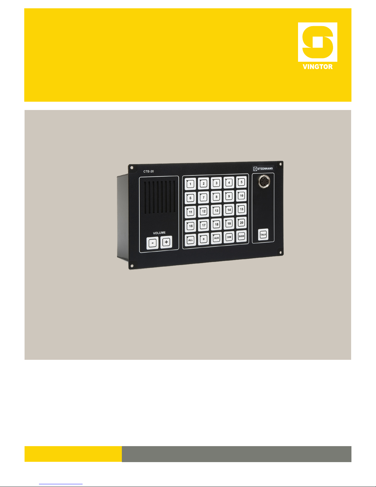
2.4.2 Line selection / Single call
1 - 10 (20) substations or other operation panels can be selected from
any operation panel by pressing respective line button. Indicated with
steady green light in LED. (Light emitting diode)
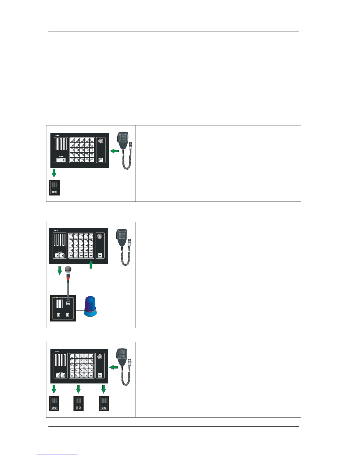
2.4.3 Signal and extra signal device for substations.
A call signal can be given to selected station. The function will also
activate an 24VDC max 50mA to substation with relay or direct
connected external signal device
2.4.4 Group call
Group of substations or other operati o n panels can be selected by
pressing respective number of line buttons. Indicated with steady green
LED.
Installation & User Manual System CTB-100V
5
2.4.5 All call
20
11
4
10
3
2
All call message can be distributed from any operation panel to all
substations and other operation panels.
All call message will also activate Public Address System if connected.
Indicated with steady green LED in the «ALL» push button.
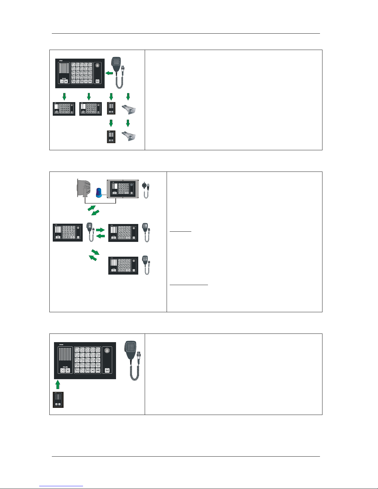
2.4.6 Calls from and between Operation panels.
Up to 4 operation panels can be connected.
Calls can be made from any operation panel to substations.
And calls can be made from any operation panel to another by
pressing respective line button.
In this stage the called operation panel act as a substation.
Calls from one operation panel will be indicated in all operation
panels.
Priority:
One operation panel is always decided to be a master station
with highest priority.
The priority follows a hierarchy 1 to 4,
with operation panel 1 as highest priority .
It is a standard setting. With dip-switches in the central unit the
priority can be changed. (See chapter 3.5)
Type of panels:
CTB-10 Operation panel 10 line selection, indoo r use.
CTB-10W/V01 Operation panel 10 line selection, WP.
CTB-20 Operation panel 20 line selection, indoo r use.
CTB-20W/V01 Operation panel 20 line selection, WP.
2.4.7 Call from substations
Calls from a substation can be received in all operation panels.
Indicated with flashing green light in LED in respective line.
Preferred operation panels can be set to receive a call with an acoustic
signal in addition.
Installation & User Manual System CTB-100V
6
2.4.8 Parallel communication
P
T
T
S
W
I
T
C
H
P
T
T
S
W
I
T
C
H
Function with operation from parallel microphone / loudspeaker
located on bridge wings, or other locations where parallel
microphone / loudspeaker needed.
Note! Line selection have to be set up from the operation panel.
2.4.9 AUX function
AUX
External entertainment, message or alarm can be distributed trough the
CTB system by using push button switch “AUX” together with line
selection switches.
0dB signal from the external system connected to the CTB system will
be addressed to selected substations.
The TALK button on operation panels or PTT butt o n on ha nd
microphone will override the AUX to giving a all call message.
External system can be:
• VHF radio System
• Entertainment system.
2.4.10 Audio from external audio to All
20
11
4
10
3
2
Alarm (or any audio) from external system can be distributed trough the
CTB system.
An potentional free contact and 0dB signal from the external system
activate the CTB and the message will be addressed to all substations and
operation panels.
The talk button on the operation panel or PTT button on hand
microphone will override the external audio.
Normal talk back functions can not be used in this mode.
External system can be:
• Alarm system.
• External Public Address System
Note! Only the operator of the external system can switch of the external
audio.
Installation & User Manual System CTB-100V
7
2.4.11 Operation of external Public address system.
I
0
SERIES POWER AMPLIFIER
The four last line push buttons on the operation panels can be set to
access 1 to 4 public address zones of external system.
CTB-10 & CTB-10W_V01: Push button marked 7-8-9- 10
CTB-20 & CTB-20W_V01: Push button marked 17-18-19-20
Note! Other operation panels with higher priority can override the PAmessage.
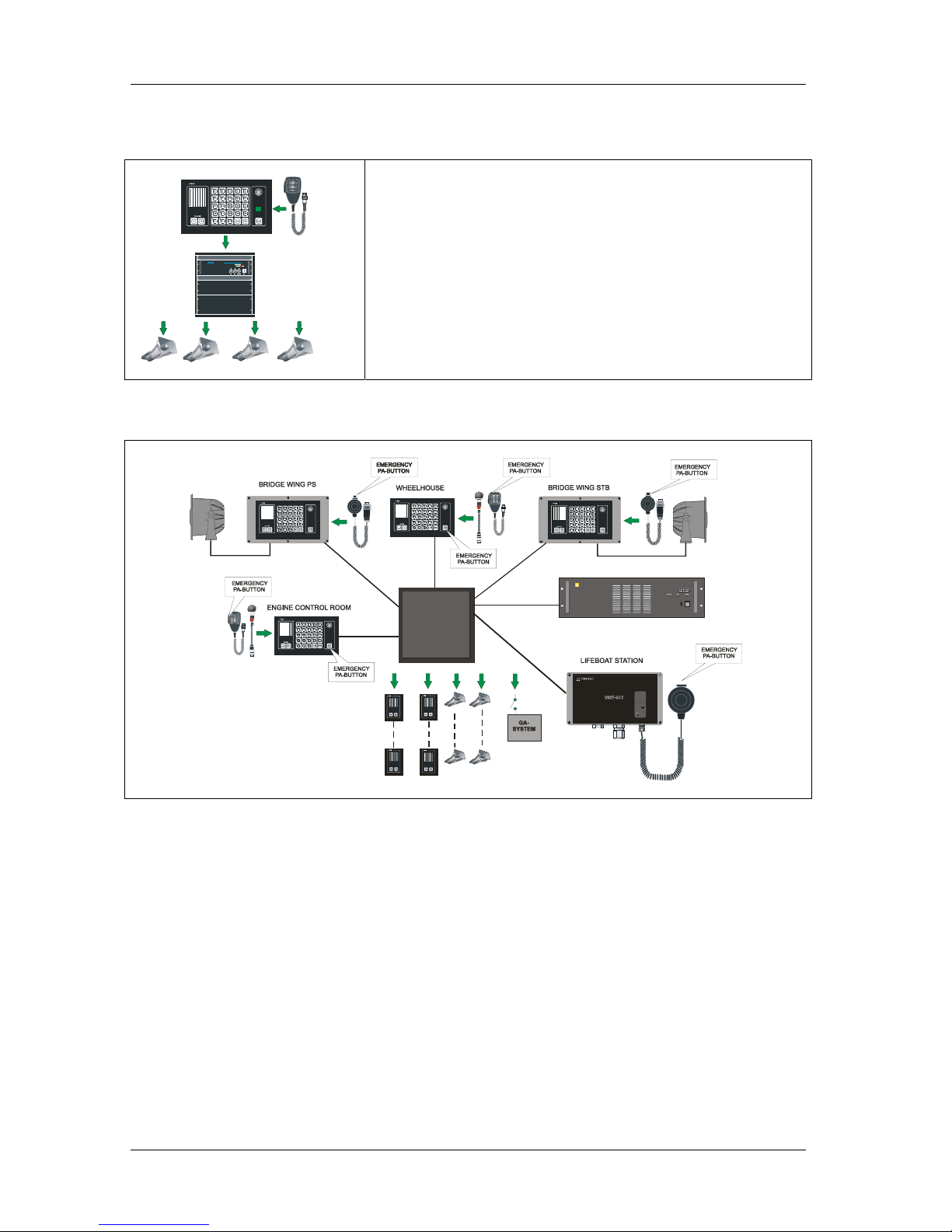
2.4.12 Emergency Public address operation.
Central unit CU-200
ON
OFF
VPA-120
POWER AMPLIFIER
100V POWER AMPLIFIER
In order to comply with PA-requirements, two PA call stations are required: The CTB-100V system are designed
for use with up to four operation panels that can be used as Emergency call stati ons. I n ad di t i on o ne or more All
call station (Ex. Lifeboat stations) can be used as Emergency call stations.
Following functions:
• Mute of the External Alarm System (General / Fire Alarm)
• Operation panel with 1
st
priority, normally bridge, can override other operation panels.
Type of Operation panels/ Emergency call stations:
• CTB-10 Operation panel 10 line selection, in do o r use. Hand or gooseneck microphone.
• CTB-10W/V01 Operation panel 10 li ne selection, WP. Handmicrophone onl y.
• CTB-20 Operation panel 20 line selection, in do o r use. Hand or gooseneck microphone.
• CTB-20W/V01 Operation panel 20 li ne selection, WP. Handmicrophone onl y.
• VMT-603 All call station WT with handmicrophone.
Installation & User Manual System CTB-100V
8
2.4.13 Hands free operation
Foot-switch
Parallel station
STB-6GN
Foot-switch
Foot-switch
Handsfree operation of operation panel or parallel station.
Option 1
Operation panel with gooseneck microphone MB-30G and footswitch
U2410.
Option 2
Parallel station type STB-6GN with gooseneck microphone MB-30G and
footswitch U2410.
2.4.14 Privacy functions ubstation STB-1
Substation STB-1 is designed for indoor use; cabins, mess room etc.,
and prepared with privacy function.
It means ; Listening is not possible in the central unit from STB-1.
After a call is set up from the central unit, the operator of STB-1 have
to use TALK button for communicate with the central unit.
(STB-1 can also be set to normal talk back function, see pos.3.10)
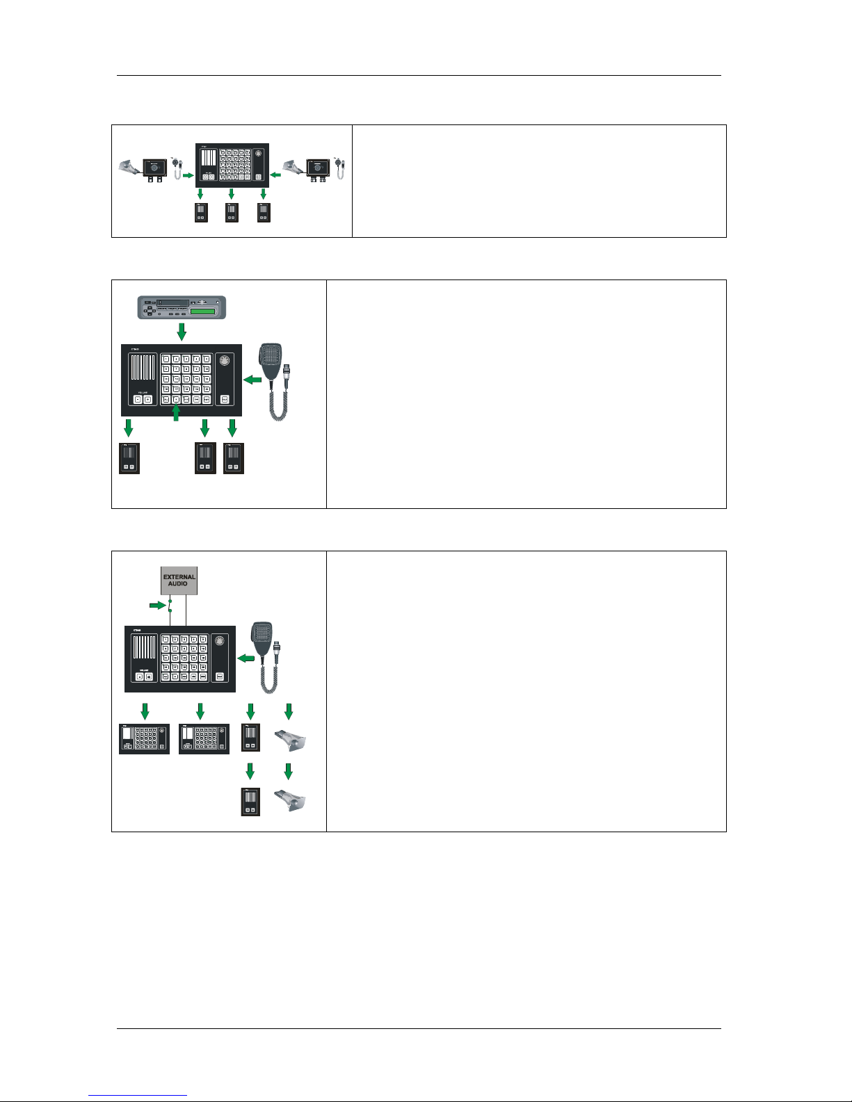
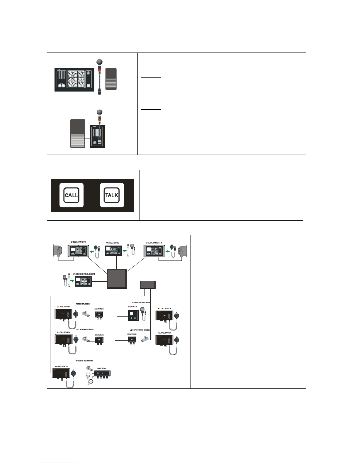
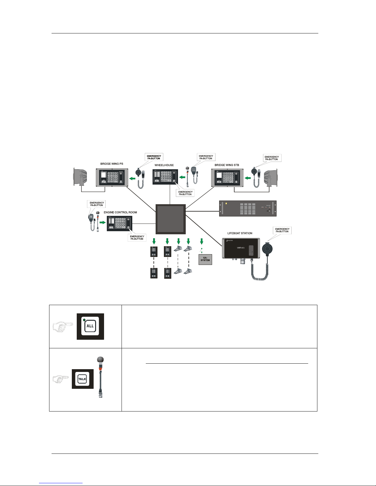
2.4.15 Two-way voice communication, Nautical Safety
1
CENTRAL UNIT CU
JUNCTION BOX
Configuration to meet requirement for hands free
two-way voice communication according to
DNV rules for Nautical Safety.
Following locations has operation panels with all
call:
- Bridge wings
- Wheelhouse
- Engine control room
Following locations has substations and
additional all call stations:
- Forecastle deck (fore mooring station)
- Aft mooring station
- Midship mooring station
- Steering gear room
- Cargo control room
Installation & User Manual System CTB-100V
9
2.4.16 Monitor loudspeaker.
The monitor loudspeaker is located in front of the operation panels
CTB-10 & CTB-20. CTB-10W_V01 & CTB-20W_V01 with external
loudspeaker only.
For distribution of audio; message or alarm signals.
2.4.17 External loudspeaker.
External loudspeaker for improved and higher sound level can be
used. Connected in parallel with the monitor loudspeaker in CTB-10
and CTB-20. Located nearby the operation panel.
Note!
CTB-10W_V01 & CTB-20W_V01 operation panels only equipped
with external loudspeaker.
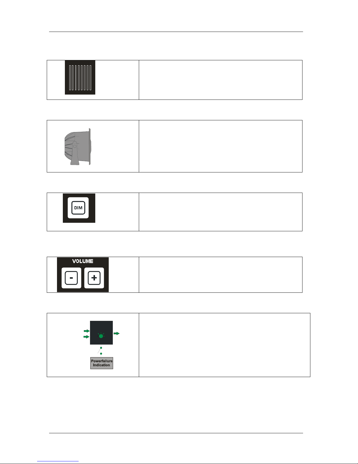
2.4.18 Dimmer of call light.
Intensity of the push button light can be adjusted by pressing DIM
button.
Switch between two steps max.and 1/3. Default is set to max.
Dimmer can be set to on /off by dip-switch.
2.4.19 Volume adjustment
By pressing + or - buttons repeatedly, you can increase or decrease the
listening volume in the central unit
This will also affect the volume for an external speaker connected to
the panel.
2.4.20 Powersupply SPS-4 (Option)
DC ok
24V DC OU
T
24V DC EMERGENCY
230/115V AC MAIN
POWER SUPPLY
The power supply SPS-4 is designed with power failure contact and
automatic switch over relay.
It means indication and automatic switch over to 24V DC emergency
power supply when mains supply or power module fails.
Installation & User Manual System CTB-100V
10
3. INSTALLATION AND CONFIGURATION PROCEDURES
3.1 General
For proper installation and operation of the CTB-system we recommend to read this section
thoroughly together with installation drawings in chapter 6.
Make sure that all mounting and cabling are correct before switching on the system
3.2 Mounting & Terminal configuration.
3.2.1 Central unit CU-100 & CU-200
The central unit is the basis of a system. It should be bulkhead mounted in a normal and ventilated indoor
environment with a temperature of max. 55
0
C. See drawing CU_dd for mounting details.
Note ! Make sure that it is sufficient space for cables and maintenance.
It is equipped with pluggable screw terminals for cables max.2,5mm
2
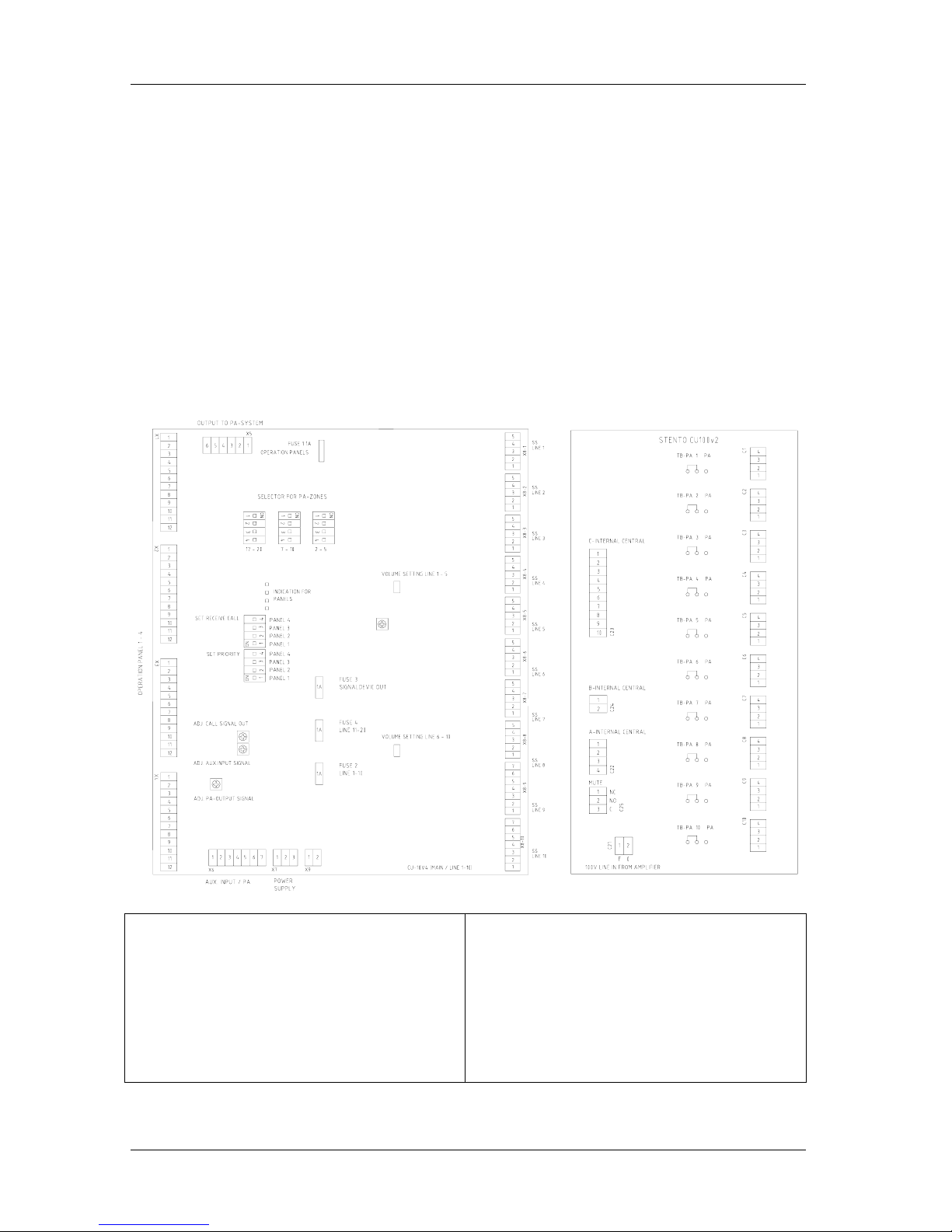
Fig. CU-100 See drawing CU-100_lo for further details.
Terminal block X1-X4 Connection of operation
panels.
Terminal block X5 Output to the PA-system.
Terminal block X6 AUX and PA input.
Terminal block X7 Power supply.
Terminal block X8 1-10 for Connection Substations.
Terminal no.3 – 4 24V DC to extra signal device.
Terminal no.5 is ground point for each substation
screen.
Terminal block C1-C10 for Connection Substations.
Terminal no.1 – 2 substation line low impedance
Terminal no.3 – 4 substation line 100V
Terminal block C25 MUTE for external alarm
system
Other terminal blocks for internal use.

Installation & User Manual System CTB-100V
11
Fig. Additional PCB for CU-200 See drawing CU-200_lo for further details.
Terminal block X8 11-20 for Connection Substations.
Terminal no.3 – 4 24V DC to extra signal device.
Terminal no.5 is ground point for each substation
screen.
Terminal block C1-C20 for Connection Substations.
Terminal no.1 – 2 substation line low impedance
Terminal no.3 – 4 substation line 100V
Terminal block C25 MUTE for external alarm
system
Other terminal blocks for internal use.
Installation & User Manual System CTB-100V
12
3.2.2 Operation panel CTB-10 & 20
The operation panels indoor can be flush or bulkhead mounted in a normal and ventilated indoor environment
with a temperature of 0 - 55
0
C. See drawing CTB-1020_dd1 for mounting details.
Note ! Make sure that it is sufficient space for cables and maintenance.
It is equipped with 2x cable gland PG-16 and plugable screw terminals for cables max.2,5mm
2
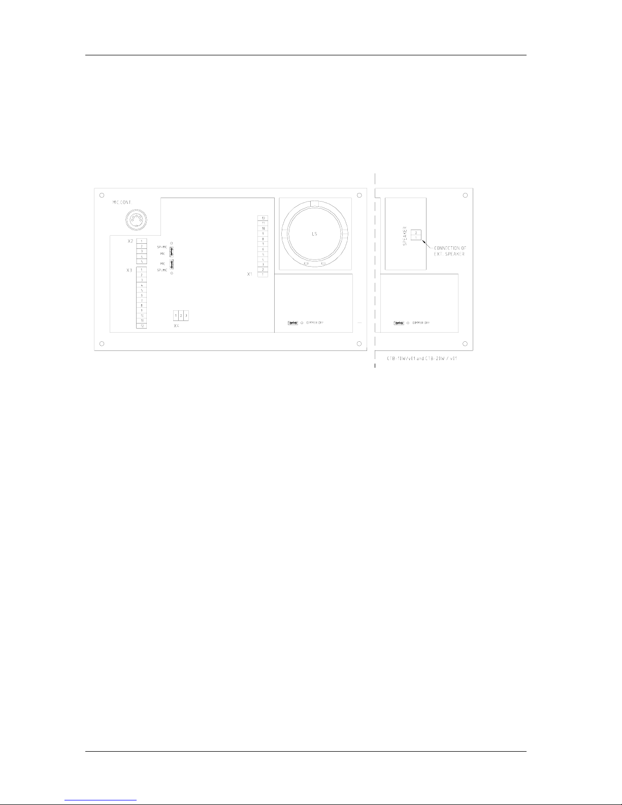
See drawing CTB-1020_lo for terminal and
Terminal block X1: For connection to the central unit.
Terminal block X2: Not in use
Terminal block X3 For connection to external loudspeaker, microphone and parallel microphone.
Terminal block X4 Potentional free contact for extra signal unit.
Terminal block SPEAKER 1-2 for external loudspeaker HP-8 (CTB-10W / V01, CTB-20W / V01)
3.2.3 CTB-10W / V01, CTB-20W / V01
This weather proof operation panels IP-66 is for bulkhead mounting only. Including
external loudspeaker HP-8 Ref. drawing CTB-1020W_dd for mounting details and datasheet for HP-8.
It is equipped with 2x cable gland PG-16 and plugable screw terminals for cables max.2,5mm
2
Ref. drawing CTB-1020_lo for lay out terminals drawing CTB-102 0W_dd for mounting details and datasheet for
HP-8.
Note ! Make sure that it is sufficient space for cables and maintenance.
3.2.4 Identification sign plate CTB-panels
A sign plate with directory / substation number for all substations has to be placed close to the CTB-panels.
3.2.5 Substations and other equipment.
Ref. datasheets for dimension, cut out and mounting.
Note ! Make sure that it is sufficient space for cables and maintenance.
3.2.6 Identification sign plate substation
A sign plate with each substation number has to be placed on or close to each substation.
3.3 Cable requirements
All signal cables have to be approved ship-cable of type twisted pair with outer braided copper screen.
See cable connection drawings in chapter 6 for further details.
The screens must be interconnected in junction boxes and grounded in the central unit only.
Terminal block X8 1-20 terminal no.5 is ground point for each substation screen
Terminal block X1,2,3,4 / no.11 is ground poi nt fo r eac h o perat ion panel.
Power cable has to be approved ship cable min. 3 x 1,5mm
2
Note! The central unit has to be connected to the vessels central ground.
Proper grounding is essential for reliable operation.
Installation & User Manual System CTB-100V
13
3.4 Power supply requirements
24VDC -10% + 33% (21,6 – 32VDC) Current consumption max. 4A
System power supply should be wired and fused independently from other systems.
1. 24V DC from ships 24V DC system.
2. 24V DC from power supply SPS-4 230V AC /.24V DC with automatic switch to 24V DC emergency power
supply.
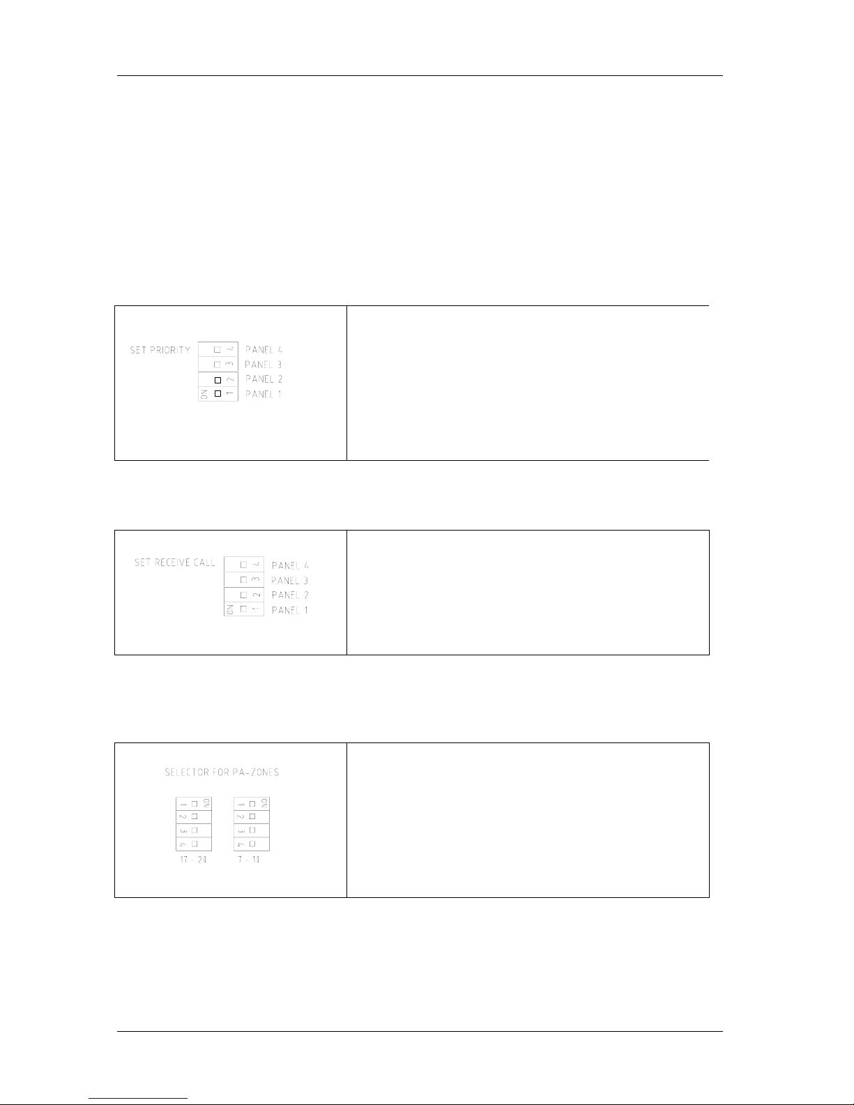
3.5 Set priority in CU-100 & CU-200
Ref. drawing CU-100_lo and CU-200_lo
DIP-switches in the central unit.
Priority is set by 4 dip-switches, corresponding to each operation
panel 1 to 4.
If all 4 dip-switches is set to off, the priority follows a hierarchy 1
to 4 giving panel 1 highest priority.
This is standard factory setting.
What ever DIP-switch set to 1 will have highest priority, still
following the hierarchy as explained above.
Example: If DIP switch 4 is set to ON, priority will be 4-1-2-3.
If both DIP switch 1 and 4 is set to ON, priority will be 1-4-2-3.
3.6 Set receive-call from substation.
Ref. drawing CU-100_lo and CU-200_lo
Receive call from substation is set by 4 DIP-switches,
corresponding to each operation panel 1 to 4.
DIP-switch set to ON, permits the panels to receive a call from
substations.
DIP-switch 1 is set to ON for panel 1 is standard factory setting.
Example: If both DIP switch 1 and 4 is set to ON,
both panel 1 and 4 will receive a call.
3.7 Set public address zones SPA
Ref. drawing CU-100_lo and CU-200_l
Four line push buttons on the operation panel can be set to access 1
up to 4 public address zones.
PA is set by 4 DIP-switches corresponding to each push button.
DIP-switch marked 7-10 for line 7 – 10
(CTB-10 & CTB-10W_V01)
DIP-switch marked 17-20 for l i ne 17 – 20
(CTB-20 & CTB-20W_V01)
Standard factory setting is to OFF.
Installation & User Manual System CTB-100V
14
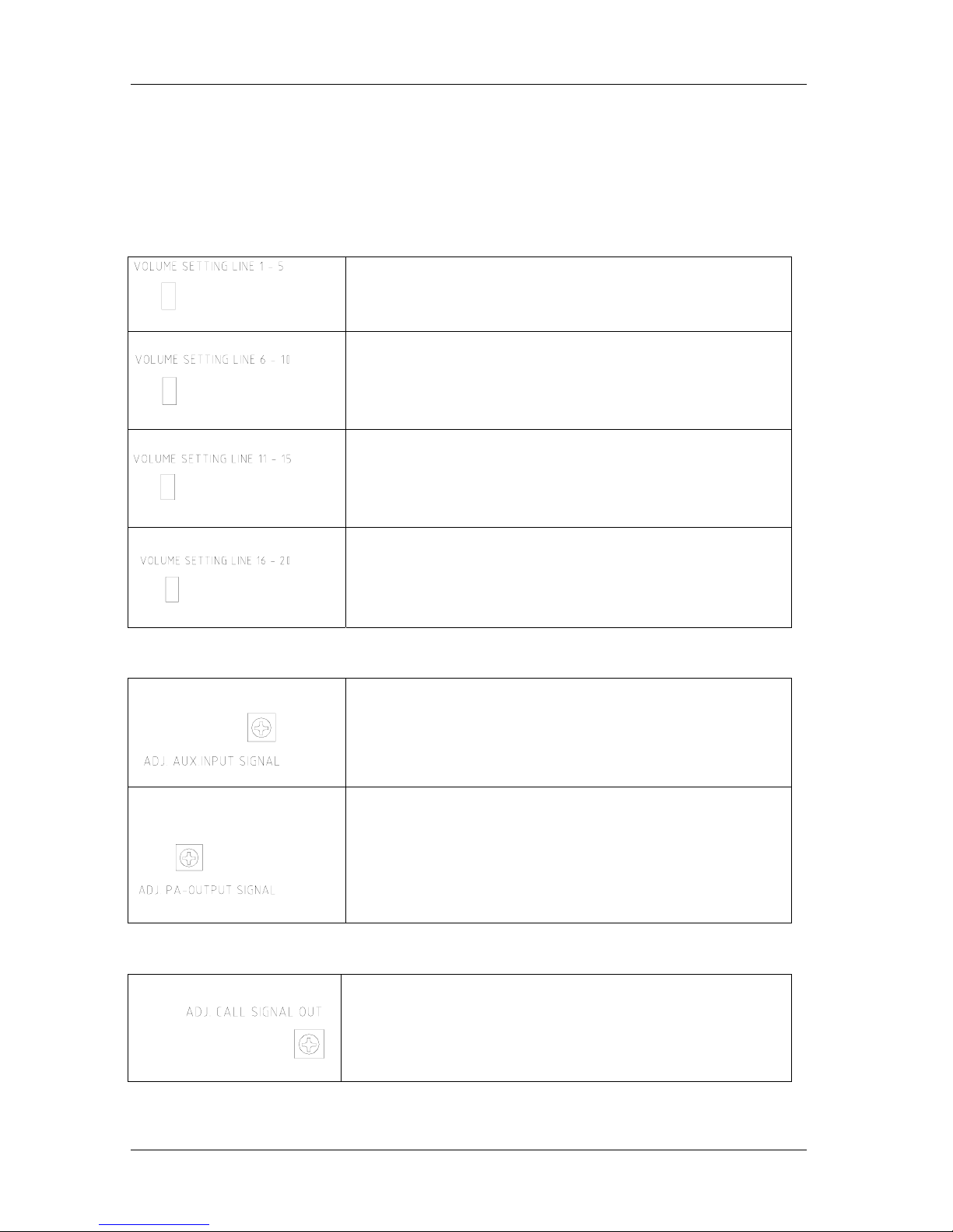
3.8 Volume and signal adjustment.
Ref. drawing CU-10_lo and CU-20_lo for location.
3.8.1 Substations
System volume for substations can be adjusted by separate trim potentiometer for each group of 5 lines.
Market “volume setting line 1-5” “6-10” “11-15” “16-20”
System volume is factory adjusted and does not normally require any adjustment.
Volume adjustment for substation line 1 – 5
Trim potentiometer located on mainboard
Volume adjustment for substation line 6 – 10
Trim potentiometer located on mainboard
Volume adjustment for substation line 11 – 15
Trim potentiometer located on additional board CU-20.
Volume adjustment for substation line 16 – 20
Trim potentiometer located on additional board CU-20.
3.8.2 Auxiliary and Public address.
Signal is factory adjusted and does not normally require any adjustment.
Input signal for auxiliary can be adjusted by separate trim potentiometer
marked “adj. aux.input signal”. Required signal 0dB (0,775V)
Signal for Public address can be adjusted by separate trim potentiometer
marked “adj. pa output signal”.
Signal is factory set to 0dB (0,775V) and does not normally require any
adjustment.
3.8.3 Call signal
Signal is factory adjusted and does not normally require any adjustment.
Level of Call signal out all lines can be adjusted by trim potentiometer
marked “adj. call signal out”
Installation & User Manual System CTB-100V
15
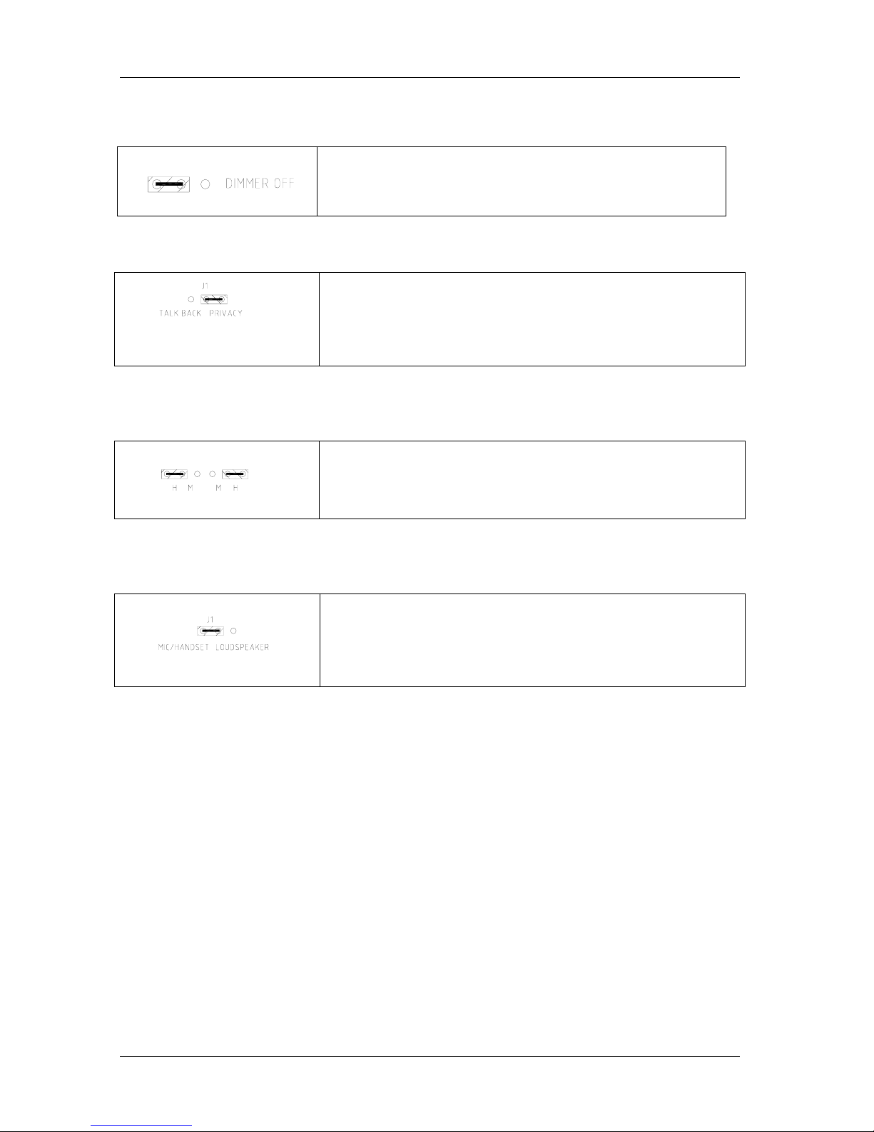
3.9 Dimmer on / off in Operation panel
Ref. drawing CTB-1020_lo
Dimmer can be set to on /off by dip-switch marked “dimmer off”
3.10 Substation STB-1
Default setting is Privacy function, can be set to normal Talk Back
Function.
Talk Back Function; move the jumper J1 on PCB in STB-1
3.11 Substation STB-3
Default setting is for headset, can be set for microphone.
Microphone; move the two jumpers on PCB - STB-3in position M
3.12 Substation STB-5
Default setting is for microphone or handset, loudspeaker can be set to both
loudspeaker and microphone. (Re-entrant speaker)
Re-entrant speaker; move the jumper J1 on PCB in STB-5.
3.13 Installation for C500 Nautical Safety
Installation has to follow strictly requirement given in following chapter and drawings:
• Chapter 2.4.13
• Chapter 3.2.4 and 3.2.6
• Drawing: Cable connection diagram CTB_cc6
Installation & User Manual System CTB-100V
16
4. USER INSTRUCTIONS
4.1 Operation from the operation panel.
Up to 4 operation panels can be connected. Calls can be made from any operation panel to substations.
And calls can be made from any operation panel to another by pressing respective line button.
In this stage the called operation panel act as a substation. Calls from one operation panel will be indicated in
other operation panels. One operation panel is always decided to be a master station with highest priority and can
override operation panels wit h lowe r priority.
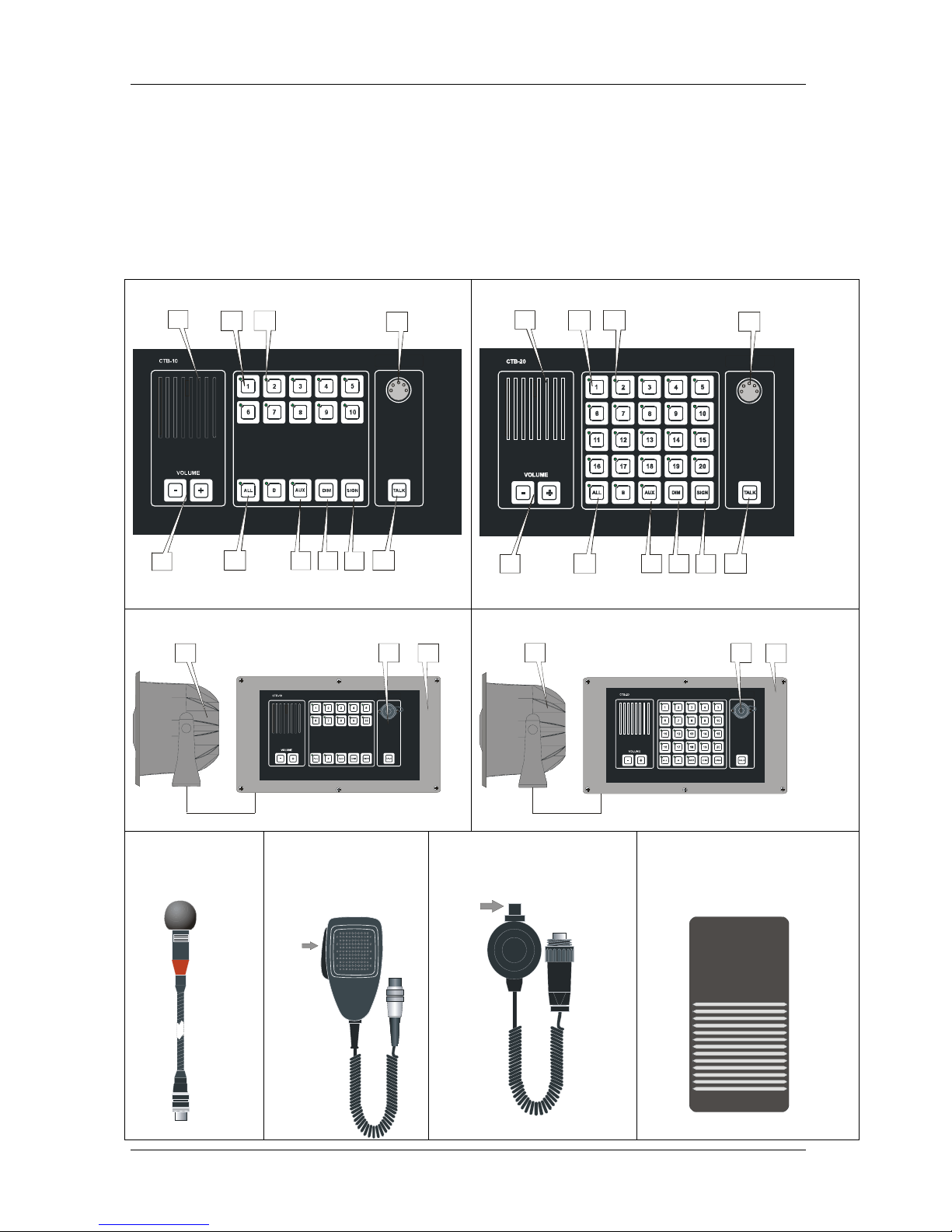
Figure 1 Operation panel CTB-10
1
2
34
11
2
34
1
4
4
212
1
10
9
8
7
6
5
Figure 2 Operation panel CTB-20
1
2
34
11
2
34
1
5
6
7
8
9
10
Figure 3 Operation panel CTB-10W_V01
11
13
12
Figure 4 Operation panel CTB-20W_V01
11
12
13
Figure 5
Gooseneck
microphone
MB-30G
Figure 6
Handheld Microphone
with switch
ETC-1-TB
PTT SWITCH
Figure 7
Handheld Microphone WP
with switch P-66
PTT SWITCH
Figure 8
Footswitch U2410

Installation & User Manual System CTB-100V
17
Figure 1 & 2 CTB-10 & CTB-20
1........Monitor loudspeaker .....For communication and alarm signals.
2........Line Push Buttons ......... Line selection switch with indication light, 1 -10 for CTB-10
.......... ..........................................1 – 20 for CTB-20
3........Green Indication light ... (LED) for each line push button.
4. ......Microphone contact ......For Gooseneck or hand microphone.
5. ......VOLUME - +: ................Increase or decrease of volume in monitor loudspeaker loudspeaker)
6. ......ALL .................................Push button switch with indication light (LED)
7........AUX .................................Push button switch for activating external signal to selected stations.
8. ......DIM .................................Push button switch for adjust intensity of call light in indication light (LED)
9. ......SIGN ............................... Push button switch for signal and activating of extra signal device substations.
10. ....TALK .............................. PTT switch for gooseneck microphone MB-30G
Figure 3 & 4 CTB-10W_V01 & CTB-20W_ V0 1
2-10.. Functions.........................Same as for CTB-10 & CTB-20
11...... External loudspeaker ....For communication and alarm signals. Flush or wall mounting.
.......... ..........................................Monitorloudspeaker not installed.
12...... Microphone contact .......For handheld microphone P-66
13...... Cabinet ........................... WP cabinet, wall mounting only.
Figure 5.......................................Gooseneck microphone MB-30G for CTB-10 & CTB-20.
Figure 6.......................................Handheld microphones ETC-1-TB for CTB-10 & CTB-20.
Figure 7.......................................Handheld microphones P-66 for CTB-10W_V01 & CTB-20W_V01
Figure 8.......................................Footswitch U2410 for handsfree operation of microphone MB-30G
PTT switch = Push To Talk switch LED = Light emitting diode.
Installation & User Manual System CTB-100V
18
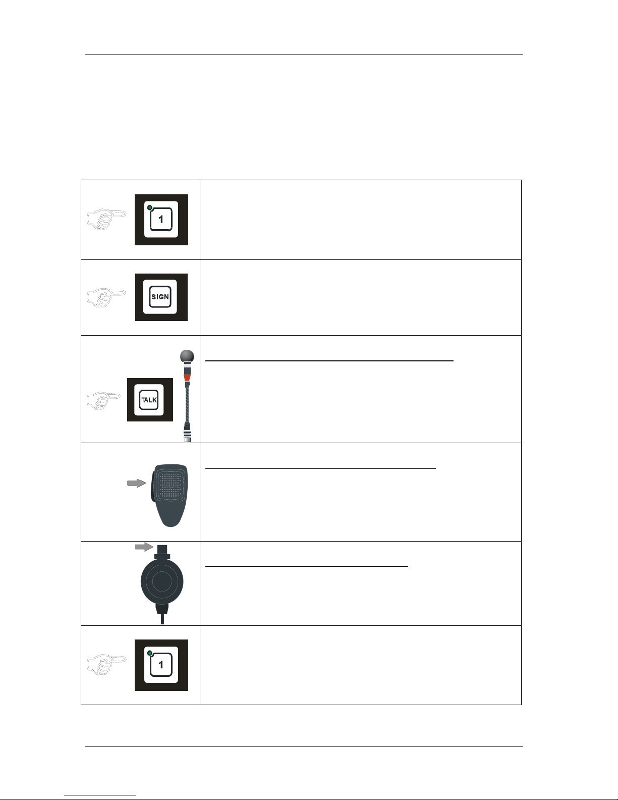
4.1.1 Make a call to an substation.
You can select the substation by pressing desired line push button.
Steady green LED will indicate activated selection.
If desired, the signal button SIGN may be pressed to give a tone signal to selected station. Talk from the operation
panel is performed every time TALK button is pressed. The operation panel unit will be in listening mode as soon
as a station is selected. When communication is finished, press again the selected station button to switch off. The
LED will be switch off to indicate that selected line is turned of.
Operation panel : CTB-10,CTB-20, CTB-10W_V01 or CTB-20W_V01
• Press the LINE button, the call is set up. Indicated by steady green LED
• Press the SIGN button
A tone signal will be given to selected station as long as the SIGN
button is kept pressed.
This will also activate extra signal devices, if connected (Se pos.4.1.5)
Operation panel with gooseneck microphone MB-30G
• Press the TALK button.
Speak clearly into the microphone. When the TALK button is released
the operation panel will be in listening mode, and you will hear the
communication from the selected station.
PTT SWITCH
ETC-1-TB
Operation panel with hand microphone ETC-1-TB
• Press the PTT SWITCH..
Speak clearly into the microphone. When the PTT SWITCH button is
released the operation panel will be in listening mode, and you will hear
the communication from the selected station.
PTT SWITCH
Operation panel with hand microphone P-66
• Press the PTT SWITCH..
Speak clearly into the microphone. When the PTT SWITCH button is
released the operation panel will be in listening mode, and you will hear
the communication from the selected station.
• Press the LINE button once more to end the call.
The LED will be switch off.
Installation & User Manual System CTB-100V
19
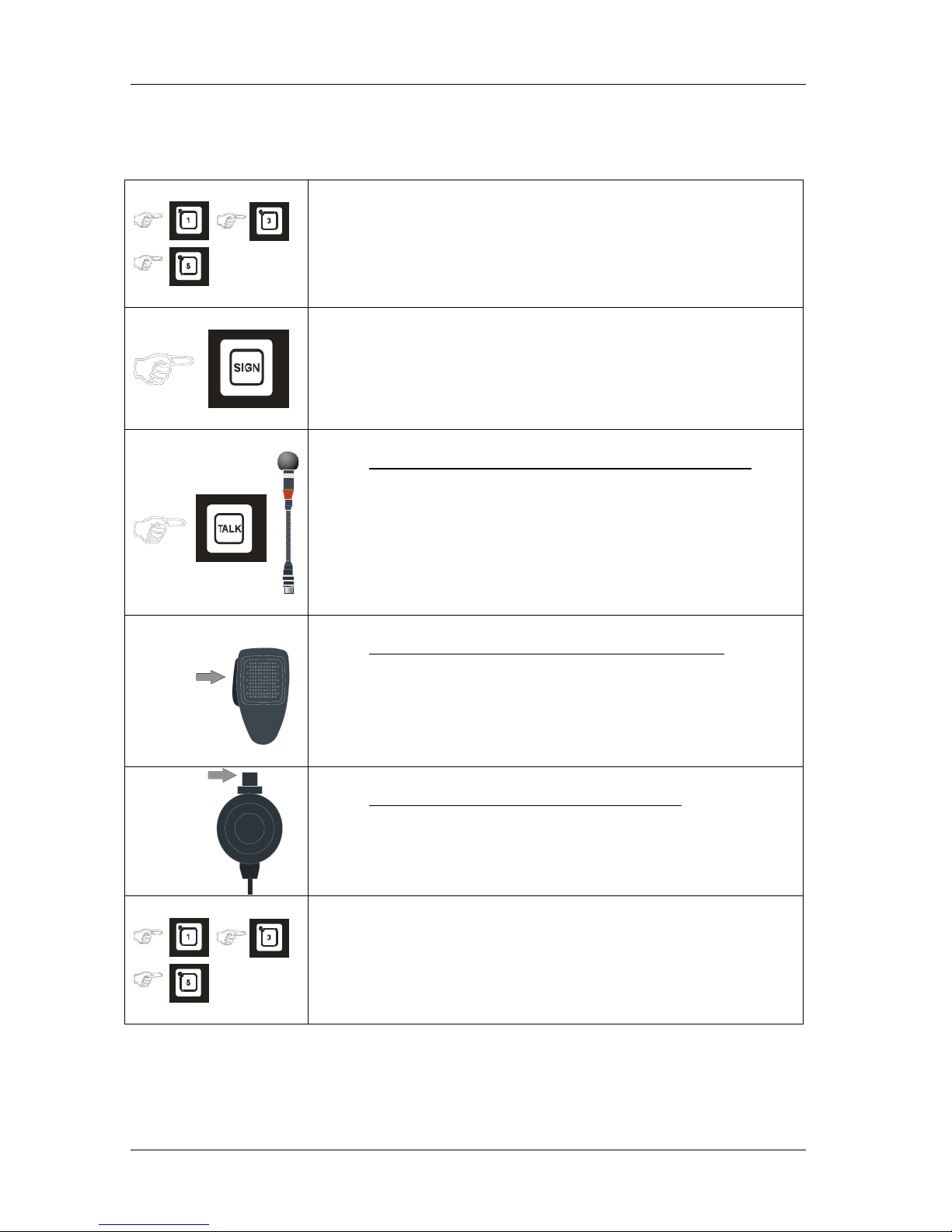
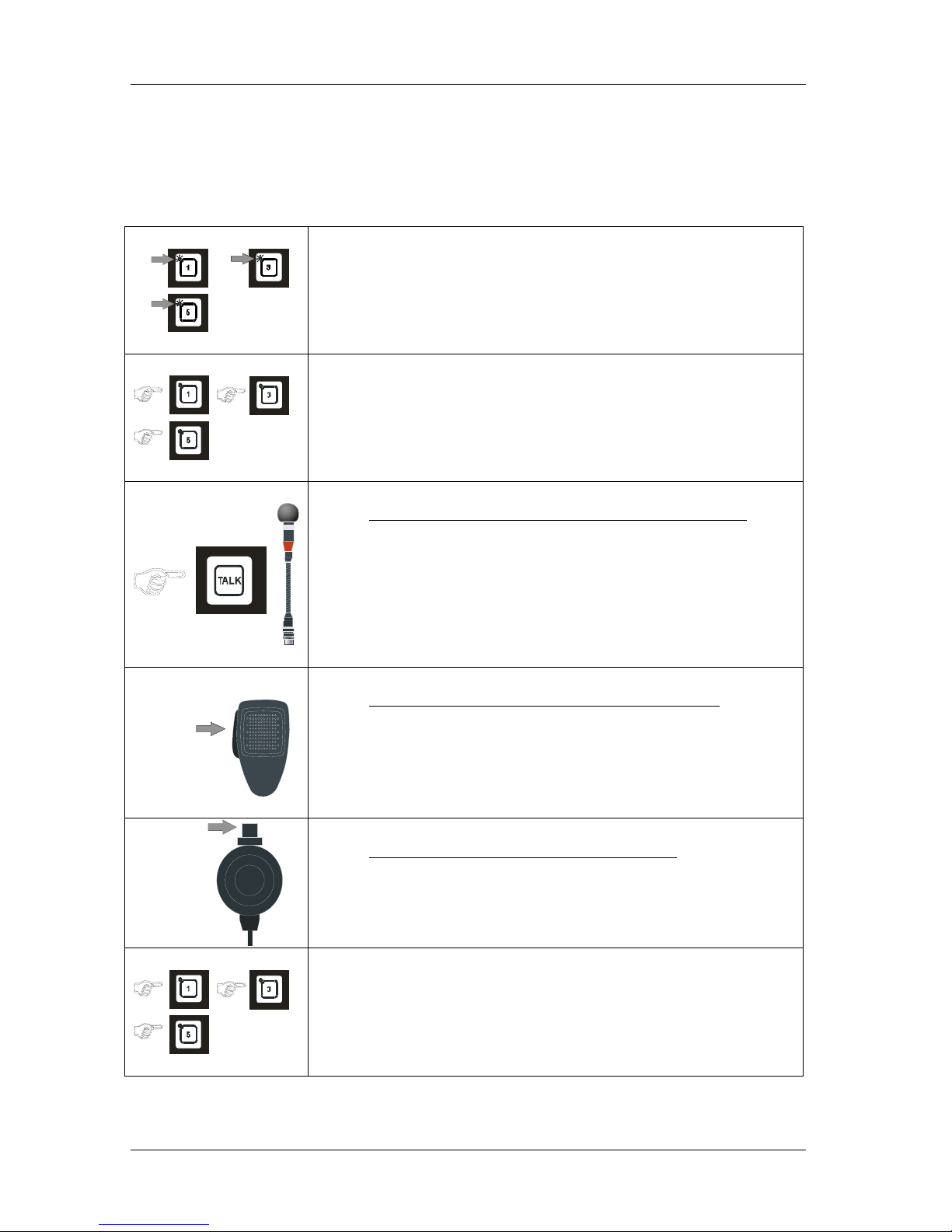
4.1.2 Make a call to group of substations.
You can select group of substations by pressing respective line buttons from one of the four
Operation panels. Only the operation panels can switch off and end the call
• Press the required LINE buttons, the call is set up. Indicated by steady
green LED in selected buttons.
• Press the SIGN button
A tone signal will be given to selected station as long as the SIGN
button is kept pressed.
This will also activate extra signal devices, if connected (Se pos.4.1.5)
Operation panel with gooseneck microphone MB-30G
• Press the TALK button.
Speak clearly into the microphone. When the TALK button is released
the operation panel will be in listening mode, and you will hear the
communication from the selected stations.
PTT SWITCH
ETC-1-TB
Operation panel with hand microphone ETC-1-TB
• Press the PTT SWITCH.
Speak clearly into the microphone. When the PTT SWITCH button is
released the operation panel will be in listening mode, and you will hear
the communication from the selected station.
PTT SWITCH
Operation panel with hand microphone P-66
• Press the PTT SWITCH..
Speak clearly into the microphone. When the PTT SWITCH button is
released the operation panel will be in listening mode, and you will hear
the communication from the selected stations.
• Press all the LINE buttons once more to end the call.
The LED will be switch off.
Installation & User Manual System CTB-100V
20
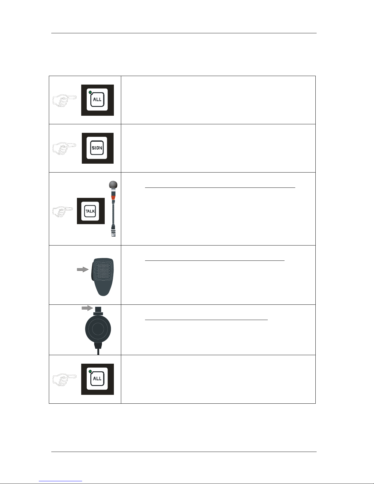
4.1.3 All Call
The message and signal from the operation panel will be given to all substations, as a one-way message.
It will be indicated by steady green LED in the ALL button only. Talk back from substations is closed in this
mode.
• Press the ALL button, the call is set up. Indicated by steady green LED
in the ALL button.
• Press the SIGN button
A tone signal will be given to selected station as long as the SIGN
button is kept pressed.
This will also activate extra signal devices, if connected (Se pos.4.1.5)
Operation panel with gooseneck microphone MB-30G
• Press the TALK button.
Speak clearly into the microphone.
PTT SWITCH
ETC-1-TB
Operation panel with hand microphone ETC-1-TB
• Press the PTT SWITCH.
Speak clearly into the microphone.
PTT SWITCH
Operation panel with hand microphone P-66
• Press the PTT SWITCH..
Speak clearly into the microphone.
• Press the ALL button once more to end the call.
The LED will be switch off.
Installation & User Manual System CTB-100V
21
4.1.4 Handsfree operation
Operation panel with gooseneck microphone MB-30G
and footswitch
• Press the FOOTSWITCH button .
Speak clearly into the microphone. When the TALK button is released
the operation panel will be in listening mode, and you will hear the
communication from the selected station.
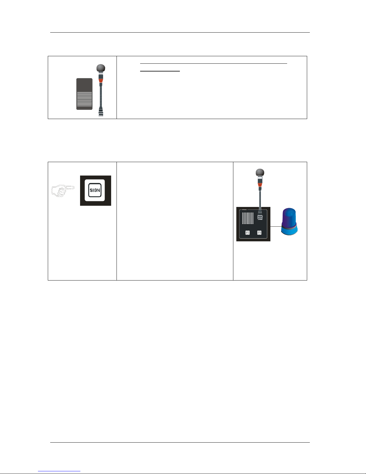
4.1.5 Give signal to substations with extra signal device.
Substation STB-3, STB-5 and STB-5GN is equipped with relay for activating of extra signal device.
Extra signal device can be flashing beacon, rotary light, alarm horn and bells.
Operation panel Substation
• Press the SIGN button
A tone signal will be given to selected
station as long as the SIGN button is
kept pressed:
Indication 1
A tone signal in the substations
monitor loudspeaker
STB-5 and STB-5GN. or in hornloudspeaker for STB-3
This will also activate extra signal to
substations equipped with these
devices:
Indication 2
Signal in flashing beacon, rotary light,
alarm horn or bells.
(STB-5GN w/ Rotary light in
illustration)

Installation & User Manual System CTB-100V
22
4.1.6 Receive a call from an substation.
A call are indicated with flashing green LED in the push button and a beep tone in the monitor loudspeaker or
extern loudspeaker. Will also activate extra signal unit if installed. Only the operationpanel can switch off and end
the call.
• A call is indicated with flashing green LED in for respective line button,
and signal in the monitor loudspeaker.
(and in extra signal unit if installed.)
• Press the LINE button, the call is set up. Indicated by steady green LED
Operationpanel with gooseneck microphone MB-30G
• Press the TALK button.
Speak clearly into the microphone. When the TALK button is released
the operationpanel will be in listening mode, and you will hear the
communication from the selected station.
PTT SWITCH
ETC-1-TB
Operationpanel with hand microphone ETC-1-TB
• Press the PTT SWITCH.
Speak clearly into the microphone. When the PTT SWITCH button is
released the operationpanel will be in listening mode, and you will hear
the communication from the selected station.
PTT SWITCH
Operationpanel with hand microphone P-66
• Press the PTT SWITCH..
Speak clearly into the microphone. When the PTT SWITCH button is
released the operationpanel will be in listening mode, and you will hear
the communication from the selected station.
• Press LINE button once more to end the call.
The LED will be switch off.
Installation & User Manual System CTB-100V
23
4.1.7 Receive a call from two or more substations.
Calls can be received from two or more substations at same time. The operation panel that is set to receive calls
can select between calls from substations.
Calls are indicated with flashing green LED in the push buttons and a beep tone in the monitor loudspeaker
Will also activate extra signal unit if installed. (Only for the first incoming call.)
.
• Calls are indicated with flashing green LED for respective line button,
and signal in monitor loudspeaker.
(And in extra signal unit if installed, Note! only for the first call)
• Press the LINE button, the call is set up. Indicated by steady green LED
The the operation panel can select between substation lines and cancel
calls by pressing the respective LINE button once more.
Operationpanel with gooseneck microphone MB-30G
• Press the TALK button.
Speak clearly into the microphone. When the TALK button is released
the operation panel will be in listening mode, and you will hear the
communication from the selected station.
PTT SWITCH
ETC-1-TB
Operationpanel with hand microphone ETC-1-TB
• Press the PTT SWITCH.
Speak clearly into the microphone. When the PTT SWITCH button is
released the operation panel will be in listening mode, and you will hear
the communication from the selected station.
PTT SWITCH
Operationpanel with hand microphone P-66
• Press the PTT SWITCH..
Speak clearly into the microphone. When the PTT SWITCH button is
released the operation panel will be in listening mode, and you will hear
the communication from the selected station.
• Press the selected LINE buttons once more to end the call.
The LED`s will be switch off.
Installation & User Manual System CTB-100V
24
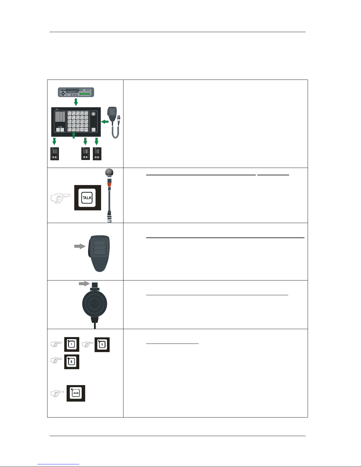
4.1.8 AUX function
An external signal connected to the AUX input of the system, will be transferred to any selected station or group
of stations if the AUX button is selected. (Example: Entertainment and VHF signal.)
Other functions with higher priority will override this function.
AUX
• Press desired line push buttons
• Press the AUX button,
The AUX transferring is set up. Indicated by steady green light.
To override this function with gooseneck microphone
• Press the TALK button on the operation panel.
Speak clearly into the microphone. When the TALK button is released
the system will be in AUX mode again.
PTT SWITCH
ETC-1-TB
To override this function with hand microphone ETC-1-TB
• Press the PTT SWITCH on hand microphone.
Speak clearly into the microphone. When the TALK button is released
the system will be in AUX mode again.
PTT SWITCH
To override this function with hand microphone P-66
• Press the PTT SWITCH..
Speak clearly into the microphone. When the PTT SWITCH button is
released the operation panel will be in AUX mode again.
To end the function
• Press line and AUX button once more to end the transferring.
Installation & User Manual System CTB-100V
25
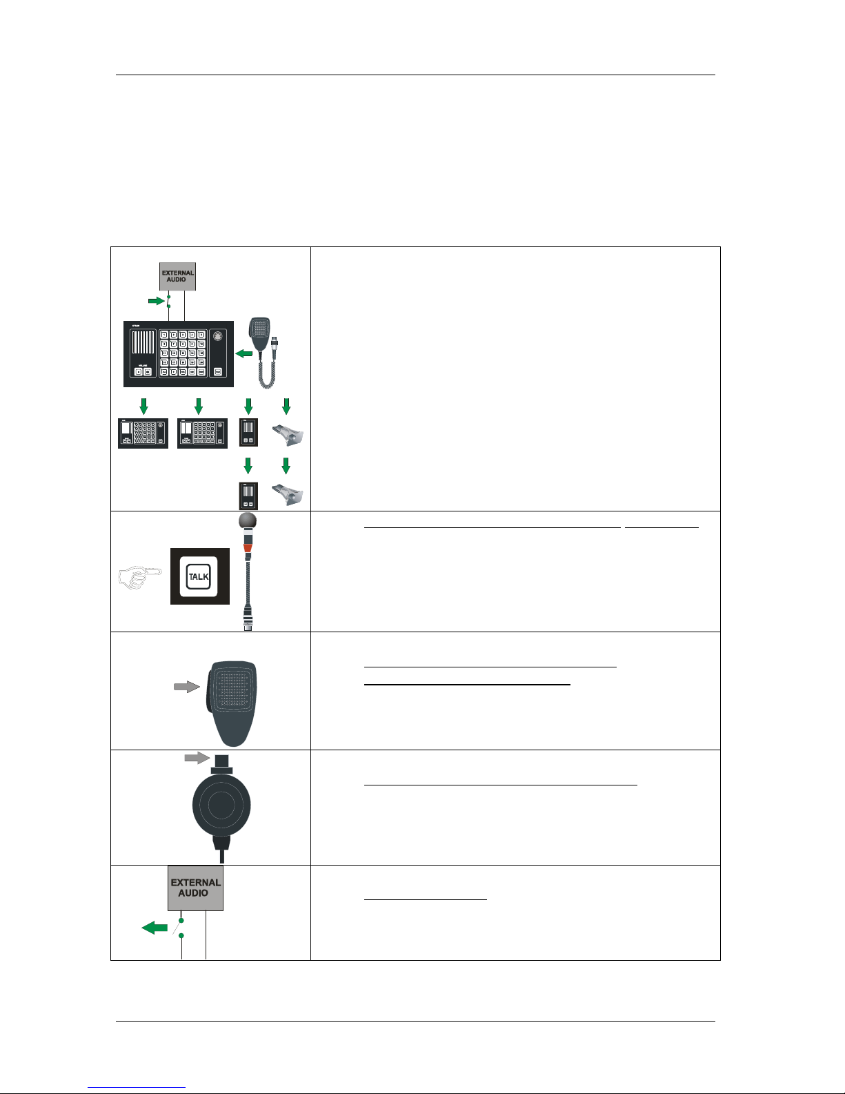
4.1.9 Audio from external audio to All
Alarm (or any audio) from external system can be distributed trough the CTB-100 system.
An potentional free contact and 0dB signal from the external system activate the system and the message will be
addressed to all substations and operation panels.
The talk button on the operation panel or PTT button on hand microphone will override the extern al audio.
Normal talk back functions can not be used in this mode.
External system can be:
• Alarm system.
20
11
4
10
3
2
• Switch on the external audio,
The audio transferring is set up. Indicated by steady green light in
all line push buttons.
To override this function with gooseneck microphone
• Press the TALK button on the operation panel.
Speak clearly into the microphone. When the TALK button is
released the system will be in “audio to all” mode again.
PTT SWITCH
ETC-1-TB
To override this function with ETB-10A
and hand microphone ETC-1-TB
• Press the PTT SWITCH on hand microphone.
Speak clearly into the microphone. When the TALK button is
released the system will be in “audio to all” mode again.
PTT SWITCH
Operationpanel with hand microphone P-66
• Press the PTT SWITCH..
Speak clearly into the microphone. When the PTT SWITCH
button is released the operation panel will be in “audio to all”
mode again.
To end the function
• Switch off the external audio.

Installation & User Manual System CTB-100V
26
4.1.10 Public Address Operation of external system
The four last line push buttons on the operation panels can be set to access 1 to 4 public address zones.
CTB-10 & CTB-10W_V01: Push button marked 7-8-9- 10
CTB-20 & CTB-20W_V01: Push button marked 17-18-19-20
ALL button will access “all” inclusive Public Address Operation. Operation panel with higher priority will
override ongoing PA-message
CTB-10 & CTB-10W_V01
CTB-20 & CTB-20W_V01
• Press desired LINE button (s), the Public Address call is set up.
Indicated by steady green LED.
Single or group of zones
Operation panel with gooseneck microphone MB-30G
• Press the TALK button.
Speak clearly into the microphone for giving the message.
PTT SWITCH
ETC-1-TB
Operation panel with hand microphone ETC-1-TB
• Press the PTT SWITCH..
Speak clearly into the microphone for giving the message.
PTT SWITCH
Operation panel with hand microphone P-66
• Press the PTT SWITCH..
Speak clearly into the microphone for giving the message.
•
CTB-10 & CTB-10W_V01
CTB-20 & CTB-20W_V01
To end the function
• Press line button (s) or ALL once more to end the Public Address
Operation
Installation & User Manual System CTB-100V
27
4.1.11 Emergency Public Address Operation.
In order to comply with PA-requirements, two PA call stations are required: The CTB-100V system are designed
for use with up to four operation panels that can be used as Emergency call stati ons. I n ad di t i on o ne or more All
call station (Ex. Lifeboat stations) can be used as Emergency call stations.
Following functions:
• Mute of the External Alarm System (General / Fire Alarm)
• Operation panel with 1
st
priority, normally bridge, can override other operation panels.
Type of Operation panels/ Emergency call stations:
• CTB-10 Operation panel 10 line selection, in do o r use. Hand or gooseneck microphone.
• CTB-10W/V01 Operation panel 10 li ne selection, WP. Handmicrophone onl y.
• CTB-20 Operation panel 20 line selection, in do o r use. Hand or gooseneck microphone.
• CTB-20W/V01 Operation panel 20 li ne selection, WP. Handmicrophone onl y.
• VMT-603 All call station WT with handmicrophone.
Central unit CU-200
ON
OFF
VPA-120
POWER AMPLIFIER
100V POWER AMPLIFIER
From 1 of 4 operation panels.
• Press the ALL button, the call is set up. Indicated by steady green LED
in the ALL button.
“EMERGENCY PABUTTON”
With gooseneck microphone MB-30G CTB-10 & CTB-20
• Press the TALK marked “EMERGENCY PA –BUTTON.”
• Speak clearly into the microphone to give message.

Installation & User Manual System CTB-100V
28
With hand microphone ETC-1-TB (CTB-10 & CTB-20)
• Press the PTT SWITCH marked “EMERGENCY PA-BUTTON”
• Speak clearly into the microphone to give message.
With hand microphone P-66 (CTB-10W_V01 & CTB 20W_V01)
• Press the PTT SWITCH marked “EMERGENCY PA-BUTTON”
• Speak clearly into the microphone to give message.
• Press the ALL button once more to end the PA-call.
The LED will be switch off.
From All call station VMT-603
• Press the PTT SWITCH marked “EMERGENCY PA-BUTTON”
Speak clearly into the microphone to give message.
The operation will mute the External Alarm System (General / Fire
Alarm)
• When the PTT SWITCH button is released the CTB-100 system will
be back in normal Talk back mode.

Installation & User Manual System CTB-100V
29
4.1.12 Volume
By pressing + or - buttons repeatedly, you can increase or decrease the listening volume in the ETB.
This will also affect the volume for a parallel speaker connected to the ETB
• Press the + buttons repeatedly for increase volume
• Press the - buttons repeatedly for decrease volume
4.1.13 Dimming of call light.
Intensity of light in push buttons can be adjusted by pressing DIM button.
Switch between two steps max.and 1/3. Default is set to max.
Dimmer can be set to on /off by dip-switch marked “dimmer off” (See chapter 3.10)
• Press DIM button once for 1/3 intensity.
• Press DIM button once more back to max. intensity.

Installation & User Manual System CTB-100V
30
4.2 Parallel communication
Function with operation from parallel microphone / loudspeaker located on bridge wings,
or other locations near the operation panel, where parallel microphone / loudspeaker needed.
Two parallel stations can be connected. Communication is set up by the operationpanel.
Bridge wing unit will be in operation mode as soon as a station is selected on the operationpanel.
Figure 9 Parallel station STB-6 Figure 10 Parallel station STB-6GN
3
P
T
T
S
W
I
T
C
H
1
2
1. (Parallel to the central unit)
2. For microphone
3.
PTT switch = Push to talk button switch
Loudspeaker
Contact
Microphone ETC-1-TB with PTT switch
3
2
1
1. (Parallel to the central unit)
2. PTT switch for microphone
3.
PTT switch = Push to talk button switch
Loudspeaker
TALK
(Parallel to the central unit)
(Parallel to PTT switch )Footswitch
Figure 10 Parallel station SB-4
P
T
T
S
W
I
T
C
H
1
2
3
1. (Parallel to the central unit)
2. For microphone
3.
PTT switch = Push to talk button switch
Loudspeaker
Contact
Microphone Microphone P-66 with push to talk switch
(parallel to microphone on the central unit

Installation & User Manual System CTB-100V
31
4.2.1 Operation
Note! Line selection and signal have to be set up from the central unit.
Operationpanel
• Press the desired LINE button, the call is set up. Indicated
by steady green LED
Operationpanel
• Press the SIGN button.
A tone signal will be given to selected station as long as the
SIGN button is kept pressed.
This will also activate extra signal to substations equipped
with these devices.
Figure 7 Parallel station STB-6
P
T
T
SW
I
T
CH
• Press PTT SWITCH on hand microphone ETC-1-TB
Speak clearly into the microphone. When PTT SWITCH
button is released the parallel equipment will be in listening
mode, and you will hear the communication from the
selected station in the monitor loudspeaker.
Figure 8 Parallel station STB-6GN
• Press TALK on the STB-6GN
Speak clearly into the microphone. When TALK button is
released the parallel equipment will be in listening mode,
and you will hear the communication from the selected
station in the monitor loudspeaker.
STB-6GN Hands free operation
• Press the FOOTSWITCH button .
Speak clearly into the microphone. When the TALK button
is released the parallel equipment will be in listening mode,
and you will hear the communication from the selected
station.
Figure 9 Parallel station SB-4
P
T
T
S
W
I
T
C
H
SB-4 Plug box P-66 microphone. VML-1520 loudspeaker
• Press PTT SWITCH on hand microphone P-66
Speak clearly into the microphone. When PTT SWITCH
button is released the parallel equipment will be in listening
mode, and you will hear the communication from the
selected station.
Operationpanel
• Press the desired LINE button on the operationpanel once
more to end the call.
The LED will be switch off.

Installation & User Manual System CTB-100V
32
4.3 Operation from substations.
Calls can be made from substations to the operation panels by pressing the CALL push button. A call is indicated
by a flashing green LED and a signal in the operation panel. The operation panel confirm the call by pressing
respective line button. The communication is set up. Only the operation panel can switch off and end the call.
Figure 11 Substation STB-1
1
2
3
1. Re-entrant
For communic ation fr om the centr a l unit.
Microphone for comm unica tion to the central un it.
2.
Push button switch for call to central u nit.
3.
PTT switch for talk to th e central unit
PTT sw itch = Push to talk but ton sw itc h
Loudspeaker
CALL
TALK
Figure 12 Substation STB-2
1
2
1.
Push button switch for call to central unit.
2
CALL
.
For communication from the central unit.
Microphone for communic a t i on t o t he central unit.
Re-entrant Loudspeaker
Figure 13 Substation STB-3
1
1
2
10m cable
6
5
3
4
PTT SWITCH
1. For headset or Microphone.
2. Push button switch for call to central unit.
3. For communication from the central unit.
4.
5. P-MT7 with boom microphone
6. P-66 with PTT switch
Contact
Call
Loudspeaker
Headset
Microphone
Signal device Activated from the central unit.
PTT switch = Pus h to talk button
.

Installation & User Manual System CTB-100V
33
Figure 14 Substation STB-5
PTT SWITCH
P
T
T
S
WI
T
C
H
6
2
3
5
4
1
1. For communication from the central unit.
2. Push button switch for call to central unit.
3. C For handset HAS-1 or handheld microphone ETC-STB5
4. HAS-1 with push to talk switch (PTT)
5. ETC-STB5 with push to talk switch (PTT)
6. Activated from the central unit.
PTT switch = Push to talk button switch
Loudspeaker
Call
ontact
Handset
Microphone
Signal device
Figure 15 Substation STB-5GN Figure 16 Substation HE-112M
1
2
3
4
1. For communication from the central unit.
2. Push button switch for call to central unit.
3. PTT switchfor talk to the central unit.
4. Activated from the central unit.
PTT switch = Push to talk button switch
Loudspeaker
CALL
TALK
Signal device
1
2
1.
For communication from the central unit.
Microphone for communication to the central unit.
2.
Push button switch for call to central unit.
Re-entrant Loudspeaker
CALL

Installation & User Manual System CTB-100V
34
Figure 17 Substation VH-10M Figure 18 Substation VHM-10
10m cable
1
2
1.
CD-2 for VH-10M
2.
Push button switch for call to the centra l unit
3.
For communication from the central unit
Microphone for communication to the centra l unit.
Plugbox
CALL
Re-entrant Loudspeaker
3
PTT SWITCH
1
3
2
1. For communic ation from the centra l unitLoudspeaker
2. Push button switch for call to the central unit
3. P-66 fixed connected with PTT switch
PTT switch = Push to talk button switch
CALL
Microphone
CABINET
Figure 19 Substation NEBB-42EX / EX Loudspeaker
EEx de IIC T6 PTB Nr.Ex-87.B .1009
Ui 690V
CEAG
GHG 411
IN 16A
1
2
1. Push to call switch
2. Re-entrant Loudspeaker EX.

Installation & User Manual System CTB-100V
35
4.3.1 Operation from STB-1
Substation Operationpanel
• Press the CALL button.
• Indicated with flashing green LED
and a signal in the operation panels
speaker for selected line.
• Operator of the operation panel press
respective LINE button, the call is set
up. Indicated by steady green light,
Loudspeaker
• Press TALK button .
• Speak clearly into the re-entrant
loudspeaker. When TALK button is
released the STB-1 will be in listening
mode, and you will hear the
communication from the operation
panel.
• Operator of the operation panel end
the call by pressing the LINE button
once more .
4.3.2 Operation from STB-2
Substation Operationpanel
• Press the CALL button.
• Indicated with flashing green LED
and a signal in the operation panels
monitor loud speaker for selected line.
• Operator of the operation panel press
respective LINE button, the call is set
up. Indicated by steady green light in
the operation panel
• Speak clearly into the
re-entrant loudspeaker for
communication to the operation panel,
and receive communication in the same
loudspeaker.
• Operator of the operation panel end
the call by pressing the LINE button
once more .

Installation & User Manual System CTB-100V
36
4.3.3 Operation from STB-3
Substation Operationpanel
• Press the CALL button.
• Indicated with flashing green LED
and a signal in the operation panels
speaker for selected line.
• Operator of the operation panel press
respective LINE button, the call is set
up. Indicated by steady green light.
With headset P-MT7
10m cable
• Speak clearly into the
Boom microphone on the headset
• Receive communication from the
operation panel in the headphones.
(And in the loudspeaker if installed)
• Operator of the operation panel end
the call by pressing the LINE button
once more .
With microphone P-66
PTT SWITCH
• Press the PTT SWITCH on the
microphone.
Speak clearly into the microphone.
When PTT SWITCH button is
released the microphone will be in
listening mode, and you will hear the
communication from the operation
panel in the loudspeaker
• Operator of the operation panel end
the call by pressing the LINE button
once more .

Installation & User Manual System CTB-100V
37
4.3.4 Operation from STB-5
Substation Operationpanel
• Press the CALL button .
• Indicated with flashing green LED
and a signal in the operation panels
monitor loud speaker for selected line.
• Operator of the operation panel press
respective LINE button, the call is set
up. Indicated by steady green light,
With microphone
PTT SWITCH
ETC-STB
5
Loudspeaker
• Press the PTT SWITCH on the
microphone and speak clearly into the
microphone.
• When PTT SWITCH is released the
STB-5 will be in listening mode, and
you will hear the communication from
the operation panel in the monitor
loudspeaker.
• Operator of the operation panel end
the call by pressing the LINE button
once more .
With handset HAS-1
PTT SWITCH
• Press the PTT SWITCH on the
handset and speak clearly into the
microphone.
• When PTT SWITCH is released the
STB-5 will be in listening mode, and
you will hear the communication from
the operation panel in the handsets
loudspeaker
• Operator of the operation panel end
the call by pressing the LINE button
once more .
With monitorspeaker only
Loudspeaker
• Speak clearly into the
Monitor loudspeaker for
communication to the operation panel,
and receive communication from the in
the same loudspeaker.
• Operator of the operation panel end
the call by pressing the LINE button
once more .

Installation & User Manual System CTB-100V
38
4.3.5 Operation from STB-5GN
Substation Operationpanel
• Press the CALL button.
• Indicated with flashing green LED
and a signal in the operation panels
speaker for selected line.
• Operator of the operation panel press
respective LINE button, the call is set
up. Indicated by steady green light,
Loudspeaker
• Press TALK button on the STB-5GN
Speak clearly into the microphone.
When TALK button is released the
STB-5GN will be in listening mode,
and you will hear the communication
from the selected station in the monitor
loudspeaker.
• Operator of the operation panel end
the call by pressing the LINE button
once more .
4.3.6 Operation from HE-112M / HE-112MT
Substation Operationpanel
• Press CALL button.
• Indicated with flashing green LED
and a signal in the operation panels
speaker for selected line.
• Operator of the operation panel press
respective LINE button, the call is set
up. Indicated by steady green light.
Loudspeaker
• Speak clearly into the
Re-entrant loudspeaker for
communication to the operation panel,
and receive communication in the same
loudspeaker.
• Operator of the operation panel end
the call by pressing the LINE button
once more .

Installation & User Manual System CTB-100V
39
4.3.7 Operation from VH-10M / VH-10M-T
Substation Operationpanel
• Press CALL button.
• Indicated with flashing green LED
and a signal in the operation panels
speaker for selected line.
• Operator of the operation panel press
respective LINE button, the call is set
up. Indicated by steady green light in
the operation panel.
• Speak clearly into the
Re-entrant loudspeaker for
communication to the operation panel,
and receive communication in the same
loudspeaker.
• Operator of the operation panel end
the call by pressing the LINE button
once more .
4.3.8 Operation from VHM-10 / VHM-10-T
Substation Operationpanel
• Press the CALL button.
• Indicated with flashing green LED
and a signal in the operation panels
speaker for selected line.
• Operator of the operation panel press
respective LINE button, the call is set
up. Indicated by steady green light,
PTT SWITCH
• Press the PTT SWITCH.on the
microphone. Speak clearly into the
microphone. When PTT SWITCH is
released the VHM-10 will be in
listening mode, and you will hear the
communication from the operation
panel in the loudspeaker.
• Operator of the operation panel end
the call by pressing the LINE button
once more .

Installation & User Manual System CTB-100V
40
4.3.9 Operation from NEBB-42EX / EX Loudspeaker
Substation Operationpanel
• Press the CALL button.
• Indicated with flashing green LED
and a signal in the operation panels
speaker for selected line.
• Operator of the operation panel press
respective LINE button, the call is set
up. Indicated by steady green light in
the central unit
• Speak clearly into the
re-entrant EX loudspeaker for
communication to the operation panel,
and receive communication from the
central unit in the same loudspeaker.
• Operator of the operation panel end
the call by pressing the LINE button
once more .

Installation & User Manual System CTB-100V
41
5. COMMISSIONING
5.1 General
The CTB and CU- units and all sub equipments have been fully tested in our workshop before delivery. To ensure
that everything is correct after installation and configuration of the system, do the following procedure before the
system is ready for use.
Ref. is made to Chapter 3 Installation and configuration procedures and installation drawings.
5.2 Mechanical Inspection
• All equipment is well fastened in console or wall according to pos. 3.2
• All cable and cable glands are well tight and fastened according to pos. 3.2
5.3 Cable Inspection
All cables are connected according to chapter pos.3.3 and dwg.no. CTB-100_cc1, CTB-100_cc2, CTB-100_cc3,
CTB-100_cc4 and CTB-100_cc05
• It is used signal cables 0,75mm
2
approved ship-cable of type twisted pair with outer braided copper
screen.The screens are interconnected in junction boxes and grounded in the central unit only
(CU-100,CU-200)
Common ground points:
Terminal block X8-1-20 /no. 5 is ground point for each substation,
Terminal block X1,2,3,4 / no.11 is ground poi nt fo r eac h o perat ion panel.
• Power cable are 1,5mm
2
and is connected to terminal block X7, + to terminal 1, - to terminal 2.
The screen is grounded on terminal 3.
• It is used cable 1,5mm
2
for power to signal units.
• Polarity for extra signal device is connected in according to dwg.CTB_cc3 and CTB_cc4
5.4 Check Configurations.
Ref. Chapter 3 Installation and configuration procedures
• It`s used power supply according to 3.4
• Priority is set according to pos. 3.5
• Receive call from substation is set according to pos. 3.6
• Public address zones is set according to pos. 3.7
• Volume and signal adjustment is set according to pos. 3.8
• Dimmer is set according to pos. 3.10
• Substation is set according to 3.11, 3.12 and 3.13
5.5 C500 Nautical Safety
For complying to DNV ship requirements-following is carried out:
• Configuration and connection are according to chapter 2.4.13 and cable connection drawing CTB_cc6
• Sound pressure level is set to satisfactory audibility and volume, ref. chapter 3.8.1
• A sign plate with directory / substation number for all substations has been placed close to the CTB panel
• A sign plate with each substation number has been placed on or close to each substation.

Installation & User Manual System CTB-100V
42
5.6 Starting up the system.
The system has no On/Off switch for main power. Power switching is done from external equipment
The system is always powered and ready for use and it’s only indicated when using the system.
Following procedure has to be completed before end use. Do the test procedure for all equipments in the
installation. Test functions according to User Instructions in Chapter 4.
Basic functions CTB, operation from all CTB-operation panels have to be done.
Pos. Operation Requirement Tested, ok
1 Commi ssi oni n g according to chapter 5.2, 5,3, 5.4 and 5.5 i s don e .
2 Power on. 24V DC measured on terminal X7 no.1-2 in central unit
3 Make a call to each substation Ref. 4.1.1
4 Make a call to group of substations Ref. 4.1.2
5 All Call Ref. 4.1.3
6 Give signal to substations with extra signal device. 4.1.5
7 Receive a Call from an substation Ref. 4.1.6
8 Receive a Call from two or more substations. Ref. 4.1.7
9 Volume control of internal loudspeaker Ref. 4.1.12
10 Dimmer for light in Line button Ref. 4.1.13
Additional functions if installed
Pos. Operation Requirement Tested, ok
11 Make a call with footswitch, hands free. Ref. 4.1.4
12 AUX function Ref. 4.1.8
13 Audio from external system Ref. 4.1.9
14 Public Address operation of external system Ref. 4.1.10
15 Emergency Public Address operation Ref. 4.1.11
Parallel communication / Bridge wing Ref. 4.2.1, if installed
Pos. Operation Requirement Tested, ok
16 Operation with STB-6
17 Operation with STB-6GN
18 Operation with STB-6GN hands free
19 Operation with SB-4
20 Call to two or more substations from parallel station
Power supply SPS-4, If installed
Pos. Operation Requirement Tested, ok
21 Operating by 230V AC or 115 v AC mains power supply.
24V DC on terminal 3 -4 Green light marked “DC ok”
22 Operating with 24V DC emergency power supply.
1. Disconnect 230V AC or 115V AC mains power supply and check if
the auto switch relay switch to emergency 24V DC. 24V DC on
terminal 3 -4
Check if power failure contact marked NC 6-7 is activated.
2. Disconnect cables to + and – on the power supply module, and
check if the auto switch relay switch to emergency 24V DC. On
terminal 3 -4
Check if power failure contact marked NC 6-7 is activated.
Substations
Pos. Operation Requirement Tested, ok
23 Operation from STB-1 Ref. 4.3.1
24 Operation from STB-2 Ref. 4.3.2
25 Operation from STB-3 Ref. 4.3.3
26 Operation from STB-5 Ref. 4.3.4
27 Operation from STB-5GN Ref. 4.3.5
28 Operation from HE-112M Ref. 4.3.6
29 Operation from VH-10M Ref. 4.3.7
30 Operation from VHM-10 Ref. 4.3.8
31 Operation from NEBB-42EX / EX Loudspeaker Ref. 4.3.9

Installation & User Manual System CTB-100V
43
Volume control
Pos. Operation Requirement Tested, ok
32 Adjust sound pressure level, to convenient level if necessary
Master volume line 1-5, 6-10, 11-15, 16-20
Ref. chapter 3.8 and dwg.CU-100:lo and CU-2 0 0_lo
5.8 Trouble shooting.
Most faults can be related to following problems
Important! Use this trouble shooting together with chapter 3 Installation an d Co nfig uration Proce dure
Problems when operating from operation panels.
Pos. Failure event Description / Indication Recommended Action
No voltage measured on terminal block
X7 no.1-2 in the CU-u nit
1.Check 24V DC mains power
supply or power supply SPS-4
1
The whole system is shut
down.
No light indication in CTBpanels.
Correct voltage 24 – 32VDC measured
on terminal block X7 no.1-2 in the CUunit
2. Check fuse marked F3 1AT
(Ref. dwg CU-100_lo)
2
SPS-4 power supply failure Indication from failure contact X2
No.5-6(NO)or. X2 No.6-7 (NC)
No light in “DC ok”
Two possibilities
1. 230V AC or 115V AC failed and
have been switched to 24V DC
Emergency.
2.The power supply module has failed.
1. Check main power supply
2. Check fuse 5.0AT , terminal
marked 3
2.1 If not success, the power
module have to be repaired./
replaced.
3 Operation from CTB-panels
failed 1.
No audio message received in any
substation no. 1-10 or 11-20.
Check fuse marked “fuse 2”1.0AT
for line 1-10 and “fuse 4”1.0AT
for line 11-20
3.1 Operation from CTB-panels
failed 2
One or more operation panels failed.
One or more Indication light is active ,
one for each operation panel marked
“indication for panels” on central
unit.ref.dwg.CU-100_lo
Check all connection for actual
panel(s) The panel operate correct
when light is turned off.
Try to replace the position, if
current panels then work correct
the fault must be in the central
unit. The main board have to be
replaced or repaired.
4 Priority do not fulfil
requirement for actual
operation panel
Check if DIP switches in the
central unit marked “set priority”
is set according to chapter 3.5
5 Receive call from substation
do not fulfil requirement for
actual station.
Check if DIP switches in the
central unit marked “set receive
call” is set according to chapter
3.6
6 Public address operation does
not fulfil the requirement for
operation of SPA public
address system.
Check if DIP switches in the
central unit marked “selector for
PA-zones” is set according to
chapter 3.7
7 Level for signal from auxiliary
does not fulfil the requirement.
Adjust trim potentiometer in the
central unit marked “adj. aux.
input signal” to satisfactorily
level.see chapter 3.8.2
7.1
Level for output PA-Signal
does not fulfil the requirement.
Adjust trim potentiometer in the
central unit marked “adj. PAoutput signal” to satisfactorily
level. See chapter 3.8.2

Installation & User Manual System CTB-100V
44
7.2 Level for call signal out to all
lines does not fulfil the
requirement.
Adjust trim potentiometer in the
central unit marked “adj. call
signal out” to satisfactorily level.
See chapter 3.8.3
8 General operating problems
occurred when operating
several stations.
Instability. Check cable and termination
blocks in the CU unit for
respective stations. And especially
cable and termination blocks in
junction boxes, if used.
9 One substation can not be
operated
No contact between CTB panel and
substation
Check cable and terminal block in
the CU unit for current extension.
Check cable and terminal block in
the substation or plugbox. Move
this terminal block to a another
ext. number.
If operating is ok, current
substation have to be repaired.
10
Operation problem from an
substation.
Continuous rapping tone (pip..pip) in
the CTB units.
Change polarity in substation
terminal no1-2
11 No signal in substation when
using the sign push button on
the CTB- unit.
No audio 1Khz tone in the substation Disconnect the substation.
1. If 7V AC is measured on
terminal X8 1-2 in the CU unit,
this unit is ok.
2. If no voltage measured, the CU
unit have to be repaired
3. Connect the substation.
If no voltage measured on
terminal X8 1-2 in substation,
fault must be in cable or the
substation have top be repaired.
12
No signal in additional signal
device when using the sign
push button.
Signal in substation, but no signal in the
additional signal device.
Disconnect the substation.
1. If no voltage measured on
terminal X8 3-4 in the CU unit,
check fuse F3 1A.
2. If fuse F3 is ok.
Check automatic fuse by waiting
2-3 sec. If 24V DC is measured,
the load is to high Max. 50mA.
13
Feedback problems In one CTB unit Move substation or parallel
equipment to another position.
14
Problems with system
generated noise 1
Occurred both in central unit and
substations if it used ships own 24V DC
Disconnect ships 24V DC and
connect a separate power supply
(SPS-4) or a DC 24V / 24V DC
converter.
14.1 Problems with system
generated noise 2
Occurred both in CTB units and
substation, (substations)
1. Check all cable connections,
especially the screens. Important
that connections is done according
to requirements in chapter3.4 and
dwg.CTB-100_cc1, CTB-100_cc2
CTB-100 _cc3, CTB-100 _cc4,
CTB-100_cc5, CTB_cc2,
CTB_cc3 and CTB_cc6
2. If still problems, try with an
capacitor 1uF between terminal
no.1-2 block X8-10 (20)
If still problems, it will require
service from Zenitel.

Installation & User Manual System CTB-100V
45
Problems when operating from substation or parallel station connected to an operation panel
Pos. Failure event Description / Indication Recommended Action
15 Operation from an substation
can not be done
No flashing green LED and a signal in
the CTB monitor loudspeaker for the
selected line.
1. Check cable and terminal block
in the substation or plug box.
2. Move this terminal block to a
another ext. number.
If still problems, the substation
have to be repaired
If operating is ok, the CU unit
have to be repaired
16 Problems with high
background sound
Nearby the substation Replace current substation with
substation with headset or with
external loudspeaker STB-2
Or adjust Master volume line 1-5
6-10, 11-15 or 16-20. (Ref.
Document dwg.CU-100_lo and
CU-200_lo)
17 Operation from an parallel
station can not be done
Normal operation from the CTB unit. 1. Check cable and connections
between the parallel station and
the central unit.
2. Check microphones
If still problems, the parallel
station have to be repaired
Problems when operating from All call stations. Ref DNV C500 Nautical Safety
Pos. Failure event Description / Indication Recommended Action
18 Operation from one all call
station can not be done.
No audio in all other operation panels or
substations.
1. Check connection between the
unit and the junction box.
2. If 24V DC voltage is measured
in the all call station, the unit have
to be repaired. Ref. dwg. CTB-cc6
19
20
Operation from all
all call
station can not be done.
No audio in all other operation panels or
substations.
1. Check connection between the
junction box and the central unit,
and specially the terminal block
connected to X6. Ref. dwg. CTBcc6 If still problems, the central
unit have to be repaired.
Sound pressure level does not
fulfil the requirement.
Adjust trim potentiometer in the
central unit marked “adj. aux.
input signal” to satisfactorily
level.see chapter 3.8.2
Note! If recommended actions above do not succeed, further action has to be done in
cooperation wath or by Zenitel personel

Installation & User Manual System CTB-100V
46
6. INSTALLATION DRAWINGS AND DATASHEET
6.1 Installation drawings
Item Description Doc.no
System drawing...............Single line diagram.............................................................................CTB-100_sl
System drawing...............System block diagram.........................................................................CTB-100_bd
System drawing...............Lay out terminals CTB-10, 20, CTB-10,20 W/01 ..............................CTB-1020_lo
System drawing...............Lay out terminals CU-100 ..................................................................CU-100_lo
System drawing...............Lay out terminals CU-200 ..................................................................CU-200_lo
System drawing...............Connection substation low impedance, options..................................CTB-100_cc1
System drawing...............Connection substation 100V, options.................................................CTB-100_cc5
System drawing...............Connection CU- / CTB with options ..................................................CTB_cc2
System drawing...............Connection power, External PA, alarm & Auxiliary..........................CTB_cc3
System drawing...............Connection power, PA, alarm & Auxiliary.........................................CTB-100_cc2
System drawing...............Connection CU- substations, line 1-10...............................................CTB-100_cc3
System drawing...............Connection Nautical Safety................................................................CTB-cc6
System drawing...............Connection CU- substations, line 11-20.............................................CTB-100_cc4
Wiring diagram...............Powersupply SPS-4 .................................................................SPS-4Ver.2.0_ddwd
Outline drawings
CU-100 & CU-200..........Central units........................................................................................CU_dd
CTB-10, 20......................Operator panel 10,20 lines..................................................................CTB-1020_dd1
WBOKS..........................Wall mounted box for CTB-10 and 20...............................................WBOKS_dd
CTB-10,20 W V01..........WP Operator panel 10,20 lines...........................................................CTB-1020W_dd
HP-8................................Horn loudspeaker, part of CTB-10W V01 and CTB-20W V01 .........HP-8_dd
6.2 Datasheets
Central units, Operator panels and microphones.
Item Description Doc.no
CU-100............................Central unit, 10 lines...........................................................................CU-100_ds
CU-200............................Central unit, 20 lines...........................................................................CU-200_ds
CTB-10............................Operator panel, 10 lines......................................................................CTB-10_ds
CTB-20............................Operator panel, 20 lines......................................................................CTB-20_ds
CTB-10W V01................WP Operator panel, 10 lines...............................................................CTB-10W V01_ds
CTB-20W V01................WP Operator panel, 20 lines...............................................................CTB-20W V01_ds
VMT-603.......................... All Call station WT, for wall mounting......................................................VMT-603_ds
HP-8................................Horn loudspeaker, part of CTB-10W V01 and CTB-20W V01 .........HP-8_ds
MB-30G
..................... Gooseneck Microphone with plug for CTB-10/20.............................MB-30G_ds
ETC-1-TB .......................Hand microphone with curled cord and plug for CTB-10/20.............ETC-1-TB_ds
P-66.................................Hand microphone with curled cord and plug, WP..............................P-66_ds
P-66/10............................Hand microphone with 10mtr. Cable and plug, WP...........................P-66/10_ds
AW8121............................ Power amplifier 120W / 100V 220V AC/24V DC ................................. AW8121_ds
AW8241............................ Power amplifier 240W / 100V 220V AC/24V DC ................................. AW8241_ds
P-8501...............................Power amplifier 500W / 100V 220V AC/24V DC ................................. P-8501_ds
RS-3D ............................... Cabinet for power amplifier ....................................................................RS-3D_ds

Installation & User Manual System CTB-100V
47
Substations and other equipment
STB-1..............................Substation indoor wall mounted with call and answer button............STB-1_ds
STB-2..............................Call box WP wall mounted for use together with VML- 1 520............STB-2_ds
STB-3..............................WP Combined call-plug box w/relay unit signal device,....................STB-3_ds
PMT-7.............................Portable headset w/10mtr. Cable and plug for STB-3........................PMT-7_ds
STB-5..............................Flush mounted substation w/relay, for mic. or handset .....................STB-5_ds
STB-5GN........................Flush mounted substation w/relay, and gooseneck microphone.........STB-5GN_ds
HAS-1.............................Handset for STB-5..............................................................................HAS-1_ds
ETC-STB5 ......................Hand microphone with curled cord and plug for ST B- 5.....................ETC-STB5_ds
VH-10M..........................Portable deck loudspeaker with callbox and 10M cable and plug......VH-10M_ds
VH-10M-T........................Portable deck loudspeaker 100V w/ callbox and 10M cable and plug. ... VH-10M-T_ds
CD-2................................Plugbox for VH-10M..........................................................................CD-2_ds
VHM-10..........................Special deck unit with hand microphone mounted in cabinet.............VHM-10_ds
VHM-10-T........................Special deck unit 100V w/ hand microphone mounted in cabinet...........VHM-10-T_ds
HE-112M ........................Outdoor loudspeaker with call button WP IP-66................................HE-112M_ds
HE-112M-T ...................... Outdoor loudspeaker 100V with call button WP IP-66 ...........................HE-112M-T_ds
NEBB-42EX ...................Call box, Ex-approved........................................................................NEBB-42EX_ds
Parallel equipment,
STB-6..............................Flush mounted substation for handmic...............................................STB-6_ds
STB-6GN........................Flush mounted substation w/gooseneck mic.......................................STB-6GN_ds
SB-4 ................................WP Plug box for portable microphone, headset and loudspeaker.......SB-4_ds
Additional equipment
WBOKS..........................Wall mounted box for CTB-10 and 20...............................................WBOKS_ds
STBOKS5 .......................Wall mounted box for STB-5 and STB-5GN .....................................STBOKS5_ds
STBOKS .........................Wall mounted box for STB-6 and STB-6GN .....................................STBOKS_ds
VML-1520 ......................Horn loudspeaker 15W 20ohm IP-65.................................................VML-1520_ds
VML-15T.......................... Horn loudspeaker 15W 100V IP-65 ........................................................ VML-15T_ds
SPS-4...............................Power supply 115/230V AC 24V DC 4A w/ aut. switchover relay. ..SPS-4_ds
SPS-6...............................Power supply 115/230V AC 24V DC 6A w/ aut. switchover relay. ..SPS-6_ds
BLK5...............................Flash beacon 24V AC/DC 5 Joule IP65 .............................................BLK5-24_ds
EHS-24............................Rotary light 24V DC IP54..................................................................EHS-24_ds
A-100 ..............................Electronic alarm horn 24V DC – IP55 – 100dB.................................A-100_ds
U2410..............................Footswitch for hands free operation ...................................................U2410_ds
Manual for power amplifier AW8121, AW8241, P-8501............................................................Separate manuals.

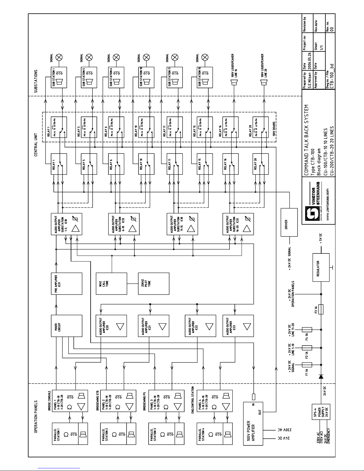


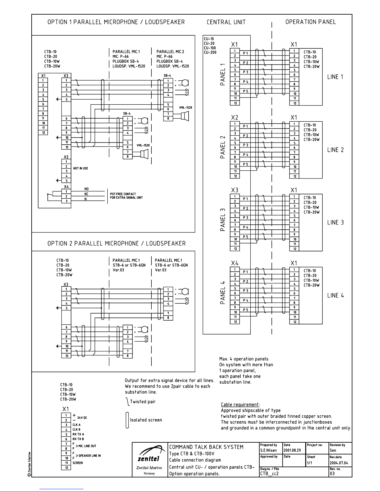

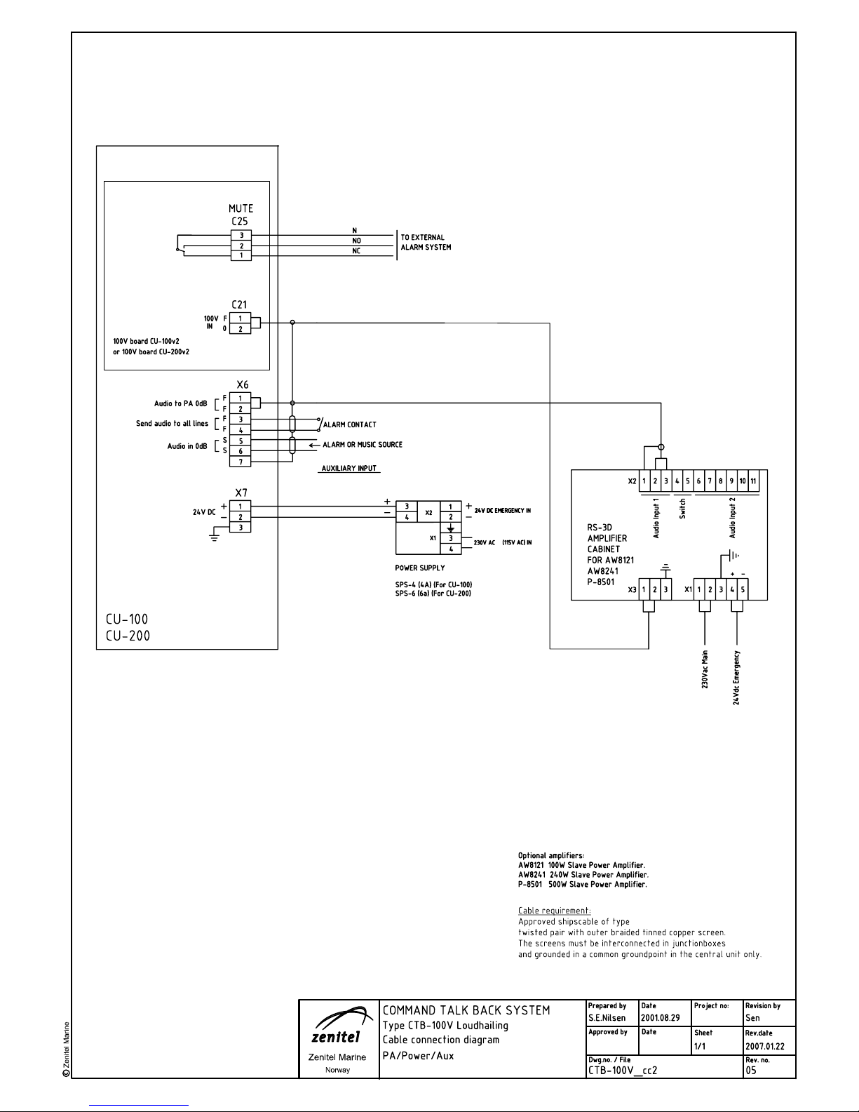
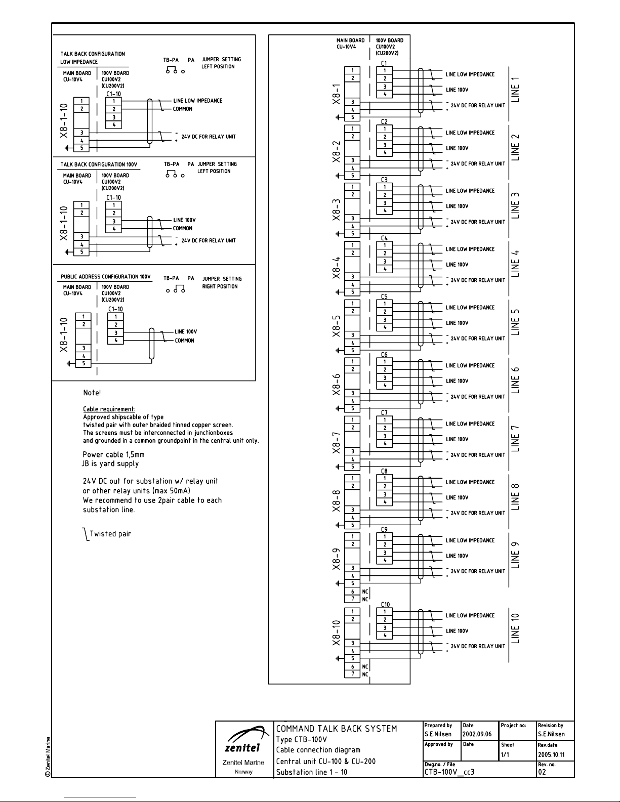


Features
Document no.
Article no.
CU-100_ds rev.02 2004.09.06
CU-100
Technical data:
CU-100
T alk-Back Systems
Description:
400
4
0
0
M
o
u
n
t
i
n
g
h
o
l
e
s
d
i
s
t
a
n
c
e
=
3
8
0
m
m
Mounting holes distance = 380 mm
hole diameter = Ø 6 mm
120
Gap for cable inlet
100x60 left and right side
CU-100
* Central unit 10 lines for CTB-100V system
* Operates with CTB-10 panel unit
* AUX / Alarm input
* Signal oscillator
* 24 VDC power supply
* 100 V line output
* High power amplification by use of external 100V line
power amplifier
Material / finish: Aluminium / black.
Mounting: Bulkhead with 4 x 4mm
screws
Terminals: Plugable screw terminals
for cable max. 2,5mm
2
Fuses: F1,F2,F3;F4 1A 5 x 20
DIP-switches: For P A-zones, set priority,
set receive call.
Pot.meter: For volume setting line
1-5, 6-10
Dimension W/H/D mm: 400 x 400 x 120
Weight: Approx. 3,2Kg
Protection: IP-22
External connections: 4x Operation panels, up to
10 substations, AUX, PA
AUX input: 0 dB 0,775V / 600ohm
Alarm contact: Potential free N/O
Frequency range: 200Hz - 8KHz (-3dB)
Temperature operating: -20 + 55
0
C
Humidity: 5 - 95 %
Power supply: 20 - 32V DC
Power consumption
at 24V DC: 2,5 A
Output power: Depending on external
100V power amplifier
Output impedance: 100V per line
www.zenitel.biz\Communication & Security Systems\Zenitel Marine

Features
Document no.
Article no.
CU-200_ds rev.02 2004.09.06
CU-200
Technical data:
CU-200
T alk-Back Systems
Description:
400
4
0
0
M
o
u
n
t
i
n
g
h
o
l
e
s
d
i
s
t
a
n
c
e
=
3
8
0
m
m
Mounting holes distance = 380 mm
hole diameter = Ø 6 mm
120
Gap for cable inlet
100x60 left and right side
CU-200
* Central unit 20 lines for CTB-100V system
* Operates with CTB-20 panel unit
* AUX / Alarm input
* Signal oscillator
* 24 VDC power supply
* 100 V line output
* High power amplification by use of external power
amplifier
Material / finish: Aluminium / black.
Mounting: Bulkhead with 4 x 4mm
screws
Terminals: Plugable screw terminals
for cable max. 2,5mm
2
Fuses: F1,F2,F3;F4 1A 5 x 20
DIP-switches: For PA-zones, set priority, set
receive call.
Pot.meter: For volume setting line
1-5, 6-10, 11-15, 16-20
Dimension W/H/D mm: 400 x 400 x 120
Weight: Approx. 3,2Kg
Protection: IP-22
External connections: 4x Operation panels, up to
20 substations, AUX, PA
AUX input: 0 dB 0,775V / 600ohm
Alarm contact: Potential free N/O
Frequency range: 200Hz - 8KHz (-3dB)
Temperature operating: -20 + 55
0
C
Humidity: 5 - 95 %
Power supply: 20 - 32V DC
Power consumption
at 24V DC: 5 A
Output power: Depending on external
100V power amplifier
Output impedance: 100V per line
www.zenitel.biz\Communication & Security Systems\Zenitel Marine

Features
Document no.
Article no.
CTB-10_ds rev.03 2005.01.06
CTB-10
Technical data:
CTB-10
T alk-Back Systems
Description:
230
1
3
4
240
1
4
4
Mounting holes = Ø 4,5 mm
Panel cut-out = 224 x 132
3
_
+
VOLUME
TALK
_
+
12345
6789
ALL
BAUX
10
DIM SIGN
CTB-10
* Operator panel CTB-10 with 10 lines selection
* Operates with CU-10 or CU-20 central unit
* Bridge Wing communciation facility
* All Call / Group Call facility
* Re-entrant monitor-speaker / microphone
* Connector for gooseneck or handheld microphone
* Dimable panel background light
* Extension buttons with memory light
* Buzzer indication of incoming calls
* Step volume control
* Signal oscillator
* Output for extra signal device all lines
Material / finish: Aluminium / black.
Mounting: Flush with 4 x 4mm screws
Optional Back box for bulkhead
mounting.
Terminals: Plugable screw terminals
for cable max. 2,5mm
2
Cable gland: 2x PG-16
Dimension W/H/D mm: 240 x 144 x 100
Cut out dimension: 224 x 132
Weight: Approx. 1,2Kg
Microphone input: Contact for handheld and
electret gooseneck microphone
External connections: Central unit, ext. microphones.
ext.loudspeaker
Front panel: Graphic front film
Switches: Push button type with LED
indication
Loudspeaker: 3W / 8 ohm
IP rating: IP-47
PG16
100
1
2
5
30
www.zenitel.biz\Communication & Security Systems\Zenitel Marine

Features
Document no.
Article no.
CTB-20_ds rev.03 2005.01.06
CTB-20
Technical data:
CTB-20
T alk-Back Systems
Description:
230
1
3
4
240
1
4
4
3
_
+
VOLUME
TALK
_
_
+
12345
6789
11
ALL
BAUX
16
12 13 14 15
17 18 19 20
10
DIM SIGN
CTB-20
* Operator panel CTB-20 with 20 lines selection
* Operates with CU-20 central unit
* Bridge Wing communication facility
* All Call / Group Call facility
* Re-entrant monitor-speaker / microphone
* Connector for gooseneck or handheld microphone
* Dimable panel background light
* Extension buttons with memory light
* Buzzer indication of incoming calls
* Step volume control
* Signal oscillator
* Output for extra signal device all lines
Material / finish: Aluminium / black.
Mounting: Flush with 4 x 4mm screws
Optional Back box for
bulkhead mounting.
Terminals: Plugable screw terminals
for cable max. 2,5mm
2
Cable gland: 2x PG-16
Dimension W/H/D mm: 240 x 144 x 100
Cut out dimension: 224 x 132
Weight: Approx. 1,2Kg
Microphone input: Contact for handheld and
elec. gooseneck microphone
External connections: Central unit, ext. microphones.
ext.loudspeaker
Front panel: Graphic front film
Switches: Push button type with LED
indication
Loudspeaker: 3W / 8 ohm
IP rating: IP-47
PG16
100
1
2
5
30
www.zenitel.biz\Communication & Security Systems\Zenitel Marine
Mounting holes = Ø 4,5 mm
Panel cut-out = 224 x 132

Features
Document no.
Article no.
CTB-10W / V01_ds rev.00 2005.01.03
CTB-10W / V01
Technical data:
CTB-10 W / V01
T alk-Back Systems
Description:
CTB-10W / V01
* Operator panel with 10 lines selection,
and loudspeaker HP-8, bulkhead mounting.
* Option, microphone P-66 and P-66/10
* Operates with CU-10 or CU-100 central unit
* Bridge Wing communication facilty
* All Call / Group Call facility
* Re-entrant monitor-speaker/microphone
* Dimable memory light
* Line buttons with memory light
* Buzzer indication of incoming calls
* Step volume control
* Signal oscillator
* Weather-proof
Material / finish: Aluminium / Steinless steel
Box ABS plastic.
Mounting: Bulkhead mounting
with 4 x 4mm screws
Terminals: Plugable screw terminals for
cable max. 2,5mm
2
Dimension W/H/D mm: 300 x 160 x 156
Weight: Approx. 1,4Kg
External connections: Central unit, ext. loudspeakers
Front panel: Graphic front film
Switches: Push button type with LED
indication
Microphone contact: Amphenol w/cover IP-67
WP Microphone: P-66 or P-66/10,
see seperate datasheet.
Loudspeaker: External loudspeaker
HP-8 8ohm
See seperate datasheet.
Protection: IP-66
www.zenitel.biz\Communication & Security Systems\Zenitel Marine
Technical data:

Features
Document no.
Article no.
CTB-20W / V01_ds rev.00 2005.01.03
CTB-20W / V01
Technical data:
CTB-20W / V01
T alk-Back Systems
Description:
Material / finish: Aluminium / Steinless steel
Box ABS plastic.
Mounting: Bulkhead mounting
with 4 x 4mm screws
Terminals: Plugable screw terminals for
cable max. 2,5mm
2
Dimension W/H/D mm: 300 x 160 x 156
Weight: Approx. 1,4Kg
External connections: Central unit, ext. loudspeakers
Front panel: Graphic front film
Switches: Push button type with LED
indication
Microphone contact: Amphenol w/cover IP-67
WP Microphone: P-66 or P-66/10,
see seperate datasheet.
Loudspeaker: External loudspeaker
HP-8 8ohm
See seperate datasheet.
Protection: IP-66
www.zenitel.biz\Communication & Security Systems\Zenitel Marine
Technical data:
CTB-20W / V01
* Operator panel with 20 lines selection,
and loudspeaker HP-8, bulkhead mounting.
* Option, microphone P-66 and P-66/10
* Operates with CU-20 or CU-200 central unit
* Bridge Wing communication facilty
* All Call / Group Call facility
* Re-entrant monitor-speaker/microphone
* Dimable memory light
* Line buttons with memory light
* Buzzer indication of incoming calls
* Step volume control
* Signal oscillator
* Weather-proof

Features
Document no.
Article no.
VMT-603_ ds. rev.02 2004.09.02
VMT-603
Technical data:
VMT-603
ACM System - Stations
Description:
80
50
220
120
PG21
PG7
VMT-603
Mounting holes diam. 6.0 mm
204
82
VMT-603:
* W/t PA station for interuption of Alarm signals for
Emergency messages
* For wall mounting at muster or embarkment stations
Handheld mic.: 62A0005
Connection: Internal screw terminals
Housing: ROSE Box
Colour: Grey box / Black sign
IP rating: IP-65
Dimensions: See dwg. beside
Weight: 1,4 kg
www.zenitel.biz\Communication & Security Systems\Zenitel Marine

Features
Document no.
Article no.
HP-8_ds rev.00 2005.03.15
HP-8
Technical data:
HP-8
Loudspeakers
Description:
HP-8
Horn loudspeaker for use on open deck areas, eng room etc.
WP , IP-67.
Manufacturer: DNH A/S
Material / Colour: Polyamide / RAL 7035
Mounting: Bracket or flush
Termination: 0,5m cable
Weight: 0,75 kg
IP-rating (UL Equivalent) IP-67
Max. / min. amb. temp: 150 °C / -50 °C
Impedance: 8 ohm
Rated / max. power: 8 W / 15 W
SPL 1 W / 1 m: 101 dB
SPL rated power: 110 dB
Effective freq. range: 600 - 7500 Hz
Dispersion (-6 dB)1kHz / 4kHz: 160° / 50°
Directivity factor, Q : 6,0
HP-8T:
Transformer 100V
Primary nominal tappings:
1 : 2 8,0W
2 : 3 4,0W
3 : 4 2,0W
1 : 3 1,5W
2 : 4 0,7W
1 : 4 0,4W
1= Red, 2= Yellow, 3= Green, 4= Blue
www.zenitel.biz\Communication & Security Systems\Zenitel Marine
Features
Document no.
Article no.
MB-30G_ds rev.02 2004.08.30
MB-30G
Technical data:
MB-30G
Common Equipment
Description:
460
36
MB-30G
* Gooseneck microphone
* For use in: Public Address System and Talk-Back System
Manufacturer: Paso
Type : Electret
Art.no. : MB30G
Impedance: 2 K ohm
Freq.response: 100 - 20000Hz.
Sensitivity: 4mv/Pa.
Supply: 1,1-9V.
Front rear ratio: 10 dB
Length: 430mm
Plug: 5 pole din
Accessories: Sponge windscreen
Dimensions: See dwg. beside
Weight: 0,1 kg
www.zenitel.biz\Communication & Security Systems\Zenitel Marine

Features
Document no.
Article no.
ETC-1-TB_ds rev.03 2004.10.15
ETC-1-TB
Technical data:
ETC-1-TB
T alk-Back Systems
Description:
5847
102
ETC-1-TB
* Handheld microphone for use with ETB and CTB control
unit panels.
Type : Dynamic
Art.no. : ETC-1-TB
Impedance: 200 ohm
Freq.response: 200 - 4500Hz.
Sensitivity: 1 mV/Pa.
Polar pattern: Non directional
Switch: PTT
Cable: 3-wires coiled cord w/ shield
Plug: 5 pole din
Accessories: Hang-up clip
Dimensions: See dwg. beside
Weight: 0,2 kg
45
36
24
Ø 3 mm
Mic. clip-on
www.zenitel.biz\Communication & Security Systems\Zenitel Marine

Features
P-66Common Equipment
Description:
T echnical dat a:
Ø54
54
72
81
29
P-66
* Watertight, salt water resistant handheld microphone-
loudspeaker unit.
* Suitable for heavy-duty outdoor operation subject to
noise disturbance.
* Delivered with 2 meter flexicable and plug.
* For use in: Public Address System and Talk-Back
System.
Manufacturer: Holmberg & Co
Type/art.no.: Holmco 66 / 84-15-06980
DC resistance: 200 ohm
Mic.sensitivity: 0.5 mV/dyne/sq.cm
at 1 kHz
Power capacity: 0.2 W (0.5 W peak)
LS sensitivity: 57 dB/mW at 1 kHz
and 50 cm distance
i.e. 80 dB at 0.2 W audio-
frequency power.
Working temp. -30 to +60 °C
IP class: IP-66
Colour: Black
Dimensions: see dwg. beside
Weight: 0,3 kg
P-66_ds rev.03 2004.08.30
P-66
Document no.
Article no.
www.zenitel.biz\Communication & Security Systems\Zenitel Marine

Features
P-66-10Common Equipment
Description:
T echnical dat a:
P-66/10
* Watertight, salt water resistant handheld microphone-
loudspeaker unit.
* Suitable for heavy-duty outdoor operation subject to
noise disturbance.
* Delivered with 10 meter cord and plug.
* For use in: Public Address System and Talk-Back System
Manufacturer: Holmberg & Co
Type/art.no.: Holmco 66 / 84-15-
06980
DC resistance: 200 ohm
Mic.sensitivity: 0.5 mV/dyne/sq.cm
at 1 kHz
Power capacity: 0.2 W (0.5 W peak)
LS sensitivity: 57 dB/mW at 1 kHz
and 50 cm distance
i.e. 80 dB at 0.2 W
audio-frequency power.
Working temp. -30 to +60 °C
IP class: IP-66
Colour: Black
Dimensions: see dwg. above
Weight: 0,4 kg
P-66-10_ds rev.03 2004.08.30
P-66-10
Document no.
Article no.
10 m cable
Ø54
8
1
7
2
29
10 m cable
54
www.zenitel.biz\Communication & Security Systems\Zenitel Marine

Features
Document no.
Article no.
AW8121_ds rev.01 2004.08.30
AW8121
Technical data:
AW8121
Public Address Systems
Description:
OUTPUT LEVEL OVERL. ON
BASS TREBLE MASTER VOLUME POWER
0 0 5
10 +10 10 +10 0 10
dB +40 -6 0 +1
SERIES POWER AMPLIFIER
FUSE ~
V ~
IN A.P.T. LEVEL
(260W) 24V COM. 8Ω
LEVEL IN OUT
LEVEL TONE
16Ω 50V 7 0V 100 V
REMOTE ALARM
1 2 3
CHIME
BASE BOOSTER
...
CAUTION: CA UTION:
TO REDUCE DISCONNECT POWER
THE RISK SU PPLY CORD
OF FIRE BEFORE CHANGING
REPLACE FUSE .
ONLY WITH
SAME TYPE
FUSE.
POWER AM PL IFIER AW8121
MAINS FUSE ~ RATING CONSUMPT.
230V ~ T 2.5 A 120W RMS 450 W
MADE IN ITA LY
482,6
132
AW8121
* 19” 3 HU 120 W power amplifier
* 230 Vac / 24 Vdc power supply
Manufacturer: Paso
Colour: Black
Power AC: 120 W
Constant voltage outputs: 100, 70, 50 V
Constant impedance
outputs: 16, 8 ohm
Distortion at rated power: < 1 %
Tones control: Bass ( 100 Hz ) +/- 10 dB
Trebe ( 10kHz ) +/- 10 dB
Booster input:
Sensitivity / impedance: <1,1 V / 100 Kohm
S/N ratio: 80 dB
Frequency response: 40 - 20 000 Hz
Precedence attenuation: 55 dB
Amplified stand input:
Sensitivity / impedance: 220 mV / 10 Kohm
S/N ratio: 80 dB
Frequency response: 150 - 14 000 Hz
Weight: Approx. 14 kg
Debth: 340
Debth w/ carrying handle: 380
www.zenitel.biz\Communication & Security Systems\Zenitel Marine

Features
Document no.
Article no.
AW8241_ds rev.02 2004.08.30
AW8241
Technical data:
AW8241
Public Address Systems
Description:
OUTPUT LEVEL OVERL. ON
BASS TREBLE MASTER VOLUME POWER
0 0 5
10 +10 10 +10 0 10
dB +40 -6 0 +1
SERIES POWER AMPLIFIER
FUSE ~
V ~
IN A.P.T. LEVEL
230V ~ T 2.5 A 240W RMS 450 W
MADE IN ITA LY
(260W) 24V COM. 8
Ω
LEVEL IN OUT
LEVEL TONE
16Ω 50V 70V 100 V
REMOTE ALARM
1 2 3
CHIME
BASE BOOSTER
...
CAUTION: CA UTION:
TO REDUCE DISCONNECT POWER
THE RISK SU PPLY CORD
OF FIRE BEFORE CHANGING
REPLACE FUSE .
ONLY WITH
SAME TYPE
FUSE.
POWER AM PL IFIER AW8241
MAINS FUSE ~ RATING CONSUMPT.
482,6
132
AW8241
* 19” 3 HU 240 W power amplifier
* 230 Vac / 24 Vdc power supply
Manufacturer: Paso
Colour: Black
Power AC: 240 W
Constant voltage outputs: 100, 70, 50 V
Constant impedance
outputs: 16, 8 ohm
Distortion at rated power: < 1 %
Tones control: Bass ( 100 Hz ) +/- 10 dB
Treble ( 10kHz ) +/- 10 dB
Booster input:
Sensitivity / impedance: <1,1 V / 100 Kohm
S/N ratio: 80 dB
Frequency response: 40 - 20 000 Hz
Precedence attenuation: 55 dB
Amplified stand input:
Sensitivity / impedance: 220 mV / 10 Kohm
S/N ratio: 80 dB
Frequency response: 150 - 14 000 Hz
Weight: Approx. 17 kg
Debth: 340
Debth w/ carrying handle: 380
www.zenitel.biz\Communication & Security Systems\Zenitel Marine

Features
P8501Public Address Systems
Description:
T echnical dat a:
P8501_ds rev.03 2004.08.30
P8501
Document no.
Article no.
OUTPUT LEVEL OVERL. POWER
ON
dB
-40 -12 -6 0 +1
OFF
SERIES POWER AMPLIFIER
BASS TREBLE VOLUME
0 0 5
10- +10 10- +10 0 10
V ~
FUSE ~
24V
...
- +
CONSUMPT. 800W
FUSE
32A
SQUELCH
RF
VOLUME
f ( MHz )
5
0
10
ANTENNA
REMOTE ALARM
1 2 3
POWER AMPLIFI ER
P 8501
0 1,25Ω 5Ω 9,4Ω 20Ω
0 25V 50V 70V 100V
CAUTION: DO NOT OBSTR UCT OPENING!
MAINS FUSE ~ RATING CONSUMPT.
230V ~ T 6.3 A 500W RMS 950W
MADE IN ITALY
LEVEL TONE
INPUT
A.P.T.
LEVEL O UTPUT
INPUT LEVEL
CHIME BASE BOOS TER
CAUTION: CAUTION:
TO REDUCE DISCONNECT POWER
THE RISK SUPPLY CORD
OF FIRE BEFORE CHANGING
REPLACE FUSE.
ONLY WITH
SAME TYPE
FUSE.
482,6
132
P-8501
* 19” 3 HU 500 W power amplifier
* 230 Vac / 24 Vdc power supply
Manufacturer: Paso
Colour: Black
Dimensions: 482 x 133 x 420 mm
Power AC: 500 W
Constant voltage outputs: 100, 70, 50, 25 V
Constant impedance outputs: 20, 9.4, 5, 1.25 ohm
Distortion at rated power: < 0,5 %
Tones control: Bass ( 100 Hz ) +/- 10 dB
Treble ( 10kHz ) +/- 10 dB
Booster input:
Sensitivity / impedance: 220 mV / 10 Kohm
S/N ratio: > 80 dB
Frequency response: 50 - 20 000 Hz (0/-3 dB)
Precedence attenuation: > 40 dB
Amplified stand input:
Sensitivity / impedance: 400 mV / 10 Kohm
S/N ratio: > 80 dB
Frequency response: 180 - 20 000 Hz ( 0/-3 dB )
Max. current absorption: 200 mA
Power consumption (mains): 950 W / 1150 VA
External DC power supply: 24 V
Current consumption (dc power): Max. 25 A
Operating/ storage temp. range: -10 °C to +45 °C /
-40 °C to +70 °C
Relative humidity: < 95 %
Weight: 25 kg
www.zenitel.biz\Communication & Security Systems\Zenitel Marine

Features
Document no.
Article no.
RS-3D_ds rev.00 2004.08.22
RS-3D
Integrated Communication System RS-3D
Description:
Technical data:
RS-3D
3 HU 19” cabinet, prepared for amplifier
AW8121, AW8241 and P-8501
with all necessary terminals for external 230 Vac /
24 Vdc in and out signals
Dimensions (WxHxD): 520 x 450 x 180
Mounting: 6x 5mm screws
Weight: Approx.6Kg.
Housing: Aluminium elox.
Colour: Black
Cable entry: Rear side
Connections: Screwterminals
Operation voltage: 24VDC or 230VAC
Options: Poweramplifers AW8121, AW8241 and P-8501
See separate datasheet.
TOP VIEW
450
180
125
50
100
100
250
570
1
0
0
1
0
0
FRONT VIEW
REAR VIEW
SIDE VIEW
MOUNTING HOLES Ø 5,2MM
www.zenitel.biz\Communication & Security Systems\Zenitel Marine
X2
X1
K1
1 2 3 4 5
1 2 3 4 5 6 7 8 9 10 11
1 2 3
X3
520
FRONT VIEW
520
OUTPUT LEVEL OVERL. ON
BASS TREBLE M ASTER VOLUME POWER
0 0 5
10 +10 10 +10 0 10
dB +40 -6 0 +1
SERIES POWER AMPLIFIER

Features
Document no.
Article no.
STB-1
Technical data:
STB-1
T alk-Back Systems
Description:
STB-1
* Talk-Back substation, designed for use in cabins,
messrooms, etc.
* Delivered for bulkhead mounting
* Call-button for calling Master unit
* Privacy
* Talk-button with privacy off function.
Connections: Screw terminals
Colour: Black front
IP rating IP-44
Dimensions: See dwg. beside
Weight: 0,35 kg
STB-1_ ds. rev.04 2004.10.12
96
96
ø4
Ø18
Cable inlet
73
48
144
72
47
144
4996
144
www.zenitel.biz\Communication & Security Systems\Zenitel Marine

Features
SPEAKER
SS LINE
A
B
SCREW TERMINAL
1
2
3
4
EXTERNAL
Document no.
Article no.
80 28
2 x PG13
,
5
CALL
63
110
94
46
Mounting hole
diam. 4.5 mm
STB-2
T alk-Back Systems
Technical data:
Description:
STB-2
* Calling box
* Delivered for bulkhead mounting
* Call-button for calling Master unit
* Forming a loudspeaking Talk-Back Substation
together with a horn loudspeaker.
Connections: Screw terminals
Colour: Grey
IP rating IP-66
Dimensions: See dwg. beside
Weight: 0,3 kg
STB-2_ ds. rev.03 2004.10.12
STB-2
www.zenitel.biz\Communication & Security Systems\Zenitel Marine

Features
Document no.
Article no.
STB-3_ ds. rev.03 2004.10.13
STB-3
Technical data:
STB-3
T alk-Back Systems
Description:
80
28
63
224
208
46
Mountin g hole
diam. 4.5 mm
38
4 x PG13,5
HEADSET
ON
CALL
CALL
EXTERNAL
SPEAKER
SS LINE
A
B
0V
+24V
0V
+24V
0V
+24V
SIGNAL DEVICE IN
EXTRA SIGNAL DEVICE
IN
OUT
SCREW TERMINAL
9
10
1
2
3
4
5
6
7
8
STB-3
* Calling unit
* Delivered for bulkhead mounting
* Call-button for calling Master unit
* Call-button with LED for incoming call indication
* Socket with dust-cap for connection of headset or
microphone
* Built-in relay circuit for operation of external signalling
devices.
* Forming a loudspeaking Talk-Back substation
together with a horn loudspeaker.
Connections: Screw terminals
Colour: Grey
IP rating IP-66
Dimensions: See dwg. beside
Weight: 0,5 kg
www.zenitel.biz\Communication & Security Systems\Zenitel Marine

Features
Document no.
Article no.
P-MT7_ds rev.03 2004.09.01
P-MT7
Analogue Telephone System P-MT7
Description:
Technical data:
P-MT7
* Headset for Analogue Telephone System connected
through HSB-01 or HSB-0.2
* Standard with 10 meter cable and plug.
* To be used in noisy areas.
* Includes headset holder.
Connections: 4 pin Amphenol ( C16-1 )
Headset: Peltor MT 7H7A
Colour: Black
IP rating: IP-54
Dimensions: See dwg. beside
Weight: Approx. 1,2 kg
10m cable
200
95
40
40
60
124
Headset holder
10m cable
110
www.zenitel.biz\Communication & Security Systems\Zenitel Marine

Features
Document no.
Article no.
STB-5_ds rev.02 2004.09.07
STB-5
Description:
Technical data:
STB-5
T alk-Back Systems
CALL
3
PG16
144
144
57
Panel cut-out = 125 x 125 mm
Mounting holes = Ø 4 mm
134
134
120
30
SS LINE
A
B
0V
+24V
0V
+24V
0V
+24V
SIGNAL DEVICE IN
EXTR A S I GNAL DEVICE
IN
OUT
SCREW TERMINAL
1
2
3
4
5
6
7
8
STB-5
* Talk-Back substation, designed for multipurpose indoor
use ( engine room )
* Delivered for flush or bulkhead mounting
* Call button for calling Master unit
* Built-in relay circuit for operating of external signalling
devices.
* Loudspeaker
* Socket for handset or handheld microphone
Material / Colour: Aluminium / black
Connections: Screw Terminals
Loudspeaker: 3 W
Dimensions: See dwg. above
Weight: Approx. 0,5 kg
IP rating: IP-44
Accessories:
Box for bulkhead mounting ( see seperate datasheet )
Handset HAS-1 ( see seperate datasheet )
Handheld microphone ETC-STB5 ( see seperate
datasheet )
www.zenitel.biz\Communication & Security Systems\Zenitel Marine

Features
CALL
3
144
134
144
134
Mounting holes Ø 4 mm
SIGN
Document no.
Article no.
STB-5GN_ds rev.03 2004.10.13
STB-5GN
Description:
Technical data:
STB-5GN
T alk-Back Systems
SS LINE
A
B
0V
+24V
0V
+24V
0V
+24V
SIGNAL DEVICE IN
EXTRA SIGNAL DEVICE
IN
OUT
SCREW TERMINAL
1
2
3
4
5
6
7
8
STB-5GN
· Talk-Back substation, designed for multipurpose indoor
use ( engine room )
· Delivered for flush or bulkhead mounting
· Call button for calling Master unit
· Built-in relay circuit for operating of external signalling
devices.
· Loudspeaker
· Gooseneck microphone
Accessories:
Box for bulkhead mounting ( see seperate datasheet )
Material / Colour: Aluminium / black
Connections: Screw Terminals
Loudspeaker: 3 W
Dimensions: See dwg. above
Weight: Approx. 0,9 kg
IP rating: IP-44
Gooseneck microphone M610:
Colour: Black
Length: 330 mm
Type: Uni-directional cardioid
microphone ( dynamic )
Freq. response: 50 - 16 000 Hz
Sensitivity: 1,5 mV
PG16
120
57 30
www.zenitel.biz\Communication & Security Systems\Zenitel Marine

Features
Document no.
Article no.
HAS-1_ds rev.03 2004.09.07
HAS-1
Technical data:
HAS-1
T alk-Back Systems
Description:
HAS-1
* Handset with cradle designed for use together with
Talk-back substation STB-5
Colour: Black
Material: Metal ( cradle ) /
plastic ( handset )
Spiralcord: Approx. 1,2 m
Plug: 5 pin DIN
Switch: ON / OFF
Weight: 0,55 kg
220
30
60
55
Mounting holes
Ø 3,5 mm
80
43
www.zenitel.biz\Communication & Security Systems\Zenitel Marine

Features
Document no.
Article no.
ETC-STB5_ds rev.03 2004.10.19
ETC-STB5
Technical data:
ETC-STB5
T alk-Back Systems
Description:
5847
102
ETC-STB5
* Handheld microphone configurated for substation STB-5
Type : Dynamic
Art.no. : ETC-STB5
Impedance: 200 ohm
Freq.response: 200 - 4500Hz.
Sensitivity: 1 mV/Pa.
Polar pattern: Non directional
Switch: PTT
Cable: 3-wires coiled cord w/ shield
Plug: 5 pole din
Accessories: Hang-up clip
Weight: 0,2 kg
45
36
24
Ø 3 mm
Mic. clip-on
www.zenitel.biz\Communication & Security Systems\Zenitel Marine

Features
Document no.
Article no.
VH-10M_ds rev.03 2004.10.15
VH-10M
Description:
Technical data:
VH-10M
T alk-Back System
VH-10M
* Portable deck loudspeaker with callbox
* Delivered with 10 meter cable and plug
Material: Anodized aluminium ( Backplate ) /
ABS ( Speaker )
Colour: Black ( Backplate ) / Grey ( Speaker )
Dimensions: See dwg. above
IP rating: IP-65
Weight: 3,7 kg
For further data:
Speaker VML-1508, see separate datasheet
Accessories:
Plugbox CD-2 ( See separate datasheet )
www.zenitel.biz\Communication & Security Systems\Zenitel Marine
10m cable
156
250
145
6
4
CALL
10m cable
305
410
153
407
For fixed mounting
M
ounting holes Ø 4

Features
Document no.
Article no.
VH-10M-T_ds rev.00 2004.10.21
VH-10M
Description:
Technical data:
VH-10M-T
T alk-Back System
VH-10M-T
* Portable deck loudspeaker 100V with callbox
* Delivered with 10 meter cable and plug
Material: Anodized aluminium ( Backplate ) /
ABS ( Speaker )
Colour: Black ( Backplate ) / Grey ( Speaker )
Dimensions: See dwg. above
IP rating: IP-65
Weight: 3,7 kg
For further data:
Speaker VML-15T, see separate datasheet
Accessories:
Plugbox CD-2 ( See separate datasheet )
www.zenitel.biz\Communication & Security Systems\Zenitel Marine
10m cable
156
250
145
6
4
CALL
10m cable
305
410
153
407
For fixed mounting
M
ounting holes Ø 4

Features
1
2
3
Pair 1
Pair
2
A
B
C
Socket
no.
Terminal
strip
63
27
110
94
46
Mounting ho l e
diam. 4.5 mm
Document no.
Article no.
CD-2_ds rev.02 2004.09.07
CD-2
Technical data:
CD-2
T alk-Back Systems
Description:
Connections: Screw terminals
Colour: Grey
IP rating: IP-66
Dimensions: See dwg. above
Weight: 0,35 kg
CD-2
* Watertight plug box
* Designed to be used together with substations, VH-10M
and VH-10MT
* Socket with dustcap
* Delivered for bulkhead mounting
* Suitable for installation in noisy areas
80 24
PG11
www.zenitel.biz\Communication & Security Systems\Zenitel Marine

Features
152
239
247
334
275
75
CALL
Document no.
Article no.
VHM-10_ds rev.03 2004.10.15
VHM-10
Description:
Technical data:
VHM-10
T alk-Back System
215
160
15
310
MOUNTING HOLES Ø 8,5
VHM-10
* Special substation with hand microphone and callbox in a
cabinet
Material: Polycarbonate ( Cabinet )
Colour: Grey ( Cabinet )
Dimensions: See dwg. above
IP rating: IP-66
Weight: 2,5 kg
Microphone P-66:
Colour: Black
IP class: IP-66
DC resistance: 200 ohm
Mic.sensitivity: 0.5 mV/dyne/sq.cm at 1 kHz
Power capacity: 0.2 W (0.5 W peak)
LS sensitivity: 57 dB/mW at 1 kHz and 50 cm
distance i.e. 80 dB at 0.2 W
audio-frequency power.
Dimensions: Ø 54 x 8 1 x 5 4
Working temp. -30 to +60 °C
Weight: 0,3 kg
www.zenitel.biz\Communication & Security Systems\Zenitel Marine

Features
152
239
247
334
275
75
CALL
Document no.
Article no.
VHM-10-T_ds rev.00 2004.10.21
VHM-10-T
Description:
Technical data:
VHM-10T
T alk-Back System
215
160
15
310
MOUNTING HOLES Ø 8,5
VHM-10T
* Special substation with hand microphone and callbox in a
cabinet. For connection to 100V loudspeaker
Material: Polycarbonate ( Cabinet )
Colour: Grey ( Cabinet )
Dimensions: See dwg. above
IP rating: IP-66
Weight: 2,5 kg
Microphone P-66:
Colour: Black
IP class: IP-66
DC resistance: 200 ohm
Mic.sensitivity: 0.5 mV/dyne/sq.cm at 1 kHz
Power capacity: 0.2 W (0.5 W peak)
LS sensitivity: 57 dB/mW at 1 kHz and 50 cm
distance i.e. 80 dB at 0.2 W
audio-frequency power.
Dimensions: Ø 54 x 8 1 x 5 4
Working temp. -30 to +60 °C
Weight: 0,3 kg
www.zenitel.biz\Communication & Security Systems\Zenitel Marine

Features
Document no.
Article no.
HE-112M_ds rev.04 2006.05.11
HE-112M
Technical data:
HE-112M
Talk-Back Systems
Description:
CALL
122
90
120
10
20
30
PG16
90
110
Mounting holes
4 mm
terminal strip
B
A
Connection to central unit
HE-112M
* Talk-Back Substation, designed for use in open deck
areas
* Delivered for bulkhead mounting
* Call-button for calling Master unit
Connections: Screw terminals
Colour: Grey
IP rating: IP-66
Dimensions: See dwg. beside
Weight: 0,4 kg
www.zenitel.biz\Communication & Security Systems\Zenitel Marine

Features
Document no.
Article no.
HE-112MT_ds rev.04 2006.05.11
HE-112MT
Technical data:
HE-112MT
Talk-Back Systems
Description:
HE-112MT
* Talk-Back Substation, designed for use in open deck areas
* To be used with 100 volt line amplifiers
* Delivered for bulkhead mounting
* Call-button for calling Master unit
Connections: Screw terminals
Transformer: For 100V line ampl.
Colour: Grey
IP rating: IP-66
Dimensions: See dwg. beside
Weight: 0,6 kg
terminal strip
B
A
Connection to central unit
90
110
Mounting holes
4 mm
CALL
122
90
120
10
20
30
PG16
www.zenitel.biz\Communication & Security Systems\Zenitel Marine
 Loading...