

Vincent Associates VCM-D1 User Manual

1.800.828.6972
User Manual
VCM-D1 Shutter Driver
14-0025
Version 3.20
2013
VCM-D1 User Manual

For information regarding applicable intellectual property, please visit
www.uniblitz.com/patents.
Information in this publication supersedes that in all previously published material. Due to
our ongoing development program, Vincent Associates reserves the right to discontinue or
change specifications or designs, at any time, without incurring any obligation.
Version 3.20
2013
Vincent Associates, a Division of VA, Inc., 803 Linden Ave., Rochester, NY 14625
Tel: 585-385-5930 Fax: 585-385-6004
UNIBLITZ is a registered trademark of VA, Inc.
Printed in the U.S.A.
VCM-D1 User Manual 1

2
WARRANTY
LIMITED PRODUCT WARRANTY: All Products manufactured by VINCENT
ASSOCIATES® (MANUFACTURER) are warranted to meet published specifications and
to be free of defects in materials and workmanship as defined in the specifications for 365
days - one year - (WARRANTY PERIOD) from the date of original shipment of the
product. DSS series shutters are additionally warranted to achieve two million cycles within
the WARRANTY PERIOD (as defined in the CYCLE WARRANTY CRITERION).
MANUFACTURER will, at its own option within the WARRANTY PERIOD, repair or
replace without charge any listed item discovered to be defective excepting transportation
charges. Burned out or otherwise damaged actuator coils are not covered under this
warranty. Any defective product returned to the MANUFACTURER must follow the
RETURN MATERIAL AUTHORIZATION PROCEDURE as defined below. This warranty
does not extend to cover damage resulting from alteration, misuse, negligence, abuse,
normal wear and tear, or accident. The MANUFACTURER will consider the return of
unused equipment if returned within 30 days from the original date of shipment, subject to a
20% restocking charge. This offer does not apply to used or damaged equipment. This
warranty extends only to the original purchase and is not available to any third party,
including any purchaser assemblies or other Products of which the goods may become
component equipment.
CYCLE WARRANTY CRITERION: One "cycle" is considered one open and one closure
of the shutter. DSS Shutter must be operated with the ED12DSS driver or equivalent HBridge type shutter driver circuit at +10.7VDC across the actuator coil for the specified
duration. DSS Shutter must be operated within the defined environmental, electrical and
mechanical specifications as listed on the device's data sheet. After one year (WARRANTY
PERIOD), the cycle warranty is null and void. If returned, the device must be accompanied
by a written statement indicating the approximate number of cycles contained on the device,
include all parameters to which the shutter was operated and follow the RETURN
MATERIAL AUTHORIZATION PROCEDURE as defined below.
RETURN MATERIAL AUTHORIZATION (RMA) PROCEDURE: MANUFACTURER
will only accept returned Products from customers that have obtained an RMA (Return
Material Authorization) number from the MANUFACTURER. The customer must also
include an itemized statement of defect(s). The Product will then be evaluated per the
MANUFACTURER'S standard repair guidelines. Any Product which has been returned to
the MANUFACTURER but which is found to meet the applicable specifications and not
defective in materials and workmanship shall be subject to the MANUFACTURER's
standard evaluation charge. The MANUFACTURER assumes no liability for customer
returned material.
LIMIT OF LIABILITY: The buyer's exclusive remedy and the limit of
MANUFACTURER'S liability for any loss whatsoever shall not exceed the purchase price
paid by the buyer for the goods to which a claim is made. MANUFACTURER does not give
any implied warranties of merchantability, fitness for a particular purpose, or of any other
nature in connection with the sale of any Products.
VCM-D1 User Manual

3
Table of Contents
WARRANTY .................................................................................................................................. 2
LIST OF FIGURES ....................................................................................................................... 4
LIST OF TABLES ......................................................................................................................... 4
GENERAL SAFETY SUMMARY ............................................................................................... 5
Injury Precautions .......................................................................................................................... 5
Product Damage Precautions ........................................................................................................ 6
Safety Terms and Symbols .............................................................................................................. 7
PREFACE ....................................................................................................................................... 8
GETTING STARTED ................................................................................................................. 10
Features ........................................................................................................................................ 10
Introduction .................................................................................................................................. 11
Start Up ........................................................................................................................................ 12
Line Fuse Replacement ................................................................................................................. 14
Voltage Change ............................................................................................................................ 15
Shutter Fuse Replacement ............................................................................................................ 16
Initial Operation and Testing ....................................................................................................... 17
OPERATOR CONTROLS .......................................................................................................... 19
VCM-D1 Front Panel Operator Controls .................................................................................... 19
VCM-D1 Rear Panel Operator Controls...................................................................................... 24
OPERATING BASICS ................................................................................................................ 29
Function Switches ......................................................................................................................... 29
Gate Input ..................................................................................................................................... 31
Mode Selection ............................................................................................................................. 33
RS-232C Operation ...................................................................................................................... 35
Daisy-Chain Configuration .......................................................................................................... 36
RS-232C Test Program................................................................................................................. 37
Shutter Frequency of Operation ................................................................................................... 41
Trigger Cautions and Trouble Shooting Tips ............................................................................... 41
Pulse Voltage Graphs ................................................................................................................... 42
Dimensions ................................................................................................................................... 45
Maintenance ................................................................................................................................. 46
General Care ................................................................................................................................ 46
Inspection and Cleaning ............................................................................................................... 46
Inspection – Exterior .................................................................................................... 46
Cleaning Procedure – Exterior ..................................................................................... 46
Inspection – Interior ..................................................................................................... 47
Cleaning Procedure – Interior ...................................................................................... 47
SPECIFICATIONS ...................................................................................................................... 48
System Characteristics ................................................................................................................. 48
External Input Characteristics ..................................................................................................... 49
External Output Characteristics ................................................................................................... 52
General Characteristics ............................................................................................................... 54
Applicable Certifications .............................................................................................................. 57
INDEX .......................................................................................................................................... 58
VCM-D1 User Manual

4
List of Figures
Figure 1: AC Input Module .............................................................................................................. 15
Figure 2: VCM-D1 Front Panel Operator Controls ...................................................................... 22
Figure 3: VCM-D1 Rear Panel Operator Controls ....................................................................... 28
Figure 4A and 4B: Gate Input Timing Diagram ........................................................................... 33
Figure 5: VCM-D1 Daisy-Chain Cable Configuration ................................................................ 37
Figure 6: Pulse Voltage vs. Exposure Time ................................................................................... 42
Figure 7: Pulse Voltage vs. Frequency ........................................................................................... 44
Figure 8: Overall VCM-D1 Dimensions ......................................................................................... 45
List of Tables
Table 1: 5-Pin SwitchCraft Pin-Out ............................................................................................... 26
Table 2: General Pin-Outs for 25-Pin D-Sub and MAC 8-Pin Mini-DIN ................................... 35
VCM-D1 User Manual

5
General Safety Summary
Review the following safety precautions to avoid injury and prevent damage to this product
or any products connected to it. To avoid potential hazards, use the product only as
specified.
Only qualified personnel should perform service procedures.
Injury Precautions
Use proper Power Cord – To avoid fire hazard and risk of personal injury use only
the power cord supplied with this product.
Avoid Electric Overload – To avoid electrical shock or fire hazard do not apply a
voltage to a terminal that is outside the range specified for that terminal.
Avoid Electric Shock – To avoid injury or loss of life, do not connect or disconnect
line cord while it is connected to the line voltage.
Ground the Product – This product is grounded through the grounding conductor
of the power cord. To avoid electrical shock, the grounding connector must be
connected to earth ground. Before making connections to the input or output
terminals of the product, ensure that the product is properly grounded. DO NOT
DEFEAT THE GROUND CONNECTION ON THE SUPPLIED LINE CORD.
Access to On/Off Switch – Due to the location of the unit’s On/Off switch on the
rear panel, do not position the unit such that the On/Off switch is difficult to access
and operate while installed and in use.
Do Not Operate Without Covers – To avoid electric shock or fire hazard, do not
operate this product with case or covers removed.
Use Proper Fuse – To avoid fire hazard, use only the fuse type and rating specified
for this product.
Do Not operate in Wet/Damp Conditions – To avoid electric shock, do not operate
this product in wet or damp conditions.
Do Not Operate in an Explosive Atmosphere – To avoid injury or fire hazard, do
not operate this product in an explosive atmosphere.
VCM-D1 User Manual

6
Product Damage Precautions
Use Proper Power Source – Do not operate this product from a power source that
applies more than the voltage specified.
Provide Proper Ventilation – To prevent product overheating, provide proper
ventilation.
Do Not Operate with Suspected Failures – If you suspect there is damage to this
product, have it inspected by qualified service personnel.
VCM-D1 User Manual
7
Safety Terms and Symbols
ATTENTION – Refer to user manual.
CAUTION
Warning statements identify conditions or practices that
could result in injury or loss of life.
Caution statements identify conditions or practices that
could result in damage to this product or other property.
WARNING
These terms appear in this manual
These symbols appear on the equipment
VCM-D1 User Manual
8
ATTENTION – Se référer au manuel d'utilisation.
PRUDENCE
Le titre AVERTISSEMENT indique une situation où, si
l’avertissement est ignoré, de graves blessures ou la mort
peuvent en resulter.
Le titre PRUDENCE indique une situation où, si l’on ne fait
pas attention, cela risqué d’entraîner des dommages à
l’équipement ou à d’autres propriétés.
AVERTISSEMENT
Avertissements de sécurité
Ces termes et illustrations apparaissent dans le manuel
Ces symboles sont présents sur l’équipement
VCM-D1 User Manual

9
Preface
This Manual provides information for the VCM-D1 Shutter Driver. The manual contains
the following chapters:
Getting Started contains a brief product description, information needed to power on
the drivers, fuse replacement and voltage change information, and a brief procedure
to verify that it functions.
Operator Controls provide an outline of the panel control functions and locations at
the front and rear panels. This also includes the location and function of the
input/output signals.
Operating Basics give further details to the operational features of the controllers.
Specifications are described for all input/output levels as well as timing accuracy of
the VCM-D1 Shutter Driver including other pertinent details and information
required for the RS-232C interface.
Index contains a full index.
Following is the complete operator’s manual for the UNIBLITZ® VCM-D1
Shutter Driver. Please read this manual completely before operating your
unit. Due to the construction of this unit, we recommend that the unit be
returned to the manufacturer for repair, no user-serviceable parts inside.
VCM-D1 User Manual

10
Getting Started
Features
The UNIBLITZ VCM-D1 replaces the VMM-D1 controller for those customers requiring
CE/UL/CSA certification. The VCM-D1 contains all of the features of the VMM-D1.
Some new features have been added to enhance the unit’s capability in even more
demanding applications.
These new features include:
RoHS Compliant
UL/CSA certification and CE compliance.
An addressable RS-232C input through an RJ45 input connector.
Eight VCM-D1 units can be daisy-chained together by connecting the RJ45 output
to the RJ45 input of the next controller within the chain.
The user can select an address for each unit in the chain at the rear panel.
Switching capability on all input and output BNC connectors to provide either an active-
high or an active-low logic trigger level.
An AUX (auxiliary) output that can be toggled high to low and low to high by RS-232C
commands.
A GATE INPUT which will allow the user to select single or multiple trigger signals
from a stream of trigger signals.
A LOCAL/REMOTE switch which will effectively disconnect all input signals from the
controller allowing the user to manually control the shutter without the need to remove
the signals from the BNC inputs or the front panel terminal strip. RS-232C signals are
also disabled in the LOCAL position.
A manually re-configurable AC input module for either 115 VAC or 230 VAC
operation. This AC input module includes the AC power cord input receptacle, power
switch, dual line fuses, line voltage change over fuse block, and line filter.
A switch to disable the Electronic Synchronization System of a shutter so-equipped.
A new SwitchCraft™ locking type shutter output connector.
Enhanced CONTROL terminal at the front panel which now also includes the +5 VDC
and AUX outputs. These were previously located at the rear panel with the VMM-D1.
All voltage outputs are internally fuse protected – not user-serviceable.
VCM-D1 User Manual

11
Introduction
The UNIBLITZ VCM-D1 is capable of controlling all traditional shutter types in the
UNIBLITZ product line.
It incorporates a state of the art shutter driver while relying on the input signal to determine
exposure and frequency.
The VCM-D1 also permits the selection of an interrupt mode. This mode selection makes
the VCM-D1 more versatile for applications where the shutter must not re-open until acted
upon by the user.
With the MODE switch in the “A” position the unit will disable itself upon an AC
line loss.
When power is restored, the unit will remain disabled until reset.
In the “B” position the unit will become disabled when a DC voltage level is
removed from the interrupt input.
When the input is restored, the unit will remain disabled until reset.
The STD mode will bypass the interrupt capability.
The GATE INPUT is used in conjunction with TRIGGER INPUT. This allows the user to
pick one or a finite number of trigger pulses to trigger the controller from a continuous
stream of pulses presented at the TRIGGER INPUT.
The VCM-D1 contains an addressable RS-232C input along with an RS-232C output. By
connecting the RJ45 OUTPUT of one controller to the RJ45 INPUT connector of the next
controller in the daisy-chain using the optional 810RJ cable, up to eight units can be
individually controlled from one computer serial port.
The VCM-D1 patented driver design allows the controller to operate all traditional shutter
types in the UNIBLITZ product line.
A model number 710A, 3 meter, 7-pin Wire-Pro™ female to 5-pin SwitchCraft™ male
locking shutter interconnect cable is also included with each unit.
The VCM-D1 has successfully completed and is certified to CE/UL/CSA Safety and EMC
certifications. Please refer to the APPLICABLE CERTIFICATIONS section elsewhere in
this manual.
VCM-D1 User Manual
12
Start Up
CAUTION
This label must be removed prior to inserting the power cord
into the AC input connector regardless of which AC voltage level
is used.
CAUTION
Be sure the proper line cord is used.
PRUDENCE
Assurez-vous d'utiliser le cordon
d'alimentation approprié.
PRUDENCE
Cette étiquette doit être enlevée avant d'insérer le cordon
d'alimentation dans le connecteur d'entrée AC, quel que soit le
niveau de tension AC utilisé.
After unpacking your unit inspect for any obvious defects and that all manufacturer supplied
materials are present.
If a problem is found or a part (or parts) is missing, please contact Vincent Associates
immediately for problem resolution. Do not attempt to connect the unit if defects or damage
are noted until Vincent Associates has been contacted and the problem resolved.
Line cords are included with the VCM-D1 for both Domestic (USA) and Overseas (EU) line
connection. If the included EU line cord is not compatible, use a line cord rated for
230VAC, minimum 1 Amp, and 0.75 mm2 minimum conductor size. Maximum cord length
is 3 meters.
After the initial inspection, the unit is ready to use. To properly install and power on the
VCM-D1, perform this procedure:
1. Check for proper electrical connections. Please note the label covering the AC input
module, it is there as a reminder to manually configure the AC input module if the unit
requires operation at 230 VAC. See Voltage Change instructions elsewhere in this
manual.
2. Check the line fuses to be sure they are the proper rating. The VCM-D1 is shipped with
the proper fuses for 115 VAC operation (two 3AG, 0.5A time-lag). For 230 VAC
operation, change the two line fuses to two 3AG, 0.25A time-lag (supplied). See Line
Fuse Replacement instructions elsewhere in this manual.
VCM-D1 User Manual

13
3. Be sure the AC module power switch is selected to the “0” position and the line cord is
not connected to the AC line.
4. Connect the supplied line cord to the rear panel AC module receptacle. Be sure the cord
is inserted completely into the AC module receptacle.
5. Connect the line cord to the AC line.
6. Please Note: The VCM-D1 power switch is located on the rear of the case. Please be
sure that it is readily accessible at all times when in use.
7. Power ON the unit by rocking the AC module power switch to the “1” position. Power
LED indicator will illuminate.
VCM-D1 User Manual

14
Line Fuse Replacement
To avoid injury or death, unplug the line cord from the line
voltage power source before continuing.
WARNING
AVERTISSEMENT
Pour éviter les risques de blessures ou de mort, débranchez le
cordon d'alimentation de la source de tension avant de débuter
cette précédure.
1. A small flat-bladed screwdriver or similar tool is needed to complete this procedure.
Please refer to Figure 1.
2. BE SURE THE LINE CORD IS DISCONNECTED FROM THE LINE VOLTAGE
POWER SOURCE. DO NOT CONTINUE WITH THIS PROCEDURE
WITHOUT REMOVING THE LINE CORD FROM THE VCM-D1.
3. Unplug the line cord from the AC module receptacle. Do not proceed without removing
the line cord from the VCM-D1.
4. Position the VCM-D1 unit so that the rear panel is facing you.
5. Using the small flat-bladed screwdriver or similar tool, insert the tool into the cover door
slot, gently pry open cover door.
6. Insert the tool into the fuse holder slot and gently pry out the fuse holder block.
7. Remove defective fuse(s); replace with new fuse(s).
8. Replace fuse holder into housing
9. Close the cover door.
VCM-D1 User Manual
15
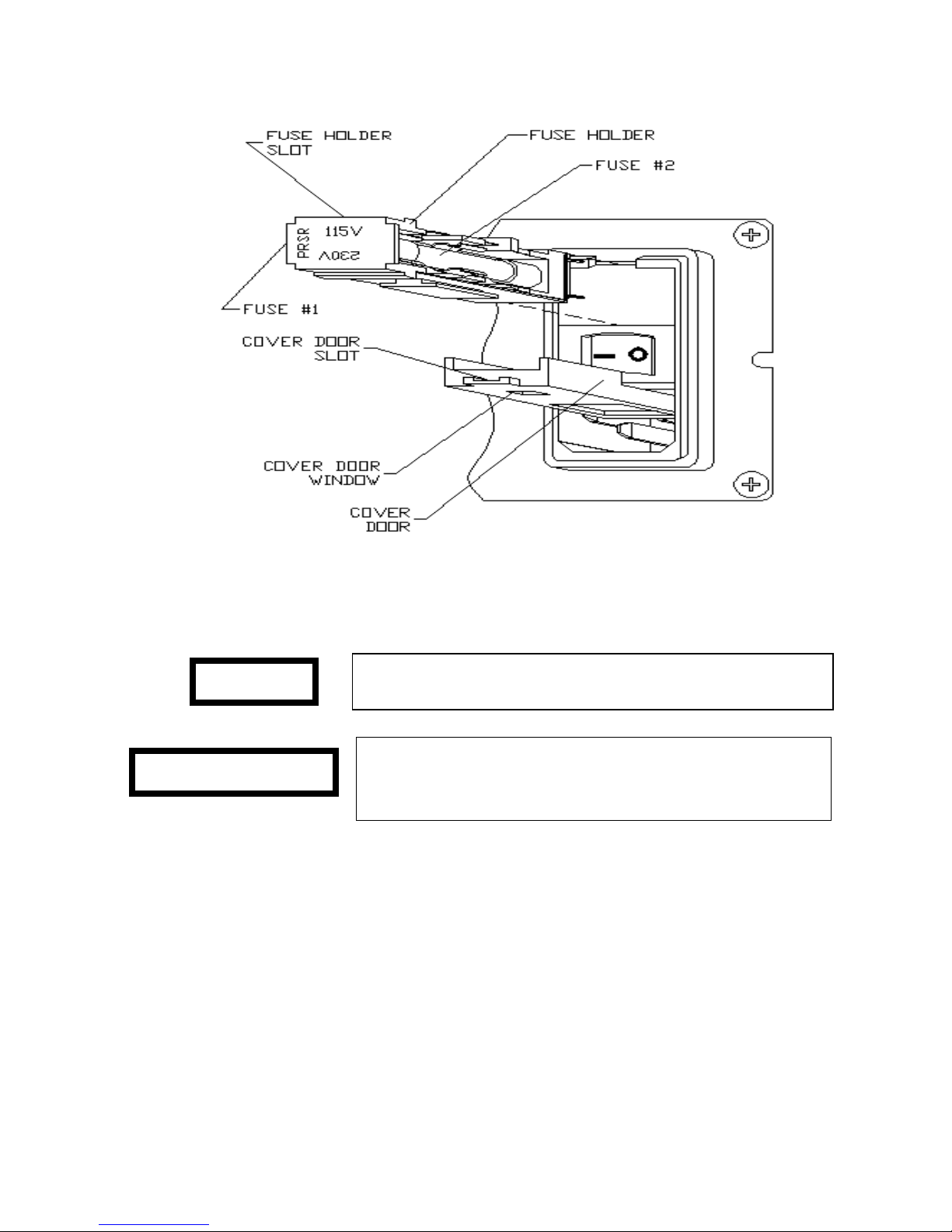
Figure 1: AC Input Module
To avoid injury or death, unplug the line cord from the line
voltage power source before continuing.
WARNING
AVERTISSEMENT
Pour éviter les risques de blessures ou mort, débranchez le
cordon d'alimentation de la source de tension avant de
débuter cette précédure.
Voltage Change
1. Please refer to Figure 1.
2. Repeat steps 1 ─ 6 in Line Fuse Replacement instructions.
3. To change from 115 VAC to 230 VAC, rotate the fuse holder block 180.
4. Replace the two 3AG, 0.5A time-lag fuses with two 3AG, 0.25A time-lag fuses. (Note:
Be sure to change fuses back to 3AG, 0.5A time-lag fuses when changing back to
115VAC).
5. Replace fuse holder block and close the cover door. The desired line voltage will be
indicated in the cover door window.
VCM-D1 User Manual

16
Shutter Fuse Replacement
1. Please refer to Figures 2 for the VCM-D1 front panel layout.
2. A medium flat-bladed screwdriver or similar tool is needed to complete this
procedure.
3. Power the unit OFF and disconnect the line cord from the line voltage power
source.
4. Position the VCM-D1 unit such that the front panel is facing you. If necessary,
disconnect the shutter cable from its 5-pin SHUTTER connector on the rear
panel.
5. Using the screwdriver, or similar, insert the tool into the slot on the SHUTTER
FUSE cap. Apply slight inward pressure and rotate the cap 1/8 turn,
counterclockwise. The fuse cap will pop out slightly.
6. Remove the fuse cap and fuse.
7. Replace the fuse with a known good one. The shutter fuse is a 0.6 A, 5 x 20 mm,
time-lag (slo-blo) type.
8. Reverse the procedure to re-install the fuse cap, reconnect all cables and power
the unit back up.
VCM-D1 User Manual

17
Initial Operation and Testing
Be sure power switch is in the off position before connecting the
power cord to line. Attach line cord to the unit first before
plugging into the AC power source.
WARNING
AVERTISSEMENT
Veuillez vous assurer que le commutateur d'alimentation est en
position OFF (éteinte) avant de brancher le cordon
d'alimentation. Branchez d'abord le cordon d'alimentation à
l'appareil avant de le raccorder à la source de tension
1. The VCM-D1 is manually selectable to operate from 115 VAC or 230 VAC (50-60Hz).
PLEASE BE SURE THAT THE UNIT IS PROPERLY SET UP FOR THE LINE
VOLTAGE TO BE USED. Refer to the Voltage Change section of this manual for
further information and procedures.
2. Once the line cord has been attached to unit and connected to a properly grounded wall
receptacle, the unit may be energized. See Start Up section.
3. Insert the 5-pin male connector of shutter interconnect cable into 5-pin female receptacle
at rear of unit labeled SHUTTER.
4. Connect the 7-pin female connector of shutter-interconnect cable to 7-pin male
connector on shutter to be driven.
5. Place POWER switch to the ON “1” position, the POWER LED will illuminate.
6. Place the N.O./N.C. switch into the N.O. position. The shutter will open and remain
open until the switch is returned to the N.C. position. The green DRIVER LED will
illuminate when this switch is in the N.O. position.
7. All UNIBLITZ drivers provide the circuitry necessary to support shutters equipped with
the solid state synchronization option. Simply plug the shutter-interconnect cable into
the driver. If the shutter is equipped with this option the green LED labeled SYNC will
illuminate when the shutter is in the open position. In addition, the SYNC output BNC
will change to the active state when the shutter is open. The absence of the solid state
synchronization option will inhibit the operation of the SYNC output and SYNC LED.
The remainder of the VCM-D1 systems will not be affected.
8. See SPECIFICATIONS and OPERATOR CONTROLS for additional operational
information concerning other features of the VCM-D1.
9. Should the shutter and/or controller not respond as described previously, be sure line
cord is installed into the receptacle and connections to the shutter are made properly.
Note that the shutter output is also fused, located at the front panel (0.6 A, 5 x 20 mm
VCM-D1 User Manual

18
time-lag). Check these fuses for failure. Please see the Shutter Fuse Replacement
CAUTION
Turn off the unit and remove the plug from the AC source
before checking for blown fuses.
PRUDENCE
Éteignez l'appareil et débranchez le cordon d'alimentation de la
source de tension AC avant de vérifier si les fusibles sont brulés.
section elsewhere in this manual.
10. Be advised, a visual inspection of a fuse is usually NOT an adequate test to determine if
a fuse failure has occurred. Use a DMM (Digital Multi-Meter) or equivalent test device
to determine fuse continuity.
11. Additionally, please note that particular shutter units respond to different minimum pulse
widths. For example, a standard VS25 shutter has a minimum exposure pulse of 6 ms.
If the timing is set for an exposure pulse width less than 6 ms the shutter may not open
fully.
12. If the unit still does not operate properly, turn off and disconnect the unit. Please notify
Vincent Associates immediately. There are no user-serviceable parts outside or inside of
the unit.
VCM-D1 User Manual
 Loading...