

Vimpex VPSU-24-01a, VPSU-24-02a, VPSU-24-03a, VPSU-24-02b/1, VPSU-24-03b/1 Installation Manual
Page 1

Installation Manual for
VPSU-24 Series
24-volt Power Supplies
VPSU-24 Series
VPSU-24-01A
1A – 24 volts
VPSU-24-02A
2A – 24 volts
VPSU-24-03A
3A – 24 volts
VPSU-24-02B/1
2A – 24 volts, with battery charging
VPSU-24-03B/1
3A – 24 volts, with battery charging
Vimpex Ltd
Tel: +44 (0)1702 216999 - Fax: +44 (0)1702 216699
Star Lane – Great Wakering - Essex – SS3 0PJ - UK
www.vimpex.co.uk
Page 2
VPSU-24 Series Installation Instructions VPSU-24/IS-Iss1 - 281111
2
Installation
Mount the metal enclosure onto the wall.
Connect the Live, Earth and Neutral terminals to an un-switched fused spur.
Connect the tamper outputs to the control panel as appropriate (see control
panel manual for details).
Connect the 24v power output to the system.
Fit the battery connectors where appropriate (VPSU-24-02B/1 and VPSU-24-
03B/1 only).
Switch on the AC supply and confirm that the “ON” LED is lit.
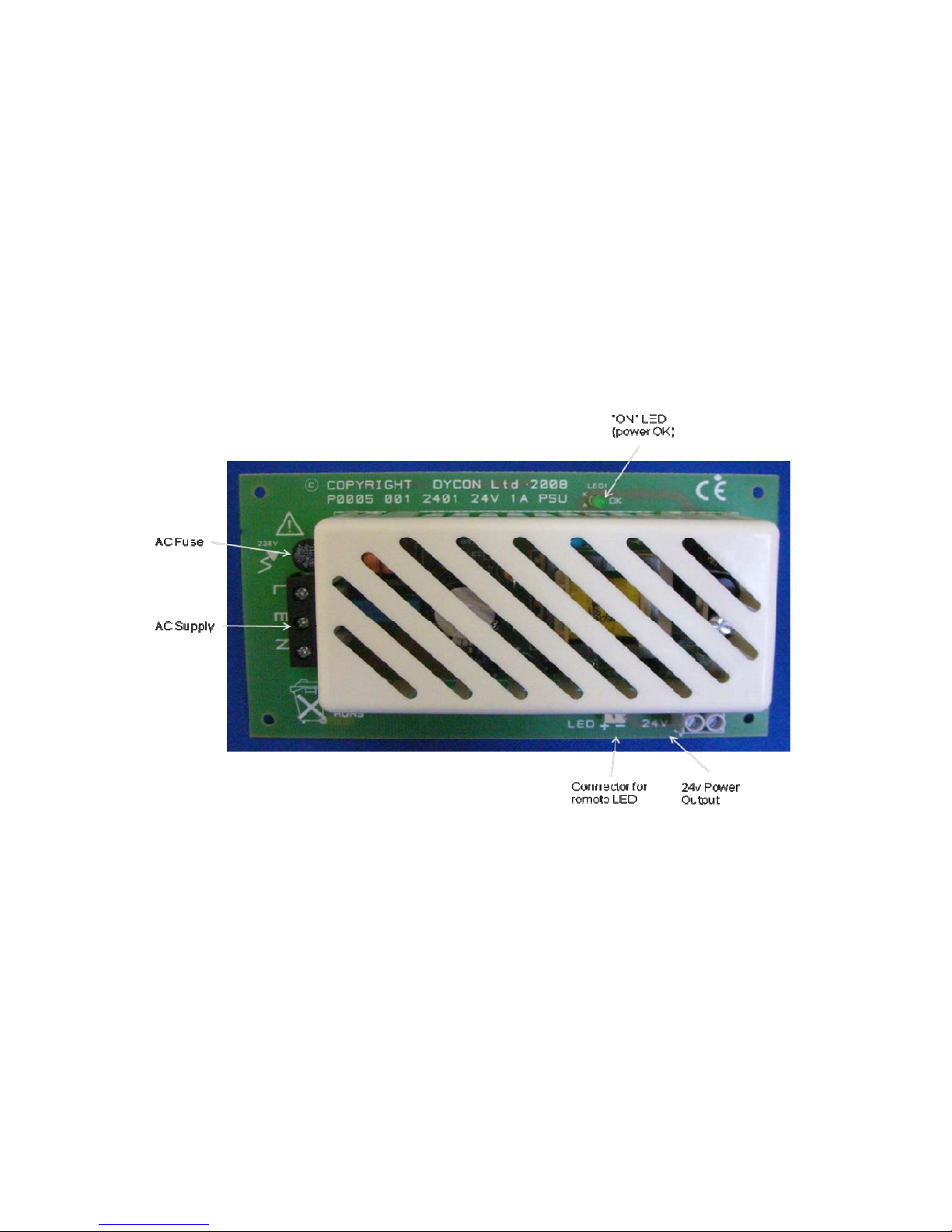
LAYOUT – VPSU-24-01A / VPSU-24-02A / VPSU-24-03A
Page 3
VPSU-24 Series Installation Instructions VPSU-24/IS-Iss1 - 281111
3
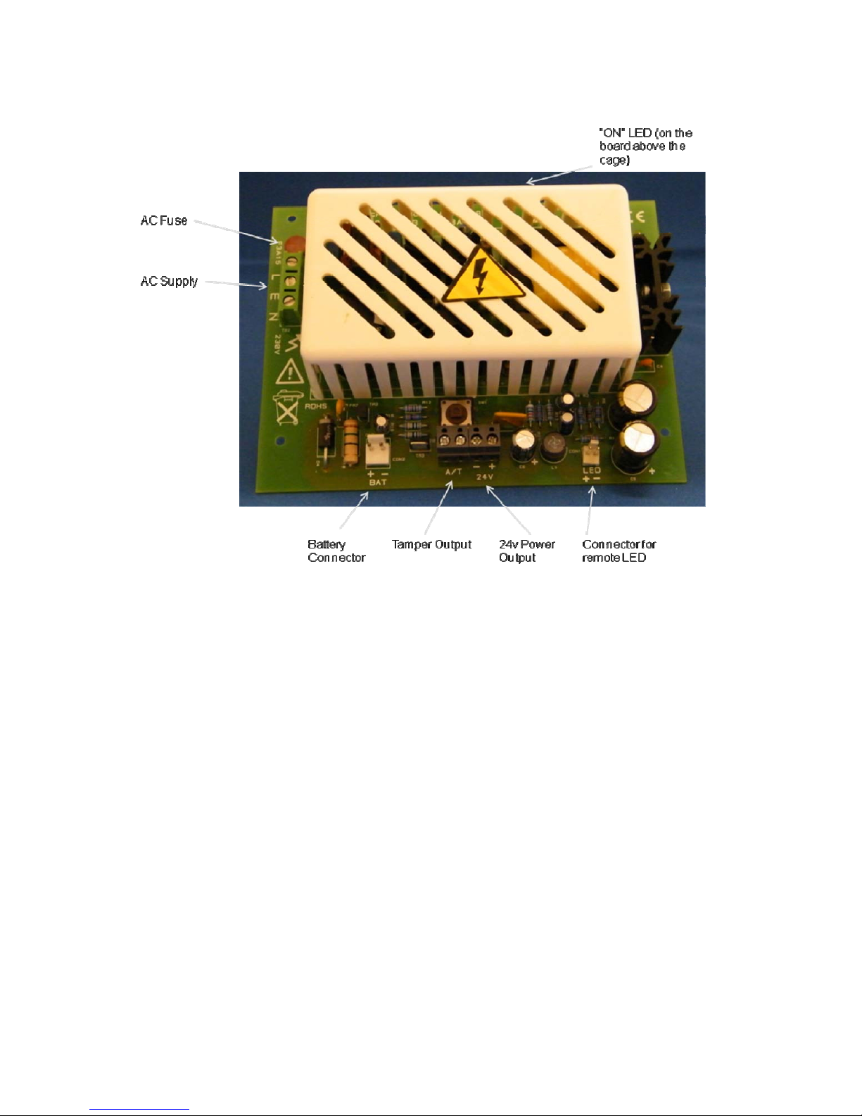
LAYOUT – VPSU-24-02B/1 / VPSU-24-03B/1
External Power Supply (AC Supply)
The power supply has a three-way terminal block for Live, Earth and Neutral
connections, and is protected by a 20mm anti-surge fuse. Mains earth is isolated
from the 0v output, although, when supplied boxed, mains earth is connected to the
metal enclosure.
Tamper Output
This voltage free output is connected to the Tamper Switch. These terminals will be
shorted when the tamper switch is closed.
24V Power Output
Terminal blocks are provided to connect to the system. The “ON” LED indicates
that 24V is available from these terminal blocks.
Auxiliary Power Supply (Batteries)
These power supplies are compatible with 7AH or 8AH Sealed Lead Acid or Gel
batteries which are connected to the “BATT” terminals.
If two batteries are to be used, they must be connected in series.
Page 4

VPSU-24 Series Installation Instructions VPSU-24/IS-Iss1 - 281111
4
Battery Protection
The batteries and electronic circuitry are protected against reverse polarity
connection by a self-resetting electronic fuse.
Maintenance
This unit is to be used by service personnel only; there are no user serviceable
parts. No maintenance is required other than routine periodic testing and
replacement of the standby batteries.
Please note that high voltage is present under the cage – handle with care.
Do NOT touch. Do NOT remove the cage.
For further information on routine battery replacement, please contact your battery
supplier or manufacturer.
Specifications
Power supply Type A, Ungraded, Environmental
Class 2
AC Input voltage 230v +10% -15%, 50Hz ± 15%
AC Input fuse
- VPSU-24-01A
- VPSU-24-02A, VPSU-24-02B/1
- VPSU-24-03A, VPSU-24-03B/1
20mm anti-surge fuse rated at:
- 230V, 1A
- 230V, 2A
- 230V, 3A
Output voltage 24v nominal
Output ripple Less than 100mV
Battery recharge time Less than 72 hours
Operating temperate range -10°C to +40°C
Product Part Numbers
A Box B Box
1 Amp – general purpose
VPSU-24-01A On request
2 Amp – general purpose
VPSU-24-02A On request
3 Amp – general purpose
VPSU-24-03A On request
2 Amp – with battery charging
On request VPSU-24-02B/1
3 Amp – with battery charging
On request VPSU-24-03B/1
Sizes and Weights
PCB “A” Housing “B” Housing
Size (H x W x D mm) 130 x 100 x 38 235 x 170 x 85 260 x 320 x 87
Weight (kg) 0.19 2.0 3.2
 Loading...