

Page 1
User Manual
TAB
40607
TAB 7S IP hands-free video entryphone
Page 2

2
TAB: 40607
EN
CONTENTS
Rules of Installation, Regulatory compliance, WEEE - Information for users ..................................................... 3
1. Description ........................................................................................................................................................... 4
1.1. Technical characteristics ............................................................................................................................. 4
1.2. Main functions ............................................................................................................................................ 4
1.3. Audio frequency function for hearing aids (teleloop) .................................................................................. 4
1.4. Maintenance .............................................................................................................................................. 4
1.5. Disclaimer — Operation of app for TAB 7S IP ........................................................................................... 5
1.6. Description of buttons and main screen ..................................................................................................... 6
2. Introduction ......................................................................................................................................................... 9
3. Call functions ...................................................................................................................................................... 10
3.1 Call from Speech Unit ................................................................................................................................ 10
3.2 Speech Unit self-start ................................................................................................................................. 12
3.3 Calling from or directly to another video entryphone ................................................................................. 13
3.4 Calling from or directly to a switchboard .................................................................................................... 14
4 Settings ............................................................................................................................................................... 15
4.1 General Information ................................................................................................................................... 15
4.2 Display and Buttons ................................................................................................................................... 16
4.3 Sounds ....................................................................................................................................................... 16
4.4 Call Options ............................................................................................................................................... 16
4.5 WiFi ............................................................................................................................................................ 16
4.5.1 ON (station) ....................................................................................................................................... 17
4.5.2 Hotspot (access point) ....................................................................................................................... 17
4.6 Mobile Devices ........................................................................................................................................... 18
4.7 System ....................................................................................................................................................... 19
5 Contacts List ....................................................................................................................................................... 20
5.1 Home ......................................................................................................................................................... 21
5.2 Favourites .................................................................................................................................................. 21
5.3 Users .......................................................................................................................................................... 23
5.4 Speech Units .............................................................................................................................................. 23
5.5 CCTV ......................................................................................................................................................... 23
5.6 Concierge .................................................................................................................................................... 24
5.7 Actuations .................................................................................................................................................. 25
6 Call Log ............................................................................................................................................................... 26
7 Messages ........................................................................................................................................................... 28
8 Video Messages ................................................................................................................................................. 32
9 Alert .................................................................................................................................................................... 34
Page 3

3
TAB: 40607
EN
The instructions manual can be downloaded from the website www.vimar.com
Installation rules
Installation must be carried out in compliance with current regulations regarding the installation of electrical equipment in the
country where the products are installed.
Regulatory compliance
RED Directive
Standards EN 301 489-17, EN 300 328, EN 62311, EN 60065, EN60118-4.
Vimar SpA declares that the reference radio equipment type 40607 complies with Directive 2014/53/EU. The full text of the
EU declaration of conformity is available at the following Internet address: www.vimar.com
WEEE - User information
The crossed bin symbol on the appliance or on its packaging indicates that the product at the end of its life must be
collected separately from other waste. The user must therefore hand the equipment at the end of its life cycle over to
the appropriate municipal centres for the differentiated collection of electrical and electronic waste. As an alternative
to independent management, you can deliver the equipment you want to dispose of to the dealer when purchasing a new
appliance of an equivalent type. You can also deliver electronic products to be disposed of that are smaller than 25 cm for
free, with no obligation to purchase, to electronics retailers with a sales area of at least 400 m2. Proper sorted waste collection
for subsequent recycling, processing and environmentally conscious disposal of old equipment helps to prevent any possible
negative impact on the environment and human health while promoting the practice of reusing and/or recycling materials
used in manufacture.
Page 4

4
TAB: 40607
EN
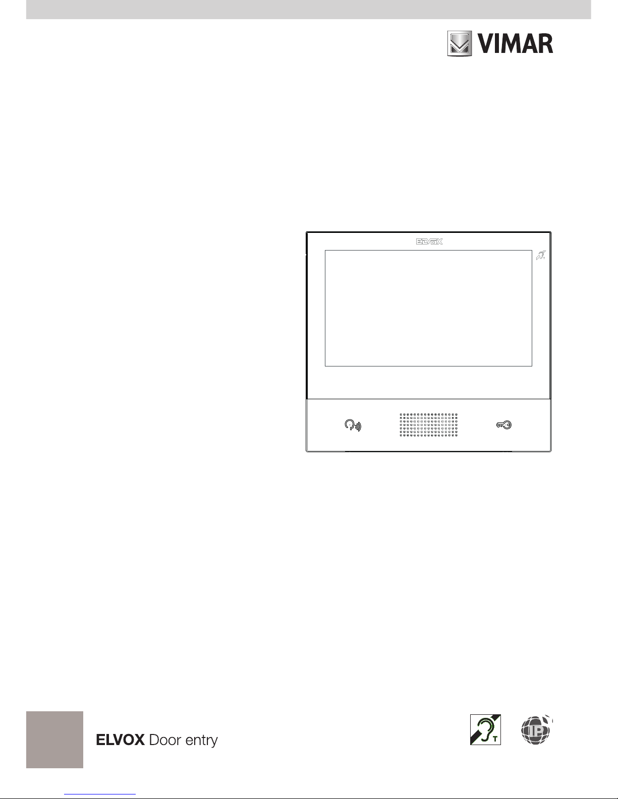
1. Description
Wall-mounted hands-free video entryphone for IP system with colour LCD touchscreen display, capacitive
keypad for entryphone functions and intercom calls, induction loop for hearing aids, bracket for fixing in round
or rectangular mounting box.
1.1. Technical characteristics
• 7-inch display, 800x480, 16M colours.
• Touchscreen + 2 backlit capacitive keys.
• Full-duplex hands-free with echo canceller and teleloop function.
• Assembly: wall-mounting, with metal bracket, in box: circular 2M (Vimar V71701), 3M (Vimar V71303,
V71703) horizontal and vertical, 4+4M (Vimar V71318, V71718) and square, British standard.
• Dimensions: 166 x 184 x 24.2 (wall mounted).
• Supply voltage: PoE, class 0.
• Average PoE consumption: 8 W
• Operating temperature: - 5 to 40°C.
1.2. Main functions
• Receiving video calls from speech unit.
• Speech unit self-starting.
• Speech unit lock opening.
• Intercom audio calls.
• Call transfer.
• Activating system actuations (stair light, auxiliary functions).
• System contacts list and favourites menu for quick access.
• Configurable video voicemail.
• Receiving and sending text messages.
• Multiple ringtones, configurable from those available in the device.
• Adjust audio and video call settings.
• Input for landing bell.
• Mounting frame for IP CCTV integration.
• Mounting frame for remote call service on smartphone/tablet via WiFi connectivity.
1.3. Audio frequency function for hearing aids (teleloop)
The video entryphone can be used by people wearing hearing aids.
For correct functioning of the hearing aid, please refer to its instruction manual. Any metal objects or electronic
equipment in the vicinity may affect the quality of the sound received by the hearing aid.
1.4. Maintenance
Clean using a soft cloth. Do not pour water onto the appliance and do not use any type of chemical product.
Warnings for the user
Do not open or tamper with the appliance.
Page 5

5
TAB: 40607
EN
If a fault occurs, contact specialised personnel.
1.5. Disclaimer — Operation of app for TAB 7S IP
In addition to basic functions, the TAB 7S IP video entryphone supports call repetition and a number of other
services on smartphones and tablets with the Video Door app installed, through connection to a Wi-Fi network
with Internet access that must have the following characteristics:
• 13-channel IEEE 802.11 b/g/n radio (2.4 GHz)
Operating mode:
• STA - Station (ON):
o Networks: OPEN, WEP 64bit (5-character ASCII code), WEP 128bit (13-character ASCII code),
WPA, WPA2, WPA/WPA2 mixed mode
o TKIP and AES ciphers are supported for WPA and WPA2 networks
o WPS function for WPA/WPA2 networks
o Hidden SSIDs are not supported
• AP - Access Point (Hotspot):
o WPA2-PSK AES network
Vimar is not responsible for the selection of technical equipment for accessing the Internet that the Customer
needs to use the service, and which is based on an agreement that the Customer has signed with an Internet
Service Provider (ISP); such agreement may entail costs for using data via the Video Door app, which shall
be borne by the Customer.
Remote interaction and correct operation of the TAB 7S IP via the Video Door app over the Internet may de-
pend on:
a) type, brand and model of smartphone or tablet
b) Wi-Fi signal quality
c) type of household contract for accessing the Internet
d) type of data contract on the smartphone and tablet
Vimar will not be held responsible for any malfunction in the event that one of the above items does not comply
with the specic requirements for operation of the product.
The TAB 7S IP supports a VoIP streaming system, so check that it is not blocked under the terms of the smartphone’s data contract.
Page 6
6
TAB: 40607
EN
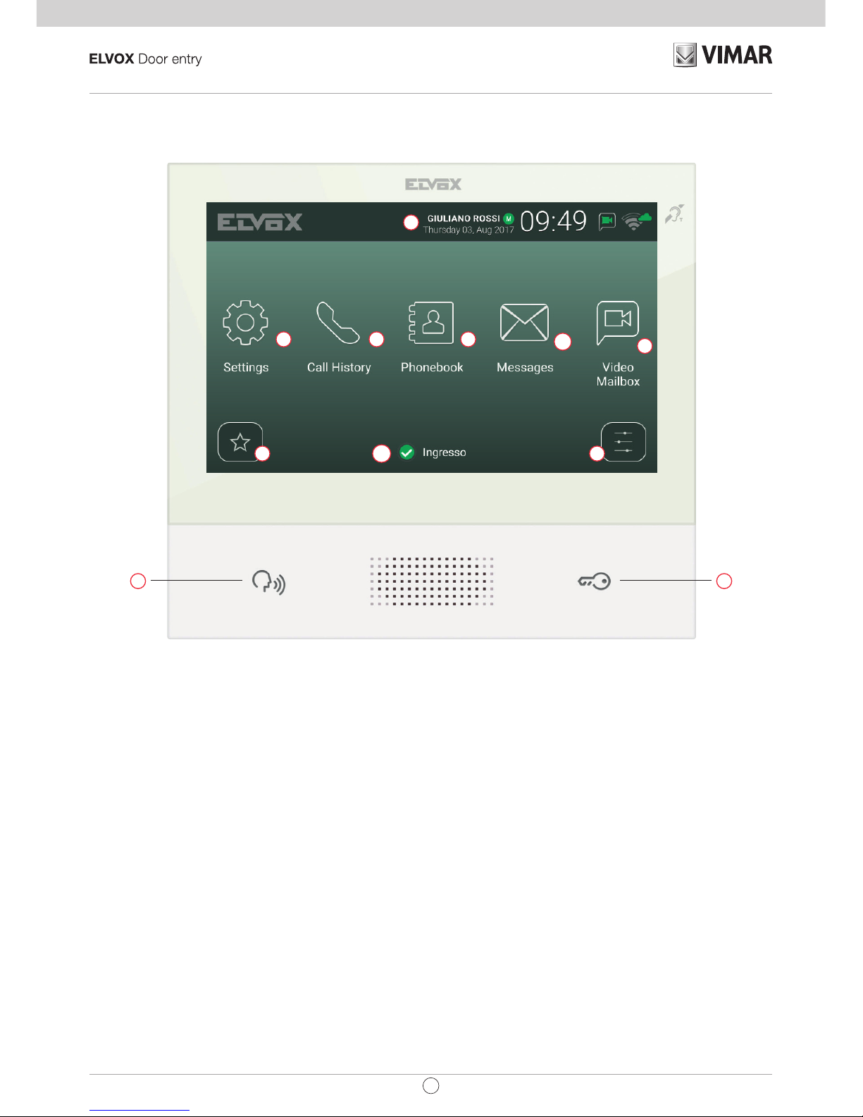
1.6. Description of buttons and main screen
ba
f
i
m
l
d e
g
h
c
Main screen
a) Talk/Listen Button - When an incoming call is received, pressing this button accepts the call. During conversa-
tion, this button toggles between microphone on/off (mute function). In other cases, pressing the button executes
the congured function, e.g. self-start of a specic speech unit.
b) Lock Button - During the call or conversation with the speech unit, pressing the button activates the speech
unit’s lock output, if previously congured. In other cases, pressing the button executes the congured function,
e.g. activating the lock output of a specic speech unit.
c) Header – User name, date and time, master device (M) indication, status icons.
d) Settings – User-congurable parameters: user name, device ID name, interface language, date and time (auto-
matic or manual), display brightness and button backlighting, ringtones, volumes, call options and video voicemail
message. Some of the parameters are only congurable on the user’s master video entryphone.
e) Call log – List of incoming and outgoing calls, including rejected and missed calls.
f) Contacts List – Contains all the contacts in the system divided by type:
Page 7
7
TAB: 40607
EN
• Home: the user’s video entryphones.
• Favourites: contacts selected by the user for quick access from the Favourites menu.
• Users: other system users.
• Speech Units: accessible speech units in the system.
• CCTV: CCTV
cameras congured to be accessible from the video entryphone.
• Porters: porter switchboard stations that can be contacted from the video entryphone.
• Actuations: actuations installed in the system and to which the user has access; they perform functions such as opening locks and turning on service lights.
g) Messages – List of received and sent text messages.
h) Video Messages – List of audio and audio-video messages collected by the video voicemail service.
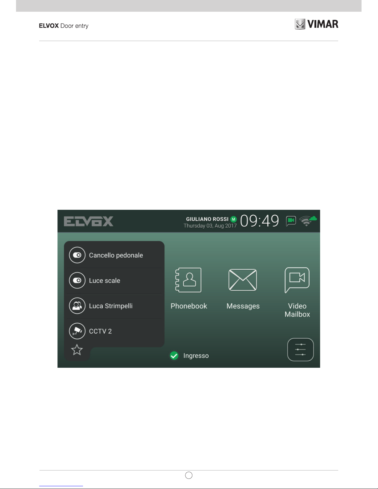
i) Favourites menu – Access to contacts selected by the user: depending on the type of contact you can, for
example, initiate a call or a self-start, activate an actuation or view images captured by a CCTV camera.
Page 8
8
TAB: 40607
EN
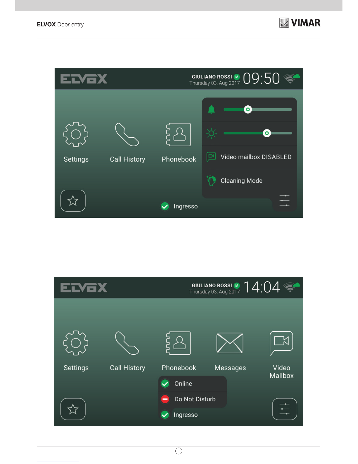
j) Quick settings menu – Access to the main settings: ringtone volume, ringtone on/off, display brightness,
video voicemail service on/off, activate cleaning mode.
k) Status – Displays and allows you to set the user status, i.e. all devices, video entryphones and mobile
devices that belong to the same user: Online or Do Not Disturb. This status is applied to all devices and
can be set using any device. In Do Not Disturb status, all incoming calls are rejected; if the video voicemail
service is enabled, the caller is asked to leave an audio or audio/video message. In Online status, incoming
calls are indicated by a ringtone and visual feedback on the display.
Page 9

9
TAB: 40607
EN
2. Introduction
The video entryphone has a main screen divided into three areas. The header at the top, displaying: user name
(congurable, Primary Name), date, time, and main status icons.
Indicates the master video entryphone.
WiFi mode and Cloud connection status.
Indicates whether the voicemail service is enabled.
Indicates whether ringtone mute is enabled.
In the middle there are ve main icons arranged horizontally. Press one nger down on this area, keep it pressed
and move it to the left or right to display any other available icons that are associated with optional services
(such as Alert). The layout of the icons is customisable: press on an icon and hold your nger down until the
icon enlarges, then drag it to the desired position.
At the bottom there are two drop-down menus and, in the centre, the user Status icon next to the name of the
video entryphone (congurable, Device ID). Pressing the icon changes the Status
to Online or Do Not Disturb.
The same user can be associated with multiple video entryphones, and even mobile devices (smartphones or
tablets) on which the Video Door app by Vimar has been installed. When the system is congured, one of the
user’s video entryphones is assigned as the master device. Certain user settings such as WiFi connectivity are
only accessible from the master device. Other settings can be performed on any video entryphone or mobile
device, but affect all of the user’s devices, such as setting the Status or activating the voicemail service.
Page 10
10
TAB: 40607
EN
3. Call functions
3.1 Call from Speech Unit
When a call from Speech Unit is made to a user, if the user's Status is Do Not Disturb and the video voicemail
service is enabled, the call is automatically rejected or diverted to voicemail. The video entryphone does not
ring or display any image.
Whereas, if the Status is Online, all devices associated with the user (video entryphones and mobile phones)
are notied of the call in progress: the screen displays images captured by the Speech Unit camera and the
video entryphone plays the congured ringtone. If the ringtone is off (Quick settings menu), the video entryphone
does not play any sound.
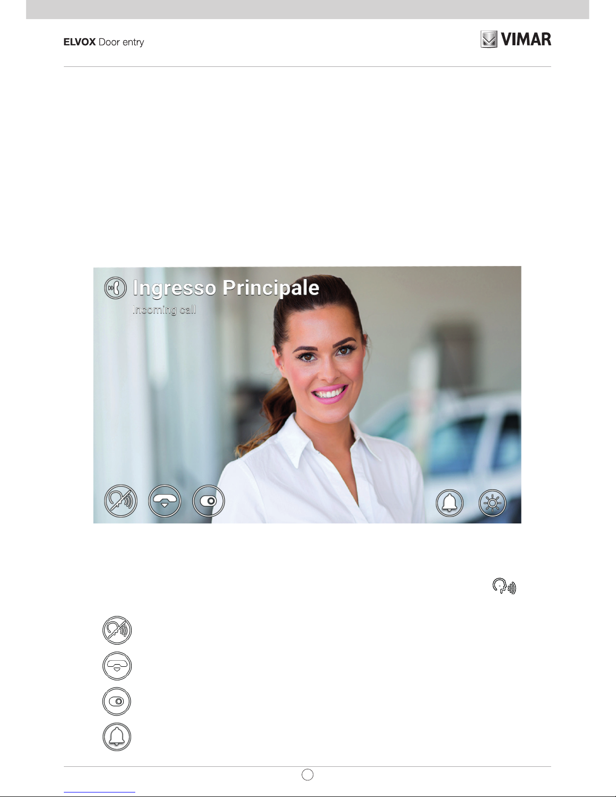
Incoming call
The name of the calling Speech Unit and the call status are indicated at the top of the screen. Use the icons/com-
mands displayed at the bottom of the screen to handle the call. You can also answer by pressing the
button.
To answer the call.
To reject the call.
To perform an actuation selected from a drop-down menu.
To disable the ringtone for the current call.
Page 11
11
TAB: 40607
EN
To adjust the display brightness using the pop-up slider.
If the user presses reject, the call is cut off and all devices return to standby. If the user answers the call, conversation starts between the Speech Unit and the device that the user answered from, while the other devices
return to standby. If answer/reject are not pressed and the voicemail service is enabled, the call is automatically
forwarded to the voicemail after a time corresponding to the Video Voicemail Start Timeout. If the voicemail
service is disabled, the call is cut off after the system timeout expires.
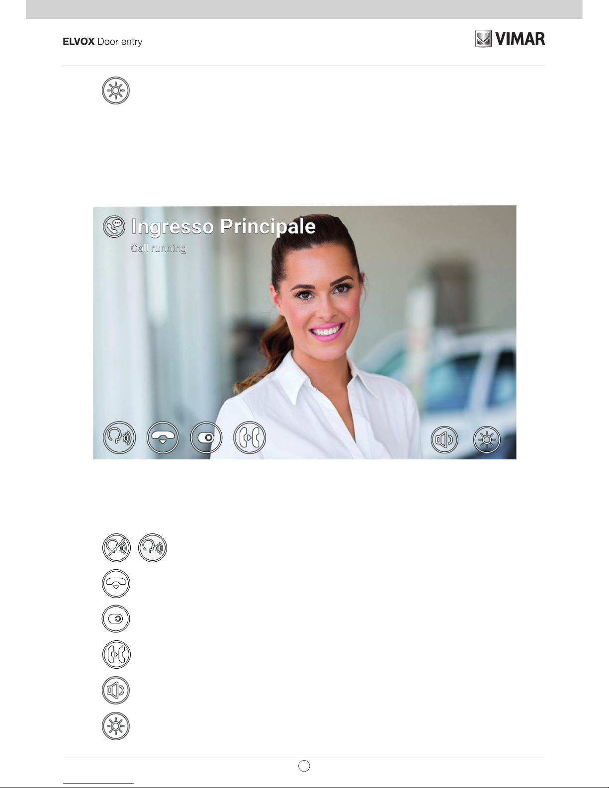
Conversation with speech unit
The following icons/commands are available during the conversation.
To disable/re-enable the microphone (mute function).
To end the call.
To perform an actuation selected from a drop-down menu.
To forward the call to another user or device that can be selected from the drop-down menu.
To adjust the speaker volume using the pop-up slider.
To adjust the display brightness using the pop-up slider.
Page 12

12
TAB: 40607
EN
Both when calling and during the conversation, pressing the button activates the lock output of the calling
Speech Unit (if the function was congured by the installer). Additionally, if the End Call With Key Buttonoption
is enabled, the call is rejected (incoming) or ended (call in progress).
3.2 Speech Unit self-start
In standby with the screen on or off, pressing the button activates self-start of a specic Speech Unit:
this function is only available if enabled by the installer during the system conguration phase.
Self-start of a Speech Unit can also be activated from the Contacts List and Favourites Menu. The conversation
is started with the microphone muted and has a maximum duration congured by the installer. The same icons/
commands described above are available on the screen except for the forwarding function. An additional icon
displays the remaining time. Pressing this icon renews the self-start time.
To restart the self-start end timer.
When the timer expires, self-start is ended and the video entryphone returns to standby.
Self-start
3.3 Calling from or directly to another video entryphone
It is possible to make and receive calls from/to other users belonging to the same video entryphone system.
Enter the Users section of the Contacts List, select the contact and start the call by pressing the corresponding
icon. Calls are audio only. The dynamic and icons/commands are the same as those described for the case of
Page 13

13
TAB: 40607
EN
outgoing calls.
It is also possible to send and receive calls from/to other devices (video entryphones or mobiles) belonging to
the same user. Enter the Home section of the Contacts List, select the device and start the call by pressing
the corresponding icon. In this case, the settings relating to Status (Online/Do Not Disturb) and to the video
voicemail service (on/off) are irrelevant.
Conversation with indoor unit
3.4 Calling from or directly to a switchboard
If one or more porter switchboard stations have been installed in the video entryphone system, it is possible
to send and receive calls from/to the switchboard. If the station is equipped with a video camera, the calls will
be audio-video, otherwise they will be audio only. The dynamic and icons/commands are the same as those
described for the case of outgoing calls.
Page 14

14
TAB: 40607
EN
Conversation with switchboard
Page 15

15
TAB: 40607
EN
4 Settings
The Settingspage, which is accessed by pressing the button on the main screen, allows you to customise
and congure some parameters of the video entryphone system. The page is divided into the following sections:
General
Displays and Buttons
Sounds
Call Options
WiFi
Mobile Devices
System
Selecting a section displays the items contained therein. To scroll through the items, press your nger on the
list and move it up or down while keeping it pressed.
Some of these sections and items (specically referred to below) are accessible or congurable only on the
master video-intercom device.
4.1 General Information
• Primary Name (from master device only): to set the primary name associated with the user. When con-
guring the system, the installer assigns a preliminary name to the user (e.g. "Apartment 1"). The user
can change it later, by using the virtual keyboard on the screen to type and save the desired name (e.g.
"John Smith"). This is the name by which the user is identied in the system contact lists. The name is
displayed in the header area of the main screen on all video entryphones belonging to the user.
• Secondary Name and Additional Names
(from master device only): to set the secondary name and any
additional names or information. Information about the user is displayed by the porter switchboard as
follows:
• Reset Names (from master device only): to reset the names to the default values (e.g. "Apartment 1"
for the Primary Name, and blank for the Secondary Name and Additional Name).
• Device ID: to set the ID by which the individual video entryphone is identied from among the user’s
devices. Each video entryphone has its own ID, which is automatically assigned during system congu-
ration (e.g. PI_60001 for the master device). The user can subsequently change it to a name of their
choice (Entrance, Study, etc.). In the Home section of the Contacts List, each user's video entryphone
is identied by its Device ID. In the main screen, the ID appears at the bottom, next to the status icon.
• Language: to select the language used by the video entryphone interface. The following languages are
available: Italian, English, French, German, Spanish, Greek and Portuguese.
Page 16

16
TAB: 40607
EN
• Date and Time (from master device only): to set the date and time displayed in the Header area of the
main screen on all video entryphones belonging to the user. Enabling automatic mode (recommended)
synchronises the video entryphones with the date and time of the video entryphone system. You can
also congure the time zone, time format (12 or 24 hours) and date format.
4.2 Display and Buttons
• Sound Buttons: to activate/deactivate sound feedback when pressing buttons and the screen.
• Button Brightness: to adjust the brightness of the button backlighting.
• Standby Button Light: to enable/disable button backlighting in standby.
• Display Brightness: to adjust the brightness of the display.
• Shutdown Timeout: to set the amount of idle time before standby.
• Graphic Theme: to select the graphic theme.
4.3 Sounds
• Ringtones: to select the desired ringtone based on the type of call received. There are ten ringtones to
choose from. The call types are: from Speech Unit, from Porter (porter switchboard), from Users (other
system users), Intercom (call from another of the user’s devices), Bell (call via dedicated Landing call
input).
• Ringtone Volume: to adjust the ringtone volume (same for all call types).
• Button Volume: to adjust the volume of the button press sound effect.
4.4 Call Options
• End Call With Key Button: if this option is enabled, when receiving a call from Speech Unit, pressing the
Key button activates the Speech Unit lock and simultaneously cuts off the call (even during conversa-
tion).
• Video Voicemail Start Timeout (from master device only): to set the standby time in seconds before
the voicemail service (if activated) is triggered when a call is unanswered. If the user status is Do Not
Disturb and the service has been activated, the voicemail function will start immediately when a call is
received.
• Video Voicemail Message (from master device only): to record and listen to the introductory message
of the voicemail service (length 10 seconds). When the voicemail service activates, this message is
played by the calling device before recording starts.
4.5 WiFi
This section is only accessible on master devices. If WiFi connectivity is enabled, the video entryphone also
allows the user to access video entryphone services from a mobile device (smartphone or tablet) on which the
Video Door app by Vimar has been installed.
If you have a home WiFi network via your own router or access point, select ON mode and follow the instructions in the next paragraph, 3.5.1. If you do not have a WiFi network, select Hotspot mode and refer to the
information in paragraph 3.5.2.
Finally, complete the association procedure between the mobile device and the master video entryphone as
described in section 3.6.
Page 17

17
TAB: 40607
EN
4.5.1 ON (station)
In this mode, the video entryphone connects to an existing WiFi network. Select the network to join from the list
of available networks. If the network is encrypted, the virtual keyboard is displayed so that you can type and
conrm the password (top right of the screen). Alternatively, you can use the WPS procedure if supported by
your router or access point.
• Network: to display a pop-up message with information about the WiFi network selected for the con-
nection (SSID, status, IP address, channel, signal level).
• WPS Connection: to start the association to the router or access point according to the WPS stand-
ard (WiFi Protected Setup, Push Button Conguration method).
• WiFi Networks List: list of available WiFi networks.
4.5.2 Hotspot (access point)
Use this mode only if you do not have a WiFi network: the master video entryphone functions as an access point.
After the Video Door app is installed on the mobile device, the wizard automatically congures the mobile WiFi
network so that it connects to the video entryphone access point. During the procedure, when prompted by the
Connection Wizard, select Show QRCode and scan the QR code displayed on the video entryphone screen
with your mobile phone’s camera.
QR Code Hotspot
NOTE: this WiFi connectivity does NOT provide access to the Internet, but only to video entryphone services.
• SSID: SSID ID of the video entryphone’s WiFi network.
Page 18

18
TAB: 40607
EN
• Channel: to set up the WiFi channel (recommended: Auto).
• Password: to set the network password.
• Connected Devices: the number of devices connected to the network.
• Show QRCode: to display a pop-up with the QRCode needed to complete the Connection Wizard on
the Video Door app.
4.6 Mobile Devices
This section is accessible only on the master device and only after enabling WiFi in one of the two modes
described above. To access video entryphone services, you must associate your mobile device with the video
entryphone user. Each user can be associated with up to 3 devices.
If your WiFi network accesses the Internet via a router, activating CLOUD Services enables you to use the Video
Door app even when the mobile device is not connected to your home network (however, it must be connected
to the Internet through another WiFi network or other type of connectivity). The Online CLOUD Status indicates
that the services have been properly activated and the function is available.
After installing the Video Door app on your mobile and completing the Connection Wizard, follow the Congura-
tion Wizard instructions: the mobile phone and video entryphone must be connected to the same WiFi network
during the association procedure. Select one of the three available slots in the Mobile Devices List, then press
the
icon. Use your mobile phone to scan the QRCode displayed on the screen of the video entryphone
and wait for feedback conrming the association. Finally, the name assigned to the device is displayed in the
selected slot in the Conguration Wizard. The same name is added to the Home section of the Contacts List.
QR Code Mobile Setup
If you want to cancel the association with a mobile device, select the corresponding slot and press the
icon. The mobile device will no longer be able to access the services unless the whole association process is
Page 19

19
TAB: 40607
EN
repeated.
• CLOUD Services: to enable/disable CLOUD services.
• CLOUD Status: status of CLOUD services.
• Mobile Devices List: mobile devices already associated with the video entryphone system and/or slots
available for associating new devices. The available slots are identied by the following names: Mobile
Device1, Mobile Device2, Mobile Device3.
4.7 System
• Firmware Version: version of the video entryphone’s rmware.
• IP Address: IP address (and MAC address) of the video entryphone.
• Restart: to restart the device.
• Reset Settings: to restore all user settings to the default conguration, except for Names. For these,
use the dedicated command Reset Names in the General section.
• Factory Reset: to restore all settings to the factory conguration. The administrator password must be
entered to perform this operation. CAUTION: the installer's assistance will be required to recongure
the video entryphone and make it usable again.
Page 20

20
TAB: 40607
EN
5 Contacts List
The Contacts List contains all the contacts in the system to which the video entryphone has access. The
contacts are divided by type into the following sections:
Home
Favourites
Users
Speech Units
CCTV
Porters
Actuations
Selecting a section displays the contacts contained therein. To scroll through the contacts, press your nger
on the list and move it up or down while keeping it pressed. After selecting a contact, the icons/commands
related to the specic contact appear on the right.
To display a pop-up with the contact’s detailed information
To add/remove the contact from the favourites
To send a text message to the contact
To call the contact
To remove the contact from the favourites
To activate the speech unit lock output
To display images captured by the CCTV
To activate the actuation
Page 21

21
TAB: 40607
EN
Contacts List
5.1 Home
Contacts relating to video entryphones and mobile devices belonging to the same user. This section always
contains the special contact All My Devices, which allows you to call or send a message to all your user's
devices.
If you have multiple video entryphones, or if the user has been associated to mobile devices, a contact is
displayed for each one. The contact is identied by the Device ID in the case of video-intercoms, and by the
name congured during association in the case of mobile devices. The section does not show the Device ID
of the video entryphone on which you are currently browsing the Contacts List.
The following commands are available for contacts in this section:
, , , .
5.2 Favourites
Contacts selected by the user as "favourites". These contacts are also displayed in the Favourites Menu on
the main screen, to facilitate instant access. They can be of any type, and also appear in another section of
the Contacts List, divided by type.
Select a contact from any of the other sections and press the
icon: the contact becomes a "favourite"
and the icon changes colour to
. The contact is automatically added to the Favourites section, as well
as to the Favourites Menu.
Page 22

22
TAB: 40607
EN
To remove it from the Favourites, press : the icon changes to and the contact is removed from
the Favourites section and the Favourites Menu. Alternatively, you can also remove it by selecting the contact
in the Favourites section and pressing the
icon.
Contacts List - Favourites Section
When selecting a contact from the Favourites Menu, a specic action is performed depending on the type of
contact:
• Home, Users and Switchboards: initiates call to the contact.
• Entry Panels: initiates auto-start of the speech unit.
• CCTV: displays images captured by the camera.
• Actuations: activates the actuation.
Page 23

23
TAB: 40607
EN
Favourites Menu
5.3 Users
Contacts relating to other system users to which you can initiate a call or send a message.
The following commands are available for contacts in this section:
, , , .
5.4 Entry panels
Contacts relating to speech units to which you can initiate a self-start. If the user has been enabled by the
installer during the system conguration phase, it is also possible to activate the speech unit’s lock output.
The following commands are available for contacts in this section:
, , , .
5.5 CCTV
Contacts relating to cameras for which you can view captured images.
The following commands are available for contacts in this section:
, , .
When camera image view is activated, the name of the camera is indicated at the top of the screen, and
icons/control commands are available at the bottom of the screen. The maximum duration is congured by
the installer: a special icon displays the remaining time and pressing it enables the viewing duration to be
extended. When the timer expires, the video entryphone returns to standby.
Page 24

24
TAB: 40607
EN
To stop viewing.
To restart the viewing end timer.
To adjust the display brightness using the pop-up slider.
CCTV display
5.6 Switchboards
Contacts relating to porter stations to which you can initiate a call or send a message.
The following commands are available for contacts in this section:
, , , .
5.7 Actuations
Contacts relating to actuators (lock outputs and relay outputs) that can be activated. The activation request
is conrmed by a feedback icon, which is displayed in the centre of the screen for a few seconds. The image
(selected by the installer) can be one of the following:
Page 25

25
TAB: 40607
EN
Feedback icons
The following commands are available for contacts in this section:
, , .
Page 26

26
TAB: 40607
EN
6 Call Log
The Call Log is organised into two sections, All calls and Missed calls. The rst section lists all outgoing and
incoming calls. The second section lists only rejected calls and those that the user did not answer. For each
section, the
icon can be used to respectively delete the history of all calls, or to delete missed calls only.
Call log
The name of the recipient/caller, date and time are shown for each entry. In the case of missed calls, the name
is displayed in red next to the
icon. Outgoing calls are instead identied by the icon.
To scroll through the items, press your nger on the list and move it up or down while keeping it pressed. After
selecting an item, the following icons are displayed on the right:
to remove the entry from the history,
and
to initiate a new call to the contact.
When you have new missed calls, the number of calls is shown on the main screen above the Call Log icon. If
the device is in standby with the screen off, the backlight of the
button ashes to indicate new missed
calls. Both indications stop being displayed when you access the Call Log.
Page 27

27
TAB: 40607
EN
Main screen - New missed calls
If the user's State is Do not Disturb, automatically rejected calls are not recorded in the history. If the State
is Online and the video voicemail service is enabled, calls forwarded to the voicemail service are recorded as
missed calls.
Page 28

28
TAB: 40607
EN
7 Messages
Incoming and outgoing sent messages are contained in the Received and Sent sections. The icon
enables you to delete the messages in each section.
Messages
The sender/recipient name, date, time and a preview of the message content are indicated for each message
in the list. If an image is attached to the message, a paper clip icon is displayed next to the name. The
symbol indicates new messages that have not yet been opened. In the case of Alert messages received by a
porter station, the sender's name is displayed in red.
To scroll through messages, press your nger on the list and move it up or down while keeping it pressed. Select
a message to open it: the entire contents of the message and any attached images are displayed. The
and
icons/commands on the right respectively allow you to delete the message and reply to the sender
(or, if viewing a sent message, to send a new message to the same recipient) by opening the New Message
window.
Page 29

29
TAB: 40607
EN
Message received display
To write a message, access the New Message window using the
New command. The window contains two
areas: selecting the rst area displays a multiple choice list which is used to choose recipients from those available in the Contacts List; selecting the second area displays a virtual keyboard which is used to write the mes-
sage. After typing the text, conrm by selecting In the upper right corner, then send the message using
the
icon/command. Alternatively, allows you to delete the message being typed (recipients and
content).
Page 30

30
TAB: 40607
EN
Write new message
Text messages must contain no more than 160 characters. Images cannot be attached to sent messages.
Sending a message to multiple recipients equates to sending the same message to each recipient, and the
corresponding details are recorded in the Sent Items section.
When you have new unopened messages, the number of messages is shown on the main screen above the
Messages icon. If the device is in standby with the screen off, the backlight of the
button ashes to
indicate new unread messages. Opening new messages cancels both visual indications.
Main screen - New text messages
Page 31

31
TAB: 40607
EN
8 Video Messages
The page shows messages recorded by the voicemail service. The icon next to Video Messages allows
you to delete all messages.
Voicemail
The caller name, date and time are indicated for each message in the list. The
symbol indicates new messages that have not yet been opened. Messages can be audio-video or audio only, depending on the type of
caller.
To scroll through messages, press your nger on the list and move it up or down while keeping it pressed. After
selecting a message, the following icons/commands appear on the right:
to delete the message and
to play it. The following icons/commands are available when viewing the message.
To stop viewing.
To adjust the speaker volume using the pop-up slider.
To adjust the display brightness using the pop-up slider.
Page 32

32
TAB: 40607
EN
Play recorded video message
The video entryphone can store up to 100 messages. If the message box is full, the active answering service
icon in the main page header turns red. Additionally, a warning message appears on the Video Messages page.
At least one message must be deleted to allow the service to record new messages.
Main screen - New voicemail messages, box full
Page 33

33
TAB: 40607
EN
9 Alert
This icon/command allows you to send an instant notication to all the porter stations in the system. A pop-up
prompt asks you to conrm before sending. The porter switchboard service treats this notication as a high
priority service request.
Conrmation pop-up
If there is no porter station installed in the video entryphone system, this service is unavailable and the Alert
icon/command
is not displayed on the main page.
Page 34

Viale Vicenza 14
36063 Marostica VI - Italy
www.vimar.com
49400925A0_MU_EN 01 1701
 Loading...