

Page 1

Installer manual
RS16.P
24 Vdc control unit for sliding gate ACTO 404D
Page 2

2
RS16.P
EN
Contents: Page
1 - Product characteristics ................................................................................................................................................................................................ 1
2 - Example of installation ................................................................................................................................................................................................ 1
3 - Description of the terminal blocks ............................................................................................................................................................................... 2
4 - Connecting accessories .............................................................................................................................................................................................. 3
5 - Changing the programmable parameters ................................................................................................................................................................... 5
6 - Trimmer functions ....................................................................................................................................................................................................... 6
7 - Functions of the buttons .............................................................................................................................................................................................6
8 - DIP-switch functions ................................................................................................................................................................................................... 6
9 - LED functions .............................................................................................................................................................................................................. 7
10 -
Remote control programming ..................................................................................................................................................................................... 7
Page 3

1
RS16.P
EN
1 Product characteristics
Control unit for governing sliding gear motors at 24 Vdc with a maximum power of 80 W for gates of maximum length 6 m and 400 kg in weight,
equipped with integrated magnetic limit switches on the board, encoder (used for obstacle detection) integrated receiver at 433 MHz and integrated
battery charger.
The control unit enables:
- customizing the space and speed of deceleration
- equipped with obstacle detection system
- LED for input diagnostics
- integrated receiver with capacity for 50 remote controls (hard coded or rolling code)
- current control for electric motor protection
Tecnichal characteristics
Supply 120 ÷ 230 Vac
Motor power supply 24 Vdc
Maximum motor power 80 W
Output for flashing light 24 Vdc 10 W max
Accessories power supply 24 Vdc 300 mA
Receiver memory 50 remote controls
Receiver frequency 433 MHz
Remote controls code Rolling code or fixed
Fuse F1 (line protection) 5x20 mm T1.6 A
Operating temperature -10 ÷ +50°C
2 Example of installation
Components for creating a complete system with ESM7 or EK14 kit
Main Components Accessories (optional)
Description Article Ref. Qty Components in kit EK14 Description Article Ref. Qty
Operator ESM7 A 1 YES Key switch EDS1 F 1
Flashing light ELA5 B 1 YES Post-mounted photocells EFA3 G 1
Remote control ETR5 C 1 YES Posts EE21 H 2
Wall-mount photocells EFA3 D 1 YES
Pack of 2 batteries 12 V 1.3 Ah
and wiring harness
ZBA7 1
Rack ZE03/1 E 4 (4 m) NO
A
C
B
D
E
F
4x0.5 mm²
2x0.5 mm²
D
G
H
G
H
2x1 mm²
3x0.5 mm²
4x0.5 mm²
2x0.5 mm²
3x1.5 mm² (230 Vac)
Page 4
2
RS16.P
EN
ON
12
345678
N
N
F
-
+
L
SW1 SW2
PHC PHO STP
MRX
PWR
51
PRGMRX
+B
-B
-B
+B
ANT
_
ANT
_
MOTOR
ENCODER
51
52
62
63
61
99
17
0
11
1
0
F1 (5x20) T 1.6A
B
A
C
D
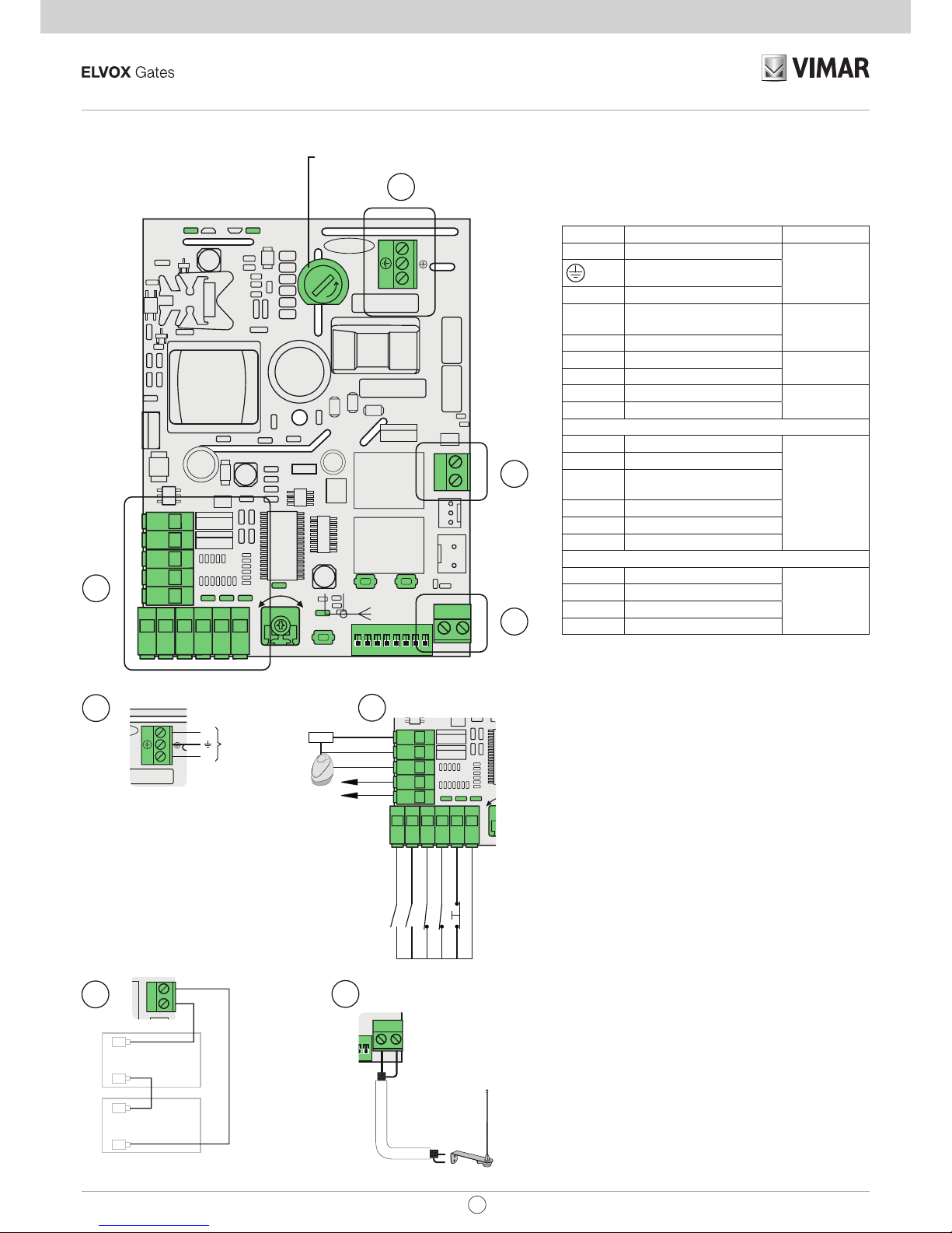
3 Description of the terminal blocks
ON
12
345678
N
N
F
-
+
L
SW1 SW2
PHC PHO STP
MRX
PWR
51
PRGMRX
+B
-B
-B
+B
ANT
_
ANT
_
MOTOR
ENCODER
51
52
62
63
61
99
17
0
11
1
0
SCA
PHC PHO STP
17
0
11
1
0
24V-
24V+
24V-
BLINK+
SCA+
C
N
N
F
L
L
N
230 Vac
120 Vac
-+
12 Vdc
1,3Ah
+B
-B
-B
+B
R
ANT
_
ANT
_
M
F1 (5x20) T 1.6A
B
B
A
A
C
D
D
PED
P. P.
PHC
PH
STOP
COM
ON
12
345678
N
N
F
-
+
L
PHC PHO STP
MRX
PWR
51
PRGMRX
+B
-B
-B
+B
ANT
_
ANT
_
MOTOR
ENCODER
61
99
SCA
-
PHC PHO STP
51
52
62
63
61
99
17
0
11
1
0
24V-
24V+
24V-
BLINK+
SCA+
C
-+
-+
12 Vdc
1,3Ah
12 Vdc
1,3Ah
+B
-B
-B
+B
R
ANT
_
ANT
_
M
F1 (5x20) T 1.6A
B
A
C
D
D
N
F
+B
-B
-B
+B
ANT
_
ANT
_
MOTOR
ENCODER
C
-+
-+
12 Vdc
1,3Ah
12 Vdc
1,3Ah
+B
-B
-B
+B
R
ANT
_
ANT
_
M
C
D
D
ANT
_
ANT
_
M
D
Terminal Description Rated data
N Neutral
120÷230 Vac
Earth
L Phase
17 Photo-test or gate open
warning light positive
24 Vdc 120 mA
0 Accessories negative
11 Flashing light positive
24 Vdc 10 W
0 Accessories negative
1 Accessories positive
24 Vdc 300 mA
0 Accessories negative
51 Step by step (N.O.)
52 Pedestrian (N.O.)
62 Photocell when closing
(N.C.)
63 Photocell (N.C.)
61 Stop (N.C.)
99 Common inputs
-B Emergency battery negative
+B Emergency battery positive
ANT Aerial signal
- Aerial earth
Page 5

3
RS16.P
EN
3.1 Description of output function
0-1 Accessories power supply:
Permanent 24 V DC output.
0-11 Blinking:
24 Vdc output powered when the gate is moving.
0-17 Photo-test or gate open warning light:
24 V DC output for signalling gate status or performing the safety test:
With DIP 8 = OFF it is Gate Open Warning Light
- Not powered with gate closed
- Powered continuously with gate open or moving
With DIP 8 = ON it is Photo-test
Used for the power supply of the transmitters of the safety devices.
Note:
Using the photo-test requires specic wiring of the safety devices (par. 4.3).
3.2 Description of input function
51 Step by step (N.O.):
Sequential command input, to control the complete travel of the gate. It works with the following cycle: open-stop-close-stop or open-stopclose-open according to the setting of DIP 3
52 Pedestrian (N.O.):
Command input for opening to the pedestrian distance.
61 Stop (N.C.):
Gate stops, does not turn o automatic closing.
If not used, jumper with the common (99)
62 Photocell when closing - PHC (N.C.):
Photocell when closing, with the gate stationary it allows opening, when opening it does not trigger, with the gate open it does not allow
closing and on release it resets the automatic closing time, when closing it commands immediate reopening.
If not used, jumper with the common (99)
63 Photocell - PH (N.C.):
Functions according to the DIP 6 setting.
DIP 6 = OFF: photocell, active both when closing and when opening, with the gate stationary it does not allow opening, during opening it
stops the movement and on release it continues opening, with the gate open it does not allow closing and on release it resets the automatic
closing time, when closing it stops the movement and on release it commands reopening.
DIP 6 = ON: safety sensitive edge, N.C. dry contact, with the gate stationary it does not allow opening, when opening it disengages, with
the gate open it does not allow closing and on release it resets the automatic closing time, when closing it disengages.
If not used, jumper with the common (99).
4 Connecting accessories
4.1 Key switch and control devices
EDS1
Step by step
Pedestrian
COM COM
N.O. N.O.
N.C. N.C.
996163625251
PED
COM
P. P.
Page 6

4
RS16.P
EN
-
+
24V-
24V+
-
+
NO
-
+
COMNC
(FSW)
NO
-
+
COMNC
(FSW)
PHC
PH
COM
RX1 RX2TX1 TX2
-
PHC PHO STP
51
52
62
63
61
99
17
0
11
1
0
4.2 Photocells and photocells when closing
Normally closed contact (when the photocells are not engaged the PHC LED must be on), if not used then jumper between COM. and PHC, you must
observe the polarity of the power supply for the photocells:
4.3 Photocells and photocells when closing with photo-test active (DIP 8 = ON)
-
+
24V-
24V+
-
+
NO
-
+
COMNC
(FSW)
NO
-
+
COMNC
(FSW)
PHC
PH
COM
RX1 RX2TX1 TX2
-
PHC PHO STP
51
52
62
63
61
99
17
0
11
1
0
SCA+
ON
12
345678
AN
Page 7

5
RS16.P
EN
4.4 Sensitive edge
51 52 9962 63 61
BAR
COM
4.5 Stop push button
52 51 62 9963 64 61
STOP
COM
5 Changing the programmable parameters
APERTURA
The control panel is programmed by default with the following parameters:
- automatic closing: 30 s
- opening direction: to the right
- pedestrian opening position: 1 m
Notes:
Do not change the wiring for the electric motors. To reverse the opening direction, follow the procedure described below in paragraph 5.2.
The control panel never needs travel setting as this is automatically measured with each action. When the card is started a full open-close action is performed to calibrate the travel (it takes place at slower speed as the control panel does not know the exact position of the gate).
To change the default settings, follow the instructions provided below.
NOTES: to change the programmable parameters, the gate must be stationary.
WARNING! THE SAFETY DEVICES ARE DISABLED WHILE THE PROGRAMMABLE PARAMETERS ARE BEING CHANGED.
5.1 Changing the automatic closing time
1. While the gate is stationary, press and hold PRG for 2 s; the ashing light comes on and remains steadily lit to indicate that programming is in progress.
The gate closes and reopens.
2. When the gate reaches its opening stop limit, once the desired reclosing time has elapsed (120 s max), press 51 (the gate closes again).
OPENING
Page 8

6
RS16.P
EN
Trimmer Description
MOT 1 Power of motor (turn the trimmer clockwise to increase the power)
7 Functions of the buttons
Button Description
PRG Button for programming the travel
MRX Button for programming or deleting remote controls
51 Step-by-step command button
5.2 Reversing the opening direction
1. While the gate is stationary and not closed, press and hold PRG for 2 s; the ashing light comes on and remains steadily lit to indicate that programming is in progress. The gate closes.
2. Press MRX (the gate stops).
3. Create a pulse (e.g. Press 51); the gate begins to close.
5.3 Changing the pedestrian opening position
1. Have a remote control available with the 2nd radio channel stored.
2. While the gate is closed, press and hold PRG for 2 s; the ashing light comes on and remains steadily lit to indicate that programming is in progress.
The gate opens.
3. Once the desired opening position has been reached, press the button on the remote control stored as the 2nd radio channel.
Note:
If you want to return the control panel to default, perform the following procedure:
1. Disconnect the power to the control panel.
2. Press and hold the PRG button.
3. Reconnect the power to the control panel and wait for the ashing light to come on steady.
4. After 3 sec., release the PRG button. The ashing light will turn o.
5. The control panel is now set with the default times.
6 Trimmer functions
O
1
-
+
HC PHO STP
MRX
PWR
51
3
61
99
O
H
C
H
O
S
TP
5
1
99
-
+
ON
12
345678
+
MR
X
PWR
51
PRGMRX
A
N
A
N
O
2
368
5
1
R
G
AN
AN
ON
12
34567
+
PWR
51
PRGMRX
8 DIP-switch functions
ON
12
345678
PWR
51
ANT
_
ANT
_
O
34678
5
1
ANT
_
ANT
_
ON
12
345678
A
Dip Function Status Description
DIP 1 Close immediately OFF Close immediately o
ON Close immediately on:
The engagement and subsequent disengagement of the photocell when
closing, while opening or during the pause time causes the gate to reclose immediately at least 3 s after full opening, regardless of the set
automatic closing time
DIP 2 Automatic closing OFF Automatic closing o
ON Automatic closing on
DIP 3 Step-step logic OFF 2 steps: step-by-step (term. 51 and radio) with logic in 2 steps (open -
close - open)
ON Step-by-step command (term. 51 and radio) with logic in 4 steps (open -
stop - close - stop - open - stop)
DIP 4 Apartment block OFF Apartment block o
ON Apartment block on (while the gate is opening, you cannot stop the
movement with a radio command or with inputs 51 (step-by-step) and
52 (pedestrian). With automatic closing on (DIP-switch 2 = ON) and the
gate open, an additional step-by-step command (terminal 51 or radio
command) renews the pause time and if input 51 remains engaged the
control panel suspends the pause count until the input is disengaged (for
connecting any coils or a timer)
DIP 5 Slowdown distance OFF Slowdown distance at 10% of the travel
ON Slowdown distance at 20% of the travel
DIP 6 Input 63 function OFF Input 63 congured as photocell (PH)
ON Input 63 congured as safety edge (BAR)
DIP 7 Action speed OFF Action speed high
ON Action speed low
DIP 8 Photo-test OFF Photo-test o
ON Photo-test on
At the start of each action, the control panel checks the operation of the
photocells. It requires specic wiring
Page 9

7
RS16.P
EN
9 LED functions
-
+
PHC PHO STP
MRX
PWR
HC
H
O
S
TP
-
+
PHC PHO STP
MRX
PWR
SW1 SW2
SW1S
W2
SW1 SW2
LED Status Description
PWR OFF Mains power supply not present
ON Mains power supply present
MRX 1 blink Saving a new remote control
2 blinks Saving a remote control already in memory
3 blinks Deleting a remote control
4 blinks Radio memory full
5 blinks Attempt to store a remote control with a dierent code from the one used to set the receiver
10 blinks Complete deletion of the radio memory
51 OFF Step-by-step input (term. 51) not engaged
ON Step-by-step input (term. 51) engaged
52 OFF Pedestrian input (term. 52) not engaged
ON Pedestrian input (term. 52) engaged
61 OFF Stop contact (term. 61) open (engaged)
ON Stop contact (term. 61) closed (not engaged)
62 OFF Photocell engaged when closing (term. 62 open)
ON
Photocell not engaged when closing (term. 62 closed)
63 OFF Photocell or safety edge engaged (term. 63 open)
ON Photocell or safety edge not engaged (term. 63 closed)
SW1 OFF Limit switch 1 (corresponding to the right limit switch bracket marked DX) not used
ON Limit switch 1 engaged
SW2 OFF Limit switch 2 (corresponding to the left limit switch bracket marked SX) not used
ON Limit switch 2 engaged
10 Remote control programming
Note: Remote control programming can only be done with the automatic gate system stationary
Step-by-step programming
No. Pressing push button
Signal
MRX LED
Description
1 MRX O Press and hold down the MRX push button for no more than 7 s
2 MRX + remote control - With the MRX push button still pressed, press the button of the remote control to be saved
3 - 1 blink Button of the saved remote control (new remote control)
2 blinks Button of the saved remote control (remote control already in memory)
Programming the pedestrian
No. Pressing push button
Signal
MRX LED
Description
1 MRX + PRG O Press and hold down the MRX and PRG push buttons for no more than 7 s
2 MRX + PRG + remote control - With the MRX and PRG push buttons still pressed, press the button of the remote control to be
saved
3 - 1 blink Button of the saved remote control (new remote control)
2 blinks Button of the saved remote control (remote control already in memory)
Deleting a remote control
No. Pressing push button
Signal
MRX LED
Description
1 MRX On steady Press and hold down the MRX push button for at least 7 s until the MRX LED comes on steady
2 MRX + remote control - With the MRX push button still pressed, press the button of the remote control to be deleted
3 - 3 blinks Deletion successful
Complete deletion of the receiver
No. Pressing push button
Signal
MRX LED
Description
1 MRX Flashing light Press and hold down the MRX push button for at least 14 s until the MRX LED starts ashing
2 - 10 blinks Complete deletion of the receiver
Note:
After deleting all the remote controls, the rst saved remote control congures the control panel to accept only remote controls with a rolling
code or only remote controls with a xed code.
Page 10

8
RS16.P
EN
11 Troubleshooting
Problema Cause Solution
The automation system does not
work
No mains supply Check the power line switch
Blown fuse Replace blown fuse with others of the same value
Control and safety inputs not working Check the diagnosis LEDs (61, 62, 63 must be on)
You cannot save the remote controls
Safety devices open 61, 62, 63 must be on
Batteries of the remote control discharged Replace the batteries
Remote control not compatible with the rst one saved The rst saved remote control congures the control
panel to save only rolling-code remote controls or only
dip-switch remote controls
Reached memory saturation Delete at least one remote control or add an external
receiver (maximum capacity 50 remote controls)
As soon as the gate starts, it
stops and reverses
Motor torque not sucient Increase the power with the trimmer
After a command the ashing light
blinks 6 times but the gate fails to
open
Photo-test check failed Check the electrical wiring (see section 4) and DIP-
switch 8.
Check the alignment of the photocells
The ashing light does not work
during the movement
No mains power supply and motors on battery operation Check the mains power supply
The gate moves at slowdown
speed
Probable 230 V AC mains failure Run 1 complete open/close action
The gate detects an obstacle
even when it is not there
Poor or no clearance between the pinion and rack Check the rack-pinion clearance
Force trimmer too low Raise force trimmer
Gate mechanics sti Service the gate
Page 11

9
RS16.P
EN
EC DECLARATION OF CONFORMITY
(Declaration of incorporation of partly completed machinery Annex IIB Directive 2006/42/EC)
No.:ZDT00434.00
The undersigned, representing the following manufacturer
Elvox SpA
Via Pontarola, 14/A - 35011 Campodarsego
(PD) Italy
herewith declares that the products
CONTROL BOARD - RS SERIES
Articles RS16.P
are in conformity with the provisions of the following EU Directive(s) (including all applicable amendments) and that all of
the following standards and/or specifications have been applied
EMC Directive 2004/108/EC: EN 61000-6-1 (2007), EN 61000-6-3 (2007) + A1 (2011)
R&TTE Directive 1999/5/EC: EN 301 489-3 (2002), EN 300 220-3 (2000)
Machinery Directive 2006/42/EC EN 60335-2-103 (2003) + A11 (2009),
EN 13241 (2003) + A1 (2011), EN 12453 (2000)
He also declares that the product must not be commissioned until the end machine, in which it is to be incorporated, has
been declared in conformity, when applicable, with the provisions of Directive 2006/42/EC.
He declares that the relevant technical documentation has been constituted by Elvox SpA, drawn up in accordance with
Annex VIIB of Directive 2006/42/EC and that the following essential requirements have been fulfilled: 1.1.1, 1.1.2, 1.1.3,
1.1.5, 1.1.6, 1.2.1, 1.2.2, 1.2.6, 1.3.1, 1.3.2, 1.3.3, 1.3.4, 1.3.7, 1.3.8, 1.3.9, 1.4.1, 1.4.2, 1.5.1, 1.5.2, 1.5.4, 1.5.5, 1.5.6,
1.5.7, 1.5.8, 1.5.9, 1.6.1., 1.6.2, 1.7.1, 1.7.2, 1.7.3, 1.7.4.
He undertakes, in response to an adequately justified request from the national authorities, to present all the necessary
supporting documentation concerning the product.
Campodarsego, 29/04/2013
The Chief Executive Officer
Note: The contents of this declaration match what was declared in the latest revision of the official declaration that was available before this
manual was printed. This text has been adapted for editorial purposes. A copy of the original declaration can be requested from Elvox SpA
Page 12

Viale Vicenza, 14
36063 Marostica VI - Italy
www.vimar.com
RS16.P installer EN 00 1804
 Loading...