

Vimar RADIOCLIMA 01910, RADIOCLIMA 01910.14, RADIOCLIMA 01910.20 Instruction Handbook Manual
Page 1
01910 - 01910.14 - 01910.20
Cronotermostato elettronico da parete
Istruzioni
Surface electronic chronothermostat
Instruction handbook
Chronothermostat électronique en saillie
Notice technique
Elektronisches Chronothermostat zur Wandinstallation
Montageanweisungen
Cronotermostato electrónico de superficie
Manual de Instrucciones
XтпопхетнпуфАфич имелфтпойлЮч ерЭфпйшпч
OдизЭеч штЬуецч
RADIOCLIMA
Page 2

01910 - 01910.14 - 01910.20
ITALIANO
Cronotermostato elettronico da parete . . . . . . . . . . . . . . . . . . . . . . . . . . . . . . . . . . . . . . . . . . . . . . . 1
ENGLISH
Surface-mounted electronic chronothermostat . . . . . . . . . . . . . . . . . . . . . . . . . . . . . . . . . . . . . . . . . 15
FRANÇAIS
Chronothermostat électronique en saillie . . . . . . . . . . . . . . . . . . . . . . . . . . . . . . . . . . . . . . . . . . . . . . 29
DEUTSCH
Elektronisches Chronothermostat zur Wandinstallation . . . . . . . . . . . . . . . . . . . . . . . . . . . . . . . . . . . 43
ESPAÑOL
Cronotermostato electrónico de superficie . . . . . . . . . . . . . . . . . . . . . . . . . . . . . . . . . . . . . . . . . . . . 57
≥≥¢¢¢¢µµææ∂∂∑∑≠≠
µИ‚ЛТФПОКЛ¤Щ ıФПОПЪ‚ФНПТΩТВЩ ‚М⁄ТПКıПЩ . . . . . . . . . . . . . . . . . . . . . . . . . . . . . . . . . . . . . . . . . . . 71
Page 3

ATTENZIONE!
Quando il simbolo lampeggia, le batterie di alimentazione si stanno esaurendo.
SOSTITUITELE QUANTO PRIMA!
Quando il simbolo è acceso, il relè di uscita passa automaticamente allo stato di OFF.
SOSTITUITE LE BATTERIE!
Le batterie scariche e la relativa sostituzione non cancellano programmi e impostazioni.
Dopo aver sostituito le batterie, dovranno essere reimpostate l’ora e il giorno della
settimana.
Page 4

INDICE.
1. Descrizione . . . . . . . . . . . . . . . . . . . . . . . . . . . . . . . . . . . . . . . . . . . . . . . . . . . . . . . . . . . . . . . . . . . . . . . . . . . . . . . . . . . . . . . 2
2. Campo di applicazione . . . . . . . . . . . . . . . . . . . . . . . . . . . . . . . . . . . . . . . . . . . . . . . . . . . . . . . . . . . . . . . . . . . . . . . . . . . . . . 2
3. Installazione . . . . . . . . . . . . . . . . . . . . . . . . . . . . . . . . . . . . . . . . . . . . . . . . . . . . . . . . . . . . . . . . . . . . . . . . . . . . . . . . . . . . . . . 2
4. Vista frontale, comandi e display . . . . . . . . . . . . . . . . . . . . . . . . . . . . . . . . . . . . . . . . . . . . . . . . . . . . . . . . . . . . . . . . . . . . . . . 4
5. Collegamenti
Pompe di circolazione, bruciatori, elettrovalvole . . . . . . . . . . . . . . . . . . . . . . . . . . . . . . . . . . . . . . . . . . . . . . . . . . . . . . . . . . . . 5
Valvole motorizzate . . . . . . . . . . . . . . . . . . . . . . . . . . . . . . . . . . . . . . . . . . . . . . . . . . . . . . . . . . . . . . . . . . . . . . . . . . . . . . . . . 5
Comando tramite attuatore telefonico . . . . . . . . . . . . . . . . . . . . . . . . . . . . . . . . . . . . . . . . . . . . . . . . . . . . . . . . . . . . . . . . . . . 6
Inserimento/sostituzione batterie di alimentazione . . . . . . . . . . . . . . . . . . . . . . . . . . . . . . . . . . . . . . . . . . . . . . . . . . . . . . . . . . . 7
6. Funzioni dei tasti . . . . . . . . . . . . . . . . . . . . . . . . . . . . . . . . . . . . . . . . . . . . . . . . . . . . . . . . . . . . . . . . . . . . . . . . . . . . . . . . . . . 8
7. Funzionamento . . . . . . . . . . . . . . . . . . . . . . . . . . . . . . . . . . . . . . . . . . . . . . . . . . . . . . . . . . . . . . . . . . . . . . . . . . . . . . . . . . . . 10
8. Programmazione . . . . . . . . . . . . . . . . . . . . . . . . . . . . . . . . . . . . . . . . . . . . . . . . . . . . . . . . . . . . . . . . . . . . . . . . . . . . . . . . . . . 11
9. Principali caratteristiche . . . . . . . . . . . . . . . . . . . . . . . . . . . . . . . . . . . . . . . . . . . . . . . . . . . . . . . . . . . . . . . . . . . . . . . . . . . . . . 12
10. Regole di installazione . . . . . . . . . . . . . . . . . . . . . . . . . . . . . . . . . . . . . . . . . . . . . . . . . . . . . . . . . . . . . . . . . . . . . . . . . . . . . . . 13
11. Conformità normativa . . . . . . . . . . . . . . . . . . . . . . . . . . . . . . . . . . . . . . . . . . . . . . . . . . . . . . . . . . . . . . . . . . . . . . . . . . . . . . . . 13
ITALIANO - 1
Page 5

1. DESCRIZIONE.
Cronotermostato elettronico da parete per controllo temperatura
ambiente (riscaldamento e condizionamento), programmazione giornaliera/settimanale, alimentazione mediante due batterie stilo AA
LR6 1,5 V (non fornite), uscita a relè in scambio 5(2) A 250 V~
2. CAMPO DI APPLICAZIONE.
L’apparecchio è adatto a controllare la temperatura ambiente agendo sul circuito di comando del bruciatore o della pompa di circolazione (riscaldamento) o sul circuito di comando del condizionatore
(condizionamento), garantendo una situazione di temperatura ideale, ogni giorno, nell’arco dell’intera settimana.
L’ampio display visualizza la temperatura ambiente, il giorno, l’ora, lo
stato di funzionamento dell’impianto e il profilo di temperatura giornaliero impostato per il programma in esecuzione.
2 - ITALIANO
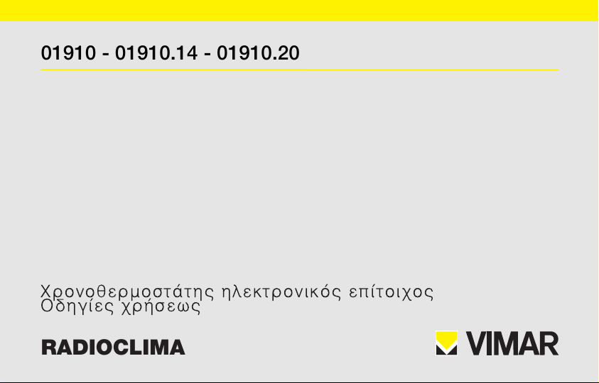
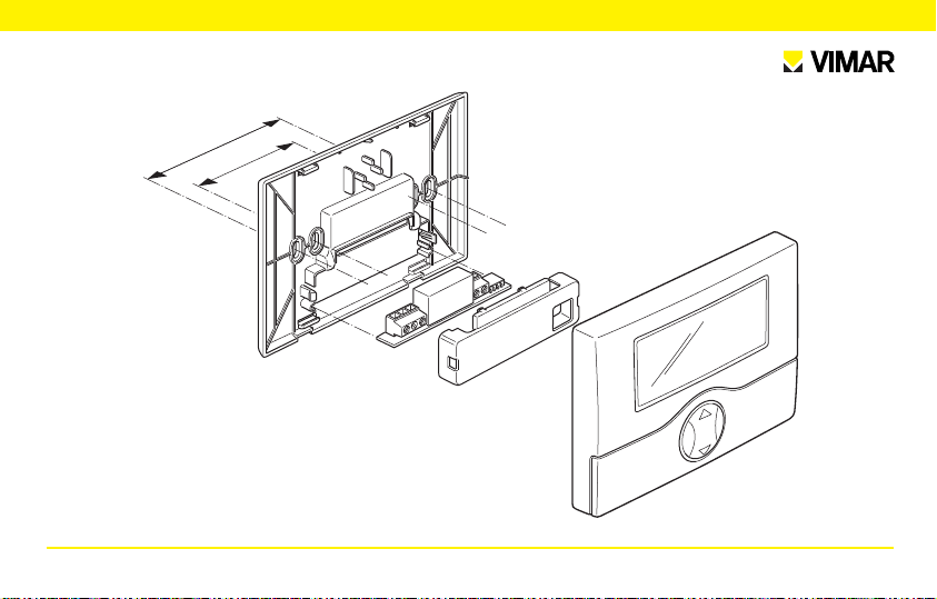
3. INSTALLAZIONE.
L’apparecchio deve essere installato a parete a un’altezza di 1,5 m
dal piano di calpestio, in una posizione idonea alla corretta rilevazione della temperatura ambiente, evitando l’installazione in nicchie,
dietro porte e tende o zone influenzate da fonti di calore o fattori
atmosferici.
La base dell’apparecchio è predisposta con 4 asole per il fissaggio
diretto alla parete con viti e tasselli ø 6 mm (non forniti), oppure per
l’installazione su scatole da incasso con fissaggio a viti con interasse 60 mm o 83,5 mm (scatole rettangolari unificate 3 moduli).
Va utilizzato in luoghi asciutti e non polverosi a temperatura compresa tra 0 °C e +40 °C.
Page 6
83,5 mm
60 mm
ITALIANO - 3
Page 7
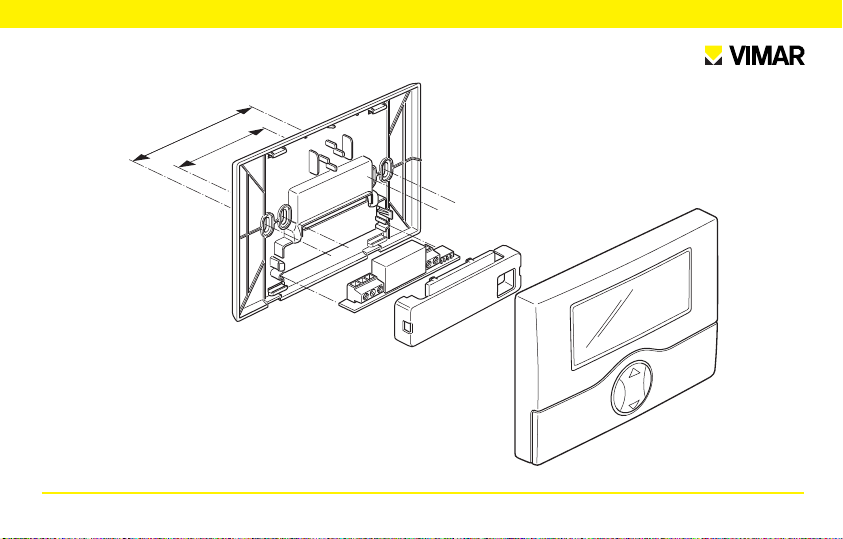
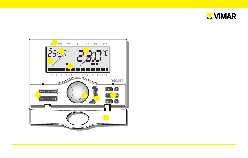
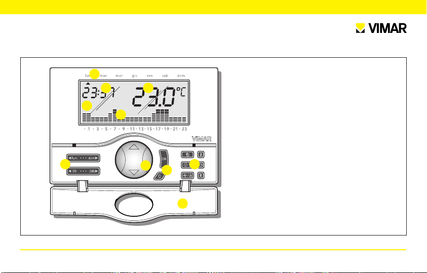
4. VISTA FRONTALE, COMANDI E DISPLAY.
1
3
2
4
5
6
7 7
7
8
4 - ITALIANO
1. Giorni della settimana.
2. Display.
3. Ora corrente.
4. Temperatura ambiente.
5. Andamento giornaliero del programma in esecuzione.
6. Tasto “mouse” per il comando delle funzioni base.
7. Tasti per la programmazione delle funzioni.
8. Coperchio frontale ribaltabile.
Page 8
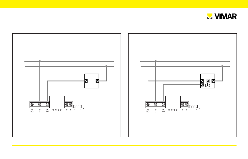
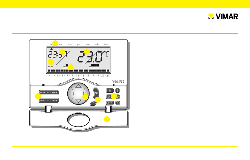
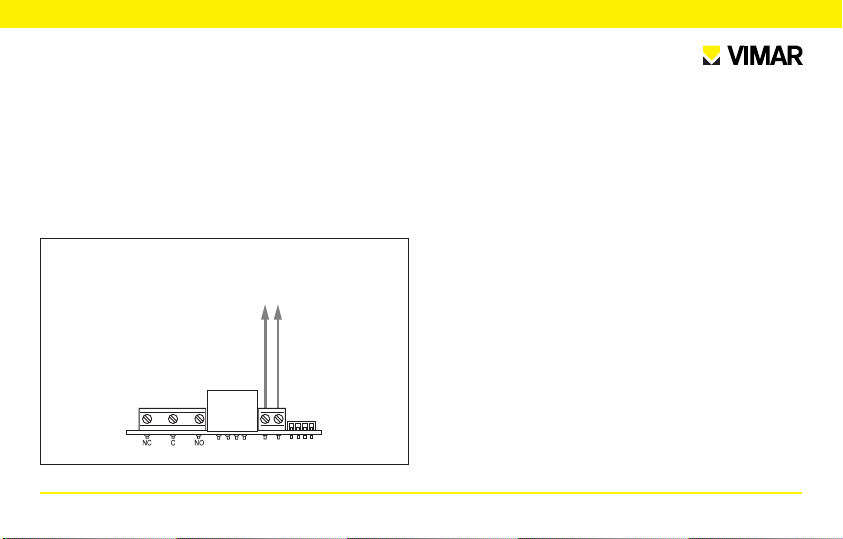
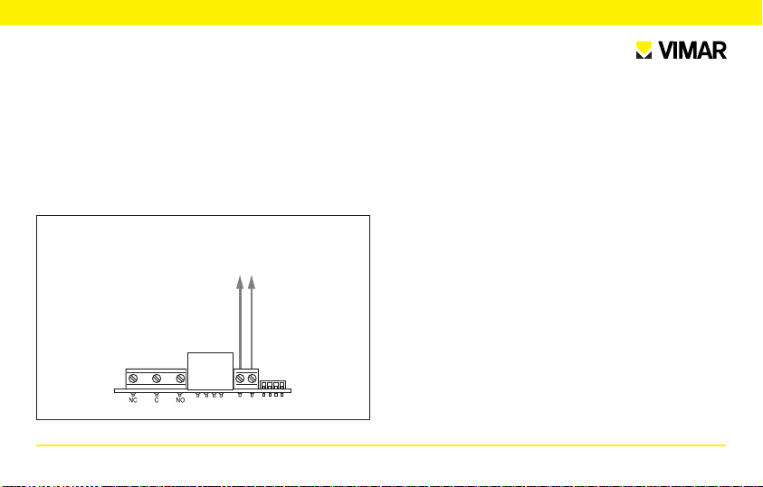
5. COLLEGAMENTI.
L
N
U1
Pompe di circolazione, bruciatori, elettrovalvole.
Valvole motorizzate.
L
N
CHIUDE
APRE
U1
ITALIANO - 5
Page 9
Comando tramite attuatore telefonico.
Collegamento con
attuatore telefonico
con contatto pulito
Mediante un attuatore telefonico collegato ai morsetti dedicati (simbolo telefonico), è possibile attivare il termostato a distanza.
Se il cronotermostato si trova nello stato di antigelo, spento o
spento a tempo, chiudendo il contatto verrà ripristinato il funzionamento automatico. Perché avvenga la commutazione, il contatto
deve rimanere chiuso per almeno 10 s.
6 - ITALIANO
Page 10
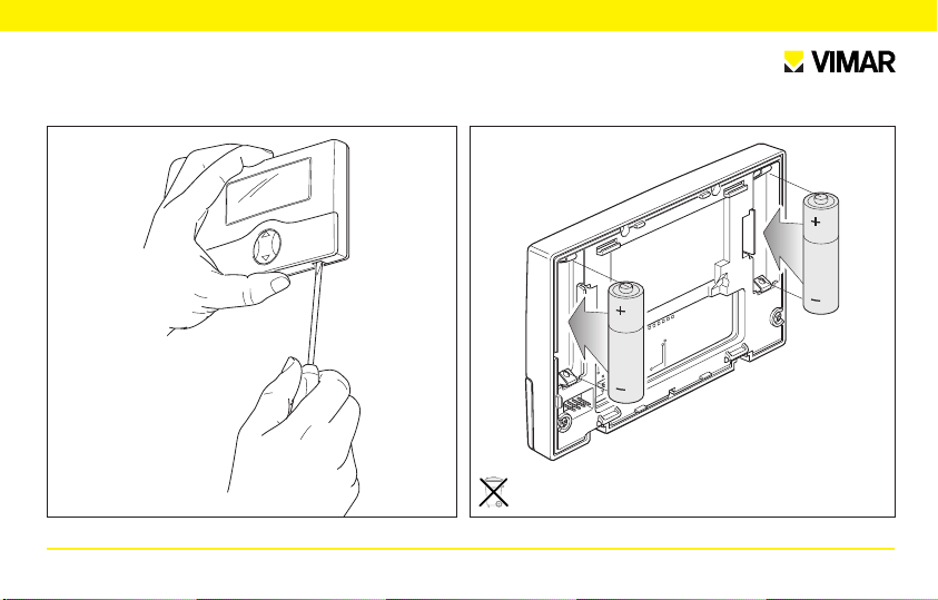
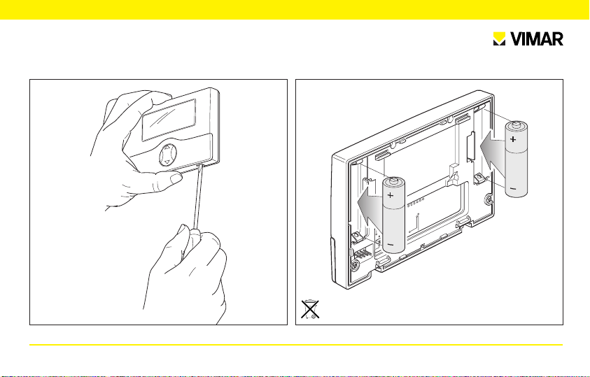
Inserimento/Sostituzione batterie di alimentazione.
AA LR6 1,5 V
ATTENZIONE!
In caso di sostituzione, smaltire le batterie
negli appositi cassonetti per la raccolta differenziata.
1.
2.
ITALIANO - 7
Page 11
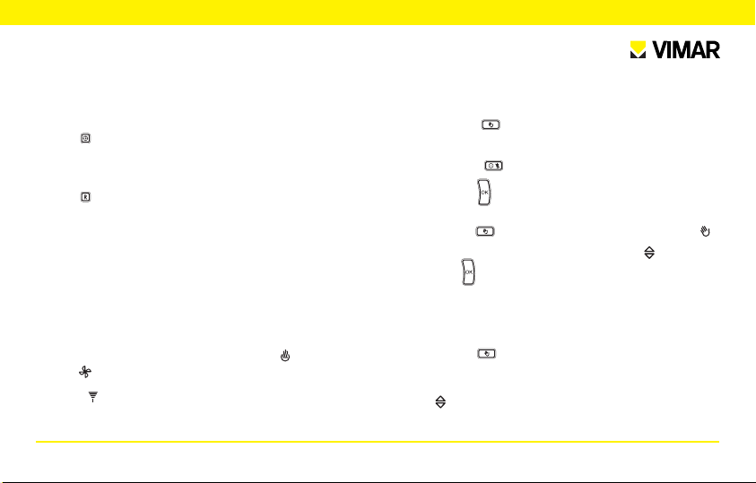
6. FUNZIONI DEI TASTI.
• Tasti .
Consentono di entrare nella funzione “Programmazione” e di
selezionare il giorno da programmare e di eseguire la copia del
programma.
• Tasti .
Consentono di entrare nella funzione “Programmazione” e di
selezionare l’ora da programmare.
• Tasto .
Modifica dei parametri selezionati (es. incremento/decremento
della temperatura).
• Tasto .
Conferma delle impostazioni.
• Tasto .
Cancellazione o ritorno alla videata precedente.
• Tasto .
A cronotermostato acceso, consente di selezionare il funzionamento manuale o automatico. A cronotermostato spento, pre-
8 - ITALIANO
mendo una volta, consente di accenderlo in modalità manuale,
premendo due volte, di accenderlo in modalità automatico.
• Tasto .
Premuto in sequenza, imposta le funzioni di: “Spento”, “Spento
a tempo”, “Antigelo” (impostabile solo in riscaldamento).
- SPENTO.
Consente di spegnere il cronotermostato, confermare con il tasto .
Il display visualizza ora e temperatura, il relè di uscita rimane
nello stato di OFF.
- ANTIGELO.
Impostabile solo in riscaldamento, consente di impostare un livello minimo di temperatura tale da evitare il danneggiamento delle
condutture o per non far scendere la temperatura al di sotto di un
livello di sicurezza.
Impostare la temperatura di antigelo con il tasto , confermare
con il tasto .
- SPENTO A TEMPO.
Consente di spegnere il cronotermostato per un periodo a piacere, impostabile fino a 99 ore. Impostare il tempo di spegnimento
Page 12
con il tasto , confermare con il tasto .
• Tasto .
Mantenendo premuto a lungo il pulsante, consente di selezionare la
modalità di funzionamento del cronotermostato, scegliendo tra
“Riscaldamento” o “Condizionamento”. Quando il simbolo o il
simbolo lampeggia, utilizzare il tasto , per selezionare la modalità di fornitura.
Confermare il tasto .
• Tasto .
Premuto in sequenza, consente di impostare i valori della
“Temperatura di antigelo”, dei “Livelli di temperatura T1-T2T3”, del “Differenziale termico”, della “Scala di temperatura”.
Impostare i singoli livelli con il tasto .
Confermare con il tasto .
- ANTIGELO.
Impostabile solo in riscaldamento, consente di impostare un livello minimo di temperatura tale da evitare il danneggiamento delle
condutture o per non far scendere la temperatura al di sotto di un
livello di sicurezza.
- LIVELLI DI TEMPERATURA.
Consente di visualizzare e/o modificare il valore dei livelli di temperatura T1-T2-T3 sia per il programma di riscaldamento che di condizionamento.
- DIFFERENZIALE TERMICO.
Consente di impostare il valore del differenziale termico. Per diffe-
renziale termico si intende la differenza tra il valore di temperatura impostato e l’effettiva temperatura di accensione o di spegnimento dell’impianto. Adeguando il differenziale termico al tipo di
impianto se ne evitano continue accensioni e spegnimenti; impianti ad alta inerzia (ad esempio impianti con radiatori in ghisa) necessitano di un valore basso di differenziale termico, mentre impianti
a bassa inerzia (ad esempio ventil-convettori) necessitano di un
valore più alto.
Esempio.
Impostando la temperatura ambiente a 20 °C e il differenziale termico a 0,3 °C, l’impianto si accenderà quando la temperatura
ambiente scenderà a 19,7 °C e si spegnerà quando raggiungerà i
20,3 °C.
ITALIANO - 9
Page 13
- SCALA DI TEMPERATURA.
Consente di impostare l’unità di misura della temperatura, scegliendo tra gradi Celsius e gradi Fahrenheit.
• Tasto .
Consente di regolare il giorno della settimana e l’ora corrente. In programmazione consente di selezionare l’orario a passi di 15 minuti.
• Tasto .
Premuto a lungo, tutti i parametri impostati si portano nelle condizioni di prima accensione (azzeramento dell’orologio, cancellazione dei programmi utente, ritorno ai valori di default per i 3 livelli di
temperatura).
7 FUNZIONAMENTO.
Effettuare i collegamenti elettrici, installare l’apparecchio, quindi inserire le batterie.
Se il relè è attivato, viene visualizzato il simbolo in inverno o il
simbolo in estate.
Il simbolo indica la presenza del modulo TX radio o la mancanza
del modulo relè. Attendere 2 minuti max per il riconoscimento auto-
10 - ITALIANO
matico oppure eseguire l’operazione di reset.
• ACCENSIONE.
Premere il tasto e selezionare il funzionamento desiderato.
• SPEGNIMENTO.
Premere il tasto , selezionare la modalità desiderata, quindi
premere il tasto .
• FUNZIONAMENTO IN MODALITA’ MANUALE.
Premere il tasto finché non compare sul display il simbolo .
Selezionare la temperatura desiderata con il tasto , quindi pre-
mere il tasto .
Eventualmemte attendere 5 secondi perché l’operazione venga
confermata.
• FUNZIONAMENTO IN MODALITA’ AUTOMATICO.
Premere il tasto finché non compare sul display l’andamento
giornaliero del programma. E’ possibile passare in modalità
manuale temporanea selezionando la temperatura desiderata con
il tasto quindi attendere 5 secondi perchè l’operazione venga
confermata. La nuova impostazione resterà attiva fino al successi-
Page 14
vo cambio di livello di temperatura impostato, dopo di che verrà
ripristinato il programma memorizzato. Per tornare immediatamente in modalità automatico, premere il tasto .
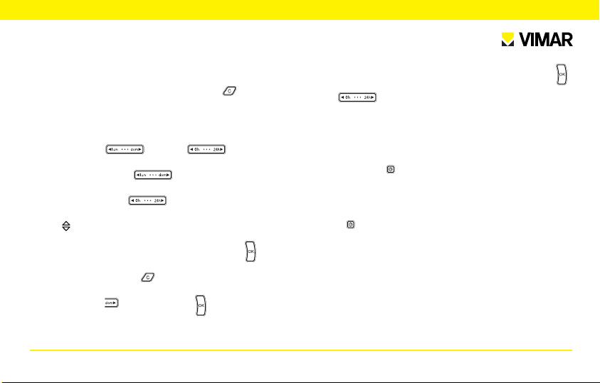
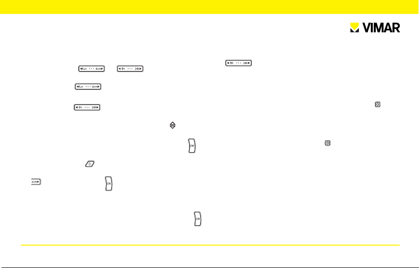
8 PROGRAMMAZIONE.
• Impostare i livelli di temperatura T1-T2-T3.
• Premere i tasti o i tasti per entrare nel
menù programmazione.
• Selezionare con i tasti il giorno da programmare (si
consiglia di cominciare da lunedì).
• Selezionare con i tasti l’ora da modificare.
• Impostare il livello di temperatura desiderata scegliendo con il
tasto tra Antigelo e Livelli di temperatura T1-T2-T3.
1. Terminata l’impostazione del giorno, premere il tasto per con-
fermare.
Premendo 2 volte il tasto si ritorna al funzionamento normale.
2. Se si desidera proseguire con la programmazione di altri giorni,
premere il tasto al posto del tasto .
Il cronotermostato salva i dati impostati, il menù visualizza il giorno successivo e appare la scritta “Copy”.
Per copiare il programma del giorno precedente premere il tasto ,
altrimenti posizionarsi sull’ora desiderata con i
tasti e modificare il programma a piacimento.
Ripetere il punto 1. o il punto 2. per programmare tutti i giorni
della settimana.
Se si desidera impostare l’ora di attivazione del livello di temperatura regolata ai 15 minuti, 30 minuti o 45 minuti, premere in
sequenza il tasto .
Esempio.
Desiderando che il programma passi dal livello T1 al livello T2 alle
6:30, impostare il livello T2 alle ore 6:00, quindi premere due volte
il tasto , quindi proseguire normalmente.
ITALIANO - 11
Page 15

9. PRINCIPALI CARATTERISTICHE.
• Alimentazione: 3 V d.c. mediante 2 batterie stilo AA LR6 1,5 V (non
fornite)
• Durata della batteria: superiore ad un anno
• Uscita: a relè con contatto pulito in scambio 5(2) A 250 V~
• Tipo di regolazione: ON/OFF
• Possibilità di collegamento in radiofrequenza ad attuatori 01923 e
01924 previa sostituzione del modulo relè con il modulo trasmettitore 01921 (ulteriori informazioni sul catalogo generale)
• Aggiornamento della temperatura visualizzata: ogni 20 s
• Visualizzazione temperatura ambiente: 0 °C +40 °C
• Risoluzione della lettura: 0,1 °C
• Risoluzione delle impostazioni: 0,1 °C
• Precisione della lettura:
- ≤ ±0,5 °C tra +15 °C e +30 °C
- ≤ ±0,8 °C agli estremi
• Differenziale termico: regolabile da 0,1 °C a 1 °C
• Campo di regolazione:
- +4 °C - +15 °C in antigelo
- +5 °C - +35 °C in riscaldamento o condizionamento
• Errore orologio: ≤ ±1 s al giorno
12 - ITALIANO
• Funzioni principali:
- impostazione oraria della temperatura con passi da 15 minuti
- 3 livelli di temperatura programmabili per riscaldamento + 3 livelli
di temperatura per condizionamento + 1 livello antigelo
- programmazione settimanale
- 1 programma automatico impostabile dall’utente (sia per riscaldamento che per condizionamento)
- possibilità di forzare il programma variando manualmente la temperatura
- regolazione per riscaldamento e condizionamento
- funzione antigelo
- possibilità di spegnimento temporizzato
- possibilità di attivazione tramite attuatore telefonico
- possibilità di visualizzazione in gradi Celsius o Fahrenheit
- reset del dispositivo
• Grado di protezione: IP30
• Apparecchio di classe II:
• Numero di cicli manuali: 3.000
• Numero di cicli automatici: 100.000
• Tipo di apertura dei contatti: microdisconnessione
Page 16

• Tipo di azione: 1BU
• Indice di tracking: PTI175
• Situazione di polluzione: normale
• Temperatura ambiente durante il trasporto: -25 °C +60 °C
• Temperatura di funzionamento: 0 °C +40 °C.
• Classe del software: A
10. REGOLE DI INSTALLAZIONE.
L’installazione deve essere effettuata con l’osservanza delle disposi-
zioni regolanti l’installazione del materiale elettrico in vigore nel paese
dove i prodotti sono installati.
11. CONFORMITÀ NORMATIVA.
Direttiva BT
Direttiva EMC
Norme EN 60730-1, EN 60730-2-7, EN 60730-2-9
ITALIANO - 13
Page 17

CAUTION!
When the symbol flashes, the batteries are dying.
REPLACE THEM AS SOON AS POSSIBLE!
When the symbol is lit, the output relay automatically switches OFF.
REPLACE THE BATTERIES!
Programs and settings are not erased when the batteries are low or when changing them.
After replacing the batteries, the time and day of the week must be reset.
Page 18

CONTENTS.
1. Description . . . . . . . . . . . . . . . . . . . . . . . . . . . . . . . . . . . . . . . . . . . . . . . . . . . . . . . . . . . . . . . . . . . . . . . . . . . . . . . . . . . . . . . . . . . . 16
2. Scope . . . . . . . . . . . . . . . . . . . . . . . . . . . . . . . . . . . . . . . . . . . . . . . . . . . . . . . . . . . . . . . . . . . . . . . . . . . . . . . . . . . . . . . . . . . . . . . 16
3. Installation . . . . . . . . . . . . . . . . . . . . . . . . . . . . . . . . . . . . . . . . . . . . . . . . . . . . . . . . . . . . . . . . . . . . . . . . . . . . . . . . . . . . . . . . . . . . 16
4. Front view and view of controls . . . . . . . . . . . . . . . . . . . . . . . . . . . . . . . . . . . . . . . . . . . . . . . . . . . . . . . . . . . . . . . . . . . . . . . . . . . . 18
5. Connections
Circulation pumps, burners, solenoid valves . . . . . . . . . . . . . . . . . . . . . . . . . . . . . . . . . . . . . . . . . . . . . . . . . . . . . . . . . . . . . . . 19
Motor-operated valves . . . . . . . . . . . . . . . . . . . . . . . . . . . . . . . . . . . . . . . . . . . . . . . . . . . . . . . . . . . . . . . . . . . . . . . . . . . . . . . 19
Remote telephone actuator . . . . . . . . . . . . . . . . . . . . . . . . . . . . . . . . . . . . . . . . . . . . . . . . . . . . . . . . . . . . . . . . . . . . . . . . . . . 20
Fitting/Replacing the main batteries . . . . . . . . . . . . . . . . . . . . . . . . . . . . . . . . . . . . . . . . . . . . . . . . . . . . . . . . . . . . . . . . . . . . . 21
6. Functions of the buttons . . . . . . . . . . . . . . . . . . . . . . . . . . . . . . . . . . . . . . . . . . . . . . . . . . . . . . . . . . . . . . . . . . . . . . . . . . . . . . . . . 22
7. Operation . . . . . . . . . . . . . . . . . . . . . . . . . . . . . . . . . . . . . . . . . . . . . . . . . . . . . . . . . . . . . . . . . . . . . . . . . . . . . . . . . . . . . . . . . . . . . 24
8. Programming . . . . . . . . . . . . . . . . . . . . . . . . . . . . . . . . . . . . . . . . . . . . . . . . . . . . . . . . . . . . . . . . . . . . . . . . . . . . . . . . . . . . . . . . . . 25
9. Characteristics . . . . . . . . . . . . . . . . . . . . . . . . . . . . . . . . . . . . . . . . . . . . . . . . . . . . . . . . . . . . . . . . . . . . . . . . . . . . . . . . . . . . . . . . . 26
10. Installation rules . . . . . . . . . . . . . . . . . . . . . . . . . . . . . . . . . . . . . . . . . . . . . . . . . . . . . . . . . . . . . . . . . . . . . . . . . . . . . . . . . . . . . . . . 27
11. Conformity to standards . . . . . . . . . . . . . . . . . . . . . . . . . . . . . . . . . . . . . . . . . . . . . . . . . . . . . . . . . . . . . . . . . . . . . . . . . . . . . . . . . . 27
ENGLISH - 15
Page 19

1. DESCRIPTION.
Surface-mounted electronic chronothermostat to control ambient
temperature (heating and air-conditioning), daily/weekly programming, powered by two AA batteries LR6 1.5 V (not included), exchange relay output 5(2) A 250 V~
2. SCOPE.
The chronothermostat is suitable for ambient temperature control by
regulating the supply circuit of the burner or heat pump (heating), or
the supply circuit of the air conditioner (air conditioning), to maintain
ideal temperature conditions seven days a week.
The large display shows the ambient temperature, day, time, the operating status of the system and the daily temperature profile set for
the current program.
16 - ENGLISH
3. INSTALLATION.
The device must be surface-mounted at a height of 1.5 m from floor
level, in a position suitable for correctly measuring the ambient temperature. Do not install in niches, behind doors and curtains, or in areas affected by heat sources or outdoor weather.
The base of the device has 4 slots for fastening directly to the wall
with ø 6 mm screws and studs (not included), or for installation in inset boxes with screws placed 60 mm or 83.5 mm apart (standard 3module rectangular boxes).
Use in dry, non-dusty environments at a temperature between 0 °C
and +40 °C.
Page 20
83,5 mm
60 mm
ENGLISH - 17
Page 21
4. FRONT VIEW AND VIEW OF CONTROLS
1
3
2
4
5
6
7 7
7
8
.
18 - ENGLISH
1. Days of the week:
- lun = Monday
- mar = Tuesday
- mer = Wednesday
- gio = Thursday
- ven = Friday
- sab = Saturday
- dom = Sunday
2. Display.
3. Current time.
4. Ambient temperature.
5. Daily profile for the currently active program.
6. “Mouse” button to control the basic functions.
7. Function setting buttons.
8. Flipping front cover.
Page 22

5. CONNECTIONS.
L
N
U1
Circulation pumps, burners, solenoid valves.
Motor-operated valves.
L
N
CLOSE
OPEN
U1
ENGLISH - 19
Page 23
Remote telephone actuator.
Connection to a
telephone actuator
with clean contact
The chronothermostat may be remotely activated through a telephone actuator connected in series to the dedicated terminals (telephone symbol).
If the chronothermostat is in antifreeze status, off or off on timer,
closing the contact will restore the automatic mode. In order for the
switch to be made, the contact must remain closed for at least 10 s.
20 - ENGLISH
Page 24
Fitting/Replacing power batteries.
AA LR6 1,5 V
ATTENTION!
After replacing the battery, dispose of the old battery
in the appropriate sorted refuse bins.
1.
2.
ENGLISH - 21
Page 25

6. FUNCTIONS OF THE BUTTONS.
• Buttons .
Make it possible to enter the “Programming” function and select
the day to be programmed, and to copy the program.
• Buttons .
Make it possible to enter the “Programming” function and select
the time to be programmed.
• Button .
Edit the selected parameters (i.e. temperature increase/decrease).
• Button .
Confirm the settings.
• Button .
Delete or return to the previous screen.
• Button .
When the chronothermostat is on, selects manual or automatic
mode. When the chronothermostat is off, pressing once turns it on
in manual mode, pressing twice turns it on in automatic mode.
22 - ENGLISH
• Button .
Pressed in sequence, sets the functions: “Off”, “Off on timer”,
“Antifreeze” (available only in heating).
- OFF.
Makes it possible to shut off the chronothermostat, confirm with
the button .
The display shows time and temperature, the output relay remains
OFF.
- ANTIFREEZE.
Available only in heating, sets a minimum temperature level to
avoid damaging the wires, or to prevent the temperature from
falling below a given safety level. Set the temperature of antifreeze
using the button , confirm with the button .
- OFF ON TIMER.
Makes it possible to shut off the chronothermostat for a desired
time period, up to 99 hours. Set the shut-off time using the button , confirm with the button .
Page 26
• Button .
Holding down this button makes it possible to select the operating
mode of the chronothermostat, choosing between “Heating” or
“Air-conditioning”. When the symbol or symbol flashes,
use the button to select the mode.
Confirm with the button .
• Button .
Pressed in sequence, makes it possible to set the values for the
“Antifreeze temperature”, of the “Temperature levels T1-T2T3”, the “Hysteresis”, and “Temperature scale”.
Set the individual levels using the button .
Confirm with the button .
- ANTIFREEZE.
Available only in heating, sets a minimum temperature level to
avoid damaging the wires, or to prevent the temperature from
falling below a given safety level.
- TEMPERATURE LEVELS.
Displays and/or modifies the values of the temperature set-points
T1, T2, T3 for both heating and cooling programs.
- HYSTERESIS.
Adjusts the value of the temperature hysteresis parameter.
Hysteresis is the amount by which the ambient temperature can
deviate from the set-point before the system is switched on and
off. By adapting the hysteresis parameter to the type of system, it
is possible to prevent repeated switch-on and switch-off around
the set-point value; systems with high inertia (for example with cast
iron radiators) require a low hysteresis value, whereas systems with
low inertia (for example fan-convectors) require a higher value.
Example.
With a temperature set-point of 20 °C and a hysteresis of 0.3 °C,
the system will switch on when the ambient temperature drops below 19.7 °C, and will switch off when the ambient temperature
reaches 20.3 °C.
- TEMPERATURE SCALE.
Used for setting the units of measurement for temperature, choosing between degrees Celsius and degrees Fahrenheit.
• Button .
Sets the current day of the week and time. In programming, it is
used to set the time in 15-minute increments.
ENGLISH - 23
Page 27
• Button .
When this button is held down, all parameters set return to their
original default status (clock reset, user programs deleted, return
to default values for the 3 temperature levels).
7 OPERATION.
Complete the electrical connections, install the device, then insert
the batteries.
If the relay is activated, the symbol appears in winter or the symbol in summer.
The symbol indicates that the TX radio module is present or the
relay module is missing. Wait no more than 2 minutes for automatic
recognition, or reset the device.
• SWITCHING ON.
Press the button and select the desired operation.
• SHUTDOWN.
Press the button , select the desired mode, then press the button .
24 - ENGLISH
• OPERATION IN MANUAL MODE.
• OPERATION IN AUTOMATIC MODE.
Press the button until the symbol appears on the display.
Select the desired temperature using the button , then press
the button .
If necessary, wait 5 seconds for the operation to be confirmed.
Press the button until the daily programming pattern appears
on the display. It is possible to switch temporarily to manual mode
by selecting the desired temperature with the button then wait
5 seconds for the operation to be confirmed. The new setting will
remain in effect until the next time the temperature setting is
changed, after which the saved program will be restored. For return immediately to automatic mode, press the button .
Page 28
8 PROGRAMMING.
• Set the temperature levels T1-T2-T3.
• Press the buttons or to enter the program-
ming menu.
• Use the buttons to select the day to be programmed
(we recommend starting on Monday).
• Use the buttons to select the time to be modified.
• Set the desired temperature level by using the button to choose
between Antifreeze and Temperature levels T1-T2-T3.
1. When you have finished setting the day, press the button to
confirm.
Pressing the button twice returns to normal operating mode.
2. If you wish to continue programming other days, press the button
instead of the button .
The chronothermostat saves the set data, the menu displays the
next day and the message “Copy” appears.
To copy the program of the previous day, press the button ,
otherwise move to the desired time using the buttons
and edit the program as you prefer.
Repeat point 1. and point 2. to program all of the days of the
week.
If you wish to set the activation time of the temperature level at 15
minutes, 30 minutes or 45 minutes, press the button in sequence.
Example.
If you want the program to change from level T1 to level T2 at 6:30,
set level T2 at 6:00, press the button , then continue normally.
ENGLISH - 25
Page 29

9. CHARACTERISTICS.
• Supply voltage: 3 V d.c. with 2 AA LR6 1,5 V batteries (not included)
• Batteries life: up to 1 year
• Output: 5(2) A 250 V~ change-over relay output
• Type of regulation: ON/OFF
• It is possible to create a radio link with actuators 01923 and 01924
by replacing the relay module with the transmitter module 01921
(more information in the general catalogue)
• Updating of display temperature: every 20 s
• Ambient temperature display range: 0 °C +40 °C
• Resolution of the reading: 0,1 °C
• Resolution of the settings: 0,1 °C
• Precision of the reading:
- ≤ ±0,5 °C between +15 °C and +30 °C
- ≤ ±0,8 °C at the temperature extremes
• Hysteresis: adjustable between 0,1 °C and 1 °C
• Thermostat operating range:
- +4 °C - +15 °C in antifreeze mode
- +5 °C - +35 °C in heating or cooling mode
• Clock accuracy: ≤ ±1 s a day
26 - ENGLISH
• Principal functions:
- hourly temperature settings in 15-minute steps
- 3 programmable temperature set-points for heating + 3 temperature set-points for cooling + 1 antifreeze level
- weekly programming
- 1 automatic program that may be set by the user (for both heating
and air-conditioning)
- possibility of forcing the program by manually adjusting the temperature
- regulation for both heating and cooling systems
- antifreeze function
- possibility of timed switch off
- remote activation option via telephone dialler
- select between display in degrees Celsius and Fahrenheit
- device reset
• Protection degree: IP30
• Class II equipment:
• Number of manual cycles: 3.000
• Number of automatic cycles: 100.000
Page 30

• Type of contact opening: micro-disconnect
• Type of action: 1BU
• Tracking index: PTI175
• Pollution status: normal
• Ambient temperature range during transport: -25 °C +60 °C
• Operating temperature: 0 °C +40 °C
• Software class: A
10. INSTALLATION RULES.
The installation must be done according to rules for electrical installations of buildings in force in the country where the products are installed.
11. CONFORMITY TO STANDARDS.
LV Directive
EMC Directive
Standards EN 60730-1, EN 60730-2-7, EN 60730-2-9
ENGLISH - 27
Page 31

ATTENTION !
Quand le symbole clignote, les batteries d’alimentation sont proches de l’usure.
REMPLACER LES BATTERIES DES QUE POSSIBLE !
Quand le symbole est allumé, le relais de sortie passe automatiquement sur OFF.
REMPLACER LES BATTERIES!
Les batteries usées et leur remplacement ne provoquent pas l’effacement ou l’annulation des programmes et des réglages. Après avoir procédé au remplacement des batteries, l’heure et le jour de la semaine devront être à nouveau réglés.
Page 32

TABLES DES MATIERES.
1. Description . . . . . . . . . . . . . . . . . . . . . . . . . . . . . . . . . . . . . . . . . . . . . . . . . . . . . . . . . . . . . . . . . . . . . . . . . . . . . . . . . . . . . . . . . . . . 30
2. Domaine d’application . . . . . . . . . . . . . . . . . . . . . . . . . . . . . . . . . . . . . . . . . . . . . . . . . . . . . . . . . . . . . . . . . . . . . . . . . . . . . . . . . . . 30
3. Installation . . . . . . . . . . . . . . . . . . . . . . . . . . . . . . . . . . . . . . . . . . . . . . . . . . . . . . . . . . . . . . . . . . . . . . . . . . . . . . . . . . . . . . . . . . . . 30
4. Vue frontale, vue commandes et display . . . . . . . . . . . . . . . . . . . . . . . . . . . . . . . . . . . . . . . . . . . . . . . . . . . . . . . . . . . . . . . . . . . . . 32
5. Connexions
Pompes de circulation, brûleurs, électrovannes . . . . . . . . . . . . . . . . . . . . . . . . . . . . . . . . . . . . . . . . . . . . . . . . . . . . . . . . . . . . . . . .33
Vannes motorisées . . . . . . . . . . . . . . . . . . . . . . . . . . . . . . . . . . . . . . . . . . . . . . . . . . . . . . . . . . . . . . . . . . . . . . . . . . . . . . . . . . . . . 33
Commande par actuateur téléphonique . . . . . . . . . . . . . . . . . . . . . . . . . . . . . . . . . . . . . . . . . . . . . . . . . . . . . . . . . . . . . . . . . . . . . 34
Introduction/Remplacement batteries alimentation . . . . . . . . . . . . . . . . . . . . . . . . . . . . . . . . . . . . . . . . . . . . . . . . . . . . . . . . . . . . . 35
6. Fonctions des touches . . . . . . . . . . . . . . . . . . . . . . . . . . . . . . . . . . . . . . . . . . . . . . . . . . . . . . . . . . . . . . . . . . . . . . . . . . . . . . . . . . . 36
7. Fonctionnement . . . . . . . . . . . . . . . . . . . . . . . . . . . . . . . . . . . . . . . . . . . . . . . . . . . . . . . . . . . . . . . . . . . . . . . . . . . . . . . . . . . . . . . . 38
8. Programmation . . . . . . . . . . . . . . . . . . . . . . . . . . . . . . . . . . . . . . . . . . . . . . . . . . . . . . . . . . . . . . . . . . . . . . . . . . . . . . . . . . . . . . . . 39
9. Caractéristiques techniques . . . . . . . . . . . . . . . . . . . . . . . . . . . . . . . . . . . . . . . . . . . . . . . . . . . . . . . . . . . . . . . . . . . . . . . . . . . . . . . 40
10. Règles d’installation . . . . . . . . . . . . . . . . . . . . . . . . . . . . . . . . . . . . . . . . . . . . . . . . . . . . . . . . . . . . . . . . . . . . . . . . . . . . . . . . . . . . . 41
11. Conformité aux Normes . . . . . . . . . . . . . . . . . . . . . . . . . . . . . . . . . . . . . . . . . . . . . . . . . . . . . . . . . . . . . . . . . . . . . . . . . . . . . . . . . . 41
FRANÇAIS - 29
Page 33

1. DESCRIPTION.
Chronothermostat électronique en saillie de contrôle de la tempé-
rature ambiante (chauffage et climatisation), programmation quotidienne/hebdomadaire, alimentation avec deux piles alcalines AA
LR6 1,5 V (non fournies), sortie par relais avec contact inverseur
5(2) A 250 V~
2. DOMAINE D’APPLICATION.
Cet appareil est en mesure de contrôler la température ambiante en
agissant sur le circuit d'alimentation du brûleur ou du circulateur
(chauffage), ou sur le circuit d'alimentation du climatiseur (climatisation), en garantissant une situation de température idéale, chaque
jour, pendant toute la semaine.
L’affichage de larges dimensions visualise la température ambiante,
le jour, l’heure, l’état de fonctionnement de l’installation et le profil de
température quotidien réglé pour le programme en cours d’exécution.
30 - FRANÇAIS
3. INSTALLATION.
L’appareil doit être installé en saillie à une hauteur de 1,5 m du plan
de piétinement, dans une position permettant le relevé correct de la
température ambiante, en évitant son installation dans des niches,
derrière des portes, des rideaux ou des tentures ou encore dans des
zones exposées à l’influence de sources de chaleur ou de facteurs
atmosphériques.
La base de l’appareil est dotée de 4 oeillets de fixation directe à la
paroi murale, avec vis et chevilles ø 6 mm (non fournies), ou bien
pour permettre une installation sur boîte d’encastrement avec fixation au moyen de vis avec interaxe 60 mm ou 83,5 mm (boîtes rectangulaires unifiées à 3 modules).
L’appareil devra être utilisé en lieu sec et sans poussière, à une tem-
pérature comprise entre 0 °C et +40 °C.
Page 34

83,5 mm
60 mm
FRANÇAIS - 31
Page 35

4. VUE FRONTALE, VUE COMMANDES ET DISPLAY.
1
3
2
4
5
6
7 7
7
8
32 - FRANÇAIS
1. Jours de la semaine:
- lun = Lundi
- mar = Mardi
- mer = Mercredi
- gio = Jeudi
- ven = Vendredi
- sab = Samedi
- dom = Dimanche
2. Display.
3. Heure actuelle.
4. Température ambiante.
5. Situation quotidienne du programme en cours d’exécution.
6. Touche “mouse” pour commander les fonctions de base.
7. Touches pour le réglage de la fonction.
8. Couvercle frontal relevable.
Page 36

5. CONNEXIONS.
L
N
U1
Pompes de circulation, brûleurs, électrovannes.
Vannes motorisées.
L
N
FERME
OUVERT
U1
FRANÇAIS - 33
Page 37

Commande par actuateur téléphonique.
Connexion avec
actuateur téléphonique
avec contact vierge
Le thermostat a distance peut être activé au moyen d’un actuateur
téléphonique connecté aux bornes spécifiques (symbole du téléphone). Si le chronothermostat se trouve sur la position horsgel,
coupure ou coupure temporisée, en fermant le contact le programme automatique sera réactivé. Pour permettre la commuta-
tion, le contact doit rester fermé pendant 10 secondes.
34 - FRANÇAIS
Page 38

Introduction/Remplacement batteries alimentation.
AA LR6 1,5 V
ATTENTION !
En cas de remplacement, les batteries usées
devront être jetées dans des poubelles ou
des conteneurs spéciaux de collecte sélective.
1.
2.
FRANÇAIS - 35
Page 39

6. FONCTIONS DES TOUCHES.
• Touches .
Permet d’accéder à la fonction “Programmation”, de sélection-
ner le jour à programmer et de faire une copie du programme.
• Touches .
Permettent d’entrer dans la fonction “Programmation” et de sé-
lectionner l’heure à programmer.
• Touche .
Modification des paramètres sélectionnés (ex. augmentation /diminution de la température).
• Touche .
Confirmation des réglages.
• Touche .
Annulation et retour à la page-écran précédente.
• Touche .
Lorsque le chronothermostat est allumé, permet la sélection du
fonctionnement en manuel ou en automatique. Lorsque le chronothermostat est éteint, avec une seule pression permet son alluma-
36 - FRANÇAIS
ge en mode manuel, avec deux pressions permet son allumage en
mode automatique.
• Touche .
Pressé en séquence, règle les fonctions de : “Eteint”, “Eteint
avec retard”, “Hors gel” (réglage possible uniquement en moda-
lité de chauffage).
- ETIENT.
Permet l’extinction du chronothermostat, confirmer avec la touche .
L’affichage visualise l’heure et la température, le relais de sor-
tie reste sur OFF.
- HORS GEL.
Réglage possible uniquement en modalité de chauffage, permet le
réglage d’un niveau minimum de température afin d’éviter tout
endommagement des canalisations et d’interdire à la température
de descendre sous le niveau de sécurité.
Régler la température hors gel à l’aide de la touche , valider
avec la touche .
- ETEINT AVEC RETARD.
Permet l’extinction du chronosthermostat pendant le temps dési-
Page 40

ré, jusqu’à un maximum de 99 heures. Régler le délai d’extinction
avec la touche , confirmer avec la touche .
• Touche .
En gardant la touche longuement pressée, permet la sélection du
mode de fonctionnement du chronothermostat, en choisissant
“Chauffage” ou “Climatisation”. Quand le symbole ou le
symbole clignote, utiliser la touche , pour sélectionner le
mode de fourniture.
Valider avec la touche .
• Touche .
En pressant en séquence, permet le réglage des valeurs de la
“Hors gel”, des “Niveaux de temperature T1-T2-T3”, de l’
“Hysteresis”, de la “Plage de temperature”.
Régler chaque niveau à l’aide de la touche .
Valider avec la touche .
- HORS GEL.
Réglage possible uniquement en modalité de chauffage, permet
de régler un niveau minimum de température afin d’éviter tout
endommagement des canalisations et d’interdire à la température
de descendre sous le niveau de sécurité.
- NIVEAUX DE TEMPERATURE.
Permet de visualiser et/ou modifier la valeur des niveaux de température T1, T2, T3, non seulement pour les programmes de
chauffage mais aussi pour ceux de climatisation.
- HYSTERESIS.
Permet de régler la valeur de l’hystérésis.
L’hystérésis est la différence entre la valeur de température réglée
et la température réelle d’allumage et extinction de l’installation. En
adaptant l’hystérésis au type d’installation on en évite les allumages et les extinctions permanentes et répétées ; les installations
caractérisées par une forte inertie (par exemple les installations
avec des radiateurs en fonte) ont besoin d’une faible valeur d’hys-
térésis tandis que pour les installations avec une faible inertie (par
exemple les ventil-convecteurs une valeur haute est nécessaire.
Exemple.
En réglant la température ambiante sur 20 °C et l’hystérésis sur
0,3 °C, l’installation s’allumera quand la température ambiante arrivera à 19,7 °C et s’éteindra quand elle parviendra à 20,3 °C.
FRANÇAIS - 37
Page 41

- PLAGE DE TEMPERATURE.
Permet de régler l’unité de mesure de la température, en choisissant entre degrés Celsius et degrés Fahrenheit.
• Touche .
Permet le réglage du jour de la semaine et de l’heure présente. Lors
de la programmation permet de sélectionner l’horaire avec des intervalles de 15 minutes.
• Touche .
En pressant longuement, tous les paramètres réglés se mettent
dans les conditions identiques à celles du premier allumage (réinitialisation de l’horloge, effacement des programmes utilisateur, retour aux valeurs de défaut pour les 3 niveaux de température).
7 FONCTIONNEMENT.
Effectuer les connexions électriques, installer l’appareil, puis introduire les batteries.
Si le relais est actif, le symbole est visualisé en hiver ou le symbole en été.
38 - FRANÇAIS
Le symbole indique la présence du module TX radio ou l’absence du module de relais. Patienter 2 minutes au maximum pour permettre l’identification automatique ou bien effectuer l’opération de reset.
• ALLUMAGE.
Presser la touche et sélectionner le fonctionnement souhaité.
• EXTINCTION.
Presser la touche , sélectionner la modalité souhaitée, puis
presser la touche .
• FONCTIONNEMENT EN MODE MANUEL.
Presser la touche jusqu’à l’affichage du symbole .
Sélectionner la température souhaitée à l’aide de la touche ,
puis presser la touche .
Patienter éventuellement 5 secondes pour obtenir la confirmation
de l’opération.
• FONCTIONNEMENT EN MODE AUTOMATIQUE.
Presser la touche jusqu’à l’affichage de la situation journalière
Page 42

du programme. Il est possible de passer temporairement en mode
manuel en sélectionnant la température souhaitée à l’aide de la
touche puis patienter 5 secondes pour obtenir confirmation de
l’opération ; le programme sauvegardé sera ensuite rétabli.
Pour retourner immédiatement en mode automatique, presser la
touche .
8 PROGRAMMATION.
• Régler les niveaux de température T1-T2-T3.
• Presser les touches ou les touches pour
entrer dans le menu de programmation.
• A l’aide des touches sélectionner le jour à programmer
(il est recommandé de commencer par le lundi).
• SelSélectionner avec les touches l’heure à modifier.
• Régler le niveau de température souhaitée en sélectionnant à l’ai-
de de la touche entre Hors gel et Niveaux de température
T1-T2-T3.
1. Après le réglage du jour, presser la touche pour valider.
Presser 2 fois la touche on retourne en
fonctionnement normal.
2. Si l’on souhaite poursuivre avec la programmation d’autres jours,
presser la touche au lieu de la touche .
Le chronothermostat sauvegarde les données réglées, le menu
visualise le jour suivant et l’inscription “Copy” s’affiche.
Pour copier le programme du jour précédent, presser la touche ;
sinon, se positionner sur l’heure souhaitée avec les
touches et modifier à volonté le programme.
Répéter les deux derniers passages pour programmer tous les
jours de la semaine.
Pour régler l’heure d’activation du niveau de température réglé sur
15 minutes, 30 minutes ou 45 minutes, presser en séquence la
touche .
Exemple.
Si l’on souhaite que le programme passe du niveau T1 au niveau
T2 à 6h30, régler le niveau T2 sur 6h00, puis presser deux fois la
touche , puis continuer normalement.
FRANÇAIS - 39
Page 43

9. CARACTERISTIQUES TECHNIQUES.
• Alimentation : 3 V c.c. avec 2 piles alcalines AA LR6 1,5 V (non
fournies)
• Autonimie des batteries : au-dessus d’un an
• Sortie : relais inverseur 5(2) A 250 V~
• Type de réglage : ON/OFF
• Possibilité de connexion en radiofréquence avec actuateurs 01923
et 01924 après remplacement du module à relais par le module
émetteur 01921 (pour plus d’informations veuillez consulter le ca-
talogue général)
• Mise à jour température affichée : chaque 20 s
• Affichage température ambiante : de 0 °C à +40 °C
• Résolution de la lecture : 0,1 °C
• Résolution des programmations : 0,1 °C
• Précision de la lecture :
- ≤ ±0,5 °C entre +15 °C et +30 °C
- ≤ ±0,8 °C aux extrêmes
• Hystérésis : réglable de 0,1 °C à 1 °C
• Plage de réglage :
- +4 °C - +15 °C en horsgel
- +5 °C - +35 °C en chauffage ou climatisation
40 - FRANÇAIS
• Précision horloge : ≤ ±1 s par jour
• Fonctions principales :
-réglage horaire de la température par tranches de 15 minutes
- 3 niveaux de température programmables pour chauffage + 3 niveaux de température pour climatisation + 1 niveau hors gel
- programmation hebdomadaire
- 1 programme automatique réglable par l’utilisateur (pour le chauffage comme pour la climatisation)
- possibilité de forcer le programme en modifiant la température
-réglage pour chauffage et climatisation
- fonction horsgel
- possibilité d’extinction avec temporisation
- possibilité d’activation grâce au composeur téléphonique
-sélection entre visualisation en degrés Celsius et Fahrenheit
-réinitialisation du dispositif
• Degré de protection : IP30
• Appareil de classe II :
• Nombre de cycles manuels : 3.000
• Nombre de cycles automatiques : 100.000
• Type d’ouverture des contacts : microdéconnexion
Page 44

• Type d’action : 1BU
• Indice de tracking : PTI175
• Effets en matière de pollution : normaux
• Te mp érature ambiante pendant le transport : -25 °C +60 °C
• Te mp érature de fonctionnement : 0 °C +40 °C.
• Classe du logiciel: A
10. REGLES D’INSTALLATION.
L’installation doit être effectuée selon les normes pour les installa-
tions électriques des bâtiments en viguer dans le Pays oú les produits sont installés.
11. CONFORMITE AUX NORMES.
Directive BT
Directive EMC
Normes EN 60730-1, EN 60730-2-7, EN 60730-2-9
FRANÇAIS - 41
Page 45

ZU BEACHTEN!
Wenn die Ladung der Batterien zur Spannungsversorgung des Gerätes zu Ende geht,
blinkt das Zeichen auf.
IN DIESEM FALLE SO BALD WIE MÖGLICH NEUE BATTERIEN EINSETZEN!
Wenn das Zeichen aufleuchtet, stellt sich das Ausgangsrelais automatisch in den Status OFF.
NEUE BATTERIEN EINSETZEN!
Auch bei leeren Batterien und während des Austausches der Batterien bleiben die
eingestellten Werte und Programme weiterhin gespeichert. Nach Austausch der
Batterien müssen lediglich die Uhrzeit und der Wochentag neu eingegeben werden.
Page 46

INHALT.
1. Beschreibung . . . . . . . . . . . . . . . . . . . . . . . . . . . . . . . . . . . . . . . . . . . . . . . . . . . . . . . . . . . . . . . . . . . . . . . . . . . . . . . . . . . . . . . . . . 44
2. Anwendungsbereich . . . . . . . . . . . . . . . . . . . . . . . . . . . . . . . . . . . . . . . . . . . . . . . . . . . . . . . . . . . . . . . . . . . . . . . . . . . . . . . . . . . . 44
3. Installation . . . . . . . . . . . . . . . . . . . . . . . . . . . . . . . . . . . . . . . . . . . . . . . . . . . . . . . . . . . . . . . . . . . . . . . . . . . . . . . . . . . . . . . . . . . . 44
4. Vorderansicht, Tasten und Display . . . . . . . . . . . . . . . . . . . . . . . . . . . . . . . . . . . . . . . . . . . . . . . . . . . . . . . . . . . . . . . . . . . . . . . . . . 46
5. Anschlüsse
Umlaufpumpen, Brenner, Magnetventile . . . . . . . . . . . . . . . . . . . . . . . . . . . . . . . . . . . . . . . . . . . . . . . . . . . . . . . . . . . . . . . . . . . . . . 47
Gesteuerte Ventile . . . . . . . . . . . . . . . . . . . . . . . . . . . . . . . . . . . . . . . . . . . . . . . . . . . . . . . . . . . . . . . . . . . . . . . . . . . . . . . . . . . . . . 47
Steuerung durch Telefontrieb . . . . . . . . . . . . . . . . . . . . . . . . . . . . . . . . . . . . . . . . . . . . . . . . . . . . . . . . . . . . . . . . . . . . . . . . . . . . . . 48
Einsatz / Austausch der Batterien zur Spannungsversorgung . . . . . . . . . . . . . . . . . . . . . . . . . . . . . . . . . . . . . . . . . . . . . . . . . . . . . . 49
6. Funktionsbelegung der Tasten . . . . . . . . . . . . . . . . . . . . . . . . . . . . . . . . . . . . . . . . . . . . . . . . . . . . . . . . . . . . . . . . . . . . . . . . . . . . . 50
7. Funktionsweise . . . . . . . . . . . . . . . . . . . . . . . . . . . . . . . . . . . . . . . . . . . . . . . . . . . . . . . . . . . . . . . . . . . . . . . . . . . . . . . . . . . . . . . . 52
8. Programmierung . . . . . . . . . . . . . . . . . . . . . . . . . . . . . . . . . . . . . . . . . . . . . . . . . . . . . . . . . . . . . . . . . . . . . . . . . . . . . . . . . . . . . . . 53
9. Wesentliche Daten . . . . . . . . . . . . . . . . . . . . . . . . . . . . . . . . . . . . . . . . . . . . . . . . . . . . . . . . . . . . . . . . . . . . . . . . . . . . . . . . . . . . . . 54
10. Anweisungen für die Installation . . . . . . . . . . . . . . . . . . . . . . . . . . . . . . . . . . . . . . . . . . . . . . . . . . . . . . . . . . . . . . . . . . . . . . . . . . . . 55
11. Entsprechung zu den Normen . . . . . . . . . . . . . . . . . . . . . . . . . . . . . . . . . . . . . . . . . . . . . . . . . . . . . . . . . . . . . . . . . . . . . . . . . . . . . 55
DEUTSCH - 43
Page 47

1. BESCHREIBUNG.
Elektronisches Wand-Chronothermostat zur Steuerung der Raumtemperatur (Heizung und Klimaanlage), Programmierung tägliches /
wöchentliches Programm, Spannungsversorgung über 2 MinistyleBatterien AA LR6 1,5 V (nicht mitgeliefert), Wechselrelaisausgang
5(2) A 250 V~.
2. ANWENDUNGSBEREICH.
Das Gerät kontrolliert die Raumtemperatur durch Einwirkung auf den
Versorgungskreis des Brenners oder der Umlaufpumpe (Heizung)
oder auf den Versorgungskreis der Klimaanlage, wodurch es täglich,
die ganze Woche hindurch, die Idealtemperatur sichert.
Großes Display zur Anzeige der Raumtemperatur, des Wochentages, der Uhrzeit, des Betriebszustandes der Anlage und der für
das jeweils selektionierte Tagesprogramm geltenden Temperaturstufen.
44 - DEUTSCH
3. INSTALLATION.
Das Gerät muß an der Wand in 1,5 m Bodenhöhe in einer zur Erfassung der Raumtemperatur optimalen Position installiert werden.
Vermeiden Sie die Installation in Nischen, hinter Türen oder Vorhängen oder in Bereichen, die Wärmequellen oder Wettereinflüssen
ausgesetzt sind.
Das Unterteil des Geräts ist mit 4 Bohrungen zur Wandbefestigung
mittels Schrauben und Dübeln ø 6 mm (nicht mitgeliefert) ausgestattet. Das Gerät kann des weiteren in einen Schaltkasten (rechteckige Standardkästen zu 3 Modulen) eingebaut werden (über
Schrauben mit Abstand 60 mm oder 83,5 mm).
Das Gerät muß in trockenen, nicht staubigen Räumen mit einer
Raumtemperatur zwischen 0 °C und +40 °C installiert werden.
Page 48

83,5 mm
60 mm
DEUTSCH - 45
Page 49

4. VORDERANSICHT, TASTEN UND DISPLAY.
1
3
2
4
5
6
7 7
7
8
46 - DEUTSCH
1. Wochentage:
- lun = Montag
- mar = Dienstag
- mer = Mittwoch
- gio = Donnerstag
- ven = Freitag
- sab = Samstag
- dom = Sonntag
2. Display.
3. Aktuelle Uhrzeit.
4. Raumtemperatur.
5. Tagesverlauf des aktuellen Programms.
6. "Maus"-Taste zur Steuerung der Grundfunktionen.
7. Tasten zur Funktionsregelung.
8. Frontale Klappabdeckung.
Page 50

5. ANSCHLÜSSE.
L
N
U1
Umlaufpumpen, Brenner, Magnetventile.
Anschlüsse.
L
N
SCHLIESSEN
ÖFFNEN
U1
DEUTSCH - 47
Page 51

Steuerung durch Telefontrieb.
Verbindung durch Telefontrieb
mit sauberem Kontakt
Möglichkeit der Fernzuschaltung des Thermostat über Anschluß
eines Telefonstellgliedes an die entsprechenden Klemmen des
Geräts (Telefonsymbol). Wenn sich der Timerthermostat im Frost-
schutzzustand befindet, ausgeschaltet oder temporär ausgeschaltet ist, läuft bei Schließen des Kontakts das zuletzt aus-
geführte Programm an. Um die Schaltung zu bewirken, muss der
Kontakt ca. 10 Sekunden lang geschlossen bleiben.
48 - DEUTSCH
Page 52

Einsatz / Austausch der Batterien zur Spannungsversorgung.
AA LR6 1,5 V
ACHTUNG!
Bei Austausch der Batterien diese
in den entsprechenden Trennmüll-Tonnen entsorgen.
1.
2.
DEUTSCH - 49
Page 53

6. FUNKTIONSBELEGUNG DER TASTEN.
• Tasten .
Tasten zum Aufruf der Funktion "Programmierung", zur Selektion
des zu programmierenden Wochentages und zur Erstellung einer
Programmkopie.
• Tasten .
Tasten zum Aufruf der Funktion "Programmierung" und zur
Selektion der zu programmierenden Uhrzeit.
• Taste .
Taste zur Modifikation der selektionierten Parameter (z.B.
Steigerung / Reduzierung der Temperatur).
• Taste .
Taste zur Bestätigung der Eingaben und Einstellungen.
• Taste .
Taste zur Löschung oder zur Rückkehr auf die vorige Displayseite.
• Taste .
Wenn das Chronothermostat eingeschaltet ist, kann über diese
Taste die Funktionsart "manuell" oder "automatisch" selektioniert
50 - DEUTSCH
werden. Wenn das Chronothermostat ausgeschaltet ist, kann die
manuelle Funktionsart über einmaliges Drücken der Taste aktiviert
werden, während die automatische Funktionsart über zweimaliges
Drücken der Taste aktiviert wird.
• Taste .
Taste zur Wahl folgender Betriebsarten: “AUS”, “Ausschaltung
über Timer”, “Frostschutz” (Einstellung nur auf Heizung
bezogen).
- AUS.
Zur Ausschaltung der Chronothermostats; Bestätigung über Drü-
cken der Taste . Auf dem Display werden die Uhrzeit und die
Temperatur angezeigt; das Ausgangsrelais bleibt im Status OFF.
- FROSTSCHUTZ.
Diese Funktion bezieht sich nur auf die Heizung; sie ermöglicht die
Definition einer Mindesttemperatur, um ein Vereisen der Leitungen
auszuschließen und zu verhindern, daß die Temperatur unter einen
bestimmten Mindestwert abfällt.
Geben Sie die Temperatur "Frostschutz" über die Taste ein, und
bestätigen Sie die Eingabe über die Taste .
Page 54

- AUSSCHALTUNG ÜBER TIMER.
Ermöglicht die Ausschaltung des Chronothermostats für eine beliebige
Zeit bis zu 99 Std.. Geben Sie die Dauer der Ausschaltung über die
Taste ein, und bestätigen Sie die Eingabe über die Taste .
• Taste .
Wenn diese Taste gedrückt gehalten wird, kann die Betriebsart des
Chronothermostats selektioniert werden (“Heizung” oder
“Klimaanlage”). Wenn das Zeichen oder aufblinkt, kann
die Taste zur Selektion der Versorgungsart benutzt werden. Bestätigen Sie die Eingabe über die Taste .
• Taste .
PTaste zur Eingabe der Parameter für die Funktionsarten “Frostschutz”, “Temperaturstufen T1 - T2 - T3”, “Hysterese” und
“Temperaturskala”.
Geben Sie die Parameter über die Taste ein, und bestätigen Sie
die Eingabe über die Taste .
- FROSTSCHUTZ.
Diese Funktion bezieht sich nur auf die Heizung; sie ermöglicht die
Definition einer Mindesttemperatur, um ein Vereisen der Leitungen
auszuschließen und zu verhindern, daß die Temperatur unter einen
bestimmten Mindestwert abfällt.
- TEMPERATURSTUFEN.
Um den Wert der Temperaturhöhe T1, T2, T3 anzuzeigen
und/oder zu ändern; dies gilt sowohl für die Programme der Heizung, als auch die der Klimaanlage.
- HYSTERESE.
Um den Wert des Wärmedifferentials einzustellen.
Unter hysterese ist die Differenz zwischen dem eingestellten Tem-
peraturwert und der tatsächlichen Temperatur bei Ein- oder Ausschaltung der Anlage zu verstehen. Bei Angleichung des Wär-
medifferentials an die Art der Anlage wird ständiges Ein- und Ausschalten vermieden; Anlagen mit geringer Ansprechempfindlichkeit
(z.B. Anlagen mit Radiatoren aus Gusseisen) benötigen einen
niederen Differentialwert, während Anlagen mit hoher Ansprechempfindlichkeit (z.B. Ventil-Konvektoren) einen hohen Wert
benötigen.
Ein Beispiel.
Bei Einstellung der Raumtemperatur auf 20 °C und des Wär-
medifferentials auf 0,3 °C schaltet sich die Anlage ein, wenn die
Raumtemperatur auf 19,7 °C sinkt, während sie sich bei Erreichen
von 20,3 °C ausschaltet.
DEUTSCH - 51
Page 55

- TEMPERATURSKALA.
Um die Maßeinheit der Temperatur einzustellen: Celsius- oder
Fahrenheitgrade.
• Taste .
Taste zur Definition des Wochentages und der Uhrzeit. In der
Phase der Programmierung kann die Uhrzeit in Schritten von je 15
Minuten eingestellt werden.
• Taste .
Wenn diese Taste gedrückt gehalten wird, können die Parameter
für die Ersteinschaltung definiert werden (Nullrückstellung der Uhr,
Löschung aller eingestellten Programme, Rücksetzung auf Standardwerte der 3 Temperaturstufen).
52 - DEUTSCH
7 FUNKTIONSWEISE.
Führen Sie die elektrischen Anschlüsse aus, installieren Sie das
Gerät, und setzten Sie die Batterien ein.
Wenn das entsprechende Relais aktiviert wird, erscheint im Winter
das Symbol bzw. im Sommer das Symbol .
Das Symbol zeigt die Präsenz des Funkübertragungsmoduls
oder die Nichtpräsenz des Relaismoduls an. Warten Sie zur automatischen Erkennung max. 2 Minuten ab oder führen Sie den Vorgang zur Rücksetzung des Thermostats aus.
• EINSCHALTUNG.
Drücken Sie die Taste und selektionieren Sie die gewünschte
Funktion.
• AUSSCHALTUNG .
Drücken Sie die Taste , selektionieren Sie die gewünschte Betriebsart, und drücken Sie anschließend die Taste .
• MANUALBETRIEB .
Drücken Sie so lange die Taste bis auf dem Display das
Zeichen erscheint.
Page 56

Selektionieren Sie über die Taste , die gewünschte Temperatur,
und drücken Sie anschließend die Taste .
Warten Sie ggf. 5 Sekunden ab, bis die o.a. Einstellung bestätigt
wird.
• AUTOMATIKBETRIEB.
Drücken Sie so lange die Taste bis auf dem Display das
Tagesprogramm der Temperatureinstellungen erscheint. Sie
können vorübergehend den Manualbetrieb aktivieren, indem Sie
die gewünschte Temperatur selektionieren und anschließend 5 Sekunden abwarten, bis der o.a. Vorgang bestätigt wird. Die Einstellung bleibt bis zur nächsten Modifikation der Temperaturstufe
aktiv, danach stellt sich das Gerät auf das gespeicherte Programm
zurück. Drücken Sie die Taste , wenn Sie sofort in den Automatikbetrieb zurückkehren wollen.
8 PROGRAMMIERUNG.
• Geben Sie die Temperaturstufen T1, T2 und T3 ein.
• Drücken Sie zum Aufruf des Programmierungsmenüs die Tasten
bzw .
• Selektionieren Sie über die Tasten den zu pro-
grammierenden Wochentag (es wird empfohlen, mit Montag anzufangen).
• Selektionieren Sie über die Tasten die zu pro-
grammierende Uhrzeit.
• Geben Sie die gewünschte Temperaturstufe ein, und wählen Sie
über die Taste zwischen "Frostschutz" und den “Te m-
peraturstufen T1, T2 und T3”.
1. Drücken Sie nach Einstellung des Tagesprogramms zur Be-
stätigung die Taste . Wenn die Taste 2 mal gedrückt
wird, stellt sich das Gerät auf den normalen Betrieb zurück.
2. Drücken Sie anstelle der Taste die Taste , wenn Sie
andere Wochentage programmieren wollen.
Das Chronothermostat speichert die eingegebenen Werte, das
Display zeigt den nächsten Wochentag an, und es erscheint die
Meldung “Copy”.
Drücken Sie die Taste , um das auf den Vortag bezogene Pro-
DEUTSCH - 53
Page 57

gramm zu kopieren bzw. für den nächsten Wochentag einzustellen, oder selektionieren Sie zur Modifikation des Programms
über die Taste die gewünschte Uhrzeit
Wiederholen Sie die letzten beiden Arbeitsschritte zur Programmierung aller Tage der Woche.
Drücken Sie die Taste zur Selektion der Uhrzeit zur Aktivierung
der Temperaturstufe (Einstellungen 15 Minuten, 30 Minuten oder
45 Minuten).
Beispiel.
Wenn das Programm um 6 Uhr 30 von der Temperaturstufe T1 auf
die Temperaturstufe T2 übergehen soll, müssen Sie für die Temperaturstufe T2 6:00 Uhr eingeben und anschließend zwei mal die
Taste drücken, und dann wie gewohnt weitermachen.
54 - DEUTSCH
9. WESENTLICHE DATEN.
• Elektroanschluss: 3 V d.c. durch 2 Stiftbatterien AA LR6 1,5 V
(nicht mitgeliefert)
• Batteriedauer: über 1 Jahr
• Ausgang: Austauschrelais mit sauberem Kontakt 5(2) A 250 V~
• Regulierungsart: ON/OFF
• Bei Austausch des Relais-Moduls gegen das Sendermodul 01921
kann das Gerät zur Fernsteuerung über Funkfrequenz an die Stellglieder 01923 und 01924 angeschlossen werden (weitere Angaben: siehe Hauptkatalog).
• Aktualisierung der angezeigten Temperatur: alle 20 s
• Anzeige der Raumtemperatur: 0 °C +40 °C
• Feinheit der Ablesung: 0,1 °C
• Feinheit der Einstellungen: 0,1 °C
• Genauigkeit der Ablesung:
- ≤ ±0,5 °C zwischen +15 °C und +30 °C
- ≤ ±0,8 °C bei Extremwerten
• Hysterese: regulierbar von 0,1 °C bis 1 °C
• Regulierbereich:
- +4 °C - +15 °C bei Frostschutz
- +5 °C - +35 °C bei Heizung oder Klimaanlage
Page 58

• Fehlleistung der Uhr: ≤ ±1 s pro Tag
• Die wesentlichen Funktionen:
- Einstellung der Temperatur nach Stunden, mit Zeitstufen von 15
Minuten
- 3 programmierbare Temperaturhöhen für die Heizung + 3 Temperaturhöhen für die Klimaanlage + 1 Stufe Frostschutz
- Programmierung nach Wochen
- 1 vom Bediener einstellbares Automatikprogramm (sowohl für Heizung als auch für Klimaanlage)
-Möglichkeit einer Programmintensivierung durch Temperaturänderung
- Regelung für Heizung und Klimaanlage
- Frostschutzfunktion
-Möglichkeit der zeitlich gesteuerten Ausschaltung
-Möglichkeit der Einschaltung durch Telefontrieb
- Selektion Abbildung °Celsius / °Fahrenheit
- Zurücksetzen der Vorrichtung
• Schutzstufe: IP30
• Geräte der Klasse II:
• Anzahl der manuellen Zyklen: 3.000
• Anzahl der automatischen Zyklen: 100.000
• Art der Kontaktöffnung: Mikrotrennung
• Wirkungsweise: 1BU
• Trackinganzeige: PTI175
• Verschmutzungspegel: normal
• Raumtemperatur während des Transports: -25 °C +60 °C
• Betriebstemperatur: 0 °C +40 °C.
• Klassifikation der Software: A
10. ANWEISUNGEN FÜR DIE INSTALLATION.
Das Gerät muß entsprechend den am Installationsort geltenden Bestimmungen zu Elektroanlagen angeschlossen werden.
11. ENTSPRECHUNG ZU DEN NORMEN.
Richtlinie BT
Richtlinie EMC
Normen EN 60730-1, EN 60730-2-7, EN 60730-2-9
DEUTSCH - 55
Page 59

¡CUIDADO!
Cuando el símbolo parpadea, quiere decir que las baterías de alimentación se están
agotando. ¡CÁMBIELAS LO ANTES POSIBLE!
Cuando el símbolo está encendido, el relé de salida pasa automáticamente al estado de OFF. ¡CAMBIE LAS BATERÍAS!
Cuando las baterías se agotan y se cambian, NO se borran los programas ni los ajustes
realizados. Una vez que haya cambiado las baterías, es menester volver a ajustar la hora y el día de la semana.
Page 60

ÍNDICE.
1. Descripción . . . . . . . . . . . . . . . . . . . . . . . . . . . . . . . . . . . . . . . . . . . . . . . . . . . . . . . . . . . . . . . . . . . . . . . . . . . . . . . . . . . . . . . . . . . 58
2. Campo de aplicación . . . . . . . . . . . . . . . . . . . . . . . . . . . . . . . . . . . . . . . . . . . . . . . . . . . . . . . . . . . . . . . . . . . . . . . . . . . . . . . . . . . . 58
3. Instalación . . . . . . . . . . . . . . . . . . . . . . . . . . . . . . . . . . . . . . . . . . . . . . . . . . . . . . . . . . . . . . . . . . . . . . . . . . . . . . . . . . . . . . . . . . . . 58
4. Vista frontal, mandos y display . . . . . . . . . . . . . . . . . . . . . . . . . . . . . . . . . . . . . . . . . . . . . . . . . . . . . . . . . . . . . . . . . . . . . . . . . . . . . 60
5. Conexiones
Bombas de circulación, quemadores, electroválvulas . . . . . . . . . . . . . . . . . . . . . . . . . . . . . . . . . . . . . . . . . . . . . . . . . . . . . . . . . . . 61
Válvulas motorizadas . . . . . . . . . . . . . . . . . . . . . . . . . . . . . . . . . . . . . . . . . . . . . . . . . . . . . . . . . . . . . . . . . . . . . . . . . . . . . . . . . . . . 61
Mando a distancia, mediante actuador telefónico . . . . . . . . . . . . . . . . . . . . . . . . . . . . . . . . . . . . . . . . . . . . . . . . . . . . . . . . . . . . . . 62
Montaje/Cambio de las baterías de alimentación . . . . . . . . . . . . . . . . . . . . . . . . . . . . . . . . . . . . . . . . . . . . . . . . . . . . . . . . . . . . . . . 63
6. Funciones de los botones . . . . . . . . . . . . . . . . . . . . . . . . . . . . . . . . . . . . . . . . . . . . . . . . . . . . . . . . . . . . . . . . . . . . . . . . . . . . . . . . 64
7. Funcionamiento . . . . . . . . . . . . . . . . . . . . . . . . . . . . . . . . . . . . . . . . . . . . . . . . . . . . . . . . . . . . . . . . . . . . . . . . . . . . . . . . . . . . . . . . 66
8. Programación . . . . . . . . . . . . . . . . . . . . . . . . . . . . . . . . . . . . . . . . . . . . . . . . . . . . . . . . . . . . . . . . . . . . . . . . . . . . . . . . . . . . . . . . . 67
9. Características principales . . . . . . . . . . . . . . . . . . . . . . . . . . . . . . . . . . . . . . . . . . . . . . . . . . . . . . . . . . . . . . . . . . . . . . . . . . . . . . . . 68
10. Reglas de instalación . . . . . . . . . . . . . . . . . . . . . . . . . . . . . . . . . . . . . . . . . . . . . . . . . . . . . . . . . . . . . . . . . . . . . . . . . . . . . . . . . . . . 69
11. Conformidad con la normativa . . . . . . . . . . . . . . . . . . . . . . . . . . . . . . . . . . . . . . . . . . . . . . . . . . . . . . . . . . . . . . . . . . . . . . . . . . . . . 69
ESPAÑOL - 57
Page 61

1. DESCRIPCIÓN.
Cronotermostato electrónico de superficie, ideado para controlar la
temperatura ambiente (calefacción y aire acondicionado). Programación diaria/semanal. Alimentación mediante dos baterías AA LR6
1,5 V (que se compran por separado), salida con relé en intercambio 5(2) A 250 V~.
2. CAMPO DE APLICACIÓN.
El artefacto es idóneo para controlar la temperatura ambiente, gobernando el circuito de alimentación del quemador o de la bomba de
circulación (calefacción), o bien, el circuito de alimentación del acondicionador (acondicionamiento). De esta manera, garantiza una temperatura ideal, durante todos los días de la semana.
En el espacioso display, se visualizan la temperatura ambiente, el día,
la hora, el estado de funcionamiento de las instalaciones y el perfil
diario de la temperatura, que el usuario ajustó en el programa actual,
esto es, el programa que el artefacto está ejecutando.
58 - ESPAÑOL
3. INSTALACIÓN.
Instale el artefacto en la pared, a 1,5 m de altura desde el nivel del piso, en una posición idónea para medir la temperatura ambiente. No
lo instale en nichos, detrás de puertas o cortinas, ni en zonas que se
encuentren en el radio de acción de fuentes de calor o de los agentes atmosféricos.
La base del artefacto consta de 4 ojales, a efectos de sujetarlo directamente contra la pared, por medio de tornillos y tarugos de 6
mm de diámetro (que se compran por separado). El artefacto también se puede instalar en cajas de empotrar y, en este caso, se sujetan con tornillos. La distancia entre ejes asciende a 60 mm o a
83,5 mm (cajas rectangulares unificadas de 3 módulos).
Instale el cronotermostato en lugares secos y sin polvo, cuya temperatura oscile entre los 0 °C y los +40 °C.
Page 62

83,5 mm
60 mm
ESPAÑOL - 59
Page 63
4. VISTA FRONTAL, MANDOS Y DISPLAY.
1
3
2
4
5
6
7 7
7
8
60 - ESPAÑOL
1. Días de la semana:
- lun = Lunes
- mar = Martes
-mer=Miércoles
- gio = Jueves
- ven = Viernes
- sab = Sábado
- dom = Domingo
2. Display.
3. Hora actual.
4. Temperatura ambiente.
5. Estado diario del programa que se está ejecutando.
6. Mando “mouse” para la regulación de las funciones bases.
7. Mandos para la programación de las funciones.
8. Tapa frontal basculante.
Page 64

5. CONEXIONES.
L
N
U1
Bombas de circulación, quemadores, electroválvulas.
Válvulas con motor.
L
N
CERRADO
ABIERTO
U1
ESPAÑOL - 61
Page 65

Mando a distancia, mediante accionador telefónico.
Conexión con el
actuador telefónico
mediante un contacto limpio
Mediante un accionador telefónico, que se conecta con los bornes
específicos (símbolo telefónico), es posible activar el termostato a distancia. Si el cronotermostato se encuentra ajustado en el estado de
antihielo, o bien, si está apagado o con el apagado temporizado,
en el momento en que se cierra el contacto, se restaura el programa
automático. A efectos de que se produzca la conmutación, el contacto tiene que permanecer cerrado durante 10 segundos aproximadamente.
62 - ESPAÑOL
Page 66

Montaje/Cambio de las baterías de alimentación.
AA LR6 1,5 V
¡CUIDADO!
Cuando cambie las baterías, recuerde que las viejas
se tiran en los cajones de la basura ad hoc,
de la recogida selectiva.
1.
2.
ESPAÑOL - 63
Page 67

6. FUNCIONES DE LOS BOTONES.
• Botones .
Permiten acceder a la función “Ajustes”; seleccionar el día a programar y ejecutar la copia del programa.
• Botones .
Permiten acceder a la función “Ajustes” y seleccionar la hora a
programar.
• Botón.
Permite modificar los parámetros seleccionados (por ejemplo: permite aumentar/bajar la temperatura).
• Botón.
Permite confirmar los ajustes.
• Botón.
Permite borrar o regresar al pantallazo anterior.
• Botón.
Cuando el cronotermostato está encendido, este botón permite
seleccionar el funcionamiento manual o automático. Cuando el
cronotermostato está apagado, pegándole al botón una vez, el
64 - ESPAÑOL
aparato se enciende en la modalidad manual. Si se pulsa dos veces, se enciende en la modalidad automática.
• Botón.
Cuando este botón se pulsa en secuencia, permite ajustar las funciones de: “Apagado”, “Apagado temporizado”, “Antihielo”
(función que se ajusta, exclusivamente, con la calefacción).
- APAGADO.
Permite apagar el cronotermostato. Para confirmar, péguele al botón.
En el display se visualiza la hora y la temperatura, el relé de salida
permanece en el estado de OFF.
- ANTIHIELO.
Se puede ajustar, exclusivamente, con la calefacción. Permite
ajustar el nivel mínimo de temperatura, a la cual se evita que se
produzcan daños en las tuberías, o bien, impide que la temperatura baje a valores inferiores al nivel de seguridad.
Ajuste la temperatura de antihielo mediante el botón , para
confirmar, péguele al botón .
Page 68

- APAGADO TEMPORIZADO.
Permite tener apagado el cronotermostato, durante el tiempo deseado. Se puede programar hasta 99 horas. Ajuste el tiempo de
apagado con el botón y confirme con el botón.
• Botón.
Cuando este botón permanece enclavado, permite seleccionar la
modalidad de funcionamiento del cronotermostato, entre “Cale-
facción” o “Acondicionador de aire”. Cuando el símbolo o el
símbolo parpadea, emplee este botón , para seleccionar la
modalidad deseada.
Para confirmar, péguele al botón.
• Botón.
Cuando se pulsa en secuencia, permite ajustar los valores de la
“Temperatura de antihielo”, de los “Niveles de temperatura
T1-T2-T3”, del “Diferencial térmico” y de la “Escala de tempe-
ratura”. Ajuste cada uno de los niveles con el botón.
Para confirmar, péguele al botón.
- ANTIHIELO.
Se puede ajustar, exclusivamente, con la calefacción. Permite
ajustar el nivel mínimo de temperatura, a la cual se evita que se
produzcan daños en las tuberías, o bien, impide que la temperatura baje a valores inferiores al nivel de seguridad.
- NIVELES DE TEMPERATURA.
Permite visualizar y/o modificar el valor de los niveles de temperatura T1, T2, T3, tanto en los programas de la calefacción como en
los del acondicionamiento.
- DIFERENCIAL TÉRMICO.
Permite ajustar el valor del diferencial térmico. Diferencial térmi-
co: es la diferencia existente entre el valor de la temperatura ajustado y la temperatura real, a la que se encienden o apagan las instalaciones. Adaptando el diferencial térmico al tipo de equipo, evitará Usted que el mismo se encienda y apague constantemente.
Las instalaciones de inercia elevada (por ejemplo, las instalaciones
con radiadores de hierro fundido) requieren un diferencial térmico
bajo; mientras que las instalaciones de inercia baja (por ejemplo,
los ventiladores-convectores) precisan un valor alto.
Ejemplo.
Si ajusta la temperatura ambiente en 20 °C y el diferencial térmi-
co, en 0,3 °C, el equipo se encenderá cuando la temperatura
ambiente baje a 19,7 °C y se apagará, cuando la temperatura
suba a 20,3 °C.
ESPAÑOL - 65
Page 69

- ESCALA DE LA TEMPERATURA.
Permite ajustar la unidad de medida de la temperatura, escogiendo entre grados Celsius y grados Fahrenheit.
• Botón.
Permite ajustar el día de la semana y la hora actual. Durante la programación, permite ajustar el horario con pasos de 15 minutos.
• Botón.
Cuando se mantiene enclavado, todos los parámetros ajustados
vuelven a las condiciones anteriores al encendido (el reloj se pone
en cero, se borran los programas del usuario, y los 3 niveles de
temperatura).
7 FUNCIONAMIENTO.
Realice las conexiones eléctricas e instale el artefacto. Acto seguido,
monte las baterías.
Cuando el relé está activado, se visualiza el símbolo en invierno
o el símbolo en verano.
El símbolo indica la presencia del módulo TX radio o que falta el
módulo de relé. Aguarde 2 minutos, como máximo, para que tenga
66 - ESPAÑOL
lugar el reconocimiento automático, o bien, efectúe la operación de
puesta a cero.
• ENCENDIDO.
Pulse el botón y seleccione el funcionamiento deseado.
• APAGADO.
Pulse el botón y seleccione la modalidad deseada. Luego
pulse el botón .
• FUNCIONAMIENTO EN LA MODALIDAD MANUAL.
Mantenga enclavado el botón hasta que en el display se visualice el símbolo .
Seleccione la temperatura deseada con el botón . Luego pulse
el botón .
Eventualmente, aguarde 5 segundos para confirmar la operación.
• FUNCIONAMIENTO EN LA MODALIDAD AUTOMÁTICA.
Mantenga enclavado el botón hasta que en el display se visualice la evolución diaria del programa. Es posible optar por la
modalidad manual temporalmente y seleccionar la temperatura
deseada con el botón Luego aguarde 5 segundos para confir-
Page 70

mar la operación. El nuevo ajuste permanecerá activado, hasta
que vuelva a cambiar el nivel de la temperatura ajustada. Luego se
restaura el programa que se encuentra almacenado en la memoria. Para regresar de inmediato a la modalidad automática, pulse el
botón.
8 PROGRAMACIÓN.
• Ajuste los niveles de temperatura T1-T2-T3.
• Pulse los botones o los botones para ac-
ceder al menú de programación.
• Seleccione mediante los botones el día a programar
(es aconsejable que comience por el lunes).
• Seleccione mediante los botones la hora a programar.
• Ajuste el nivel de la temperatura deseada, mediante el botón
optando entre Antihielo y los Niveles de temperatura T1-T2-T3.
1. Una vez que hayan concluido los ajustes del día, pulse el
botón para confirmar.
Al pulsar 2 veces el botón el artefacto regresa al funcionamiento normal.
2. Si asimismo desea Usted programar los demás días de la semana, pulse el botón en lugar del botón.
El cronotermostato guarda los datos ajustados. En el menú se visualiza el día siguiente y se lee “Copy”.
Para copiar el programa del día anterior, pulse el botón , De lo
contrario, ubíquese en la hora deseada con los botones y modifique el programa a voluntad.
Repita el paso 1. y el paso 2., a efectos de programar todos los
demás días de la semana.
Si desea ajustar la hora a la que se ha de accionar el nivel de la
temperatura programada (al cabo de 15 minutos, 30 minutos o 45
minutos), pulse en secuencia el botón.
Por ejemplo.
Si desea que el programa pase del nivel T1 al nivel T2 a las 6:30,
ajuste el nivel T2 a las 6:00 horas. Luego pulse dos veces el botón y, acto seguido, prosiga normalmente.
ESPAÑOL - 67
Page 71

9. CARACTERÍSTICAS PRINCIPALES.
• Alimentación: 3 V d.c. mediante 2 baterías estilo AA LR6 1,5 V (se
compran por separado)
• Autonomía de las baterías: mayor de un año
• Salida: mediante relé por contacto de intercambio 5(2) A 250 V~
• Tipo de regulación: ON/OFF
• El artefacto se puede conectar en radiofrecuencia, con los accio-
nadores 01923 y 01924. A estos efectos, primeramente, es menester cambiar el modulo de relé por el modulo transmisor 01921
(para más información, véase el Catálogo General)
• Puesta al día de la temperatura visualizada: cada 20 s
• Visualización de la temperatura ambiente: 0 °C +40 °C
• Resolución de la lectura: 0,1 °C
• Resolución de los ajustes: 0,1 °C
• Precisión de la lectura:
- ≤ ±0,5 °C entre +15 °C y +30 °C
- ≤ ±0,8 °C en los extremos
• Diferencial térmico: se puede regular de 0,1 °C a 1 °C
• Campo de regulación:
- +4 °C - +15 °C en el antihielo
- +5 °C - +35 °C en la calefacción o el acondicionador de aire
68 - ESPAÑOL
• Error del reloj: ≤ ±1 s al día
• Funciones principales:
- ajuste horario de la temperatura con pasos de 15 minutos
- 3 niveles de temperatura programables para la calefacción + 3 niveles de temperatura para el acondicionamiento + 1 nivel de antihielo
- programación semanal
- 1 programa automático que ajusta el usuario (tanto para la calefacción como para el acondicionador de aire)
- el programa se puede forzar, variando la temperatura a mano
- regulación para la calefacción y el acondicionamiento
- función antihielo
- se puede utilizar el apagado temporizado
- se puede accionar por medio de un actuador telefónico
- se puede seleccionar la visualización en grados Celsius o Fahrenheit
- puesta a cero del dispositivo
• Grado de protección: IP30
• Artefactos de clase II:
• Número de ciclos manuales: 3.000
• Número de ciclos automáticos: 100.000
Page 72

• Tipo de abertura de los contactos: microdesconexión
• Tipo de acción: 1BU
•Índice de tracking: PTI175
• Situación de contaminación: normal
• Temperatura ambiente durante el transporte: -25 °C +60 °C
• Temperatura de funcionamiento: 0 °C +40 °C.
• Clase del software: A
10. REGLAS DE INSTALACIÓN.
Al realizar la instalación, se ha de cumplir con todo lo preceptuado
en materia de instalación del material eléctrico, en la normativa que
está en vigor en el País en que se instalan los productos.
11. CONFORMIDAD CON LA NORMATIVA.
Directiva BT
Directiva EMC
Normas EN 60730-1, EN 60730-2-7, EN 60730-2-9
ESPAÑOL - 69
Page 73

§¡O®O…µ!
OÒfiÎ ÒÏ ›ÍflÏÈÏ fiÎfiflÏflŸÎ‚Ê, ÏÊ ÍÌfiÒfiÔ⁄‚Ù ÒÔÏ„Ï·Ï⁄fiÙ
‚ÁfiÎÒÈÏ›ÎÒfiÊ.…¡≥∂≠¥Oæ√≠I AME®≠ ≠æ√∂∑≠√≠®√≠®µ!
OÒfiÎ ÒÏ ›ÍflÏÈÏ ‚⁄ОfiК fiОfiННяОП, ТП Ф‚ИИя ‚Б¤·Пˆ М‚ФОΩ fiˆТ¤НfiТfi ТВО ЛfiТΩТfiВ
OFF.≠ж√∂∑≠√≠®√≥∂®√≥ √∂® ∏ § ≠ √≠¡∂ ≥ ® !
OÊ Ω·‚Ê‚Ù ÍÌfiÒfiÔ⁄‚Ù fiÎÒÊËfiÚÊÒϛ͂΂٠·‚Î fiˈÔÓÎψΠÌÔωÔfiÍÍfiÒfi Ÿ ÔˆÚÍ⁄‚ÊÙ.
∏‚ÒΩ ÒÂÎ fiÎÒÊËfiÒΩÒfi ÒÛÎ ÍÌfiÒfiÔÊÓÎ, ÌÔÿÌ‚Ê Îfi ÔˆÚÍÊÒϛΠÁfiÎΩ Í¤ÎÏ Â ÓÔfi
ËfiÊ Â ÂÍÿÔfi ÒÂÙ ‚fl·ÏÍΩ·ÏÙ.
Page 74

§≥¡∂≥…O∏≥æ≠.
1. §‚ÔʉÔfi„Ÿ . . . . . . . . . . . . . . . . . . . . . . . . . . . . . . . . . . . . . . . . . . . . . . . . . . . . . . . . . . . . . . . . . . . . . . . . . . . . . . . . . . . . . . . 72
2. §‚·⁄Ï ‚„fiÔÍωŸÙ . . . . . . . . . . . . . . . . . . . . . . . . . . . . . . . . . . . . . . . . . . . . . . . . . . . . . . . . . . . . . . . . . . . . . . . . . . . . . . . . . . 72
3. ≥‰ËfiÒΩÒfi . . . . . . . . . . . . . . . . . . . . . . . . . . . . . . . . . . . . . . . . . . . . . . . . . . . . . . . . . . . . . . . . . . . . . . . . . . . . . . . . . . . . . 72
4. ≥НМФ¤ЪКfi ¤‡В, ‚ОТПИяЩ ЛfiК ПЪ¤ОВ . . . . . . . . . . . . . . . . . . . . . . . . . . . . . . . . . . . . . . . . . . . . . . . . . . . . . . . . . . . . . . . . . . . . . 74
5. ®ˆÎ·‚ÍÏÈω⁄‚Ù
∑ˆЛИП„ПФВТяЩ, ЛfiˆТŸФ‚Щ, ВИ‚ЛТФПflΩО‚Щ
µИ‚ЛТФПflΩО‚Щ Н‚ НПТяФ
. . . . . . . . . . . . . . . . . . . . . . . . . . . . . . . . . . . . . . . . . . . . . . . . . . . . . . . . . . . . . . . . . . . . . . . . . . . . . 75
≥ОТПИяЩ НяЫ ТВИ‚„ЫОКЛП› ‚МИП‰яfi
≥Кfi‰Ы‰Ÿ/fiОТКЛfiТΩТfiВ НМfiТfiФКУО ТФП„П·П⁄fiЩ
6. ¢‚КТПˆФ‰⁄‚Щ ТЫО МИŸЛТФЫО . . . . . . . . . . . . . . . . . . . . . . . . . . . . . . . . . . . . . . . . . . . . . . . . . . . . . . . . . . . . . . . . . . . . . . . . . . . 78
7. ¢‚ÊÒψԉ⁄fi . . . . . . . . . . . . . . . . . . . . . . . . . . . . . . . . . . . . . . . . . . . . . . . . . . . . . . . . . . . . . . . . . . . . . . . . . . . . . . . . . . . . . . . 80
8. §ÔωÔfiÍÍfiÒÊͤ٠. . . . . . . . . . . . . . . . . . . . . . . . . . . . . . . . . . . . . . . . . . . . . . . . . . . . . . . . . . . . . . . . . . . . . . . . . . . . . . . . . 81
9. ∑›ФКfi ıfiФfiЛТВФКТКЛΩ . . . . . . . . . . . . . . . . . . . . . . . . . . . . . . . . . . . . . . . . . . . . . . . . . . . . . . . . . . . . . . . . . . . . . . . . . . . . . . . 82
10. ∑fiΤ΂٠‚‰ËfiÒΩÒfiÂÙ . . . . . . . . . . . . . . . . . . . . . . . . . . . . . . . . . . . . . . . . . . . . . . . . . . . . . . . . . . . . . . . . . . . . . . . . . . . . . . 83
11. §ÔÏ·Êfi‰Ôfi„ÿÙ . . . . . . . . . . . . . . . . . . . . . . . . . . . . . . . . . . . . . . . . . . . . . . . . . . . . . . . . . . . . . . . . . . . . . . . . . . . . . . . . . . . . 83
. . . . . . . . . . . . . . . . . . . . . . . . . . . . . . . . . . . . . . . . . . . . . . . . . . . . . . . . . . . . . . . 75
. . . . . . . . . . . . . . . . . . . . . . . . . . . . . . . . . . . . . . . . . . . . . . . . . . . . . . . . . . . . . . . . . . . 76
. . . . . . . . . . . . . . . . . . . . . . . . . . . . . . . . . . . . . . . . . . . . . . . . . . . . . . . . . 77
≥¢¢µæ∂∑≠ - 71
Page 75

1. §≥¡∂ü¡≠πµ.
µИ‚ЛТФПОКЛ¤Щ Ъ‚ФНПТΩТВЩ ‚М⁄ТПКıПЩ ‰Кfi ТПО яИ‚‰ıП Ъ‚ФНПЛФfi⁄fiЩ
М‚ФКflΩИИПОТПЩ (ЪяФНfiОВ ЛfiК ‡›БВ), МФП‰ФfiННfiТКН¤Щ
ВН‚ФŸКПЩ/‚fl·ПНfi·Кfi⁄ПЩ, ТФП„П·П⁄fi Н‚ НМfiТfiФ⁄‚Щ 2x1,5 V AAA
L03 (·‚О ˆНМ‚ФКИfiНflΩОПОТfiК), яБП·ПЩ Н‚ Ф‚ИИя Н‚Тfi‰Ы‰ŸЩ 5(2) A
250 V
~
2. §≥†∂O ≥π≠¡∏Oüµ®.
O НВıfiОКН¤Щ ‚⁄ОfiК ЛfiТΩИИВИПЩ ‰Кfi ТПО яИ‚‰ıП ТВЩ Ъ‚ФНПЛФfi⁄fiЩ
М‚ФКflΩИИПОТПЩ ‚М‚О‚Ф‰УОТfiЩ ТВО ТФП„П·П⁄fi ТПˆ ЛfiˆТŸФfi Ÿ
ТПО ЛˆЛИП„ПФВТŸ (ЪяФНfiОВ) Ÿ ТП Л›ЛИЫНfi ТФП„П·П⁄fiЩ ТПˆ
ЛИКНfiТКТКЛП› (‡›БВ), ‚‰‰ˆП›Н‚ОПЩ Н⁄fi К·fiОКЛŸ ЛfiТΩТfiВ
Ъ‚ФНПЛФfi⁄fiЩ, ЛΩЪ‚ ВНяФfi, ЛfiЪ“ ¤ИВ ТВО ·КΩФЛ‚Кfi ТВЩ
‚fl·ПНΩ·ПЩ. µ ‚ˆФ‚⁄fi ПЪ¤ОВ ‚Н„fiО⁄˜‚К ТВО Ъ‚ФНПЛФfi⁄fi
М‚ФКflΩИИПОТПЩ, ТВО ВНяФfi, ТВО УФfi, ТВО ЛfiТΩТfiВ И‚КТПˆФ‰⁄fiЩ
ЛfiК ТП МФП„⁄И ТВЩ ВН‚ФŸКfiЩ Ъ‚ФНПЛФfi⁄fiЩ МПˆ яı‚К ФˆЪНКТ‚⁄ ‰Кfi
ТП Кı›ПО МФ¤‰ФfiННfi.
72 - ≥¢¢µæ∂∑≠
3. ≥ü∑≠√≠®√≠®µ.
O НВıfiОКН¤Щ МФяМ‚К Оfi ‚‰ЛfiЪ⁄ТfiТfiК ‚М⁄ТПıfi ‚ яОfi ›‡ПЩ 1,5 m
fiМП ТП ·ΩМ‚·П, ‚ Н⁄fi ЪяВ К·fiОКЛŸ ‰Кfi ТВО ЫТŸ fiО⁄ıО‚ˆВ ТВЩ
Ъ‚ФНПЛФfi⁄fiЩ М‚ФКflΩИИПОТПЩ
‰ЫО⁄‚Щ, М⁄Ы fiМ¤ М¤ФТ‚Щ ЛfiК ТяОТ‚Щ Ÿ ˜УО‚Щ МПˆ ‚МКФФ‚Ω˜ПОТfiК fiМП
‚Т⁄‚Щ Ъ‚ФН¤ТВТПЩ Ÿ fiТНП„fiКФКЛП›Щ МfiФΩ‰ПОТ‚Щ . ®ТВ flΩВ ТПˆ
НВıfiОКНП› ˆМΩФıПˆО 4 ПМяЩ ‰Кfi fiМ‚ˆЪ‚⁄fiЩ ТŸФКБВ ТП ТП⁄ıП Н‚
fl⁄·‚Щ ЛfiК ФП·яИ‚Щ ø 6 mm (·‚О ˆНМ‚ФКИfiНflΩОПОТfiК), Ÿ НМПФ‚⁄ Оfi
‚‰ЛfiТfiТfiЪ‚⁄ ЛfiК ‚ ıЫО‚ˆТΩ ЛПˆТКΩ Н‚ ТŸФКБВ Н‚ fl⁄·‚Щ fiБПОКЛŸЩ
fiМ¤ТfiВЩ 60 mm Ÿ 83,5 mm (‚ОКfi⁄fi ПФЪП‰УОКfi ЛПˆТКΩ 3 Ъя‚ЫО).
≥‰ЛfiЪ⁄ТfiТfiК ‚ ıУФПˆЩ Т‚‰ОП›Щ ЛfiК ıЫФ⁄Щ Л¤ОВ ЛfiК ‚
Ъ‚ФНПЛФfi⁄‚Щ Н‚ТfiБ› 0 °C ËfiÊ +40 °C.
, fiÌÏ„‚›‰ÏÎÒfiÙ ÒÂÎ ‚‰ËfiÒΩÒfi ‚
Page 76

83,5 mm
60 mm
≥¢¢µæ∂∑≠ - 73
Page 77

4. ≥∏§¡O®°∂≠ Oªµ, ≥æ√O¢≥® ∑≠∂ O°Oæµ.
1
3
2
4
5
6
7 7
7
8
74 - ≥¢¢µæ∂∑≠
1.
HÍÿÔ‚Ù ÒÂÙ ‚fl·ÏÍΩ·ÏÙ
- lun =
†‚ˆÒÿÔfi
-mar=
√Ô⁄ÒÂ
-mer=
√‚ÒΩÔÒÂ
- gio =
§яНМТВ
- ven =
§fiÔfiË‚ˆŸ
- sab =
®ΩflflfiÒÏ
- dom =
∑ˆÔÊfiËŸ
2. OÚ¤ÎÂ.
3. TÔÿıψfi ÓÔfi.
4. °‚ФНПЛФfi⁄fi М‚ФКflΩИИПОТПЩ.
5. HÍ‚ÔŸÊfi ÌfiÔΩÒfi Òψ ÌÔωÔΩÍÍfiÒÏÙ ‚Î Êı›.
6. §ÈŸËÒÔÏ œmouse– ‰Êfi ÒÂÎ ‚ÎÒÏÈŸ ÒÛÎ flfiÊËÓÎ È‚ÊÒψԉÊÓÎ.
7. §ÈŸËÒÔfi ‰Êfi ÒÂÎ Ô›ÚÍÊ ÒÛÎ È‚ÊÒψԉ⁄ÛÎ.
8.
EÍÌÔ¤ÚÊÏ ËΩȈÍÍfi fiÎfiÒԂ̤͂ÎÏ
:
.
Page 78

L
N
K¢EI®TH
ANOIKTH
U1
5. ®»æ†≥®∏O¢Oü∂≥®.
L
N
U1
∑ˆЛИП„ПФВТяЩ, ЛfiˆТŸФ‚Щ, ВИ‚ЛТФПflΩО‚Щ.
µИ‚ЛТФПflΩО‚Щ Н‚ НПТяФ.
≥¢¢µæ∂∑≠ - 75
Page 79

≥ОТПИяЩ НяЫ ТВИ‚„ЫОКЛП› ‚МКИП‰яfi.
®›Î·‚ ͂ ÒÂÈ‚„ÛÎÊˤ
‚ÌÊÈωÿfi
Í‚ ËfiÚfiÔŸ ‚Ìfi„Ÿ
∏яЫ ‚О¤Щ ТВИ‚„ЫОКЛП› ‚ЛЛКОВТŸ ˆО·‚·‚НяОПˆ ТКЩ
ЛfiТΩИИВИ‚Щ ‚Мfi„яЩ(›НflПИП ТВИя„ЫОП), ‚⁄ОfiК ·ˆОfiТŸ В
‚О‚Ф‰ПМП⁄ВВ ТПˆ Ъ‚ФНПТΩТВ fiМП fiМ¤ТfiВ. ≥ΩО П
ıФПОПЪ‚ФНПТΩТВЩ ‚ˆФ‚Ъ‚⁄ ТВ ЛfiТΩТfiВ ТВЩ
flflÂÂÒÒ¤¤ÙÙŸ flflÂÂÒÒ¤¤ÙÙ ‰‰ÊÊfifi ËËfifiÚÚÏÏÔÔÊÊÍÍÿÿÎÎÏÏ ııÔÔ¤¤ÎÎÏÏ
fifiÎÎÒÒ⁄⁄‡‡ˆˆÁÁÂÂÙÙ
, ËÈ‚⁄ÎÏÎÒfiÙ Â ‚Ìfi„Ÿ
‚Ìfi΂΂ԉÏÌÏÊ‚⁄ÒfiÊ ÒÏ Ò‚È‚ˆÒfi⁄Ï ÌÔÏËfiÚÏÔÍÿÎÏ ÌÔ¤‰ÔfiÍÍfi.
≥Ì‚Ê·Ÿ ‚΂ԉÏÌÏÊ‚⁄ÒfiÊ
ËËÈÈ‚‚ÊÊÒÒŸŸ
‰Êfi Ì‚Ô⁄Ìψ 10 s.
 ››˜˜‚‚ˆˆÁÁÂÂ
,  ‚Ìfi„Ÿ ÌÔÿÌ‚Ê Îfi ÌfiÔfiÍ‚⁄΂Ê
76 - ≥¢¢µæ∂∑≠
,
Page 80

≥Êfi‰Û‰Ÿ/≠ÎÒÊËfiÒΩÒfi ÍÌfiÒfiÔ⁄fiÙ ÒÔÏ„Ï·Ï⁄fiÙ.
AA LR6 1,5 V
1.
2.
≥¢¢µæ∂∑≠ - 77
Page 81

6. ¢≥∂√O»¡ü∂≥®.
• §ÈŸËÒÔfi .
≥МКТФяМПˆО ТВО ‚Кfi‰Ы‰Ÿ ТВ И‚КТПˆФ‰⁄fi œ§ÔωÔfiÍÍfiÒÊٖͤ
ËfiÊ ÒÂÎ ‚ÌÊÈωŸ ÒÂÙ ÂÍÿÔfiÙ ÌÔÏÙ ÌÔωÔfiÍfiÒÊͤ ËfiÊ ‰Êfi Îfi
fiÎÒʉÔΩ‡‚Ò‚ ÒÏ ÌÔ¤‰ÔfiÍÍfi.
• §ÈŸËÒÔfi .
≥МКТФяМПˆО ТВО ‚Кfi‰Ы‰Ÿ ТВ И‚КТПˆФ‰⁄fi œ§ÔωÔfiÍÍfiÒÊٖͤ
ËfiÊ ÒÂÎ ‚ÌÊÈωŸ ÒÂÙ ÓÔfiÙ ÌÔÏÙ ÌÔωÔfiÍfiÒÊͤ.
• §ÈŸËÒÔÏ .
∏‚ТfiflПИŸ ТЫО ‚МКИ‚ıЪяОТЫО МfiФfiНяТФЫО (М.ı. fi›БВВ/Н‚⁄ЫВ
ТВЩ Ъ‚ФНПЛФfi⁄fiЩ).
• §ÈŸËÒÔÏ .
≥ÌÊfl‚flfi⁄Û ÒÛÎ ‚ÌÊÈωÓÎ.
• §ÈŸËÒÔÏ .
≠Ë›ÔÛ Ÿ ‚ÌÊÒÔÏ„Ÿ ÒÂÎ ÌÔωϛ͂ΠÏÚ¤ÎÂ.
• §ÈŸËÒÔÏ .
∏‚ ТПО ıФПОПЪ‚ФНПТΩТВ fiОfiННяОП, ‚МКТФяМ‚Т‚ Оfi ‚МКИяБ‚Т‚
И‚КТПˆФ‰⁄fi fiˆТ¤НfiТВ Ÿ ı‚КФПЛ⁄ОВТВ. ∏‚ ТПО ıФПОПЪ‚ФНПТΩТВ
78 - ≥¢¢µæ∂∑≠
flВТ¤, МКя˜ПОТfiЩ Н⁄fi „ПФΩ, ‚МКТФяМ‚Т‚ ТП ΩОfiННfi ‚
ı‚КФПЛ⁄ОВТВ И‚КТПˆФ‰⁄fi, МКя˜ПОТfiЩ ·›П „ПФяЩ, fiОΩfl‚К ‚
fiˆТ¤НfiТВ И‚КТПˆФ‰⁄fi.
• §ÈŸËÒÔÏ .
§Êÿ˜ÏÎÒfiÙ ÒÏ ˆÎ‚ıÓÙ, ÔˆÚÍ⁄˜ÏÎÒfiÊ ÏÊ È‚ÊÒψԉ⁄‚Ù:“®flÂÒ¤”,
“®flÂÒ¤ ‰Êfi ËfiÚÏÔÊÍÿÎÏ ıÔ¤ÎÏ”, “≠ÎÒ⁄‡ˆÁ” (ÔˆÚÍʘ¤Í‚ÎÂ
ͤÎÏ ÒÂÎ ÚÿÔÍfiÎÂ).
- ®≤µ®√O.
®flŸО‚Т‚ ТПО ıФПОПЪ‚ФНПТΩТВ, ЛfiК ‚МКfl‚flfiКУО‚Т‚ Н‚ ТП МИŸЛТФП
µ ПЪ¤ОВ ‚Н„fiО⁄˜‚К ТВО УФfi ЛfiК ТВО Ъ‚ФНПЛФfi⁄fi, В ·‚
ЛfiТΩТfiВ ТПˆ Ф‚ИИя МfiФfiНяО‚К ТП OFF.
- ANTIª»£µ.
¡ˆЪНК˜¤Н‚ОВ Н¤ОП ТВО ЪяФНfiОВ, ‚МКТФяМ‚К ТВО Ф›ЪНКВ ‚О¤Щ
‚ИΩıКТПˆ ‚МКМя·Пˆ Ъ‚ФНПЛФfi⁄fiЩ КЛfiОП› МФПЩ fiМП„ˆ‰Ÿ
˜ВНКУО ТКЩ ЫИВОУ‚КЩ Ÿ Оfi НŸО Мя‚К В Ъ‚ФНПЛФfi⁄fi ЛΩТЫ
fiМП ТП ‚М⁄М‚·П fi„fiИ‚⁄fiЩ.
¡ˆЪН⁄Т‚ ТВО Ъ‚ФНПЛФfi⁄fi Н‚ ТП МИŸЛТФП , ‚ÌÊfl‚flfiÊÓÒ‚ Í‚
- ®≤µ®√O ü∂≠ ∑≠°O¡∂®∏≥æO …¡ONO.
EМКТФяМ‚Т‚ Оfi flŸ‚Т‚ ТПО ıФПОПЪ‚ФНПТΩТВ ‰Кfi НКfi ‚МКЪˆНВТŸ
Page 82

Ì‚Ô⁄Ï·Ï, ÔˆÚÍʘ¤Í‚ΠÍÿıÔÊ 99 ÓÔ‚Ù. ¡ˆÚÍ⁄Ò‚ ÒÏ ıÔ¤ÎÏ Í‚ ÒÏ
ÌÈŸËÒÔÏ , ‚ÌÊfl‚flfiÊÓÒ‚ Í‚ ÒÏ ÌÈŸËÒÔÏ .
• §ÈŸËÒÔÏ .
§Кя˜ПОТfiЩ ˆО‚ı¤Н‚Оfi ТП МИŸЛТФП fiˆТ¤, fiЩ ‚МКТФяМ‚К Оfi ‚МКИяБ‚Т‚
ТПО ТФ¤МП И‚КТПˆ‰⁄fiЩ ТПˆ ıФПОПЪ‚ФНПТΩТВ, ‚МКИя‰ПОТfiЩ Н‚ТfiБ›
“°ÿÔÍfiÎÂÙ” Ÿ “ª›ÁÂÙ”. OÒfiÎ ÒÏ ›ÍflÏÈÏ Ÿ ÒÏ ›ÍflÏÈÏ
fiОfiflПflŸО‚К, ıФВКНПМПК‚⁄Т‚ ТП МИŸЛТФП , ‰Кfi Оfi ‚МКИяБ‚Т‚
ТП ‚МКЪˆНВТ¤.
≥МКfl‚flfiКУТ‚ Н‚ ТП МИŸЛТФП .
• §ÈŸËÒÔÏ .
§Кя˜ПОТΩЩ ТП ˆО‚ıУЩ, ‚МКТФяМ‚К Оfi ФˆЪН⁄‚Т‚ ТКЩ ТКНяЩ ТВЩ
“°‚ФНПЛФfi⁄fiЩ fiОТ⁄‡ˆБВЩ”, ÒÛÎ “≥МКМя·ЫО Ъ‚ФНПЛФfi⁄fiЩ
T1-T2-T3”, ÒÂÙ “`°‚ÔÍÊËŸÙ ·Êfi„ÏÔΩÙ”, ËfiÊ ÒÂÙ “∑И⁄НfiЛfiЩ
Ъ‚ФНПЛФfi⁄fiЩ”. ¡ˆÚÍ⁄Ò‚ ËΩÚ‚ ‚Ì⁄Ì‚·Ï Í‚ ÒÏ ÌÈŸËÒÔÏ .
≥ÌÊfl‚flfiÊÓÒ‚ Í‚ ÒÏ ÌÈŸËÒÔÏ .
- ≠æ√∂ª»£µ.
¡ˆЪНК˜¤Н‚ОВ Н¤ОП ТВО ЪяФНfiОВ, ‚МКТФяМ‚К ТВО Ф›ЪНКВ ‚О¤Щ
‚ИΩıКТПˆ ‚МКМя·Пˆ Ъ‚ФНПЛФfi⁄fiЩ КЛfiОП› МФПЩ fiМП„ˆ‰Ÿ
˜ВНКУО ТКЩ ЫИВОУ‚КЩ Ÿ Оfi НВО Мя‚К В Ъ‚ФНПЛФfi⁄fi ЛΩТЫ
fiМП ТП ‚М⁄М‚·П fi„fiИ‚⁄fiЩ.
- ≥§∂§≥†≠ °≥¡∏O∑¡≠®∂≠®.
≥МКТФяМ‚К ТВО ‚Н„ΩОКВ Ÿ/ЛfiК Н‚ТfiflПИŸ ТЫО ТКНУО ТЫО ‚МКМя·ЫО ТВЩ
Ъ‚ФНПЛФfi⁄fiЩ T1, T2, T3, ЛfiК ‰Кfi Тfi МФП‰ФΩННfiТfi ЪяФНfiОВЩ ЛfiК ‰Кfi
‚Л‚⁄Оfi ТВЩ ‡›БВЩ.
- °≥¡∏∂∑µ †∂≠πO¡A.
≥МКТФяМ‚К ТВО Ф›ЪНКВ ТВЩ ТКНŸЩ ТВЩ Ъ‚ФНКЛŸЩ ·Кfi„ПФΩЩ. ®fiО Ú‚ÔÍÊËŸ
·Êfi„ÏÔΩ Ъ‚ЫФ‚⁄ТfiК ‚Л‚⁄ОВ В ·Кfi„ПФΩ Н‚ТfiБ› ТВЩ ФˆЪНКЪ‚⁄ВЩ
Ъ‚ФНПЛФfi⁄fiЩ fiОΩННfiТПЩ Ÿ flВ⁄НfiТПЩ ТВЩ ‚‰ЛfiТΩТfiВЩ.
§ÔÏfiÔͤ˜ÏÎÒfiÙ ÒÂÎ Ú‚ÔÍÊËŸ ·Êfi„ÏÔΩ fiÎΩ Ò›ÌÏ ‚‰ËfiÒΩÒfiÂÙ
fiÌÏ„‚›‰ÏÎÒfiÊ ˆÎ‚ıŸ fiÎΩÍÍfiÒfi ËfiÊ flÂ⁄ÍfiÒfi. ≥‰ËfiÒfiÒΩ‚ÊÙ Í‚
ˆ‡ÂÈŸ fi·ÔΩ΂Êfi (Ì.ı. ‚‰ËfiÒfiÒΩ‚ÊÙ Í‚ ËfiÈÏÔÊ„ÿÔ Ò›Ìψ ÌΩ΂È)
fiÌfiÊÒϛΠÍÊfi ıfiÍÂÈŸ ÒÊÍŸ Ú‚ÔÍÊËŸÙ ·Êfi„ÏÔΩÙ, ‚ÎÓ ‚‰ËfiÒfiÒΩ‚ÊÙ Í‚
ıfiÍÂÈŸ fi·ÔΩ΂Êfi (Ì.ı. ‚‰ËfiÒfiÒΩ‚ÊÙ Í‚ converters ) fiÌfiÊÒϛΠÍ⁄fi
ˆ‡ÂÈŸ ÒÊÍŸ.
§fiÔΩ·‚ʉÍfi.
°яТПОТfiЩ НКfi Ъ‚ФНПЛФfi⁄fi М‚ФКflΩИИПОТПЩ ТПˆЩ 20 °C ËfiÊ ÒÂÎ Ú‚ÔÍÊËŸ
·Êfi„ÏÔΩ Òϛ٠0,3 °C,  ‚‰ËfiÒΩÒfi Úfi fiÎΩ‡‚Ê Í¤ÈÊÙ fiˆÒŸ Ìÿ‚Ê ÒψÙ
19,7 °C ËfiÊ Úfi flŸ‚Ê Í¤ÈÊÙ fiÎÿfl‚Ê Òψ٠20,3 °C.
- ∑¢∂∏≠∑≠ °≥¡∏O∑¡≠®∂≠®.
EМКТФяМ‚К ТВО ‚МКИП‰Ÿ ТВЩ ЛИ⁄НfiЛfiЩ Ъ‚ФНПЛФfi⁄fiЩ, ‚МКИя‰ПОТfiЩ
Н‚ТfiБ› flfiЪНУО ∑‚И⁄Пˆ ЛfiК flfiЪНУО πfiФ‚ОΩКТ.
≥¢¢µæ∂∑≠ - 79
Page 83

• §ÈŸËÒÔÏ .
≥МКТФяМ‚К ТВО Ф›ЪНКВ ТВЩ ВНяФfiЩ ЛfiК ТВЩ УФfiЩ ТВЩ ТФяıПˆfiЩ
‚fl·ПНΩ·fiЩ. ®ТПО МФП‰ФfiННfiТКН¤ Тfi ıФПОКЛΩ ·КfiТŸНfiТfi ‚⁄ОfiК ТЫО 15 min.
• §ÈŸËÒÔÏ .
§К‚˜¤Н‚ОП ˆО‚ıУЩ, ¤И‚Щ ПК МfiФΩН‚ТФПК ФˆЪН⁄‚ЫО ‚МfiОfi„яФПОТfiК ТКЩ
ˆОЪŸЛ‚Щ ТПˆ МФУТПˆ fiОΩННfiТПЩ (НВ·‚ОКН¤Щ ФПИП‰КП›, fiЛ›ФЫВ
МФП‰ФfiННΩТЫО ıФŸТВ, ‚МКТФП„Ÿ ТКЩ МФПТПМПЪ‚ТВНяО‚Щ ТКНяЩ ТЫО 3
‚МКМя·ЫО Ъ‚ФНПЛФfi⁄fiЩ).
7 ¢≥∂√O»¡ü∂≠.
∑ΩОПˆН‚ ТКЩ ВИ‚ЛТФКЛяЩ ˆО·я‚КЩ, ‚‰ЛfiЪКТП›Н‚ ТПО НВıfiОКН¤ ЛfiК
ТПМПЪ‚ТП›Н‚ ТКЩ НМfiТfiФ⁄‚Щ. ≥ΩО ТП Ф‚ИИя ‚⁄ОfiК ‚О‚Ф‰ПМПКВНяОП,
‚Н„fiО⁄˜‚ТfiК ТП ›НflПИП in inverno o il simbolo ТП ЪяФПЩ.
√Ï ›ÍflÏÈÏ ·‚КЛО›‚К ТВО МfiФПˆ⁄fi ТВЩ НПОΩ·ПЩ МПНМП› Ÿ ТВО
fiМПˆ⁄fi ТВЩ НПОΩ·ПЩ Ф‚ИИя. ≠ОfiН‚⁄ОfiТ‚ 2 min max ‰Кfi ТВО fiˆТ¤НfiТВ
fiОfi‰ОУФКВ Ÿ МФПıЫФ‚⁄Т‚ ТВО ·Кfi·КЛfi⁄fi reset.
• ANAMMA.
§ÊÿÒ‚ ÒÏ ÌÈŸËÒÔÏ “…‚ÊÔÏË⁄ÎÂÒÏ/fiˆÒ¤ÍfiÒÏ” ЛfiК ‚МКИяБТ‚ ТВО
‚МКЪˆНВТŸ И‚КТПˆФ‰⁄fi.
80 - ≥¢¢µæ∂∑≠
• ®≤µ®∂∏O.
§ÊÿÒ‚ ÒÏ ÌÈŸËÒÔÏ “®flŸÊÍÏ”, ‚МКИяБТ‚ ТПО ‚МКЪˆНВТ¤ ТФ¤МП
ЛfiК МКяТ‚ ТП МИŸЛФП .
• …≥∂¡O∑∂æµ√µ ¢≥∂√OY¡ü∂≠.
§ÊÿÒ‚ ÍÿıÔÊÙ ¤Òψ ·‚Î „fi⁄΂ÒfiÊ ÒÂÎ ÏڤΠÒÏ ›ÍflÏÈÏ
≥МКИяБТ‚ ТВО ‚МКЪˆНВТŸ Ъ‚ФНПЛФfi⁄fi Н‚ ТП , ËfiÊ ÌÊÿÒ‚ .
§ФяМ‚К Оfi М‚ФКНяО‚Т‚ 5 sec. НяıФК Оfi ‚МКfl‚flfiКЫЪ‚⁄ В ‚Ф‰fi⁄fi.
• ≠»√O∏≠√µ ¢≥∂√O»¡ü∂≠
§ÊÿÒ‚ ÒÏ ÌÈŸËÒÔÏ ÍÿıÔÊÙ ¤Òψ ·‚Î ‚Í„fiÎ⁄˜‚ÒfiÊ Â ‰Ôfi„ÊËŸ
ÌfiÔΩÒfi Òψ ÌÔωÔΩÍÍfiÒÏÙ. ≥⁄ÎfiÊ ·ˆÎfiҤΠÎfi Ì‚ÔΩ‚Ò‚
МФПЫФКОΩ ‚ ı‚КФПЛ⁄ОВТВ И‚КТПˆФ‰⁄fi ‚МКИя‰ПОТfiЩ ТВО
Ъ‚ФНПЛФfi⁄fi Н‚ ТП МИŸЛТФП М‚ФКНяОПОТfiЩ 5 sec. НяıФК Оfi
‚МКfl‚flfiКЫЪ‚⁄ В ‚Ф‰fi⁄fi. µ Ояfi Ф›ЪНКВ Ъfi МfiФfiН‚⁄О‚К ‚О‚Ф‰Ÿ
НяıФК ТВО ‚М¤Н‚ОВ fiИИfi‰Ÿ ТПˆ ЛfiЪПФКНяОПˆ ‚МКМя·Пˆ
Ъ‚ФНПЛФfi⁄fiЩ ЛfiК ‚О ˆО‚ı‚⁄fi Ъfi ‚МКТФя‡‚К ТП fiМПЪВЛ‚ˆНяОП
МФ¤‰ФfiННfi. ьКfi ΩН‚В ‚МfiОfi„ПФΩ ТВО fiˆТ¤НfiТВ И‚КТПˆФ‰⁄fi,
МКяТ‚ ТП МИŸЛТФП .
Page 84

8 §¡Oü¡≠∏∏≠√∂®∏O®
• ¡ˆЪН⁄Т‚ Тfi ‚М⁄М‚·fi Ъ‚ФНПЛФfiКУО T1-T2-T3.
• §ÊÿÒ‚ Òfi ÌÈŸËÒÔfi Ÿ Òfi ÌÈŸËÒÔfi ‰Êfi Îfi
ÍÌ‚⁄Ò‚ ÒÏ Í‚ÎÏ› ÌÔωÔfiÍÍfiÒÊÍÏ›.
• ‚МКИяБТ‚ Н‚ Тfi МИŸЛТФfi ÒÂÎ ÂÍÿÔfi ÌÔÏÙ
ÌÔωÔfiÍfiÒÊͤ (ˆÎÊÒΩÒfiÊ Îfi Á‚ËÊΟ‚Ò‚ fiÌÏ †‚ˆÒÿÔfi).
• ‚МКИяБТ‚ Н‚ Тfi МИŸЛТФfi ÒÂÎ ÓÔfi ÌÔÏÙ ÌÔωÔfiÍÍfiÒÊͤ.
• ФˆЪН⁄Т‚ ТП ‚МКЪˆНВТ¤ ‚М⁄М‚·П Ъ‚ФНПЛФfi⁄fiЩ ‚МКИя‰ПОТfiЩ Н‚
ÒÏ ÌÈŸËÒÔÏ Í‚ÒfiÁ› ≠ÎÒ⁄‡ˆÁÂÙ ËfiÊ ≥М⁄М‚·fi Ъ‚ФНПЛФfi⁄fiЩ
T1-T2-T3.
• √‚И‚КУОПОТfiЩ ТВО Ф›ЪНКВ ТВЩ ВНяФfiЩ, МКяТ‚ ТП МИŸЛТФП
‰Êfi ‚ÌÊfl‚flfi⁄ÛÂ.
§Êÿ˜ÏÎÒfiÙ 2 „ÏÔÿÙ ÒÏ ÌÈŸËÒÔÏ ‚МКТФя„‚К ТВО ЛfiОПОКЛŸ
И‚КТПˆФ‰⁄fi.
• ≥ΩÎ ‚ÌÊڈ͂⁄Ò‚ Îfi ÌÔÏıÛÔŸ‚Ò‚ Í‚ ÒÏ ÌÔωÔfiÍÍfiÒÊͤ ÒÛÎ
ΩÈÈÛÎ ÂÍ‚ÔÓÎ, ÌÊÿÒ‚ ÒÏ ÌÈŸËÒÔÏ fiÎÒ⁄ Òψ ÌÈŸËÒÔψ .
O ıФПОПЪ‚ФНПТΩТВЩ fiМПЪВЛ‚›‚К ТКЩ ФˆЪН⁄‚КЩ, ТП Н‚ОП›
‚Н„fiО⁄˜‚К ТВО ‚М¤Н‚ОВ ВНяФfi ЛfiК ТВО яО·‚КБВ “Copy”.
üÊfi Îfi fiÎÒʉÔΩ‡‚Ò‚ ÒÏ ÌÔ¤‰ÔfiÍÍfi ÒÂÙ ÌÔωϛ͂ÎÂÙ ÂÍÿÔfiÙ
ÌÊÿÒ‚ ÒÏ ÌÈŸËÒÔÏ , fiИИКУЩ МФПıЫФŸТ‚ ТВО ‚МКЪˆНВТŸ УФfi
Í‚ Òfi ÌÈŸËÒÔfi ТФПМПМПКŸТ‚ ТП МФ¤‰ФfiННfi ЛfiТΩ
flП›ИВВ.
≥МfiОfiИΩflfiТ‚ Тfi 2 Т‚И‚ˆТfi⁄fi flŸНfiТfi ‰Кfi Оfi МФП‰ФfiННfiТ⁄‚Т‚
¤И‚Щ ТКЩ ВНяФ‚Щ ТВЩ ‚fl·ПНΩ·ПЩ. ≥fiО ‚МКЪˆН‚⁄Т‚ Оfi ФˆЪН⁄‚Т‚ Тfi
ıФПОКЛΩ ·КfiТŸНfiТfi ‚О‚Ф‰ПМП⁄ВВЩ ТВЩ УФfiЩ ТПˆ ‚МКМя·Пˆ
Ъ‚ФНПЛФfi⁄fiЩ Тfi 15 min, 30 min Ÿ 45 min, МКяТ‚ ‚О ˆО‚ı‚⁄fi
ТП МИŸЛТФП .
§fiÔΩ·‚ʉÍfi.
≥ÌÊÚˆÍÓÎÒfiÙ ÿÒÊ ÓÒ‚ ÒÏ ÌÔ¤‰ÔfiÍÍfi Îfi Ì‚ÔΩ‚Ê fiÌÏ ÒÏ
‚Ì⁄Ì‚·Ï T1 ÒÏ ‚Ì⁄Ì‚·Ï T2 ÒÊÙ 6:30, ÔˆÚÍ⁄Ò‚ ÒÏ ‚Ì⁄Ì‚·Ï T2
ÒÊÙ 6:00, ÌÊÿÒ‚ 2 „ÏÔÿÙ ÒÏ ÌÈŸËÒÔÏ , ЛfiК МФПıЫФ‚⁄Т‚
ЛfiОПОКЛΩ.
≥МКfl‚flfiКУТ‚ ТП МФП‰ФfiННfiТКН¤ ¤ИВЩ ТВЩ ВНяФfiЩ МКя˜ПОТfiЩ
ТП МИŸЛТФП .
≥¢¢µæ∂∑≠ - 81
Page 85

9. ≤≠®∂∑≠ …≠¡≠∑√µ¡∂®√∂∑≠.
• √ÔÏ„Ï·Ï⁄fi: 3 V d.c. ÍÿÛ 2 ÍÌfiÒfiÔÊÓÎ AAA LR03 1,5 V (·‚Î
ˆÍÌ‚ÔÊÈfiÍflΩÎÏÎÒfiÊ).
• †ÊΩÔË‚Êfi ÍÌfiÒfiÔÊÓÎ: Ì‚Ôʤ҂ÔÏ fiÌÏ ÿÎfi ÿÒÏÙ
• ≥ÁÏ·ÏÙ: Í‚ Ô‚ÈÈÿ Í‚Òfi‰Û‰ŸÙ ËfiÚfiÔŸÙ ‚Ìfi„ŸÙ 5(2) A 250 V~
• √›ÌÏÙ Ô›ÚÍÊÂÙ: ON/OFF
• †ˆОfiТ¤ТВТfi ›О·‚ВЩ ТВ Фfi·КПˆıО¤ТВТfi ТЫО ‚ЛЛКОВТУО 01923
ЛfiК 01924 fi„П› МФПВ‰ВЪ‚⁄ fiИИfi‰Ÿ ТПˆ Ф‚ИИя Н‚ ТП ‚БΩФТВНfi ТПˆ
МПНМП› 01921 (М‚ФК¤Т‚Ф‚Щ МИВФП„ПФ⁄‚Щ ТП ‰‚ОКЛ¤ ЛfiТΩИП‰П)
• ®ˆıО¤ТВТfi ‚ОfiИИfi‰ŸЩ ‚О·‚⁄Б‚ЫО ТВЩ Ъ‚ФНПЛФfi⁄fiЩ:
- ЛΩЪ‚ 5 s, Н‚ НяП ¤ФП ТЫО ˜ВТПˆНяОЫО ТКНУО ЛΩЪ‚ 20 s
- ТК‰НКfi⁄fi, ‚ Н‚ТfiflПИŸЩ НКΩЩ МfiФfiНяТФПˆ fiМП НяФПˆЩ ТПˆ ıФŸТВ
• ≥ОВНяФЫВ ТПКı‚⁄ЫО ‚О·‚⁄Б‚ЫО: ЛΩЪ‚ 20 s
• ≥О·‚⁄Б‚КЩ Ъ‚ФНПЛФfi⁄fiЩ М‚ФКflΩИИПОТПЩ: 0 °C +40 °C
• ≠ЛФ⁄fl‚Кfi fiОΩ‰ОЫВЩТЫО ‚О·‚⁄Б‚ЫО : 0,1 °C
• ≠ËÔ⁄fl‚Êfi ÔˆÚÍ⁄‚ÛÎ: 0,1 °C
• ≠ËÔ⁄fl‚Êfi ÒÛÎ ‚η‚⁄Á‚ÛÎ ÒÂÎ ÚÿÔÍfiÎÂ:
- ≤ ±0,5 °C Í‚ÒfiÁ› +15 °C ËfiÊ +25 °C
- ≤ ±0,8 °C ‚ fiËÔfi⁄‚Ù ËfiÒfiÒΩ‚ÊÙ
• ≠ËÔ⁄fl‚Êfi ÒÛÎ ‚η‚⁄Á‚ÛÎ ÒÂÎ ‡›ÁÂ:
- ≤ ±0,5 °C Í‚ÒfiÁ› +20 °C ËfiÊ +30 °C
- ≤ ±0,8 °C ‚ fiËÔfi⁄‚Ù ËfiÒfiÒΩ‚ÊÙ
82 - ≥¢¢µæ∂∑≠
• °‚ÔÍÊËŸ ·Êfi„ÏÔΩ: ÔˆÚÍʘ¤Í‚ΠfiÌÏ 0,1 °C ÿÛÙ 1 °C
• §‚·⁄Ï Ô›ÚÍÊÂÙ:
- +4 °C - +15 °C ÒÂÎ fiÎÒ⁄‡ˆÁÂ
- +5 °C - +35 °C ÒÂÎ ÚÿÔÍfiΠŸ ‡›ÁÂ
• ≠М¤ЛИКВ ПФПИП‰⁄Пˆ: ≤ ±1 s ÒÂÎ ÂÍÿÔfi
• ≤fiÊËÿÙ È‚ÊÒψԉ⁄‚Ù:
- ЫФКfi⁄fi Ф›ЪНКВ ТВЩ Ъ‚ФНПЛФfi⁄fiЩ Н‚ ıФПОКЛΩ ·КfiТŸНfiТfi ТЫО
15 minuti
- 3 ‚М⁄М‚·fi Ъ‚ФНПЛФfi⁄fiЩ МФП‰ФfiННfiТК˜¤Н‚Оfi ‰Кfi ЪяФНfiОВ + 3
‚М⁄М‚·fi Ъ‚ФНПЛФfi⁄fiЩ ‰Кfi ‡›БВ + 1 ‚М⁄М‚·П fiОТ⁄‡ˆБВЩ
- ‚fl·ÏÍfi·Êfi⁄ÏÙ ÌÔωÔfiÍÍfiÒÊͤÙ
-1 ÌÔ¤‰ÔfiÍÍfi fiˆÒ¤ÍfiÒÏ ÔˆÚÍʘ¤Í‚ÎÏ fiÌÏ ÒÏÎ ıÔŸÒ (ËfiÊ ‰Êfi
ÒÂÎ ÚÿÔÍfiΠËfiÊ ‰Êfi ÒÂÎ ‡›ÁÂ)
- ·ˆОfiТ¤ТВТfi МfiФяНflfiВЩ ТП МФ¤‰ФfiННfi Н‚ТfiflΩИИПОТfiЩ
ı‚КФПЛ⁄ОВТfi ТВО Ъ‚ФНПЛФfi⁄fi.
- ÔˆÚÍ⁄‚ÊÙ ‰Êfi ÚÿÔÍfiΠËfiÊ ‡›ÁÂ
- È‚ÊÒψԉ⁄fi fiÎÒ⁄‡ˆÁÂÙ
- ·ˆОfiТ¤ТВТfi flВ⁄НfiТПЩ Н‚ ıФПОПФ›ЪНКВ
- ·ˆОfiТ¤ТВТfi ‚О‚Ф‰ПМП⁄ВВЩ НяЫ ТВИ‚„ЫОКЛП› ‚ЛЛКОВТŸ
- reset Òψ ÍÂıfiÎÊÍÏ›
• ≤fiÚͤ٠ÌÔÏÒfi⁄fiÙ: IP30
Page 86

• ∏ÂıfiÎÊÍÏ⁄ ÒÂÙ ËÈΩ‚ÛÙ II:
• ≠ÔÊÚͤ٠˛ËÈÛÎ ı‚ÊÔÏË⁄ÎÂÒfi: 3.000
• ≠ÔÊÚͤ٠˛ËÈÛÎ fiˆÒ¤ÍfiÒfi: 100.000
• √›МПЩ fiОП⁄‰НfiТПЩ ‚Мfi„УО: НКЛФПfiМП›О·‚ВЩ
• √›ÌÏÙ ‚΂ԉÏÌÏ⁄ÂÂÙ: 1BU
• ≥η‚⁄Á‚ÊÙ tracking: PTI175
• ∑fiТΩТfiВ Ф›МfiОВЩ: ЛfiОПОКЛŸ
• °‚ФНПЛФfi⁄fi М‚ФКflΩИИПОТПЩ ЛfiТΩ ТВО Н‚Тfi„ПФΩ: -25 °C +60 °C
• °‚ФНПЛФfi⁄fi И‚КТПˆФ‰⁄fiЩ: 0 °C +40 °C.
• ∑ÈΩÊÙ software: A
10. ∑≠æOæ≥® ≥ü∑≠√≠®√≠®µ®.
µ ‚‰ЛfiТΩТfiВ МФяМ‚К МΩОТПТ‚ Оfi МФfi‰НfiТПМПК‚⁄ТfiК ›Н„ЫОfi Н‚
ТПˆЩ ЛfiОПОКНП›Щ ‚‰ЛfiТΩТfiВЩ ВИ‚ЛТФПИП‰КЛП› ˆИКЛП› МПˆ
Кı›ПˆО ТВО ıУФfi ТПМПЪяТВВЩ ТПˆ ˆИКЛП›.
11. §¡O†∂≠ü¡≠π≥®.
O·Â‰⁄fi BT
O·Â‰⁄fi EMC
§Ô¤ÒˆÌfi EN 60730-1, EN 60730-2-7, EN 60730-2-9
≥¢¢µæ∂∑≠ - 83
Page 87

Numero Verde
Viale Vicenza, 14 - 36063 Marostica VI
Tel. +39.0424.488.600 - Fax: (Italia) 0424.488.188 - (export) +39.0424.488.709
http://www.vimar.it
907.1910.L 01 0311
VIMAR - Marostica -Italy
 Loading...