

Vimar Etvax Petrarca 6209, Etvax Petrarca Series Installer's Manual
Manuale installatore - Installer guide
Manuel installateur - Technisches Handbuch
Instrucciones instalador - Manual do instalador
6209
Citofono Petrarca Due Fili
Petrarca Due Fili interphone
Poste Petrarca Due Fili
Haustelefon Petrarca DueFili
Portero automático Petrarca Due Fili
Porteiro automático Petrarca Due Fili
ELVOX
CS2350
271103
4 3 2 1
A S+BUS
12 13 V3 M
EXT. 24V
F.P.
+ -
CN2
C
B
A
CN1
Stabilizzazione
segnale video
Per monitor
Il manuale istruzioni è scaricabile dal sito www.vimar.com
DESCRIZIONE
L’art. 6209 è un citofono della serie Petrarca per impianti citofonici o videocitofonici
DUE FILI ELVOX. È fornito di serie di 3 pulsanti, uno per l’apertura della serratura,
uno per l’autoinserimento/autoaccensione del citofono nell’impianto anche quando
non è stato chiamato ed uno per servizio ausiliario “luce scale”. Al citofono possono
essere aggiunte altre 3 coppie di pulsanti art. 692P (692P/M o 692P/R), per servizi
ausiliari o chiamate intercomunicanti e l’accessorio art. 6153/682 per: regolazione
del volume di chiamata, escluzione del segnale di chiamata, segnalazioni luminosa
di chiamata esclusa, segnalazione di chiamate inevase senza risposta, segnalazione di servizi non disponibili e segnalazione luminosa di porta/cancello aperto.
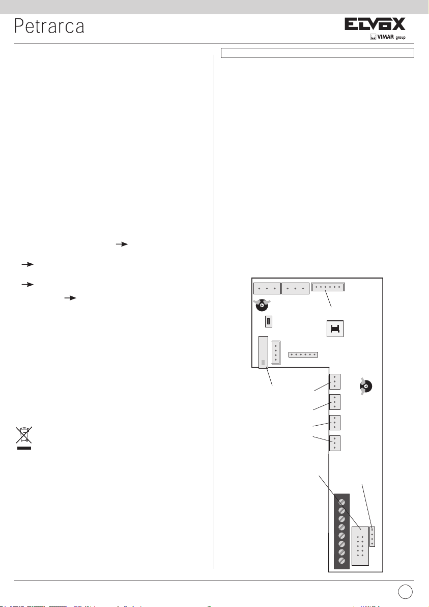
L’installazione del citofono può avvenire in versione da parete o in versione da tavolo
con l’ausilio dei kit di trasformazione art. 6140 o 6A40, oppure in abbinamento con
i monitor della serie Pertrarca art. 6029 (monitor in B/N) o art. 6029/C (monitor a
colori) per mezzo della staffa da parete art. 6145 o kit di trasformazione da tavolo
art. 6142 o 6A42.
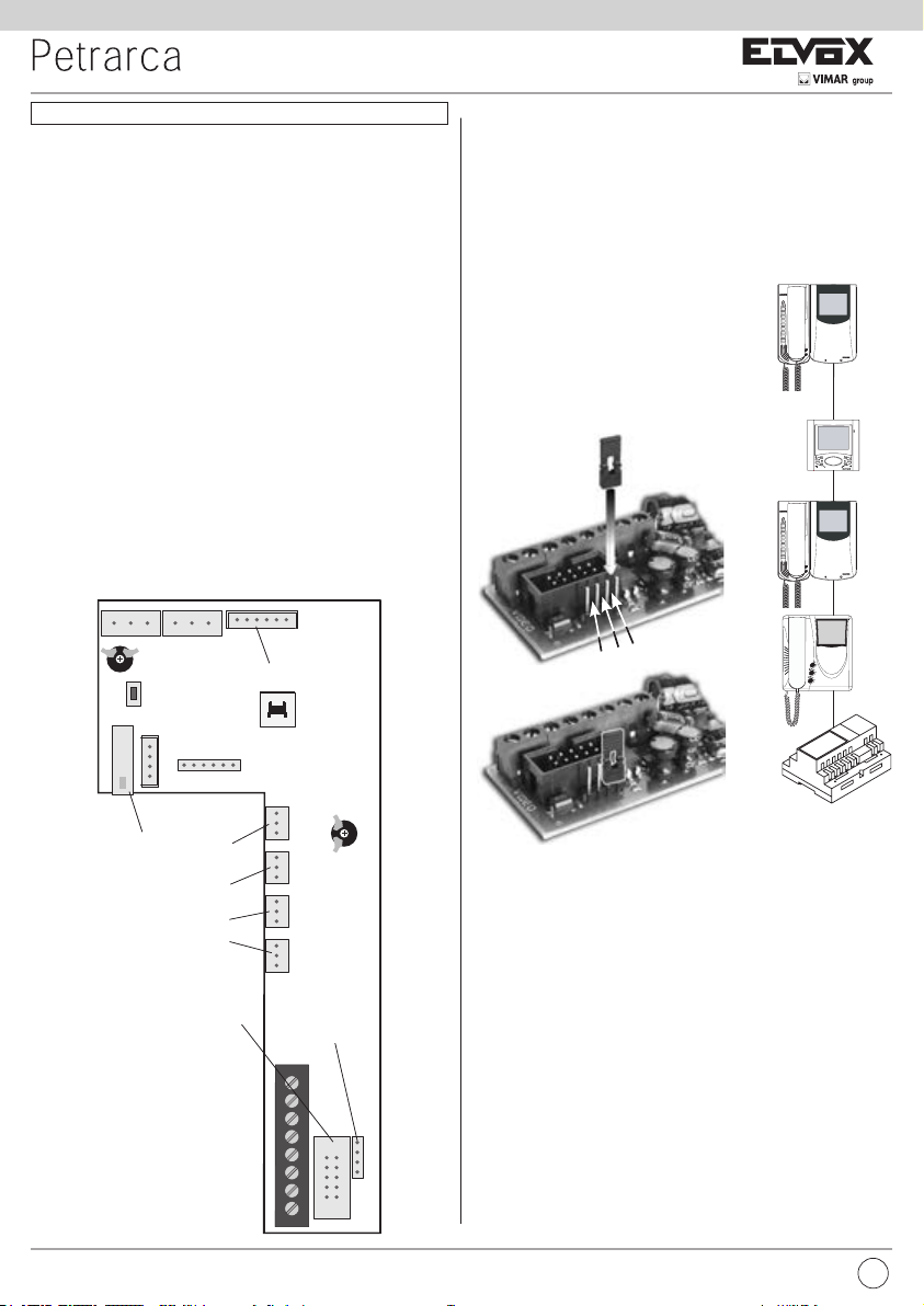
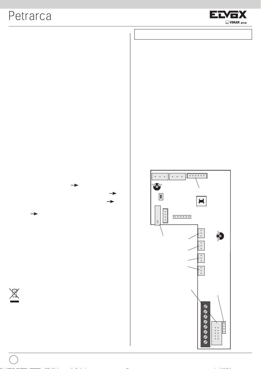
Morsettiera di collegamento e connettori
1, 2) Linea BUS.
4, 6P) Collegamento per pulsante di chiamata fuoriporta.
5, 6S) Collegamento suoneria supplementare.
-, +) Alimentazione supplementare per monitor con alimentatore art. 6923.
VARIAT.) Collegamento per modulo art. 6153/682.
VIDEO) Collegamento per monitor art. 6029 o 6029/C.
T1) 1° coppia di pulsanti art. 692P.
T2) 2° coppia di pulsanti art. 692P.
T3) 3° coppia di pulsanti art. 692P.
T4) 4° coppia di pulsanti art. 692P.
Regolazioni
Il volume di chiamata è regolabile spostando il lo dell’altoparlante tra il connettore
A+ (tono alto) e A- (tono basso), altrimenti utilizzare l’accessorio Art. 6153/682, la-
sciando il lo dell’altoparlante collegato al connettore A-.
INSTALLAZIONE
L’installazione del citofono da esterno parete non richiede accessori supplementari.
È possibile comunque predisporre una scatola in verticale da 3 moduli per agevolare
il ssaggio e il passaggio dei cavi. Per l’installazione da tavolo e in abbinamento al
monitor vedere rispettivamente le istruzioni dei kit di trasformazione e dei monitor.
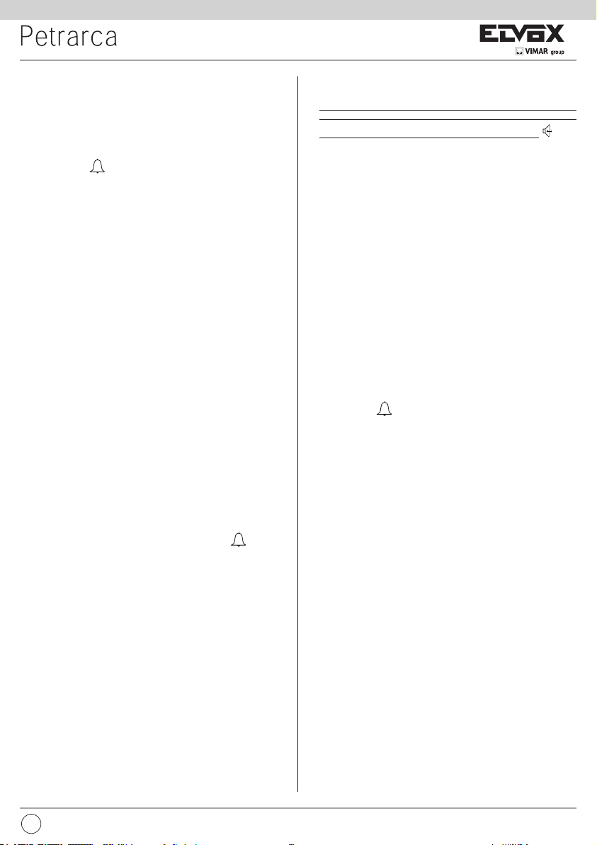
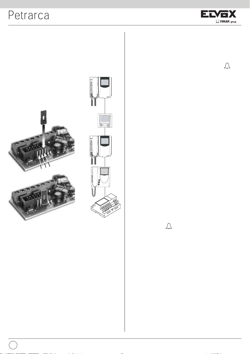
Terminazione Bus per stabilizzazione del segnale video
All’interno del citofono è presente un “connettore di termi
nazione BUS” (A-B-C) per la stabilizzazione del segnale
video.
A seconda della congurazione di collegamento (citofoni/
videocitofoni collegati in serie o derivati ad un distributore) settare in ponticello sul connettore ABC come descritto nella nota “Terminazione bus per impianti DUE
FILI ELVOX” riportata in seguito, nella sezione schemi di
collegamento.
Fig. 3
-
B
A
A
Fig. 1
BL BIRO A+ CAA- VARIAT.
TR1
Per art. 6153/682
RESET
SERR.
SERRATURA
PRG.
SERIALE
T1
T2
T3
T4
Per art. 6029
Per art. 6009 o
ou 6029/C
6009/C
1
2
4
5
6S
6P
-
+
TR2
T1
T2
T3
T4
Stabilizzazione
segnale video
VIDEO
1
A
B
C
PROGRAMMAZIONE
Le programmazioni del citofono sono di tre tipi: assegnazione codice identicativo o
codice di chiamata (indispensabile), assegnazione codice identicativo secondario
(per citofoni associati ad un citofono di capo gruppo), programmazione pulsanti per
servizi ausiliari e chiamate intercomunicanti (dove necessario). Le programmazioni
devono essere effettuate con l’impianto acceso, senza comunicazioni attive e solamente dopo aver collegato i citofoni/videocitofoni all’impianto e programmato le
targhe.
Programmazione codice identicativo
Il codice identicativo va programmato per mezzo di una targa (principale-MASTER),
presente nell’impianto e già congurata. Il citofono viene fornito senza codice identicativo assocciato. Per vericare ciò premere il pulsante serratura e il citofono
emetterà un triplo “Bip”.
Attenzione: durante la programmazione del codice di identicazione del citofono/videocitofono si hanno a disposizione 30 secondi dal momento in cui
si entra in programmazione nel citofono/videocitofono al momento in cui si
preme il pulsante di chiamata sulla targa o si invia il codice.
Fase di programmazione:
1) Togliere il coperchio del citofono.
2) Premere e mantenere premuto il pulsante RESET presente nel citofono.
A
Fig. 2
2
IT
3) Premere e mantenere premuto la lamella corrispondente al pulsante serratura
assieme al pulsante RESET.
4) Rilasciare il pulsante RESET, continuando a tenere premuto il pulsante serra
tura.
5) Dopo 2 secondi il citofono emette un tono acuto e viene messo in comunica
zione con la targa. Se al citofono è collegato anche il monitor, quest’ultimo viene
acceso e connesso alla telecamera della targa.
6) Rilasciare la lamella corrispondente alla serratura.
7) Nelle targhe a pulsanti premere il pulsante di chiamata corrispondente al cito
fono, invece nelle targhe alfanumeriche comporre il codice di chiamata e pre-
mere il pulsante “ ”.
8) Se nell’impianto esiste già un citofono con lo stesso codice identicativo asso
ciato, la targa emette un segnale sonoro basso ed è necessario ripetere l’operazione dal punto 2.
9) In caso contrario il codice viene associato al citofono e la comunicazione viene
terminata.
Programmazione codice identicativo secondario
La programmazione del codice identicativo secondario è richiesta solamente
quando si vuole far suonare contemporaneamente più di un citofono con lo stesso
pulsante o codice di chiamata. I citofoni che devono suonare contemporanemente
vengono associati ad uno stesso gruppo. Il citofono “capogruppo” viene program
mato per primo attraverso la precedente procedura “programmazione codice
identicativo”, invece i citofoni aggiuntivi del gruppo vengono programmati con il
codice identicativo secondario (vedi tabella riportata nella sezione schemi di col-
legamento). Il numero di citofoni che si possono associare ad uno stesso gruppo,
senza l’ausilio del programmatore art. 950C o SaveProg, sono 3 più un capogruppo.
Nel caso che ai citofoni siano abbinati i monitor Petrarca, è necessario aggiungere un alimentatore supplementare art. 6923 per ogni monitor aggiuntivo
dopo il secondo monitor. Utilizzando il programmatore art. 950C, è possibile
programmare l’attivazione della suoneria di tutti i videocitofoni senza far accendere contemporaneamente tutti i monitor per poi accendere il monitor, dal
videocitofono da cui si risponderà con il pulsante di autoaccensione; ciò per
mette di non utilizzare alimentatori supplementari.
Fase di programmazione:
1) Togliere il coperchio del citofono.
2) Premere e mantenere premuto il pulsante RESET presente nel citofono.
3) Premere e mantenere premuti la lamella corrispondente al pulsante serratura e
il pulsante di autoinserimento/autoaccensione (il 1° pulsante sotto alla lamella),
assieme al pulsante RESET.
4) Rilasciare il pulsante RESET, continuando a tenere premuti gli altri 2 pulsanti.
5) Dopo 2 secondi il citofono emette un tono acuto e viene messo in comunicazione
con la targa. Se al citofono è collegato anche il monitor, quest’ultimo viene acceso e connesso alla telecamera della targa.
6) Rilasciare la lamella corrispondente alla serratura e il pulsante di autoinserimento/autoaccensione.
7) Nelle targhe a pulsanti premere il pulsante di chiamata corrispondente al citofono
di “capogruppo”, invece nelle targhe alfanumeriche comporre lo stesso codice di
chiamata del citofono di “capogruppo” e premere il pulsante “
8) Associato l’identicativo secondario al citofono, la comunicazione viene termi
nata.
Per conoscere il numero assegnato fare riferimento alla tabella riportata nella se
zione schemi di collegamento.
Programmazione pulsanti
Il citofono viene fornito con una coppia di pulsanti aggiuntivi art. 692P, per le funzioni
di autoinserimento/autoaccensione e per il servizio ausiliario “luce scale”, il quale
attiva il 1° relè del 1° attuatore (art. 69RH), se collegato all’impianto. È possibile
inserire nel citofono altre 3 coppie di pulsanti art. 692P, da collegare ai connettori
T2-T3-T4, ai quali corrispondo le seguenti funzioni di default.
Pulsante Connettore In program. Funzione di default
1° T1 P1 Autoinserimento
/autoaccensione
2° T1 P2 Luce scale
(1° relè del 1° attuatore, art. 69RH)
3° T2 P3 Ausiliario
(2° relè del 1° attuatore, art. 69RH)
4° T2 P4 Non associato
5° T3 P5 Non associato
6° T3 P6 Non associato
7° T4 P7 Funzione F1 della targa
8° T4 P8 Funzione F2 della targa
Il tasto serratura è P0.
Per cambiare il tipo di funzionamento dei pulsanti P0 e P1 è necessario utilizzare il
-
-
-
-
-
-
”.
-
-
programmatore art. 950C o il Software Save Prog.
Programmazione pulsanti per chiamate intercomunicanti
Fase di programmazione:
1) Sganciare il microtelefono del citofono/videocitofono da chiamare, se della
serie 8870, Giotto,Petrarca. Per tutte le versioni della serie 6600 (senza
microtelefono), premere e tenere premuto il tasto parla/ascolta
2) Togliere il coperchio del citofono da programmare.
3) Premere e mantenere premuto il pulsante RESET presente nel citofono da pro
grammare.
4) Premere e mantenere premuto il pulsante supplementare per eseguire la chiamata intercomunicante assieme al pulsante RESET.
5) Rilasciare il pulsante RESET, continuando a tenere premuto il pulsante di chia
mata.
6) Dopo 2 secondi il citofono emette un tono acuto, mentre l’altro citofono emette
una scala tritonale ascendente.
7) Rilasciare il pulsante relativo alla chiamata intercomunicante.
8) Premere nel citofono chiamato (quello con il suono tritonale), uno dei pulsanti
programmati (come serratura, F1, F2 o attuatore).
9) Un tono acuto conferma la ne della procedura.
Ripetere la stessa procedura anche per gli altri citofoni ed eventuali pulsanti di
chiamata intercomunicante.
Programmazione pulsante autoaccensione verso targa specica.
Fase di programmazione:
1) Togliere il coperchio del citofono.
2) Premere e mantenere premuto il pulsante RESET presente nel citofono.
3) Premere e mantenere premuto il pulsante supplementare per eseguire l’autoaccensione assieme al pulsante RESET
4) Rilasciare il pulsante RESET, continuando a tenere premuto il pulsante autoaccensione.
5) Dopo 2 secondi il citofono emette un tono acuto.
6) Rilasciare il pulsante relativo all’autoaccensione.
7) Nelle targhe a pulsanti premere il pulsante di chiamata corrispondente al citofono, invece nelle targhe alfanumeriche comporre il codice di chiamata e pre-
mere il pulsante “ ”.
8) Un tono acuto conferma la ne della procedura.
Riprogrammazione valore di default dei pulsanti (P2,P3,P4,P5,P6,P7,P8)
Fase di programmazione:
1) Togliere il coperchio del citofono.
2) Premere e mantenere premuto il pulsante RESET presente nel citofono.
3) Premere e mantenere premuto il pulsante interessato da riprogrammare assieme
al pulsante RESET.
4) Rilasciare il pulsante RESET, continuando a tenere premuto l’altro pulsante.
5) Dopo 2 secondi il citofono emette un tono acuto.
6) Rilasciare il pulsante da riportare a default e ripremerlo.
Cancellazione totale delle programmazioni.
Fase di programmazione:
Questa procedura è consigliata quando si vuole cambiare l’ID di un citofono/
videocitofono precedentemente programmato e non si vuole mantenere la
programmazione di funzionamento dell’apparecchio.
1) Togliere il coperchio del citofono.
2) Premere e mantenere premuto il pulsante RESET presente nel citofono.
3) Premere e mantenere premuto il pulsante di autoaccensione assieme al pulsante
RESET.
4) Rilasciare il pulsante RESET, continuando a tenere premuto il pulsante autoaccensione.
5) Dopo 2 secondi il citofono emette, per 2 secondi, un tono lungo.
6) Rilasciare il pulsante autoaccensione.
7) Durante il tono lungo, premere la lamella del pulsante serratura.
Se la procedura di cancellazione è andata a buon ne, premendo nuovamente la
lamella della serratura il citofono emetterà un triplo “Bip”.
FUNZIONAMENTO
Le chiamate da targa esterna, intercomunicante e fuoriporta sono differenziate tra
loro da toni diversi.
Chiamata da targa.
Le chiamate da targa non seguono la pressione del pulsante di chiamata ma ven
gono generate internamente dal citofono. Il periodo di chiamata è 1 s di suono e 2 s
di pausa ripetuto per 2 volte (valore di default impostato nella targa). Per rispondere,
sollevare il microtelefono. Se il microtelefono è già sollevato durante la chiamata
riagganciare e risollevarlo. Il tempo di risposta alla chiamata (30 s) e il tempo di
conversazione (2 minuti di default) sono impostati nei parametri della targa. Scaduto
il tempo di conversazione, si può continuare, senza riagganciare il microtelefono, se
.
-
-
-
IT
3
ELVOX
CS2350
271103
4 3 2 1
A S+BUS
12 13 V3 M
EXT. 24V
F.P.
+ -
CN2
C
B
A
CN1
Stabilizzazione
segnale video
Per monitor
viene eseguita di nuovo la chiamata entro 10 s dalla stessa targa.
Chiamata intercomunicante.
Sollevare il microtelefono del citofono, premere il pulsante intercomunicante relativo al citofono/videocitofono da chiamare. Nel microtelefono del citofono chiamante
si udrà un tono di chiamata (se la chiamata è possibile) o tono di occupato (se
la chiamata non è possibile). Nel citofono chiamato la suoneria inizierà a suonare
ciclicamente con un ritmo di 1 s di suono e 4 s di pausa. La durata massima della
chiamata sarà di 30 s (6 cicli). Per rispondere alla chiamata è sufciente sollevare il
microtelefono; la durata massima della conversazione è di 5 minuti. Scaduto il tempo
di conversazione si può continuare la conversazione, senza riagganciare il microtelefono, se viene eseguita di nuovo la chiamata entro 10 s. Un’eventuale chiamata
da targa ha priorità su quella intercomunicante.
Chiamate riutate.
L’installazione dell’art. 6153/682 nel citofono, permette di variare l’intensità di chiamata o di escludere il suono di chiamata. L’esclusione della chiamata è indicata
dall’accensione permanente del LED rosso. Se vengono eseguite delle chiamate
verso il citofono quando è in condizione di chiamata esclusa, queste vengono riutate. Il riuto delle chiamate determina un breve spegnimento del LED rosso tante
volte sono le chiamate escluse (massimo chiamate escluse 4). La segnalazione
viene ripetuta ogni 10 s circa. La cancellazione delle chiamate riutate avviene con:
la riabilitazione della suoneria, con il reset del citofono o l’assenza di alimentazione
nell’impianto. Nelle targa il riuto è segnalato con il tono dissuasione (una serie di
“Bip” di 100ms con pausa di 100ms per 5 totali). Nella targa con display viene anche
visualizzato il messaggio “Non disturbare”.
Tasto Serratura
Il tasto serratura di ogni apparecchio funziona nel modo seguente.
- Apparecchio con microtelefono a riposo serratura verso l’ultima targa con
la quale ha parlato o dalla quale è stato chiamato.
- Apparecchio con microtelefono sollevato ma non impegnato in conversazione
chiamata a centralino se il ag Centralino è SI. Altrimenti si riconduce al
primo caso.
- Apparecchio con microtelefono sollevato e impegnato in conversazione interna
come il primo caso.
- Apparecchio con microtelefono sollevato e impegnato in conversazione esterna o
chiamato da targa serratura verso la targa con la quale sta parlando o dalla
quale è chiamato.
In pratica si va ad azionare una serratura sempre tranne quando si alza il microtelefono e si preme subito il pulsante serratura. Portare anche questo al caso standard
si può se nell’impianto non c’è il centralino di portineria e se si pone il ag Centralino
a NO.
The instruction manual is downloadable from the site www.vimar.com
DESCRIPTION
Type 6209 is an interphone in the Petrarca series for ELVOX 2-WIRE audio and
video door entry systems. It is supplied as standard with 3 pushbuttons, one for
lock release, one for self-start of the interphone in the system even when not called,
and one for the auxiliary “stair light” service. The interphone can be tted with an
additional 3 pairs of pushbutton types 692P (692P/M or 692P/R), for auxiliary services or intercommunicating calls, and the accessory type 6153/682 for: call volume
adjustment, call signal mute, call denied luminous indicators, signal to indicate unanswered calls, signal to indicate services not available and luminous signal for gate/
door open. The interphone can be installed as a wall-mounted version or desktop
using the conversion kit type 6140 or 6A40, or in combination with monitors in the
Petrarca series type 6029 (b/w monitor) or type 6029/C (colour monitor) by means of
wall bracket type 6145 or desktop conversion kit type 6142 or 6A42.
Connection and connector terminal board
1, 2) BUS line.
4, 6P) Connection for door call pushbutton.
5, 6S) Connection of additional door ringtone
-, +) Additional power supply for monitor with power supply type 6923.
VARIAT.) Connection for module type 6153/682.
VIDEO) Connection for monitor type 6029 or 6029/C.
T1) 1st pair of pushbuttons type 692P.
T2) 2nd pair of pushbuttons type 692P.
T3) 3rd pair of pushbuttons type 692P.
T4) 4th pair of pushbuttons type 692P
TR1, TR2) Do not touch, trimmers already set by the rm.
Fig. 1
BL BIRO A+ CAA- VARIAT.
TR1
RESET
.
For
Per art. 6153/682
REGOLE DI INSTALLAZIONE.
L’installazione deve essere effettuata con l’osservanza delle disposizioni regolanti
l’installazione del materiale elettrico in vigore nel Paese dove i prodotti sono installati.
CONFORMITÀ NORMATIVA.
Direttiva EMC
Norme EN 60065, EN 61000-6-1 e EN 61000-6-3.
INFORMAZIONE AGLI UTENTI AI SENSI DELLA DIRETTIVA 2012/19/
UE (RAEE)
Al ne di evitare danni all’ambiente e alla salute umana oltre che di incorre
re in sanzioni amministrative, l’apparecchiatura che riporta questo simbolo
dovrà essere smaltita separatamente dai riuti urbani ovvero riconsegnata
al distributore all’atto dell’acquisto di una nuova. La raccolta dell’apparecchiatura
contrassegnata con il simbolo del bidone barrato dovrà avvenire in conformità alle
istruzioni emanate dagli enti territorialmente preposti allo smaltimento dei riuti. Per
maggiori informazioni contattare il numero verde 800-862307.
4
SERR.
SERRATURA
-
PRG.
SERIALE
Lock
T1
T2
T3
T4
Per type 6029
Per art. 6009 o
ou 6029/C
6009/C
T1
T2
T3
T4
Video signal
Stabilizzazione
stabiliser
segnale video
1
2
4
5
6S
6P
-
+
TR2
1
VIDEO
EN
Controls
The call volume can be adjusted by moving the loudspeaker wire from connector A+
(high) to A- (low); otherwise use accessory type 6153/682, leaving the loudspeaker
wire connected to connector A-.
INSTALLATION
Wall-mounted installations of the interphone do not require additional accessories.
However a vertical 3-module box may be used to facilitate xture and cable routing.
For desktop installations and combinations with monitors, refer to the respective
instructions of the conversion kit or monitor.
Bus termination for video signal stabilisation
The interphone is provided with a “BUS termination con
nector” (A-B-C) for video signal stabilisation.
Depending on the connection conguration (interphones/
monitors connected in series or derived from a distributor),
set a jumper on the connector ABC as described in the
note “Bus termination for ELVOX TWO-WIRE INSTALLATIONS” in the wiring diagrams section below.
-
B
Fig. 3
A
A
A
B
C
A
Fig. 2
PROGRAMMING
There are three interphone programming modes: assignment of an identication
code or call code (indispensable), assignment of a secondary identication code (for
interphones associated with a master interphone), programming of pushbuttons for
auxiliary services and intercommunicating calls (when necessary).
Programming must be performed with the system switched on, without active com
munication and only after connecting the interphones/monitors to the system and
programming the panels.
Identication code programming
The identication code is programmed via an entrance panel (MASTER), already
congured and present on the system. The interphone is supplied without associated
identication code. To verify this condition, press the lock release pushbutton and the
interphone should emit a triple “Beep”.
Attention: during the interphone/video interphone identication code programming you have 30 seconds from the moment you enter the programming in the
interphone/video interphone and the moment you press the call push-button
on the panel or you send the code.
Programming phase:
1) Remove the interphone cover.
-
2) Press and hold the RESET pushbutton on the interphone.
3) Press and hold the tab on the lock release pushbutton, together with the RESET
pushbutton.
4) Release the RESET pushbutton, keeping the lock release pushbutton pressed.
5) After 2 seconds the interphone emits a high tone and communication is enabled
with the panel. If the monitor is also connected to the interphone, it is switched
on and connected to the camera of the entrance panel.
6) Release the tab of the lock release pushbutton.
7) On pushbutton entrance panels, press the call button for the interphone, while on
alphanumeric keypads, enter the call code and press pushbutton “
8) If the system contains an interphone that already has the same associated iden-
tication code, the panel emits a low signal and the operation should be repeated
from point 2.
9) Otherwise the code is associated with the interphone and communication is terminated.
Secondary identication code programming
Programming of the secondary identication code is only required when more than
one interphone is to be called by means of the same pushbutton or call code. The
interphones that ring at the same time are associated with the same group. The
“master” interphone is programmed rst by means of the “identication code programming” procedure described above, while the additional group interphones are
programmed with the secondary identication code (see table shown in the wiring
diagram section).
A maximum of three audio door entry units plus one group master can be associated with the same group, without the need for programmer Type 950C or
SaveProg .
If the interphones are combined with Petrarca monitors, an additional power
supply type 6923 must be tted for each additional monitor after the second
monitor. Using programmer type 950C, activation of the ringtone on all monitors can be programmed, without simultaneous activation of all monitors,
to then enable activation of the monitor from the interphone used to answer
the call with the self-start pushbutton; this avoids the need to use additional
power supplies.
Programming phase:
1) Remove the interphone cover.
2) Press and hold the RESET pushbutton on the interphone.
3) Press and hold the tab on the lock release pushbutton and the self start/auto-ac-
tivation pushbutton (the rst pushbutton below the tab), together with the RESET
pushbutton.
4) Release the RESET pushbutton, keeping the other two pushbuttons pressed.
5) After 2 seconds the interphone emits a high tone and communication is enabled
with the panel. If the monitor is also connected to the interphone, it is switched
on and connected to the camera of the entrance panel.
6) Release the tab on the lock release pushbutton and the self start pushbutton.
7) On pushbutton entrance panels, press the call button for the “master” interphone,
while on alphanumeric keypads, enter the call code of the “master” interphone
and press pushbutton “
8) When the secondary code is associated with the interphone and communication
is terminated.
To know the number assigned see table shown in the wiring diagram section.
Pushbutton programming
The interphone is supplied with a pair of additional pushbuttons type 692P, for the
functions self start and the auxiliary service “stair light”, which activates the 1st relay
of the 1st actuator (type 692R), if connected to the system. A further three pairs of
pushbuttons type 692P can be inserted in the interphone, to be connected to connectors T2-T3-T4, corresponding to the following default functions.
Pushbutton Connector In program. Default function
1° T1 P1 Self-start
2° T1 P2 Stair light
(1st relay of 1st actuator, type 692R)
3° T2 P3 Auxiliary
(2nd relay of 1st actuator, type 692R)
4° T2 P4 Not associated
5° T3 P5 Not associated
6° T3 P6 Not associated
7° T4 P7 Function F1 on panel
8° T4 P8 Function F2 on panel
P0 is the lock button.
To change the operating mode of buttons P0 and P1, use programmer type 950C
or the Save Prog software.
”.
”.
EN
5
Intercommunicating call pushbutton programming
Programming phase:
1) Raise the handset of the interphone/video interphone to call (when using
series 8870, Giotto, Petrarca). With other versions of series 6600 (without
handset) press and keep pressed the talk/listen push-button
2) Remove the cover of the interphone to be programmed.
3) Press and hold the RESET push-button on the audio door entry unit to program.
4) Press and hold the additional pushbutton to make the intercommunicating call
together with the RESET pushbutton.
5) Release the RESET pushbutton, keeping the call pushbutton pressed.
6) After 2 seconds the interphone emits a high tone, while the other interphone
emits a 3-tone ascending scale.
7) Release the intercommunicating call pushbutton.
8) On the interphone called (with the 3-tone ring), press one of the programmed
pushbuttons (such as lock, F1, F2 or actuator).
9) A high tone conrms the end of the procedure.
Repeat the same procedure for the other interphones and any other intercommunicating call pushbuttons.
Programming the self-start pushbutton to a specic panel.
Programming phase:
1) Remove the interphone cover.
2) Press and hold the RESET pushbutton on the interphone.
3) Press and hold the additional pushbutton to activate the self-start function together with the RESET pushbutton.
4) Release the RESET pushbutton, keeping the self-start pushbutton pressed.
5) After 2 seconds the interphone emits a high tone.
6) Release the self-start pushbutton.
7) On pushbutton entrance panels, press the call button for the interphone, while on
alphanumeric keypads, enter the call code and press pushbutton “
8) A high tone conrms the end of the procedure.
Restoring default values of pushbuttons (P2,P3,P4,P5,P6,P7,P8)
Programming phase:
1) Remove the interphone cover.
2) Press and hold the RESET pushbutton on the interphone.
3) Press and hold the relative pushbutton to be reprogrammed together with the
RESET pushbutton.
4) Release the RESET pushbutton, keeping the other pushbutton pressed.
5) After 2 seconds the interphone emits a high tone.
6) Release the pushbutton to restore to default and then press again.
Deleting all settings.
Programming phase:
This procedure is advised when you want to change the ID of an interphone/monitor
previously programmed and you do not want keep the operation programming of
the appliance.
1) Remove the interphone cover.
2) Press and hold the RESET pushbutton on the interphone.
3) Press and hold the self start pushbutton together with the RESET pushbutton.
4) Release the RESET pushbutton, keeping the self-start pushbutton pressed.
5) After 2 seconds the interphone emits a continuous tone for two seconds.
6) Release the self-start pushbutton.
7) During the continuous tone, press the tab on the lock release pushbutton.
If the deletion procedure is successful, when the lock release tab is pressed once
more the interphone emits a triple “Beep”.
OPERATION
Calls from an entrance panel, intercommunicating calls and door calls are differentiated by means of different tones.
Door calls.
Calls from entrance panels do not follow the pressed pushbutton but are generated
inside the interphone. The call interval is 1 s of ringtone and 2 s of pause repeated
twice (default value set on panel). To answer, raise the handset. If the handset is
already raised during the call, replace and raise it again. The call answer time (30
s) and the conversation time (2 minutes by default) are set in the panel parameters.
When the conversation time has elapsed, the user can continue without replacing
the handset if a new call is made within 10 s from the same panel.
Intercommunicating call.
Lift the handset and press the intercommunicating button for the interphone/monitor
to be called. On the handset of the interphone called a call tone will ring (if the call is
enabled) or an engaged tone (if not enabled). On the called interphone the ringtone
starts sequentially at intervals of 1 s ringing and 4 s pause. The maximum duration of
the call is 30 s (6 cycles). To answer the call, simply raise the handset; the maximum
.
”.
duration of the conversation is 60 seconds. When the conversation time has elapsed,
the user can continue without replacing the handset if a new call is made within 10 s.
Calls from the panel have priority over intercommunicating calls.
Denied calls.
Installation of type 6153/682 in the interphone, enables the user to vary the call
intensity or mute the ringtone. Call mute is indicated by permanent illumination of
the red LED. If calls are made to the interphone when the call mute is enabled, they
are denied. A denied call causes the red Led to briey switch off according to the
number of times calls are denied (maximum 4 denied calls). The signal is repeated
every 10 s (approx.). Deletion of denied calls is by: reenabling the ringtone, resetting
the interphone or a system power failure. On the panel, a denied call is indicated by
means of a dissuasion tone (a series of “Beeps” at 100ms intervals with a pause of
100ms for a total of 5 s).
The message “Do not disturb” also appears on panels with display.
Lock Button
The lock button of each device works in the following manner.
- Device with handset at rest
spoken or from which it has been called.
- Device with handset raised but not engaged in a conversation call to switch-
board if the Switchboard ag is YES. Otherwise it goes back to the rst case.
- Device with handset raised and engaged in an internal conversation as in
the rst case.
- Device with handset raised and engaged in an external conversation or called
from entrance panel lock to the entrance panel being spoken with or from
which it has been called.
In practice a lock is always activated except when the handset is raised and you
immediately press the lock button. This can also be taken to the standard case if the
system has no porter switchboard and the Switchboard ag is set on NO.
INSTALLATION RULES.
Installation should be carried out observing current installation regulations for elec
trical systems in the Country where the products are installed.
CONFORMITY.
EMC directive
Standards EN 60065, EN 61000-6-1 and EN 61000-6-3.
INFORMATION FOR USERS UNDER DIRECTIVE 2012/19/UE (WEEE)
In order to avoid damage to the environment and human health as well
as any administrative sanctions, any appliance marked with this symbol
must be disposed of separately from municipal waste, that is it must be
reconsigned to the dealer upon purchase of a new one. Appliances marked
with the crossed out wheelie bin symbol must be collected in accordance with the
instructions issued by the local authorities responsible for waste disposal.
lock to the last entrance panel with which it has
-
6
EN

ELVOX
CS2350
271103
4 3 2 1
A S+BUS
12 13 V3 M
EXT. 24V
F.P.
+ -
CN2
C
B
A
CN1
Stabilizzazione
segnale video
Per monitor
Télécharger le manuel d’instructions sur le site www.vimar.com
DESCRIPTION
L’art. 6209 est un portier audio de la série Petrarca pour systèmes de portiers audio
ou vidéo 2 FILS ELVOX. Livré avec 3 boutons de série : un pour la commande de
la gâche, un pour l’allumage/extinction automatique du poste même sans appel et
un pour le service auxiliaire d’éclairage escalier. Le portier audio peut recevoir 3
autres paires de boutons art. 692P (692P/M o 692P/R) pour les services auxiliaires
ou la communication entre postes et l’accessoire art. 6153/682 pour : réglage du
volume d’appel, exclusion du signal d’appel, signalisation lumineuse d’appel exclu,
signalisation d’appel sans réponse et signalisation de services non disponibles et
signalisation lumineuse de porte ouverte/portail ouvert. L’installation du portier audio
est réalisable en version murale ou en version de table à l’aide des kits de transformation art. 6140 ou 6A40 ou bien en combinaison avec les moniteurs de la série
Petrarca art. 6029 (moniteur N/B) ou art. 6029/C (moniteur couleur) à l’aide de la
patte de support mural art. 6145 ou du kit de transformation version de table art.
6142 ou 6A42.
Bornier de connexion et connecteurs
1, 2) Ligne BUS.
4, 6P) Raccordement pour bouton-poussoir d’appel de palier
5, 6S) Raccordement sonnerie supplémentaire.
-, +) Alimentation supplémentaire pour moniteurs art. 6923.
VARIAT.) Raccordement pour module art. 6153/682.
VIDEO) Raccordement pour moniteur art. 6029 ou 6029/C.
T1) 1ère paire de boutons art. 692P.
T2) 2ème paire de boutons art. 692P.
T3) 3ème paire de boutons art. 692P.
T4) 4ème paire de boutons art. 692P.
TR1, TR2) Trimmers déjà reglés dans l’usine, ne toucher pas.
Fig. 1
BL BIRO A+ CAA- VARIAT.
Réglages
Le volume d’appel est réglable en déplaçant le l du haut-parleur entre le connecteur
A+ (ton haut) et A- (ton bas), sinon utiliser l’accessoire art. 6153/682 en laissant le
l du haut-parleur relié au connecteur A-.
INSTALLATION
L’installation en saillie du portier audio ne nécessite pas d’accessoires supplémen
taires. Toutefois, il est possible de prévoir une boîte 3 modules verticale pour faci-
liter la xation et le passage du câblage. Pour l’installation de la version de table
en combinaison avec le moniteur, voir respectivement les instructions des kits de
transformation et des moniteurs.
Terminaison Bus pour la stabilisation du signal vidéo
Un « connecteur de terminaison bus » (A-B-C) se trouve
à l’intérieur de l’interphone pour la stabilisation du signal
vidéo.
En fonction de la conguration de la connexion (inter
phones/moniteurs reliés en série ou dérivés à un distributeur), régler en pontet sur le connecteur ABC comme
décrit dans la note « Terminaison bus pour installations
DEUX FILS ELVOX » reportée ci-dessous, dans la section schémas de raccordement.
-
Fig. 3
-
B
A
A
FR
TR1
RESET
SERR.
SERIALE
Gãche
SERRATURA
Pour Art. 6029
Per art. 6009 o
ou 6029/C
6009/C
Pour
Per art. 6153/682
PRG.
T1
T1
T2
T2
T3
T3
T4
T4
Stabilisateur de
Stabilizzazione
signal vidéo
segnale video
1
2
4
5
6S
6P
-
+
VIDEO
TR2
1
A
B
C
PROGRAMMATION
Les programmations du portier audio sont de trois types : assignation d’un code
d’identication ou d’un code d’appel (indispensable), assignation d’un code d’identication secondaire (pour portiers audio associés à un portier audio “Master”), pro-
grammation des boutons pour services auxiliaires et la communication entre postes
(lorsque cela est nécessaire). Les programmations doivent être effectuées avec le
système allumé, sans communication en cours et seulement après avoir relié les
portiers audio et/ou vidéo au système et programmé les plaques de rue.
Programmation du code d’identication
Le code d’identication doit être programmé par l’intermédiaire d’une plaque de rue
(principale-”MASTER”), montée dans le système et déjà congurée. Le portier audio
est fourni sans code d’identication associé. Pour vérier cette condition, appuyer
sur le bouton de commande de la gâche. Le portier audio émettra un triple “Beep”.
Attention: pendant la programmation du code d’identication du poste d’appartement/portier-vidéo il y a 30 seconds du moment dans lequel on entre en
programmation dans le poste d’appartement/portier-vidéo au moment dans
lequel on appuie sur le bouton-poussoir d’appel ou on envoie le code.
Étapes de la programmation:
1) Déposer la face avant du portier audio.
A
Fig. 2
7

2) Appuyer et garder le doigt sur le bouton RESET du portier audio.
3) Appuyer et garder le doigt sur la lamelle correspondant au bouton de commande
de la gâche, en même temps que le bouton RESET.
4) Relâcher le bouton RESET tout en continuant à maintenir enfoncé le bouton de
commande de la gâche.
5) Après 2 secondes, le portier émet une tonalité aiguë et est mis en communica
tion avec la plaque de rue. Si le moniteur est également relié au portier audio,
celui-ci s’allume pour être connecté à la caméra de la plaque de rue.
6) Relâcher la lamelle correspondant à la gâche.
7) Appuyer sur le bouton d’appel correspondant au portier audio sur les plaques de
rue à boutons. Taper le code d’appel et appuyer sur le bouton II sur les plaques
de rue alphanumériques.
8) Si le système comprend déjà un portier audio avec le même code d’identication
associé, la plaque de rue émet un signal sonore faible et il faut nécessairement
reprendre l’opération du point 2.
9) Dans le cas contraire, le code est associé au portier audio et la communication
est coupée.
Programmation du code d’identication secondaire
La programmation du code d’identication secondaire n’est requise que pour
faire sonner simultanément plus d’un portier audio avec le même bouton ou code
d’appel. Les portiers audio qui doivent sonner simultanément sont associés à un
même groupe. Le portier audio “Master” est programmé en premier en utilisant la
procédure précédente de “programmation du code d’identication”, tandis que les
portiers audio supplémentaires du groupe sont programmés avec le code d’identi-
cation secondaire (voir table indiquée dans la section schémas de raccordement).
Le nombre d’interphones que l’on peut associer au même groupe, sans l’aide du
programmateur art. 950C ou SaveProg, est 3 plus un chef de groupe.
Dans le cas de combinaison des portiers audio avec les moniteurs Petrarca,
il faut nécessairement ajouter une alimentation supplémentaire art. 6923 pour
chaque moniteur en plus du deuxième moniteur. Avec le programmateur art.
950C, il est possible de programmer l’activation de la sonnerie de tous les
portiers vidéo sans allumer simultanément tous les moniteurs, pour allumer
ensuite le moniteur du portier audio, depuis lequel on reponara, appelé avec
le bouton d’auto-allumage. Cette solution permet ainsi de ne pas utiliser d’alimentations supplémentaires.
Étapes de la programmation :
1) Déposer la face avant du portier audio.
2) Appuyer et garder le doigt sur le bouton RESET du portier audio.
3) Appuyer et garder le doigt sur la lamelle correspondant au bouton de la gâche et
sur le bouton auto-enclenchement/auto-allumage (le 1er bouton sous la lamelle),
en même temps que le bouton RESET.
4) Relâcher le bouton RESET tout en maintenant enfoncés les deux autres boutons.
5) Après 2 secondes, le portier audio émet une tonalité aiguë et est mis en communication avec la plaque de rue. Si le moniteur est également relié au portier
audio, celui-ci s’allume pour être connecté à la caméra de la plaque de rue.
6) Relâcher la lamelle correspondant à la gâche et le bouton d’auto-enclenchement/auto-allumage.
7) Appuyer sur le bouton d’appel correspondant au portier audio “Master” sur les
plaques de rue à boutons. Taper le même code d’appel du portier audio “Master”
et appuyer sur le bouton “
8) Une fois l’identicateur secondaire associé au portier audio, la communication
est coupée.
Pour connaître le numéro assigné voir référence dans la table indiquée dans la
section schémas de raccordement.
Programmation des boutons
Le portier est fourni avec une paire de boutons supplémentaires art. 692P pour les
fonctions d’auto-enclenchement/auto-allumage et pour le service auxiliaire d’éclairage escalier, lequel active le 1er relais du 1er actionneur (art. 69RH), si connecté
au système. Il est possible en outre de prévoir trois autres paires de boutons art.
692P à relier aux connecteurs T2-T3-T4, auxquels sont associées les fonctions
par défaut ci-après.
Bouton Connecteur Prog. Fonction par défaut
1er T1 P1 Auto-enclenchement/auto-allumage
2ème T1 P2 Éclairage escalier (1er relais du 1er
actionneur, art. 692R)
3ème T2 P3 Auxiliaire (2ème relais du 1er
actionneur, art. 692R)
4ème T2 P4 Non associé
5ème T3 P5 Non associé
6ème T3 P6 Non associé
7ème T4 P7 Fonction F1 de la plaque de rue
8ème T4 P9 Fonction F2 de la plaque de rue
P0 est la touche gâche.
” sur les plaques de rue alphanumériques.
-
Pour changer le type de fonctionnement des boutons P0 et P1, il est nécessaire
d’utiliser le programmateur art. 950C ou le logiciel Save Prog.
Programmation des boutons pour communication entre postes
Étapes de la programmation:
1) Décrocher le combiné du poste d’appartement/portier-vidéo (lorsqu’on
utilise la série 8870, Giotto, Petrarca). Dans les autres versions de la série
6600 (sans combiné) appuyer et maintenir enfoncé le poussoir parle/écoute
.
2) Déposer la face avant du portier audio à programmer.
3) Appuyer sans relâcher sur le bouton RESET de l’interphone à programmer.
4) Appuyer et garder le doigt sur le bouton de communication entre postes supplémentaire, en même temps que le bouton RESET.
5) Relâcher le bouton RESET tout en continuant à maintenir enfoncé le bouton
d’appel.
6) Après 2 secondes, le portier audio émet une tonalité aiguë, tandis que l’autre
portier audio émet une échelle triton ascendante.
7) Relâcher le bouton de communication entre postes.
8) Appuyer sur un des boutons programmés (comme gâche, F1, F2 ou actionneur)
du portier audio appelé (celui qui émet le son triton).
9) Une tonalité aiguë conrme la n de la procédure.
Répéter aussi la même procédure pour les autres portiers audio et éventuels boutons d’appel pour communication entre deux postes.
Programmation du bouton d’auto-allumage vers la plaque de rue spécique.
Étapes de la programmation:
1) Déposer la face avant du portier audio.
2) Appuyer et garder le doigt sur le bouton RESET du portier audio.
3) Appuyer et garder le doigt sur le bouton d’auto-allumage supplémentaire, en
même temps que le bouton RESET
4) Relâcher le bouton RESET tout en continuant à maintenir enfoncé le bouton
d’auto-allumage.
5) Le portier audio émet une tonalité aiguë après 2 secondes.
6) Relâcher le bouton d’auto-allumage.
7) Appuyer sur le bouton d’appel correspondant au portier audio sur les plaques de
rue à boutons. Taper le code d’appel et appuyer sur le bouton “
plaques de rue alphanumériques.
8) Une tonalité aiguë conrme la n de la procédure.
Reprogrammation de la valeur par défaut (autrement dit d’usine) des boutons
(P2,P3,P4,P5,P6,P7,P8)
Étapes de la programmation:
1) Déposer la face avant du portier audio.
2) Appuyer et garder le doigt sur le bouton RESET du portier audio.
3) Appuyer et garder le doigt sur le bouton à reprogrammer, en même temps que
le bouton RESET.
4) Relâcher le bouton RESET tout en continuant à maintenir enfoncé l’autre bouton.
5) Le portier audio émet une tonalité aiguë après 2 secondes.
6) Relâcher le bouton à reprogrammer à la valeur par défaut et appuyer à nouveau
sur celui-ci.
Effacement des programmations.
Étapes de la programmation:
Cette procédure est conseillée lorsqu’on veut changer l’ID d’un portier audio/portier
vidéo précédemment programmé et on ne veut pas maintenir la programmation de
fonctionnement de l’appareil.
1) Déposer la face avant du portier audio.
2) Appuyer et garder le doigt sur le bouton RESET du portier audio.
3) Appuyer et garder le doigt sur le bouton d’auto-allumage, en même temps que
le bouton RESET.
4) Relâcher le bouton RESET tout en continuant à maintenir enfoncé le bouton
d’auto-allumage.
5) Après 2 secondes, le portier audio émet une tonalité longue pendant 2 secondes.
6) Relâcher le bouton d’auto-allumage.
7) Pendant le retentissement de la tonalité longue, appuyer sur la lamelle du bouton
de commande de la gâche.
Si la procédure d’effacement est réussie, le portier audio émettra de nouveau un
triple “Beep” en appuyant sur la lamelle de la gâche.
FONCTIONNEMENT
Les appels de palier, de la plaque de rue et pour communication entre postes se
distinguent par leur tonalité différente.
” sur les
8
FR
ELVOX
CS2350
271103
4 3 2 1
A S+BUS
12 13 V3 M
EXT. 24V
F.P.
+ -
CN2
C
B
A
CN1
Stabilizzazione
segnale video
Per monitor
Appel de la plaque de rue.
Les appels de la plaque de rue ne répondent pas à la pression du bouton, mais sont
générés à l’intérieur par le portier audio. La période d’appel est de 1 s de tonalité et
de 2 s de pause, qui se répète deux fois (valeur par défaut dénie dans la plaque de
rue). Pour répondre, décrocher le combiné. Si le combiné est déjà soulevé pendant
l’appel, le raccrocher puis le décrocher à nouveau. Le temps de réponse à l’appel
(30 s) et la durée de conversation (2 minutes par défaut) sont dénies dans les
paramètres de la plaque de rue. Une fois la durée de conversation écoulée, il est
possible de continuer à dialoguer, sans raccrocher le combiné, si un autre appel est
effectué depuis la même plaque de rue dans les 10 s qui suivent.
Appel pour communication entre postes.
Décrocher le combiné du portier audio, appuyer sur le bouton de communication
entre postes du portier audio ou vidéo à appeler. Le combiné du portier audio appelant émettra une tonalité d’appel (si l’appel est possible) ou une tonalité occupé
(si l’appel est impossible). La sonnerie du portier appelé commencera à retentir par
séquences répétitives de 1 s de tonalité et de 4 s de pause. La durée maximale de
l’appel sera de 30 s (6 séquences). Pour répondre à l’appel, il suft de soulever le
combiné; la durée maximale de la conversation est de 5 minutes. Une fois la durée
de conversation écoulée, il est possible de continuer à dialoguer, sans raccrocher le
combiné, si un visiteur appelle de nouveau dans les 10 s qui suivent. Un appel éventuel depuis la plaque de rue est prioritaire sur celui pour communication entre postes.
Appels refusés.
Le montage de l’art. 6153/682 dans le portier permet de varier le volume sonore
de l’appel ou d’exclure la tonalité d’appel. L’exclusion de l’appel est signalée par
l’allumage (lumière xe) de la LED rouge. Si des appels sont effectués vers le portier audio lorsqu’il est en condition d’appel exclu, ceux-ci sont refusés. Le refus
des appels détermine une extinction de courte durée de la LED rouge pour chaque
appel exclu (4 au maximum). La signalisation est répétée environ toutes les 10 s.
L’effacement des appels refusés se produit : avec le rétablissement de la sonnerie,
avec la réinitialisation du portier audio ou à défaut d’alimentation du système. Le
refus, sur la plaque de rue, est signalé par la tonalité de dissuasion (une série de
“Beep” de 100 ms avec une pause de 100 ms pendant une durée totale de 5 s).Le
message “Ne pas déranger” apparaît en plus sur la plaque de rue avec moniteur.
Touche Gâche
La touche gâche de chaque appareil fonctionne de la manière suivante.
- Appareil avec combiné au repos gâche vers la dernière plaque avec laquelle il a parlé ou à partir de laquelle il a été appelé.
- Appareil avec combiné soulevé mais non engagé en conversation appel
au standard si le ag Standard est OUI. Sinon, on retourne au premier cas.
- Appareil avec combiné soulevé et engagé en conversation interne comme
le premier cas.
- Appareil avec combiné soulevé et engagé en conversation externe ou appel depuis plaque gâche vers la plaque avec laquelle il parle ou depuis laquelle
il est appelé.
En fait, on actionne toujours une gâche sauf lorsque l’on soulève le combiné et l’on
appuie tout de suite sur le bouton gâche. Il est possible de le mettre au cas normal si
le standard de conciergerie est absent dans l’installation et l’on met le ag Standard
à NON.
RÈGLES D’INSTALLATION.
L’installation doit être effectuée dans le respect des dispositions régulant l’installation du matériel électrique en vigueur dans le Pays d’installation des produits.
CONFORMITÉ AUX NORMES.
Directive EMC
Normes EN 60065, EN 61000-6-1 et EN 61000-6-3.
COMMUNICATION AUX UTILISATEURS CONFORMÉMENT À LA DI
RECTIVE 2012/19/UE (DEEE)
Pour protéger l’environnement et la santé des personnes et éviter toute
sanction administrative, l’appareil portant ce symbole ne devra pas être
éliminé avec les ordures ménagères mais devra être coné au distributeur
lors de l’achat d’un nouveau modèle. La récolte de l’appareil portant le symbole de
la poubelle barrée devra avoir lieu conformément aux instructions divulguées par les
organisms régionaux préposés à l’élimination des déchets.
-
Die Bedienungsanleitung ist auf der Website www.vimar.com zum Download
verfügbar
BESCHREIBUNG
Der Art. 6209 ist ein Haustelefon der Serie Petrarca für ELVOX DUE FILI Sprechan
lagen und -Videosprechanlagen, das serienmäßig mit 3 Tasten ausgestattet ist: einer
Türöffnertaste, einer Taste zur Selbsteinschaltung des Haustelefons in der Anlage,
auch wenn es nicht angerufen wurde, und einer Taste für die Zusatzfunktion “Trep
penhausbeleuchtung”. Das Haustelefon kann um weitere 3 Tastenpaare Art. 692P
(692P/M oder 692P/R) für Zusatzfunktionen oder interne Rufe erweitert werden,
sowie um das Zubehör Art.. 6153/682 für: Ruautstärkeregelung, Rufsignalabschal
tung, Leuchtanzeige für Rufabschaltung, Anzeige unbeantworteter Rufe, Anzeige
nicht verfügbarer Funktionen und Leuchtanzeige für Tür/Tor offen.
Das Haustelefon kann als Wandgerät installiert werden, oder mit Hilfe der Umbausätze Art. 6140 oder 6A40 als Tischgerät aufgestellt werden. In Kombination mit den
Monitoren der Serie Pertrarca Art. 6029 (S/W-Monitor) oder Art. 6029/C (Farbmoni
tor) wird es mit der Wandhalterung Art. 6145 an der Wand installiert, oder mit Hilfe
der Umbausätze Art. 6142 oder 6A42 als Tischgerät aufgestellt.
Anschlussklemmenleiste und Steckverbinder
1, 2) BUS-Leitung.
4, 6P) Anschluss für Etagenruftaste.
5, 6S) Anschluss Zusatzläutwerk.
-, +) Zusatzversorgung für Monitor mit Netzgerät Art. 6923.
VARIAT.) Anschluss für Modul Art. 6153/682.
VIDEO) Anschluss für Monitor Art. 6029 oder 6029/C.
T1) 1. Tastenpaar Art. 692P.
T2) 2. Tastenpaar Art. 692P.
T3) 3. Tastenpaar Art. 692P.
T4) 4. Tastenpaar Art. 692P.
BL BIRO A+ CAA- VARIAT.
Abb. 1
TR1
RESET
SERR.
SERIALE
Türöffner
SERRATURA
Für Art. 6029
Per art. 6009 o
oder 6029/C
PRG.
T1
T2
T3
T4
6009/C
Für
Per art. 6153/682
T1
T2
T3
T4
Stabilisator des
Stabilizzazione
Videosignals
segnale video
1
2
4
5
6S
6P
-
+
VIDEO
TR2
1
-
-
-
-
DE
9
 Loading...