

Page 1
Manuale per il collegamento e l’uso - Installation and operation manual
Manuel pour le raccordement et l’emploi - Manual para el conexionado y el uso
Installations-und Benutzerhandbuch - Εγχειρίδιο σύνδεσης και χρήσης
ESM4/ESM4.120 - ESM5/ESM.120 - ESM6/ESM6.120
Attuatore per cancello scorrevole 230/120 V 800-1400-2200 Kg
Sliding gate actuator 230/120 V 800-1400-2200 Kg
Actuateur pour portails coulissantes 230/120 V 800-1400-2200 Kg
Actuador para cancelas correderas 230/120 V 800-1400-2200 Kg
Torantrieb für Schiebetoren 230/120 V 800-1400-2200 Kg
Εκκινητής για συρόμενη καγκελόπορτα 230/120 V 800-1400-2200 Kg
Page 2
2
ACTO: ESM4/ESM4.120 - ESM5/ESM.120 - ESM6/ESM6.120
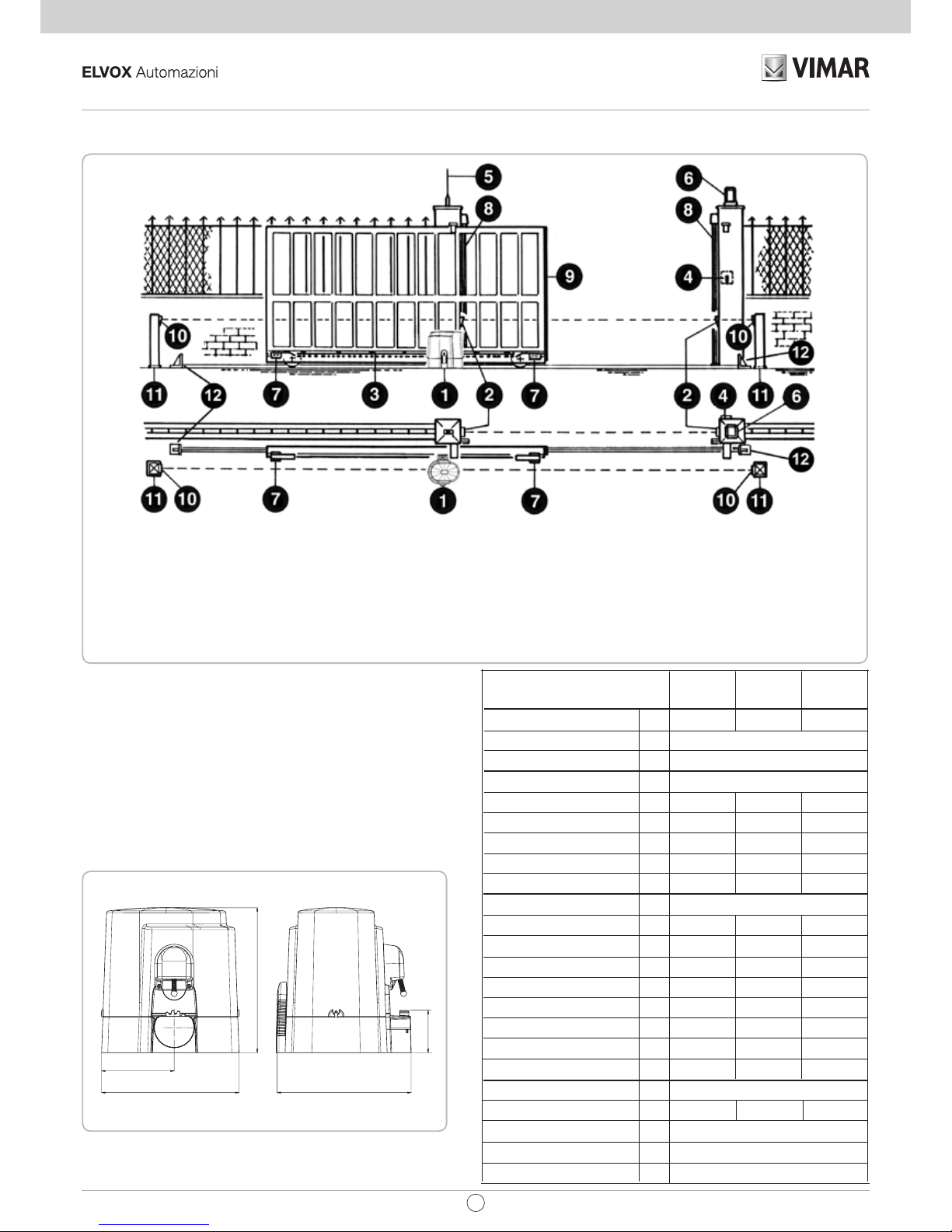
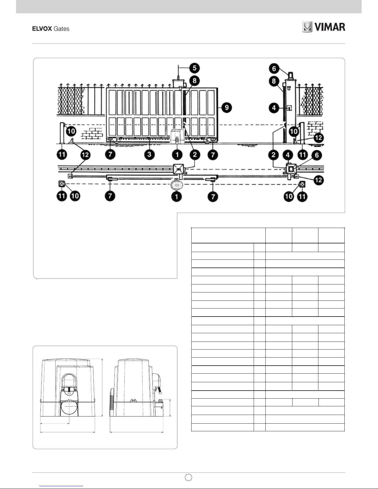
LAYOUT IMPIANTO
1 - Attuatore
2 - Fotocellule esterne
3 - Cremagliera Modulo 4
4 - Selettore a chiave
5 - Antenna radio
6 - Lampeggiatore
CARATTERISTICHE TECNICHE
Attuatori irreversibili per cancelli scorrevoli aventi un peso
massimo di 2200 kg.
L’irreversibilità di questo operatore fa si che il cancello non richieda
alcun tipo di serratura elettrica per un’efficace chiusura.
Il motore è protetto da una sonda termica che in caso di utilizzo
prolungato interrompe momentaneamente il movimento.
Misure in mm
1
800 1400 2200
0,155/0,18
4
230 V~ 50/60 Hz
600 790 1150
20,4 27 39
287/262 257/314 247/311
1,38/1,19 1,18/1,44 1,1/1,62
12,5 12,5 16
120 V~ 60 Hz
514 880 1175
17,5 30 40
242 322 295
2,15 2,9 2,85
80 60 60
300 400 500
60 % 60 % 60 %
8/6m 15/10m 15/10m
COMLUBE LHITGREASE EP/GR.2
10,5 12,3 14
<70
-10 ÷ +55 °C
44
CARATTERISTICHE
TECNICHE
Peso max cancello
Velocità di traino
Cremagliera modulo
Alimentazione e frequenza
Forza di spinta a giri costanti
Coppia max
Potenza motore
Assorbimento
Condensatore
Alimentazione e frequenza
Forza di spinta a giri costanti
Coppia max
Potenza motore
Assorbimento
Condensatore
Cicli consigliati al giorno
Servizio
Cicli consecutivi garantiti
Lubrificazione a grasso
Peso max
Rumorosità
Temperatura di lavoro
Grado di protezione
kg
m/s.
N
Nm
W
A
µF
N
Nm
W
A
µF
n°
n°
kg
db
°C
IP
ACTO ACTO ACTO
800A 1400A 2200A
93
160
303
296
320
7 - Staffe finecorsa (camme)
8 - Bordo sensibile
9 - Bordo sensibile
10 - Fotocellule interne
11 - Colonnine per fotocellule
12 - Fermi meccanici
IT
Page 3
1
ACTO: ESM4/ESM4.120 - ESM5/ESM.120 - ESM6/ESM6.120
CONTROLLO PRE-INSTALLAZIONE
- IL CANCELLO DEVE MUOVERSI SENZA ATTRITI -
N.B. È obbligatorio uniformare le caratteristiche del cancello alle norme
e leggi vigenti. Il cancello può essere automatizzato solo se in buono
stato e se rispondente alla norma EN 12604.
- L’anta non deve presentare porte pedonali. In caso contrario occorrerà
prendere opportune precauzioni in accordo al punto 5.4.1 della
EN12453 (ad esempio impedire il movimento del motore quando il
portoncino è aperto, grazie ad un microinterruttore opportunamente
collegato in centralina).
- Non bisogna generare punti di intrappolamento (ad esempio tra anta
aperta del cancello e cancellata).
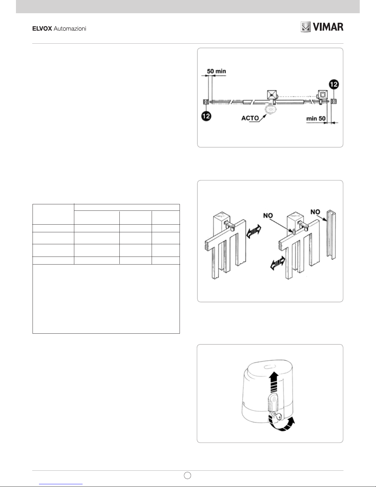
- Oltre ai finecorsa presenti nell’unità, è necessario che a ciascuna delle
due posizioni estreme della corsa sia presente un fermo meccanico
fisso che arresti il cancello nel caso di malfunzionamento dei finecorsa.
A tal fine il fermo meccanico deve essere dimensionato per sopportare
la spinta statica del motore più l’energia cinetica del cancello (12) (2).
- Le colonne del cancello devono avere superiormente delle guide
antideragliamento (3) per evitare involontari sganciamenti.
N.B.: Eliminare fermi meccanici del tipo descritto in figura 3.
Non devono essere presenti fermi meccanici al di sopra del cancello
perché non sono sufficientemente sicuri.
SBLOCCO
Da effettuare dopo aver tolto l’alimentazione elettrica al motore.
Per poter agire manualmente sul cancello è sufficiente inserire l’apposita
chiave e ruotarla 3 volte in senso antiorario (4).
Per poter eseguire in modo sicuro la movimentazione manuale dell’anta
occorre verificare che:
- sull’anta siano presenti maniglie idonee;
- tali maniglie siano posizionate in modo da non creare punti di pericolo
durante il loro utilizzo;
- lo sforzo manuale per muovere l’anta non superi i 225 N per i cancelli
posti su siti privati ed i 390 N per i cancelli posti su siti commerciali ed
industriali (valori indicati nel punto 5.3.5 della norma EN 12453).
2
3
4
TIPO DI COMANDO USO DELLA CHIUSURA
Persone esperte Persone esperte Uso illimitato
(fuori da area pubblica*) (area pubblica)
a uomo presente A B non possibile
a impulsi in vista
C o E C o E C e D, o E
(es. sensore)
a impulsi non in vista
C o E C e D, o E C e D, o E
(es. telecomando)
automatico C e D, o E C e D, o E C e D, o E
* esempio tipico sono le chiusure che non accedono a pubblica via.
A: Pulsante di comando a uomo presente (cioè ad azione mantenuta).
B: Selettore a chiave a uomo presente, come cod. EDS1.
C: Regolazione della forza del motore.
D: Bordi sensibili ZX01/EN e/o altri dispositivi di limitazione delle forze entro i limiti
della norma EN12453 - Appendice A.
E: Fotocellule, es. cod. EFA1 (Da applicare ogni 60÷70 cm per tutta l’altezza della
colonna del cancello fino ad un massimo di 2,5m - EN 12445 punto 7.3.2.1)
Componenti da installare secondo la norma EN12453
IT
Page 4
2
ACTO: ESM4/ESM4.120 - ESM5/ESM.120 - ESM6/ESM6.120
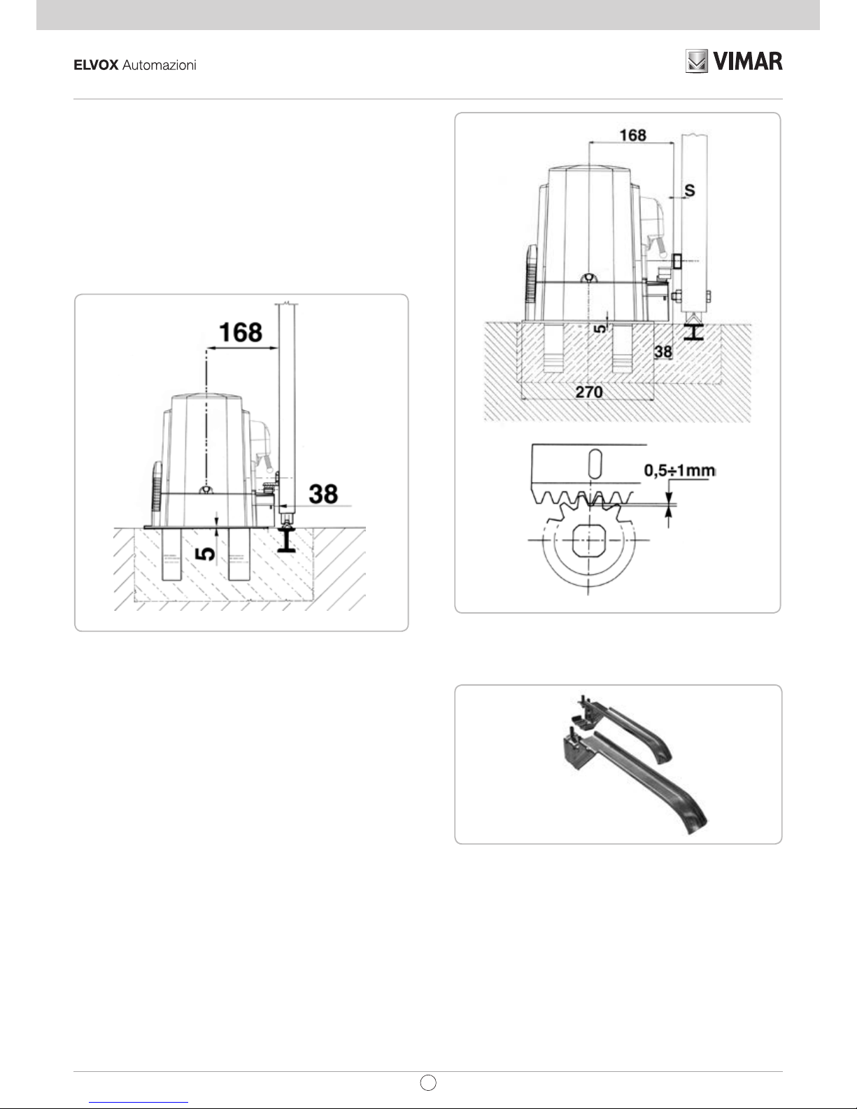
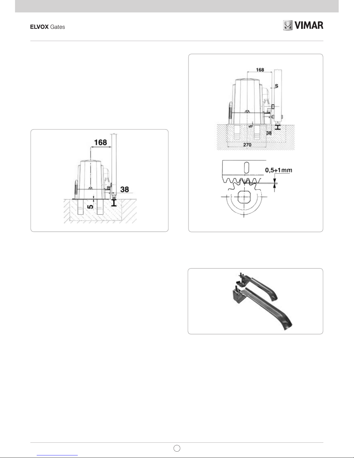
FISSAGGIO MOTORE E CREMAGLIERA
La cremagliera deve essere fissata a una certa altezza rispetto
all’appoggio del motore.
Questa altezza può essere variata grazie a delle asole presenti sulla
cremagliera.
La registrazione in altezza viene fatta affinché il cancello, durante il
movimento, non si appoggi sull’ingranaggio di trazione dell’attuatore
(5 e 6).
Per fissare la cremagliera sul cancello eseguire dei fori di Ø 5 mm e
filettarli utilizzando un maschio del tipo M6.
L’ingranaggio di traino deve avere circa 1 mm di agio rispetto alla
cremagliera.
FISSAGGIO FINECORSA
Per determinare la corsa della parte mobile si devono posizionare
due camme alle estremità della cremagliera (7).
La regolazione della corsa di apertura e chiusura, si ottiene spostando
le medesime sui denti della cremagliera.
Per bloccare le camme alla cremagliera avvitare a fondo le viti in
dotazione.
N.B: Oltre alle camme di fermo elettrico sopraesposte è obbligatoria
l’installazione di fermi meccanici robusti che non permettono la
fuori uscita del cancello dalle guide superiori.
MANUTENZIONE
Da effettuare solamente da parte di personale specializzato dopo
aver tolto l’alimentazione elettrica al motore.
Pulire periodicamente, a cancello fermo, la guida di scorrimento da
sassi e altra sporcizia.
7
5
6
Misure in mm
Misure in mm
IT
Page 5
3
ACTO: ESM4/ESM4.120 - ESM5/ESM.120 - ESM6/ESM6.120
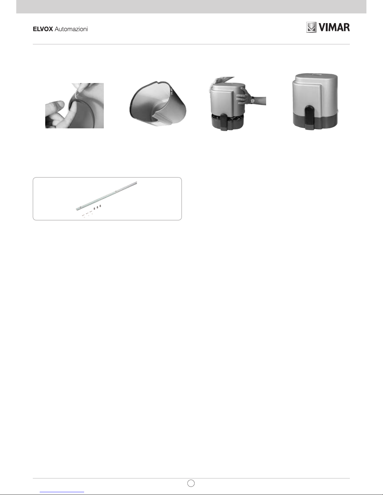
Applicare la guarnizione
Guarnizione applicata
Motore pronto
Chiudere il carter
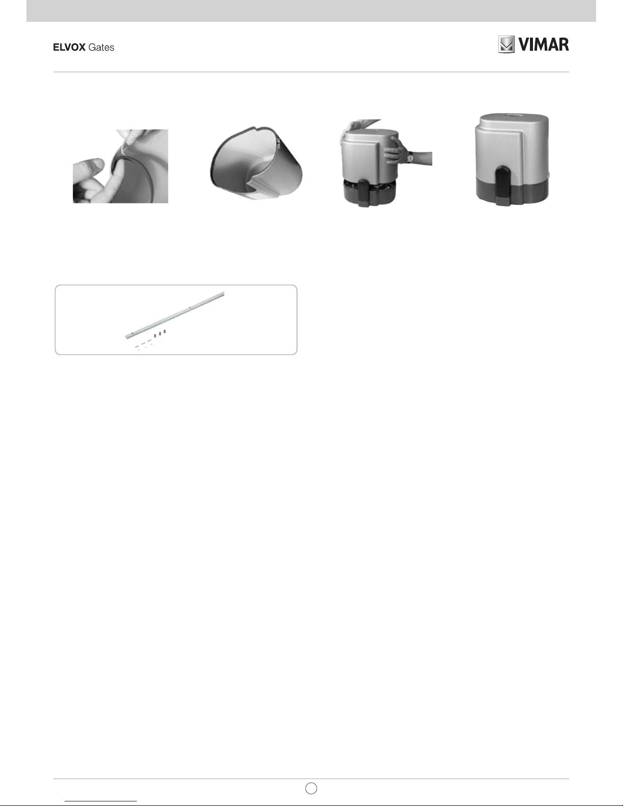
OPERAZIONE FINALE - La guarnizione deve essere applicata solo al termine dell’installazione, prima di rimontare il carter.
OPTIONAL
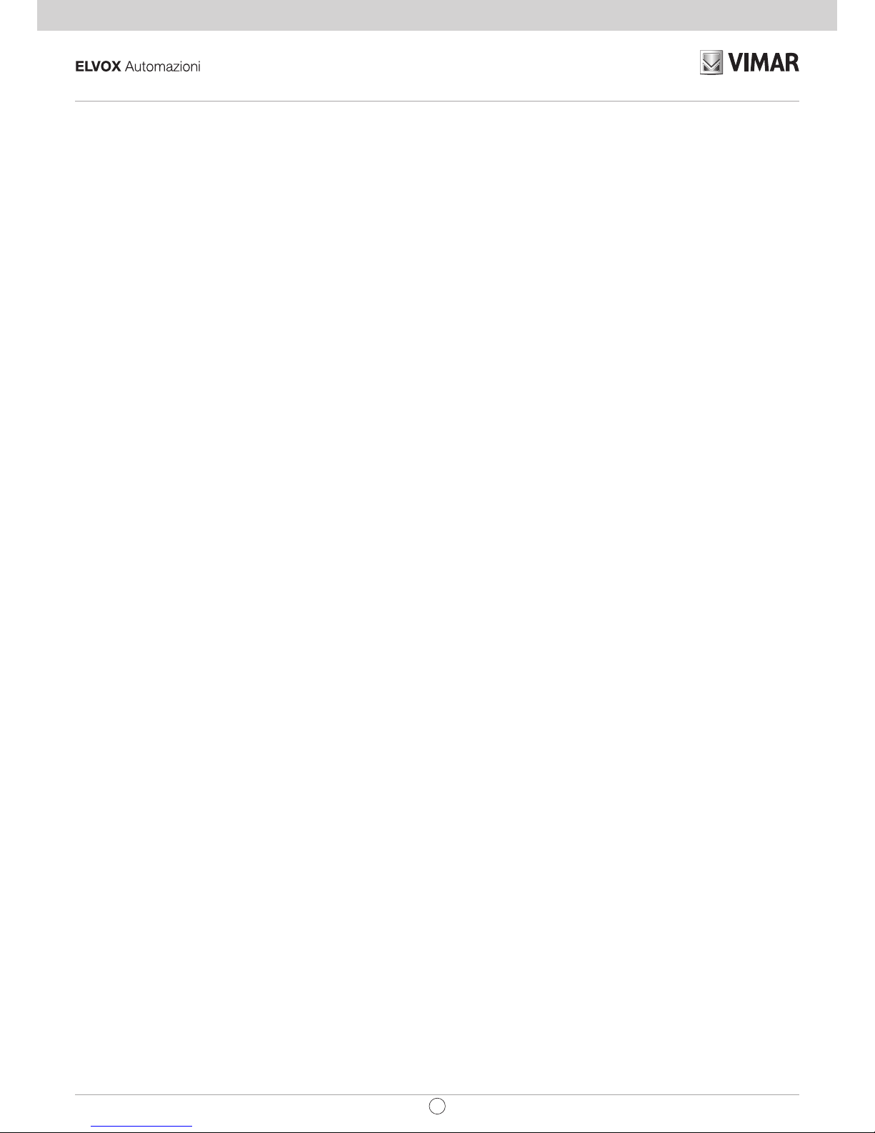
CREMAGLIERA MOD. 4
Ideale per cancelli con peso fino a 2200 kg. cod. ZE07
IT
Page 6
4
ACTO: ESM4/ESM4.120 - ESM5/ESM.120 - ESM6/ESM6.120
DICHIARAZIONE CE DI CONFORMITA’
(Dichiarazione di incorporazione di quasi-macchine allegato IIB Direttiva 2006/42/CE)
No. : ZDT00433.00
Il sottoscritto, rappresentante il seguente costruttore
Elvox SpA
Via Pontarola, 14/a
35011 Campodarsego PD - Italy
dichiara qui di seguito che i prodotti
ATTUATORI PER CANCELLI AD ANTE SCORREVOLI - SERIE ACTO
Articoli
ACTO 500A, ACTO 800A, ACTO 1400A, ACTO 2200A
risultano in conformità a quanto previsto dalla(e) seguente(i) direttiva(e) comunitaria(e) (comprese tutte le modifiche
applicabili) e che sono state applicate tutte le seguenti norme e/o specifiche tecniche:
Direttiva BT 2006/95/CE: EN 60335-2-103 (2003) + A11 (2009)
Direttiva EMC 2004/108/CE: EN 61000-6-1 (2007), EN 61000-6-3 (2007) + A1 (2011)
EN 61000-6-2 (2005), EN 61000-6-4 (2007) + A1 (2011)
Direttiva R&TTE 1999/5/CE: EN 301 489-3 (2002), EN 300 220-3 (2000)
Direttiva Macchine 2006/42/CE EN 13241 (2003) + A1 (2011), EN 12453 (2000)
Dichiara inoltre che la messa in servizio del prodotto non deve avvenire prima che la macchina finale, in cui deve essere
incorporato, non è stata dichiarata conforme, se del caso, alle disposizioni della Direttiva 2006/42/CE.
Dichiara che la documentazione tecnica pertinente è stata costituita da Elvox SpA, è stata compilata in conformità
all’allegato VIIB della Direttiva 2006/42/CE e che sono stati rispettati i seguenti requisiti essenziali: 1.1.1, 1.1.2, 1.1.3,
1.1.5, 1.1.6, 1.2.1, 1.2.2, 1.2.6, 1.3.1, 1.3.2, 1.3.3, 1.3.4, 1.3.7, 1.3.8, 1.3.9, 1.4.1, 1.4.2, 1.5.1, 1.5.2, 1.5.4, 1.5.5, 1.5.6,
1.5.7, 1.5.8, 1.5.9, 1.6.1., 1.6.2, 1.7.1, 1.7.2, 1.7.3, 1.7.4.
Si impegna a presentare, in risposta ad una richiesta adeguatamente motivata delle autorità nazionali, tutta la
necessaria documentazione giustificativa pertinente al prodotto.
Campodarsego, 19/04/2013
L’Amministratore Delegato
Nota: Il contenuto di questa dichiarazione corrisponde a quanto dichiarato nell’ultima revisione della dichiarazione ufficiale disponibile
prima della stampa di questo manuale. Il presente testo è stato adattato per motivi editoriali. Copia della dichiarazione originale può essere
richiesta a Elvox SpA
IT
Page 7
5
ACTO: ESM4/ESM4.120 - ESM5/ESM.120 - ESM6/ESM6.120
SYSTEM LAY-OUT
1 - operating device
2 - External photocells
3 - Rack of Module 4
4 - Key selector
5 - Radio antenna
6 - Blinker
7 - Limit switch plate (cams)
8 - Safety strip
9 - Safety strip
10 - Internal Photocells
11 - Photocell columns
12 - Mechanical stops
TECHNICAL FEATURES
Irreversible operating devices for sliding gates with a maximum
weight of 2.200 kg / 4900 lbs.
The irreversibility of this operating device allows you to avoid using any
electric lock for an effective closing of the gate. The motor is protected
by an heat probe, that temporary interrupts the operating cycle in case
of prolonged use.
1
800 1400 2200
0,155/0,18
4
230 V~ 50/60 Hz
600 790 1150
20,4 27 39
287/262 257/314 247/311
1,38/1,19 1,18/1,44 1,1/1,62
12,5 12,5 16
120 V~ 60 Hz
514 880 1175
17,5 30 40
242 322 295
2,15 2,9 2,85
80 60 60
300 400 500
60 % 60 % 60 %
8/6m 15/10m 15/10m
COMLUBE LHITGREASE EP/GR.2
10,5 12,3 14
<70
-10 ÷ +55 °C
44
TECHNICAL
DATA
Max. leaf weight
Operating speed
Rack
EEC Power supply
Thrust force to constant turns
Max. torque
Motor power
Absorbed current
Capacitor
Power supply
Thrust force to constant turns
Max. torque
Motor power
Absorbed current
Capacitor
Daily operations suggested
Service
Guaranteed consecutive cycles
Grease
Weight of electroreducer
Noise
Working temperature
Protection
kg
m/s.
N
Nm
W
A
µF
N
Nm
W
A
µF
n°
n°
kg
db
°C
IP
ACTO ACTO ACTO
800A 1400A 2200A
/Measurements in mm
93
160
303
296
320
EN
Page 8

6
ACTO: ESM4/ESM4.120 - ESM5/ESM.120 - ESM6/ESM6.120
CHECKING BEFORE THE INSTALLATION
!! THE GATE SHALL MOVE FRICTIONLESS !!
N.B.: Gate features must be uniformed with the standards and laws in
force. The door/gate can be automated only if it is in a good condition
and its conditions comply with the EN 12604 norm.
- The door/gate leaf does not have a pedestrian door. In the opposite
case it is necessary to take the appropriate steps, in accordance with
EN 12453 norm (for instance; by preventing the operation of the motor
when the pedestrian door is opened, by installing a safety microswitch
connected with the control panel).
- Besides the electrical or mechanical limit switches available on the
operators, there must be, on both ends of the installation, a fixed
mechanical stopper which stop the gate in the unlikely event of ill
functioning of limit swithces on the operators. For this reason the fixed
mechanical stopper must be of an adeguate size to withstand the static
and kinetic forces generated by the gate (12) (2).
- Gate columns shall have anti-derailment guides on their top (3), to
avoid the unintentional gate release.
N.B.: Remove mechanical stops like the one in fig. 3.
No mechanical stops shall be on top of the gate, since these mechanical
stops are not safe enough.
RELEASE
To operated after the power supply to the motor has been
interrupted.
In order to work manually on the gate, you just need to insert the fitting
key and rotate it 3 times counterclockwise (4).
In order to carry out the manual operation of the gate leaf the followings
must be checked:
- That the gate is endowed with appropriate handles;
- That these appropriate handles are placed so to avoid safety risks for
the operator;
- That the physical effort necessary to move the gate leaf should not be
higher than 225 N, for doors/gates for private dwellings, and, 390 N
for doors/gates for commercial and industrial sites ( values indicated
in 5.3.5 of the EN 12453 norm) .
2
3
4
COMMAND TYPE USE OF THE SHUTTER
Skilled persons Skilled persons
Unrestricted use
(out of public area*) (public area)
with manned operation A B non possibile
with visible impulses
C or E C or E C and D, or E
(e.g. sensor)
with not visible impulses
C or E C and D, or E C and D, or E
(e.g. remote controldevice)
automatic C and D, or E C and D, or E C and D, or E
* a typical example are those shutters which do not have access to any public way.
A: Command button with manned operation (that is, operating as long as activated).
B: Key selector with manned operation, like code EDS1.
C: Adjustable power of the motor.
D: Safety strip ZX01/EN and/or other safety devices to keep thrust force within the limits of
EN12453 regulation - Appendix A.
E: Photocells, like code EFA1 (To apply every 60÷70 cm for all the height of the column of the
gate up to a maximum of 2,5m - EN 12445 point 7.3.2.1).
Parts to install meeting the EN 12453 standard
EN
Page 9
7
ACTO: ESM4/ESM4.120 - ESM5/ESM.120 - ESM6/ESM6.120
MOTOR AND RACK FITTING
The rack shall be fitted over the motor support, at a certain distance
from It. Its height can be adjusted thanks to the holes In the rack.
The height adjusting is necessary to prevent the gate leaning on the
driving gear (5 and 6).
To fix the rack on the gate, drill some Ø 5 mm holes and thread them
using an M6 screw tap.
The driving gear needs some 1 mm clearance from the rack.
LIMIT SWITCH FITTING
In order to determine the gate travel length, place two cams at the
ends of the rack (7).
Move the cams on the rack teeth to adjust their opening and closing
travel.
To fix the cams to the rack, tighten the screws issued.
N.B: In addition to the electric stop cams mentioned above, you must
also install strong mechanical stops preventing the gate from
sliding out from the top guides.
MAINTENANCE
To be carried out exclusively by skilled persons after the power
supply to the motor has been interrupted.
Periodically, when the gate is standstill, clean and keep the guide free
from stones and dirt.
7
5
Measurements in mm/inch
6,6”
1,5”
4,86”
0,2”
6
6,6”
1,5”
0,2”
10,6”
0,04”
Measurements in mm/inch
EN
Page 10
8
ACTO: ESM4/ESM4.120 - ESM5/ESM.120 - ESM6/ESM6.120
ACCESSORIES -
For the connections and the technical data of the optional equipments follow the relevant handbooks.
RACK OF MODEL 4
Ideal for gates weighting up to 2200 kg / 4,800 lbs. code ZE07
EN
Fit the gasket
The gasket is fitted
Motor ready
Close the case
FINAL OPERATION - The gasket shall be fitted only at the end of the installation, before you mount the case.
Page 11

9
ACTO: ESM4/ESM4.120 - ESM5/ESM.120 - ESM6/ESM6.120
EC DECLARATION OF CONFORMITY
(Declaration of incorporation of partly completed machinery annex IIB Directive 2006/42/EC)
No. : ZDT00433.00
The undersigned, representing the following manufacturer
Elvox SpA
Via Pontarola, 14/a
35011 Campodarsego PD - Italy
herewith declares that the products
ACTUATORS FOR GATES WITH SLIDING DOORS - SERIES ACTO
Articles
ACTO 500A, ACTO 800A, ACTO 1400A, ACTO 2200A
are in conformity with the provisions of the following EC directive(s) (including all applicable amendments) and that the
following standards and/or technical specifications have been applied:
LV Directive 2006/95/EC: EN 60335-2-103 (2003) + A11 (2009)
EMC Directive 2004/108/EC: EN 61000-6-1 (2007), EN 61000-6-3 (2007) + A1 (2011),
EN 61000-6-2 (2005), EN 61000-6-4 (2007) + A1 (2011)
R&TTE Directive 1999/5/EC: EN 301 489-3 (2002), EN 300 220-3 (2000)
Machinery Directive 2006/42/EC EN 13241 (2003) + A1 (2011), EN 12453 (2000)
Further hereby declares that the product must not be put into service until the final machinery into which it is to be
incorporated has been declared in conformity with the provisions of Directive 2006/42/EC, where appropriate.
Declares that the relevant technical documentation has been compiled by Elvox SpA in accordance with part B of Annex
VII of Directive 2006/42/EC and that the following essential requirements of this Directive have been applied and fulfilled:
1.1.1, 1.1.2, 1.1.3, 1.1.5, 1.1.6, 1.2.1, 1.2.2, 1.2.6, 1.3.1, 1.3.2, 1.3.3, 1.3.4, 1.3.7, 1.3.8, 1.3.9, 1.4.1, 1.4.2, 1.5.1, 1.5.2,
1.5.4, 1.5.5, 1.5.6, 1.5.7, 1.5.8, 1.5.9, 1.6.1., 1.6.2, 1.7.1, 1.7.2, 1.7.3, 1.7.4.
I undertake to make available, in response to a reasoned request by the national authorities, any further supporting
product documents they require.
Campodarsego, 19/04/2013
The Managing Director
Note: The contents of this declaration correspond to what declared in the last revision of the official declaration available before printing
this manual. The text herein has been re-edited for editorial purposes. A copy of the original declaration can be requested to Elvox SpA
EN
Page 12

10
ACTO: ESM4/ESM4.120 - ESM5/ESM.120 - ESM6/ESM6.120
SCHÉMA DÉTAILLÉ DE L’INSTALLATION
1 - Opérateur
2 - Photocellules extérieures
3 - Crémaillère Module 4
4 - Sélecteur à clé
5 - Antenne radio
6 - Feu clignotant
CARACTÉRISTIQUES TECHNIQUES
Opérateurs irréversibles pour portails coulissants dont le poids
maximal est de 2200 kg.
Grâce à l’irréversibilité de cet opérateur, le portail ne nécessite aucun
type de serrure électrique pour une fermeture efficace.
Le moteur est protégé par une sonde thermique, qui interrompt
momentanément le mouvement en cas de non-utilisation prolongée.
Mesures en mm
1
800 1400 2200
0,155/0,18
4
230 V~ 50/60 Hz
600 790 1150
20,4 27 39
287/262 257/314 247/311
1,38/1,19 1,18/1,44 1,1/1,62
12,5 12,5 16
120 V~ 60 Hz
514 880 1175
17,5 30 40
242 322 295
2,15 2,9 2,85
80 60 60
300 400 500
60 % 60 % 60 %
8/6m 15/10m 15/10m
COMLUBE LHITGREASE EP/GR.2
10,5 12,3 14
<70
-10 ÷ +55 °C
44
CARACTERISTIQUES
TECHNIQUES
Poids maxi du portail
Vitesse de traction
Module crémaillère
EEC
Alimentation et frequence
Force maxi de poussée
Couple max
Puissance moteur
Absorption courant
Condensateur
Alimentation et frequence
Force maxi de poussée
Couple max
Puissance moteur
Absorption courant
Condensateur
Cycles conseillés par jour
Service
Cycles consécutifs garantis
Type d’huile
Poids maximum
Bruit
Temperature de travail
Indìce de protection
kg
m/s.
N
Nm
W
A
µF
N
Nm
W
A
µF
n°
n°
kg
db
°C
IP
ACTO ACTO ACTO
800A 1400A 2200A
93
160
303
296
320
FR
7 - Limiteurs de course (cames)
8 - Barre palpeuse
9 - Barre palpeuse
10 - Photocellules intérieures
11 - Potelets de support pour photocellules
12 - Arrêts mécaniques
Page 13

11
ACTO: ESM4/ESM4.120 - ESM5/ESM.120 - ESM6/ESM6.120
CONTRÔLE PRÉ-INSTALLATION
!! LE PORTAIL DOIT SE DÉPLACER SANS FROTTER !!
N.B. Il est impératif d’uniformiser les caractéristiques du portail avec
les normes et les lois en vigueur. La portail peut être automatisée
seulement si elle est en bon état et qu’elle est conforme à la norme
EN 12604.
- Le vantail ne doit pas comporter de portillon intégré. Dans le cas
contraire, il sera opportun de prendre les précautions décrites au point
5.4.1 de la EN 12453 (interdire, par le biais d’un contact raccordé aux
bornes adaptées de la platine électronique, la mise en marche de
l’automatisme si le portillon est ouvert).
- Ne pas générer de zone d’écrasement (par exemple entre le vantail
ouvert et la cloture).
- Outre les fins de course présents sur l’opérateur, il est nécessaire
d’installer des butées mécaniques fixes à l’extrémité de chaque course
de sorte à arrêter le portail en cas de dysfonctionnement des fins de
course électriques. Pour cela, les butées mécaniques doivent être
dimensionnées de sorte à supporter la poussée statique du moteur
ajoutée à l’énergie cinétique du portail (12) (2).
- Les poteaux du portail doivent avoir des glissières anti-déraillement
sur la partie supérieure (3), afin d’éviter tout décrochage accidentel.
N.B.: Éliminer les arrêts mécaniques du type indiqué, décrit dans la
figure 3.
Il ne devra y avoir aucun arrêt mécanique au-dessus du portail, étant
donné que les arrêts mécaniques ne sont pas suffisamment sûrs.
DÉBLOCAGE
Cette opération ne devra être effectuée qu’après avoir mis le
moteur hors-tension.
Afin de pouvoir agir manuellement sur le portail, il suffit d’introduire
la clé, destinée à cet effet, et de la faire tourner 3 fois dans le sens
contraire à celui des aiguilles d’une montre (4).
Afin de pouvoir manœuvre manuellement le vantail, il est important de
vérifier que :
- il soit fourni des poignées adaptées sur le vantail;
- ces poignées doivent être positionnées de sorte à ne pas créer un
danger durant leur utilisation;
- l’effort manuel pour mettre en mouvement le vantail ne doit pas
excéder 225 N pour les portes et portails en usage privé, et 390 N
pour les portes et portails à usage industriel et commercial (valeurs
indiquées au paragraphe 5.3.5 de la norme EN 12453).
2
3
4
TYPE DE COMMANDE USAGE DE LA FERMETURE
Personne expertes Personne expertes Usage illimité
(au dehors d’une zone publique*)
(zone publique)
homme presente A B non possible
impulsion en vue
C ou E C ou E C et D, ou E
(es. capteur)
impulsion hors de vue
C ou E C et D, ou E C et D, ou E
(es. boîtier de commande)
automatique C et D, ou E C et D, ou E C et D, ou E
* example typique: fermetures qui n’ont pas d’accès à un chemin public.
A: Touche de commande à homme present (à action maintenue).
B: Sélecteur à clef à homme mort, code EDS1.
C: Réglage de la puissance du moteur.
D: Barre palpeuse ZX01/EN et/ou autres dispositifs de limitation des forces dans les
limites de la norme EN12453- appendice A.
E: Cellules photo-électriques, code EFA1 (Appliquer chaque 60÷70 cm pour toute
la taille de la colonne de la porte jusqu’à un maximum de 2,5m - EN 12445 point
7.3.2.1).
Parties à installer conformément à la norme EN12453
FR
Page 14

12
ACTO: ESM4/ESM4.120 - ESM5/ESM.120 - ESM6/ESM6.120
FIXATION MOTEUR ET CRÉMAILLÈRE
La crémaillère doit être fixée à une certaine hauteur par rapport au
support du moteur.
Cette hauteur peut être modifiée, grâce aux boutonnières présentes
sur la crémaillère.
Le réglage en hauteur est effectué afin que, lors du mouvement, le
portail ne puisse appuyer sur l’engrenage de traction du opérateur (5
et 6). Pour fixer la crémaillère sur le portail, il suffit de faire des trous
de Ø 5 mm et de les tarauder en se servant d’un taraud du type M6.
L’engrenage d’entraînement doit disposer d’environ 1 mm de rayon
d’action par rapport à la crémaillère.
FIXATION FIN DE COURSE
Pour déterminer la course de la partie mobile, il faut positionner
deux cames sur les extrémités de la crémaillère (7).
Pour procéder au réglage de la course d’ouverture et de fermeture,
il suffit de déplacer les cames sur les crans de la crémaillère. Pour
bloquer les cames sur la crémaillère, visser à fond les vis, fournies
avec l’équipement.
N.B: En plus des cames d’arrêt électrique susmentionnées, il est
indispensable d’installer des arrêts mécaniques solides, qui
empêcheront le portail de sortir des glissières supérieures.
ENTRETIEN
Toutes les opérations d’entretien devront être effectuées
exclusivement par du personnel spécialisé et après avoir mis le
moteur hors-tension.
Nettoyer périodiquement la glissière en enlevant tous les cailloux ou
toute autre saleté qui pourraient s’y trouver. Cette opération doit être
effectuée lorsque le portail est arrêté.
7
5
6
Mesures en mm
Mesures en mm
Page 15

13
ACTO: ESM4/ESM4.120 - ESM5/ESM.120 - ESM6/ESM6.120
CRÉMAILLÈRE MOD. 4
Idéal pour les portails jusqu’à 2200 kg. code ZE07
OPTIONS - Pour les branchements et les données techniques des accessoires, se conformer aux livrets d’instruction correspondants.
FR
FR
Appliquer la garniture
Garniture appliquée
Moteur prêt
Refermer le carter
OPÉRATION FINALE - La garniture ne devra être appliquée qu’après avoir terminé l’installation, avant de remonter le carter.
FR
Page 16

14
ACTO: ESM4/ESM4.120 - ESM5/ESM.120 - ESM6/ESM6.120
DÉCLARATION DE CONFORMITÉ
(Déclaration d’intégration de quasi-machines annexe IIB Directive 2006/42/CE)
n° : ZDT00433.00
Je soussigné, représentant le fabricant
Elvox SpA
Via Pontarola, 14/a
35011 Campodarsego (PD) Italy
déclare ci-dessous que les produits
ACTUATEURS POUR PORTAILS À VANTAUX COULISSANTS - SÉRIE ACTO
Articles
ACTO 500A, ACTO 800A, ACTO 1400A, ACTO 2200A
sont conformes aux directives communautaires suivantes (ainsi qu’à l’ensemble de leurs modifications applicables) et
qu’ils
respectent les normes et les spécifications techniques ci-dessous:
Directive BT 2006/95/CE: EN 60335-2-103 (2003) + A11 (2009)
Directive EMC 2004/108/CE: EN 61000-6-1 (2007), EN 61000-6-3 (2007) + A1 (2011)
EN 61000-6-2 (2005), EN 61000-6-4 (2007) + A1 (2011)
Directive R&TTE 1999/5/CE: EN 301 489-3 (2002), EN 300 220-3 (2000)
Directive machine 2006/42/CE EN 13241 (2003) + A1 (2011), EN 12453 (2000)
déclare en outre que l’actionneur ne doit pas être mis en service avant que la machine finale à laquelle il sera intégré
n’ait été déclarée conforme, si nécessaire, à la Directive 2006/42/CE ;
déclare que la documentation technique correspondante a été rédigée par Elvox SpA conformément à l’annexe VIIB de
la Directive 2006/42/CE dont elle respecte les dispositions essentielles suivantes: 1.1.1, 1.1.2, 1.1.3, 1.1.5, 1.1.6, 1.2.1,
1.2.2, 1.2.6, 1.3.1, 1.3.2, 1.3.3, 1.3.4, 1.3.7, 1.3.8, 1.3.9, 1.4.1, 1.4.2, 1.5.1, 1.5.2, 1.5.4, 1.5.5, 1.5.6, 1.5.7, 1.5.8, 1.5.9,
1.6.1., 1.6.2, 1.7.1, 1.7.2, 1.7.3, 1.7.4.
Il s’engage à présenter en réponse à toute demande motivée des autorités nationales le dossier justificatif de l’appareil.
Campodarsego, 19/04/2013
Le Directeur Général
Remarque: Cette déclaration correspond à la dernière révision de la déclaration officielle disponible avant l’impression de ce manuel.
Ce texte a été adapté aux nécessités éditoriales. Une copie de la déclaration originale peut être demandée à Elvox SpA.
FR
Page 17

15
ACTO: ESM4/ESM4.120 - ESM5/ESM.120 - ESM6/ESM6.120
DISPOSICIÒN DE LA INSTALACIÒN
1 - Operador
2 - Fotocélulas externas
3 - Cremallera Módulo 4
4 - Interruptor de llave
5 - Antena de radio
6 - Intermitente
CARACTERÍSTICAS TÉCNICAS
Operadores irreversibles para verjas correderas con un peso
máximo de 2200 kg.
La irreversibilidad de este operador permite que la verja no requiera
ningún tipo de cerradura eléctrica para un cierre eficaz.
El motor está protegido por una sonda térmica que en caso de uso
prolongado interrumpe momentáneamente el movimiento.
Medidas en mm
1
800 1400 2200
0,155/0,18
4
230 V~ 50/60 Hz
600 790 1150
20,4 27 39
287/262 257/314 247/311
1,38/1,19 1,18/1,44 1,1/1,62
12,5 12,5 16
120 V~ 60 Hz
514 880 1175
17,5 30 40
242 322 295
2,15 2,9 2,85
80 60 60
300 400 500
60 % 60 % 60 %
8/6m 15/10m 15/10m
COMLUBE LHITGREASE EP/GR.2
10,5 12,3 14
<70
-10 ÷ +55 °C
44
CARACTERÍSTICAS
TÉCNICAS
Peso máx. verja
Velocidad de arrastre
Cremallera módulo
Alimentación y frecuencia
Fuerza a revoluciones constantes
Coppia máx.
Potencia motor
Absorción
Condensador
Alimentación y frecuencia
Fuerza a revoluciones constantes
Coppia máx.
Potencia motor
Absorción
Condensador
Ciclos diarios sugeridos
Servicio
Ciclos garantizados
Engrase
Peso máx.
Nivel de ruido
Temperatura de trabajo
Nivel de protección
kg
m/s.
N
Nm
W
A
µF
N
Nm
W
A
µF
n°
n°
kg
db
°C
IP
ACTO ACTO ACTO
800A 1400A 2200A
93
160
303
296
320
ES
7 - Limitadores de recorrido (leva)
8 - Nervadura mecánica
9 - Nervadura neumática o Fotonervadura
10 - Fotocélulas internas
11 - Columnas para las fotocélulas
12 - Topes mecánicos
Page 18

16
ACTO: ESM4/ESM4.120 - ESM5/ESM.120 - ESM6/ESM6.120
CONTROL PRE-INSTALACIÓN
¡¡LA VERJA TIENE QUE MOVERSE SIN ROCES!!
Es obligatorio uniformar las características de la verja a las normas y
leyes en vigor. La puerta puede ser automatizada sólo si se encuentra
en buen estado y responde a la norma EN 12604.
- La puerta no tiene que tener puertas peatonales. De lo contrario se
tendrán que tomar las oportunas precauciones de acuerdo con el
punto 5.4.1 de la EN12453 (por ejemplo impedir el movimiento del
motor cuando la puertecilla está abierta, gracias a un microinterruptor
debidamente conectado a la central).
- No hay que generar puntos en los que se pueda quedar atrapado (por
ejemplo entre la puerta de la cancela y la verja).
- Además de los finales de carrera presentes en la unidad, es necesario
que en cada una de las dos posiciones extremas del recorrido
haya un seguro mecánico fijo que pare la cancela en caso de mal
funcionamiento del final de carrera. Con este objetivo el seguro
mecánico tiene que ser dimensionado para poder resistir el empuje
estático del motor más la energía cinética de la cancela (12) (2).
- Las columnas de la verja tienen que llevar en su parte superior unas
guías anti-descarrilamiento (3) para evitar desenganches involuntarios.
N.B.: Eliminar los topes mecánicos del tipo descrito en el Figura 3.
No tiene que haber topes mecánicos por encima de la verja porque no
son suficientemente seguros.
DESBLOQUEO
A efectuar tras haber cortado la alimentación eléctrica al motor.
Para poder abrir manualmente la cancela, en el caso de que faltase la
corriente eléctrica, con introducir la llave y girarla 3 veces en sentido
opuesto a las agujas del reloj (4).
Para poder realizar en modo seguro el desplazamiento manual de la
puerta hay que controlar que:
- Las manillas de la puerta que se han proporcionado sean idóneas;
- Estas manillas no estén posicionadas en modo de crear puntos de
peligro durante su utilizo;
- El esfuerzo manual para mover la puerta no debe superar los 225
N para las cancelas colocadas en lugares privados y los 390 N para
las cancelas colocadas en sitios comerciales e industriales (valores
indiacados en el punto 5.3.5 de la norma EN 12453).
2
3
4
TYPO DE MANDO USO DEL CIERRE
Personas expertas Personas expertas Uso ilimitado
(fuera de un área pública*) (área pública)
en presencia de alguien A B non posivel
con impulsos a la vista
E E E
(ej. sensor)
con impulso no a la vista
E E E
(ej. telemando)
automatico E E E
*un ejemplo típico son los cierres que no dan a la calle.
A: Pulsador de mando en presencia de alguien, (es decir con acción mantenida).
B: Interruptor de llave en presencia de alguien, como cód. EDS1.
C: Regulacion de la fuerza del motor.
D: Nervaduras ZX01/EN y / o otros dispositivos que limitan las fuerzas entre limites
de las normas EN 12453 - Appendix A.
E: Fotocélulas, como cód. EFA1 (Aplicar cada 60÷70 cm por toda la altura de la
puerta hasta un máximo de 2,5 m (EN 12445 punto 7.3.2.1).
Componentes a instalar según la norma EN12453
ES
Page 19

17
ACTO: ESM4/ESM4.120 - ESM5/ESM.120 - ESM6/ESM6.120
ANCLAJE MOTOR Y CREMALLERA
La cremallera se tiene que anclar a una determinada altura respecto al
soporte del motor.
Dicha altura se puede variar gracias a unos ojales presentes en la
cremallera.
El ajuste de la altura se efectúa para que la verja durante el movimiento
no se apoye sobre el engranaje de tracción del operador (5,6).
Para fijar la cremallera a la verja se practican unos agujeros de ø 5mm
y se roscan usando una roscadora del tipo M6.
El engranaje de arrastre tiene que tener una holgura de alrededor de 1
mm respecto a la cremallera .
FIJACIÓN FINAL DE CARRERA
Para determinar el recorrido de la parte móvil se tiene que colocar
dos limitadores de recorrido en los extremos de la cremallera (7).
La regulación de la abertura y el cierre, se obtiene desplazando la
misma sobre los dientes de la cremallera.
Para fijar las limitadores de tope de recorrido a la verja, atornillar a
fondo los tornillos suministrados.
N.B.: además de los citados limitadores de recorrido eléctricos
es obligatorio instalar unos topes mecánicos resistentes que
impidan la salida del la verja de las guías superiores.
MANTENIMIENTO
Tiene que ser efectuado solamente por personal especializado
tras haber cortado la alimentación eléctrica al motor.
Limpiar periódicamente, con la verja parada, la guía de deslizamiento
de eventuales piedras u otras suciedades.
7
5
6
Medidas en mm
Medidas en mm
ES
Page 20

18
ACTO: ESM4/ESM4.120 - ESM5/ESM.120 - ESM6/ESM6.120
OPCIONALES - Para las conexiones y datos técnicos de los accesorios, consultar los manuales respectivos.
CREMALLERA MOD. 4
Ideal para cancelas con peso hasta 2200 kg. cód. ZE07
ES
Aplicar la junta
Junta aplicada
Motor preparado
Cerrar el cárter
OPERACIÓN FINALE - La junta se tiene que aplicar una vez acabada la instalación y antes de volver a colocar el cárter.
Page 21

19
ACTO: ESM4/ESM4.120 - ESM5/ESM.120 - ESM6/ESM6.120
DECLARACIÓN CE DE CONFORMIDAD
(Declaración de incorporación de cuasi máquinas anexo IIB Directiva 2006/42/CE)
N. : ZDT00433.00
El abajo firmante, representante del siguiente fabricante
Elvox SpA
Via Pontarola, 14/a
35011 Campodarsego (PD) Italy
declara que los productos
ACTUADORES PARA CANCELAS DE HOJAS CORREDERAS - SERIE ACTO
Artículos
ACTO 500A, ACTO 800A, ACTO 1400A, ACTO 2200A
son conformes a lo que establecen las siguientes directivas comunitarias (incluidas todas las modificaciones aplicables)
y que se han aplicado todas las siguientes normas y/o especificaciones técnicas:
Directiva BT 2006/95/CE: EN 60335-2-103 (2003) + A11 (2009)
Directiva EMC 2004/108/CE: EN 61000-6-1 (2007), EN 61000-6-3 (2007) + A1 (2011)
EN 61000-6-2 (2005), EN 61000-6-4 (2007) + A1 (2011)
Directiva R&TTE 1999/5/CE: EN 301 489-3 (2002), EN 300 220-3 (2000)
Directiva máquina 2006/42/CE EN 13241 (2003) + A1 (2011), EN 12453 (2000)
Además, declara que el producto no deberá ser puesto en servicio mientras la máquina final en la cual vaya a ser
incorporada no haya sido declarada conforme, si procede, a lo dispuesto en la Directiva 2006/42/CE.
Declara que la correspondiente documentación técnica ha sido elaborada por Elvox SpA, de conformidad con el anexo
VIIB de la Directiva 2006/42/CE y que se han cumplido los siguientes requisitos esenciales: 1.1.1, 1.1.2, 1.1.3, 1.1.5,
1.1.6, 1.2.1, 1.2.2, 1.2.6, 1.3.1, 1.3.2, 1.3.3, 1.3.4, 1.3.7, 1.3.8, 1.3.9, 1.4.1, 1.4.2, 1.5.1, 1.5.2, 1.5.4, 1.5.5, 1.5.6, 1.5.7,
1.5.8, 1.5.9, 1.6.1., 1.6.2, 1.7.1, 1.7.2, 1.7.3, 1.7.4.
Se compromete a transmitir, en respuesta a un requerimiento debidamente motivado de las autoridades nacionales,
toda la información pertinente relativa al producto.
Campodarsego, 19/04/2013
El Director Ejecutivo
Nota: El contenido de esta declaración corresponde a lo declarado en la última revisión de la declaración oficial disponible antes de
imprimir este manual. El presente texto ha sido adaptado por razones editoriales. Se puede solicitar a Elvox SpA la copia de la declaración
original.
ES
Page 22

20
ACTO: ESM4/ESM4.120 - ESM5/ESM.120 - ESM6/ESM6.120
ANLAGEN LAY-OUT
1 - Betriebsgerät
2 - Externe Fotozellen
3 - Zahnstange Modul 4
4 - Schlüsselwählschalter
5 - Radioantenne
6 - Blinkleuchte
TECHNISCHE EIGENSCHAFTEN
Irreversible Betriebsgeräte für Schiebetore mit einem
Maximalgewicht von 2200 kg.
Durch die Irreversibilität dieses Betriebsgeräts benötigt das Tor zur
wirkungsvollen Verriegelung kein elektrisches Sicherheitsschloss.
Der Motor wird durch eine thermische Sonde geschützt, die im Fall
eines langen Einsatzes momentan die Bewegung unterbricht.
Abmessungen in mm
800 1400 2200
0,155/0,18
4
230 V~ 50/60 Hz
600 790 1150
20,4 27 39
287/262 257/314 247/311
1,38/1,19 1,18/1,44 1,1/1,62
12,5 12,5 16
120 V~ 60 Hz
514 880 1175
17,5 30 40
242 322 295
2,15 2,9 2,85
80 60 60
300 400 500
60 % 60 % 60 %
8/6m 15/10m 15/10m
COMLUBE LHITGREASE EP/GR.2
10,5 12,3 14
<70
-10 ÷ +55 °C
44
TECHNISCHE
EIGENSCHAFTEN
Max. Torgewicht
Laufgeschwindigkeit
Zahnstange Modul
Stromspannung und frequenz
Max. Schubkraft
Max. Drehmoment
Motorleistung
Stromaufnahme
Kondensator
Stromspannung und frequenz
Max. Schubkraft
Max. Drehmoment
Motorleistung
Stromaufnahme
Kondensator
Zyklen rieten einem Tag
Service
Garantierte nachfolgende Zyklen
Schmiere
Motorgewicht
Geräusch
Betriebstemperatur
Schutzart
kg
m/s.
N
Nm
W
A
µF
N
Nm
W
A
µF
n°
n°
kg
db
°C
IP
ACTO ACTO ACTO
800A 1400A 2200A
1
93
160
303
296
320
DE
7 - Laufbegrenzer (Nocken)
8 - Kontaktleisten
9 - Kontaktleisten
10 - Interne Fotozellen
11 - Standsäulen für Fotozellen
12 - Mechanische Anschläge
Page 23

21
ACTO: ESM4/ESM4.120 - ESM5/ESM.120 - ESM6/ESM6.120
VOR DER MONTAGE AUSZUFÜHRENDE ÜBERPRÜFUNGEN
!! DAS TOR MUSS REIBUNGSFREI LAUFEN !!
ANMERKUNG: Es ist erforderlich, die Charakteristiken des Tors an
die geltenden Normen und Gesetze anzupassen. Das Tor kann nur
automatisch Angeschlossen werden, wenn es in einem einwandfreien
Zustand ist und der EN12604 entspricht.
- Das Tor welches keine Gehfluegelfunktion hat,in diesem Fall ist es
erforderlich das Tor mit der norm EN12453 in Einklang zu bringen(z.B.
das in Bewegung setzen des Motors per Handsender, wenn der
Gehfluegel geoeffnet ist. Das zu vehindern koennen sie einen
Endschalter anschliessen der beim oeffnen des Gehfluegel andere
automatischen funktionen ausser Kraft setzt).
- Ausser der elektrischen und mechanischen Endschalter, die mit
der Steuerung verbunden werden ist es ratsam einen festen
Endanschlagpunkt am Boden zu befestigen. Der im gegeben Fall
einer Fehlfunktion der elektronik den Antrieb mt seinen kinetischen
und statischer Groesse zum halten bringt (12)(2).
Es ist notwendig, am Ende der Führung zwei mechanische
Stoppvorrichtungen zu befestigen (12) (2).
Die Torsäulen müssen oben Vorrichtungen gegen ein Entgleisen
besitzen (3), um unfreiwilliges Aushaken zu vermeiden.
ANMERKUNG: Die in Abb. 3 beschriebenen mechanischen Anschläge
entfernen.
Es dürfen keine mechanischen Anschläge über dem Tor vorhanden
sein, da diese nicht ausreichend sicher sind.
ENTRIEGELUNG
Die Entriegelung darf erst nach dem Abschalten der elektrischen
Motorstromversorgung erfolgen.
Um das Tor manuell richtig zu pruefen muessen folgende Punkte
beachtet werden:
- Das Tor muss einen geeigneten Griff haben.
- Dieser Griff muss so angebracht sein das er kein Risiko ist beim Test.
- Daß die physische notwendige Kraft um das Tor-Blatt zu bewegen
nicht höher als 225 N ist, für Tore bei privaten Wohnungen, und 390
N für Tore für kommerzielle und industrielle Situationen (Werte nach
5.3.5 vom EN 12453 Norm).
Um das Tor manuell zu bedienen, ist es ausreichend, den passenden
Schlüssel einzuführen und 3 Mal entgegen dem Uhrzeigersinn zu
drehen (4).
2
3
4
STEUERUNGSSYSTEM ANWENDUNG DER SCHLIESSUNG
Fachpersonen Fachpersonen Grenzlose
(außer einem öffentlichen Platz*) (öffentlicher Platz)
Anwendung
mit Totmannschaltung A B nicht möglich
mit sichtbaren
E E E
(z.B. Sensor)
mit nicht sichtbaren
E E E
Impulsen (Fernsender)
automatisch E E E
* ein Musterbeispiel dafür sind jene Türe, die keine Zufahrt zu einem öffentlichen
Weg haben
A: Betriebstaste mit Totmannschaltung (das heißt, aktivieren sie eine Funktion,
solange man sie gedrückt hält)
B: Schlüsselselektor mit Totmannschaltung, wie Code EDS1
C: Justierbare Kraft des Motors
D: Kontaktleiste ZX01/EN und /oder andere Sicherheitseinrichtungen muessen mit
den Norm EN12453 uebereinstimmen (Anhang A).
E: Photozelle, wie Code EFA1 (Jede 60÷70 cm für die ganze Höhe der Spalte des
Gatters bis zu einem Maximum von 2,5m anwenden - EN 12445 Punkt 7.3.2.1)
Komponenten zur Installation nach der Norm EN1253
DE
Page 24

22
ACTO: ESM4/ESM4.120 - ESM5/ESM.120 - ESM6/ESM6.120
MOTORBEFESTIGUNG UND ZAHNSTANGE
Die Zahnstange muss gegenüber der Motorhalterung in einer
entsprechendenden Höhe befestigt werden.
Diese Höhe kann mittels an der Zahnstange befestigten Ösen verändert
werden.
Die Höhenregulierung muss solange erfolgen, bis das Tor sich während
der Bewegung nicht mehr auf Betriebsgerät (5, 6).
Um die Zahnstange am Tor zu befestigen, müssen 5-mm-Bohrungen
und M6-Gewinde ausgeführt werden.
Das Zugrad muss ca. 1mm Spiel gegenüber der Zahnstange besitzen.
BEFESTIGUNG DES ENDSCHALTERS
Um den Lauf des mobilen Teils zu beenden, müssen zwei Nocken
an den Enden der Zahnstange positioniert werden (7).
Die Regulierung des Öffnungs- und Schließlaufes wird erhalten,
indem diese entlang der Zahnstangenzähne verschoben werden.
Um die Zahnstangennocken festzustellen, müssen die mitgelieferten
Schrauben am Boden befestigt werden.
ANMERKUNG: Außer den o. g. elektrischen Feststellnocken müssen
ebenfalls robuste mechanische Anschläge montiert werden, die ein
Herausgleiten des Tors aus den oberen Führungen verhindern.
INSTANDHALTUNG
Die Entriegelung darf nur von spezialisiertem Personal und erst
nach dem Abschalten der elektrischen Motorstromversorgung
erfolgen.
Den Führungslauf bei geschlossenem Tor periodisch von Steinen und
anderen Verunreinigungen säubern.
7
5
6
Abmessungen in mm
Abmessungen in mm
DE
Page 25

23
ACTO: ESM4/ESM4.120 - ESM5/ESM.120 - ESM6/ESM6.120
ZAHNSTANGE MODUL 4
Ideal fuer Schiebetore bis 2200 kg. Kode ZE07
OPTIONEN - Für die Anschlüsse und die technischen Daten der Zubehöre verweisen wir auf die entsprechenden Betriebsanleitungen.
DE
Installation der Dichtung
Installierte Dichtung
Motor betriebsbereit
Schließen des Gehäuses
ABSCHLIESSENDE ARBEITEN
-
Die Dichtung darf nur nach Beendigung der Installation montiert werden, vor dem Wiedereinbau des
Gehäuses.
Page 26

24
ACTO: ESM4/ESM4.120 - ESM5/ESM.120 - ESM6/ESM6.120
EG-KONFORMITÄTSERKLÄRUNG
(Einbauerklärung unvollständiger Maschinen nach Anhang IIB Richtlinie 2006/42/EG)
Nr. : ZDT00433.00
Der Unterzeichnende, als Vertreter des Herstellers
Elvox SpA
Via Pontarola, 14/a
35011 Campodarsego (PD) Italy
dichiara qui di seguito che i prodotti
SCHIEBETORANTRIEBE - SERIE ACTO
Artikel
ACTO 500A, ACTO 800A, ACTO 1400A, ACTO 2200A
den Bestimmungen der folgenden Gemeinschaftsrichtlinie(n) (einschließlich aller anwendbaren Veränderungen)
entsprechen und dass alle folgenden Bezugsnormen und/oder technischen Spezifikationen angewandt wurden:
Niederspannungsrichtlinie 2006/95/CE: EN 60335-2-103 (2003) + A11 (2009)
EMV-Richtlinie 2004/108/CE: EN 61000-6-1 (2007), EN 61000-6-3 (2007) + A1 (2011)
EN 61000-6-2 (2005), EN 61000-6-4 (2007) + A1 (2011)
R&TTE-Richtlinie 1999/5/CE: EN 301 489-3 (2002), EN 300 220-3 (2000)
Maschinenrichtlinie 2006/42/CE EN 13241 (2003) + A1 (2011), EN 12453 (2000)
Er erklärt weiterhin, dass das Produkt erst dann in Betrieb genommen werden darf, wenn festgestellt wurde, dass die
Endmaschine, in die die unvollständige Maschine eingebaut werden soll, den Bestimmungen der Richtlinie 2006/42/EG
entspricht.
Er erklärt, dass die zur Maschine gehörende technische Dokumentation von Elvox SpA entsprechend Anhang VII Teil
B Richtlinie 2006/42/EG erstellt wurde und folgenden grundlegenden Sicherheitsanforderungen entspricht: 1.1.1, 1.1.2,
1.1.3, 1.1.5, 1.1.6, 1.2.1, 1.2.2, 1.2.6, 1.3.1, 1.3.2, 1.3.3, 1.3.4, 1.3.7, 1.3.8, 1.3.9, 1.4.1, 1.4.2, 1.5.1, 1.5.2, 1.5.4, 1.5.5,
1.5.6, 1.5.7, 1.5.8, 1.5.9, 1.6.1., 1.6.2, 1.7.1, 1.7.2, 1.7.3, 1.7.4.
Er verpflichtet sich, auf begründetes Verlangen einzelstaatlicher Stellen die gesamten zur Maschine gehörenden
Begleitunterlagen des Produkts zu übermitteln.
Campodarsego, 19/04/2013
Der Geschäftsführer
Hinweis: Der Inhalt dieser Erklärung entspricht der Aussage der letzten Überarbeitung der offiziellen Erklärung, die vor dem Druck dieses
Handbuchs verfügbar war. Vorliegender Text wurde aus publizistischen Gründen angepasst. Eine Kopie der Originalausführung der Erklärung
kann bei Elvox SpA angefordert werden.
DE
Page 27

25
ACTO: ESM4/ESM4.120 - ESM5/ESM.120 - ESM6/ESM6.120
ΔΙΑΤΑΞΗ ΕΓΚΑΤΑΣΤΑΣΗΣ
1 - Εκκινητής
2 - Εξωτερικά φωτοκύτταρα
3 - Κρεμαγιέρα, 4 τεμάχια
4 - Επιλογέας με κλειδί
5 - Ασύρματη κεραία
6 - Φλας
ΤΕΧΝΙΚΑ ΧΑΡΑΚΤΗΡΙΣΤΙΚΑ
Μη αντιστρέψιμοι εκκινητές για συρόμενες καγκελόπορτες
μέγιστου βάρους 2200 kg.
Χάρη στη δυνατότητα αντιστροφής αυτού του μηχανισμού, η
καγκελόπορτα δεν χρειάζεται κανενός είδους ηλεκτρική κλειδαριά για
να κλείνει σωστά.
Ο κινητήρας προστατεύεται από έναν θερμικό αισθητήρα, ο οποίος
σε περίπτωση παρατεταμένης χρήσης διακόπτει στιγμιαία την κίνηση.
Διαστάσεις σε mm
1
800 1400 2200
0,155/0,18
4
230 V~ 50/60 Hz
600 790 1150
20,4 27 39
287/262 257/314 247/311
1,38/1,19 1,18/1,44 1,1/1,62
12,5 12,5 16
120 V~ 60 Hz
514 880 1175
17,5 30 40
242 322 295
2,15 2,9 2,85
80 60 60
300 400 500
60% 60% 60%
8/6m 15/10m 15/10m
COMLUBE LHITGREASE EP/GR.2
10,5 12,3 14
70
-10 ÷ +55°C
44
ΤΕΧΝΙΚΑ
ΧΑΡΑΚΤΗΡΙΣΤΙΚΑ
Μέγ. βάρος καγκελόπορτας
Ταχύτητα κίνησης
Κρεμαγιέρα, τεμάχια
Τροφοδοσία και συχνότητα
Δύναμη ώθησης σε σταθερές στροφές
Μέγ. ροπή
Ισχύς κινητήρα
Απορρόφηση
Συμπυκνωτής
Τροφοδοσία και συχνότητα
Δύναμη ώθησης σε σταθερές στροφές
Μέγ. ροπή
Ισχύς κινητήρα
Απορρόφηση
Συμπυκνωτής
Συνιστώμενοι κύκλοι ημερησίως
Λειτουργία
Εγγυημένοι διαδοχικοί κύκλοι
Λίπανση με γράσο
Μέγ. βάρος
Θόρυβος
Θερμοκρασία λειτουργίας
Βαθμός προστασίας
kg
m/s.
N
Nm
W
A
µF
N
Nm
W
A
µF
αρ.
αρ.
kg
db
°C
IP
ACTO ACTO ACTO
800A 1400A 2200A
93
160
303
296
320
EL
7 - Βάσεις τερματικού διακόπτη διαδρομής (έκκεντρα)
8 - Ευαίσθητο άκρο
9 - Ευαίσθητο άκρο
10 - Εσωτερικά φωτοκύτταρα
11 - Κολόνες για φωτοκύτταρα
12 - Μηχανικοί τερματικοί διακόπτες
Page 28

26
ACTO: ESM4/ESM4.120 - ESM5/ESM.120 - ESM6/ESM6.120
ΕΛΕΓΧΟΣ ΠΡΙΝ ΑΠΟ ΤΗΝ ΕΓΚΑΤΑΣΤΑΣΗ
- Η ΚΑΓΚΕΛΟΠΟΡΤΑ ΠΡΕΠΕΙ ΝΑ ΚΙΝΕΙΤΑΙ ΧΩΡΙΣ ΤΡΙΒΕΣ -
ΣΗΜ. Είναι υποχρεωτικό τα χαρακτηριστικά της καγκελόπορτας να
συμμορφώνονται με τους ισχύοντες κανονισμούς και νόμους. Η
καγκελόπορτα μπορεί να αυτοματοποιηθεί μόνο εάν βρίσκεται σε καλή
κατάσταση και εφόσον συμμορφώνεται με το πρότυπο EN 12604.
- Το φύλλο δεν πρέπει να έχει πόρτες πεζών. Σε αντίθετη περίπτωση,
πρέπει να ληφθούν κατάλληλα μέτρα προφύλαξης σύμφωνα με την
παράγραφο 5.4.1 του προτύπου EN12453 (για παράδειγμα, πρέπει να
αποτρέπεται η κίνηση του κινητήρα όταν η μικρή πόρτα είναι ανοικτή
μέσω ενός μικροδιακόπτη κατάλληλα συνδεδεμένου στην κεντρική
μονάδα).
- Δεν πρέπει να σχηματίζονται σημεία παγίδευσης (για παράδειγμα,
ανάμεσα στο ανοικτό φύλλο της καγκελόπορτας και στο κιγκλίδωμα).
- Εκτός από τους τερματικούς διακόπτες διαδρομής που υπάρχουν
στη μονάδα, και στα δύο άκρα της διαδρομής πρέπει να υπάρχει
ένας σταθερός μηχανικός τερματικός διακόπτης, ο οποίος διακόπτει
την κίνηση της καγκελόπορτας σε περίπτωση δυσλειτουργίας των
τερματικών διακοπτών διαδρομής. Για το σκοπό αυτό, ο μηχανικός
τερματικός διακόπτης πρέπει να έχει κατάλληλες διαστάσεις ώστε
να μπορεί να αντέξει τη στατική ώθηση του κινητήρα και την κινητική
ενέργεια της καγκελόπορτας (12) (2).
- Οι κολόνες της καγκελόπορτας πρέπει να έχουν στο πάνω μέρος
οδηγούς για προστασία από τον εκτροχιασμό (3) ώστε να αποφευχθεί
η ακούσια απασφάλιση.
ΣΗΜ.: Αφαιρέστε τους μηχανικούς τερματικούς διακόπτες του τύπου
που φαίνεται στην εικόνα 3.
Δεν πρέπει να υπάρχουν μηχανικοί τερματικοί διακόπτες πάνω από την
καγκελόπορτα επειδή δεν είναι επαρκώς ασφαλείς.
2
3
4
ΤΥΠΟΣ ΧΕΙΡΙΣΜΟΥ ΧΡΗΣΗ ΜΗΧΑΝΙΣΜΟΥ ΚΛΕΙΣΙΜΑΤΟΣ
Έμπειραάτομα Έμπειραάτομα Περιορισμένη
(εκτόςδημόσιωνχώρων*) (δημόσιοιχώροι) χρήση
αυτόματηδιακοπή A B δενυπάρχει
λειτουργίας δυνατότητα
μεπαλμούςόταν
CήE CήE CκαιD,ήE
υπάρχειορατότητα
(π.χ.αισθητήρας)
μεπαλμούςότανδεν
CήE CκαιD,ήE CκαιD,ήE
υπάρχειορατότητα
(π.χ.τηλεχειριστήριο)
αυτόματηλειτουργία CκαιD,ήE CκαιD,ήE CκαιD,ήE
*τυπικόπαράδειγμαείναιοιμηχανισμοίκλεισίματοςπουδενέχουνπρόσβασησε
δημόσιουςδρόμους
A:Μπουτόν ελέγχου στην κατάσταση αυτόματης διακοπής λειτουργίας (δηλ.
παρατεταμένοπάτημα)
B:Επιλογέαςμεκλειδίστηνκατάστασηαυτόματηςδιακοπήςλειτουργίας,όπωςο
κωδ.EDS1
C:Ρύθμισηδύναμηςκινητήρα
D:Άκρα όπωςοκωδ.ZX01/ENή/καιάλλοιμηχανισμοίπεριορισμού τωνδυνάμεων
εντόςτωνορίωντουπροτύπουEN12453-ΠαράρτημαA.
E:Φωτοκύτταρα, όπως ο κωδ. EFA1 (Πρέπει να τοποθετούνται ανά60÷70cm σε
όλοτούψοςτηςκολόναςτηςκαγκελόπορταςέωςτα2,5mτομέγιστο-EN12445,
παράγραφος7.3.2.1)
Εξαρτήματα για εγκατάσταση σύμφωνα με το πρότυπο EN12453
ΑΠΑΣΦΑΛΙΣΗ
Πρέπει να πραγματοποιείται μετά από διακοπή της ηλεκτρικής
τροφοδοσίας του κινητήρα.
Για να μετακινήσετε χειροκίνητα την καγκελόπορτα, αρκεί να τοποθετήσετε
το ειδικό κλειδί και να το περιστρέψτε 3 φορές αριστερόστροφα (4).
Για να εκτελέσετε με ασφάλεια τη χειροκίνητη κίνηση του φύλλου, πρέπει
να βεβαιωθείτε ότι:
- στο φύλλο υπάρχουν κατάλληλες λαβές,
- οι λαβές αυτές είναι τοποθετημένες με τέτοιο τρόπο ώστε να μην
προκαλούν κινδύνους κατά τη χρήση τους,
- η χειροκίνητη δύναμη για την κίνηση του φύλλου δεν υπερβαίνει τα
225 N για καγκελόπορτες σε ιδιωτικούς χώρους και τα 390 N για
καγκελόπορτες σε εμπορικούς και βιομηχανικούς χώρους (οι τιμές
αναφέρονται στην παράγραφο 5.3.5 του προτύπου EN 12453).
EL
Page 29

27
ACTO: ESM4/ESM4.120 - ESM5/ESM.120 - ESM6/ESM6.120
ΣΤΕΡΕΩΣΗ ΚΙΝΗΤΗΡΑ ΚΑΙ ΚΡΕΜΑΓΙΕΡΑΣ
Η κρεμαγιέρα πρέπει να στερεώνεται σε συγκεκριμένο ύψος ως προς
το στήριγμα του κινητήρα.
Το ύψος αυτό μπορεί να μεταβληθεί μέσω των εγκοπών που υπάρχουν
στην κρεμαγιέρα.
Η ρύθμιση του ύψους πραγματοποιείται ώστε η καγκελόπορτα να μη
στηρίζεται κατά την κίνηση στο γρανάζι κίνησης του Εκκινητής (5 και 6).
Για να στερεώσετε την κρεμαγιέρα στην καγκελόπορτα, ανοίξτε οπές
Ø 5 mm και διαμορφώστε το σπείρωμά τους με βιδολόγο τύπου M6.
Ο τζόγος ανάμεσα στο γρανάζι κίνησης και στην κρεμαγιέρα πρέπει να
είναι περίπου 1 mm.
ΣΤΕΡΕΩΣΗ ΤΕΡΜΑΤΙΚΟΥ ΔΙΑΚΟΠΤΗ ΔΙΑΔΡΟΜΗΣ
Για να καθοριστεί η διαδρομή του κινητού τμήματος, πρέπει να
τοποθετήσετε δύο έκκεντρα στα άκρα της κρεμαγιέρας (7).
Η ρύθμιση της διαδρομής ανοίγματος και κλεισίματος επιτυγχάνεται με
μετακίνησή των έκκεντρων πάνω στα δόντια της κρεμαγιέρας.
Για να ασφαλίσετε τα έκκεντρα στην κρεμαγιέρα, βιδώστε μέχρι τέρμα
τις παρεχόμενες βίδες.
ΣΗΜ.: Εκτός από τα έκκεντρα του ηλεκτρικού τερματικού διακόπτη
που αναφέρονται παραπάνω, είναι υποχρεωτική η εγκατάσταση
ανθεκτικών μηχανικών τερματικών διακοπτών που δεν
επιτρέπουν την εξαγωγή της καγκελόπορτας από τους πάνω
οδηγούς.
ΣΥΝΤΗΡΗΣΗ
Πρέπει να πραγματοποιείται μόνο από εξειδικευμένο προσωπικό
αφού πρώτα διακοπεί η ηλεκτρική τροφοδοσία του κινητήρα.
Καθαρίζετε περιοδικά, με την καγκελόπορτα ακίνητη, τον οδηγό κίνησης
από πέτρες και άλλες ακαθαρσίες.
7
6
Διαστάσεις σε mm
Διαστάσεις σε mm
EL
5
Page 30

28
ACTO: ESM4/ESM4.120 - ESM5/ESM.120 - ESM6/ESM6.120
ΠΡΟΑΙΡΕΤΙΚΗ
ΚΡΕΜΑΓΙΕΡΑ ΤΜΧ. 4
Ιδανική για καγκελόπορτες βάρους έως 2200 kg. κωδ. ZE07
EL
Τοποθετήστε το λάστιχο
Λάστιχο τοποθετημένο
Κινητήρας έτοιμος
Κλείστε το κάλυμμα
ΤΕΛΙΚΗ ΔΙΑΔΙΚΑΣΙΑ -
Το λάστιχο πρέπει να τοποθετηθεί μόνο στο τέλος της εγκατάστασης, πριν από την επανατοποθέτηση του
καλύμματος.
Page 31

29
ACTO: ESM4/ESM4.120 - ESM5/ESM.120 - ESM6/ESM6.120
ΔΗΛΩΣΗ ΣΥΜΜΟΡΦΩΣΗΣ ΕΚ
(Δήλωση ενσωμάτωσης οιονεί μηχανών, παράρτημα IIB της οδηγίας 2006/42/ΕΚ)
Αρ. : ZDT00433.00
Ο κάτωθι υπογεγραμμένος, αντιπρόσωπος του παρακάτω κατασκευαστή
Elvox SpA
Via Pontarola, 14/a
35011 Campodarsego PD - Italy
δηλώνει ότι τα προϊόντα
ΕΚΚΙΝΗΤΕΣ ΓΙΑ ΚΑΓΚΕΛΟΠΟΡΤΕΣ ΣΥΡΟΜΕΝΟΥ ΦΥΛΛΟΥ - ΣΕΙΡΑ ACTO
Προϊόντα κωδ.
ACTO 500A, ACTO 800A, ACTO 1400A, ACTO 2200A
συμμορφώνονται με τις διατάξεις των παρακάτω κοινοτικών οδηγιών (συμπεριλαμβανομένων όλων των τροποποιήσεων
που ισχύουν) και ότι έχουν εφαρμοστεί όλα τα παρακάτω πρότυπα ή/και τεχνικές προδιαγραφές:
Οδηγία BT 2006/95/ΕΚ: EN 60335-2-103 (2003) + A11 (2009)
Οδηγία EMC 2004/108/ΕΚ: EN 61000-6-1 (2007), EN 61000-6-3 (2007) + A1 (2011)
EN 61000-6-2 (2005), EN 61000-6-4 (2007) + A1 (2011)
Οδηγία R&TTE 1999/5/ΕΚ: EN 301 489-3 (2002), EN 300 220-3 (2000)
Οδηγία για τις μηχανές 2006/42/ΕΚ EN 13241 (2003) + A1 (2011), EN 12453 (2000)
Επίσης, δηλώνει ότι το προϊόν πρέπει να τίθεται σε λειτουργία μόνο εάν η τελική μηχανή, στην οποία θα ενσωματωθεί,
συμμορφώνεται (εάν είναι απαραίτητο) με τις διατάξεις της οδηγίας 2006/42/ΕΚ.
Δηλώνει ότι η σχετική τεχνική τεκμηρίωση έχει συνταχθεί από την Elvox SpA σύμφωνα με το παράρτημα VIIB της
οδηγίας 2006/42/ΕΚ και ότι έχουν τηρηθεί οι παρακάτω ουσιώδεις απαιτήσεις: 1.1.1, 1.1.2, 1.1.3, 1.1.5, 1.1.6, 1.2.1,
1.2.2, 1.2.6, 1.3.1, 1.3.2, 1.3.3, 1.3.4, 1.3.7, 1.3.8, 1.3.9, 1.4.1, 1.4.2, 1.5.1, 1.5.2, 1.5.4, 1.5.5, 1.5.6, 1.5.7, 1.5.8, 1.5.9,
1.6.1., 1.6.2, 1.7.1, 1.7.2, 1.7.3, 1.7.4.
Δεσμεύεται να προσκομίσει, κατόπιν επαρκώς αιτιολογημένης αίτησης των κρατικών αρχών, όλα τα απαιτούμενα
δικαιολογητικά έγγραφα που αφορούν το προϊόν.
Campodarsego, 19/04/2013
Ο Διευθύνων Σύμβουλος
Σημείωση: Το περιεχόμενο της παρούσας δήλωσης αντιστοιχεί στο περιεχόμενο της τελευταίας αναθεώρησης της επίσημης δήλωσης που
ήταν διαθέσιμη πριν από την εκτύπωση του παρόντος εγχειριδίου. Το παρόν κείμενο έχει προσαρμοστεί για λόγους συντακτικής επιμέλειας.
Αντίγραφο της πρωτότυπης δήλωσης διατίθεται από την Elvox SpA κατόπιν αίτησης
EL
Page 32

Viale Vicenza, 14
36063 Marostica VI - Italy
www.vimar.com
49401232A0 00 1710
 Loading...