

Page 1
Guía rápida - Kurzanleitung - Guia de consulta rápida
Guida rapida - Quick Guide - Guide rapide
Σύντομος οδηγός
TAB
7559
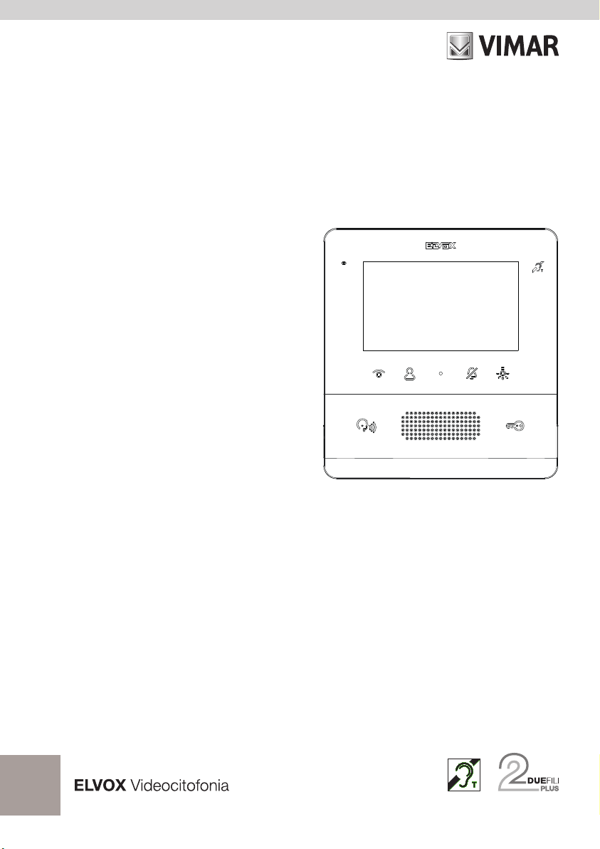
Videocitofono TAB 4,3" Due Fili Plus vivavoce
TAB 4.3 Due Fili Plus hands-free video entryphone
Portier-vidéo TAB 4,3 pouces Due Fili Plus mains libres
Freisprech-Videohaustelefon TAB 4,3" Due Fili Plus
Videoportero TAB 4,3" Due Fili Plus manos libres
Videoporteiro TAB 4,3" Due Fili Plus alta-voz
Θυροτηλεόραση ανοικτής ακρόασης TAB 4,3" Due Fili Plus
Page 2

TAB: 7559
Il manuale istruzioni è scaricabile dal sito www.
vimar.com
Regole di installazione
L’installazione deve essere eettuata da personale qualicato
con l’osservanza delle disposizioni regolanti l’installazione
del materiale elettrico in vigore nel paese dove i prodotti
sono installati.
Conformità normativa
Direttiva EMC
Norme EN 60065, EN 61000-6-1, EN 61000-6-3 e
60118-4.
Regolamento REACh (UE) n. 1907/2006 – art.33. Il
prodotto potrebbe contenere tracce di piombo.
EN
RAEE - Informazione agli utilizzatori
Il simbolo del cassonetto barrato riportato
sull’apparecchiatura o sulla sua confezione indica
che il prodotto alla ne della propria vita utile deve
essere raccolto separatamente dagli altri riuti. L’utente
dovrà, pertanto, conferire l’apparecchiatura giunta a ne
vita agli idonei centri comunali di raccolta dierenziata
dei riuti elettrotecnici ed elettronici. In alternativa alla
gestione autonoma, è possibile consegnare gratuitamente
l’apparecchiatura che si desidera smaltire al distributore, al
momento dell’acquisto di una nuova apparecchiatura di tipo
equivalente. Presso i distributori di prodotti elettronici con
supercie di vendita di almeno 400 m2 è inoltre possibile
consegnare gratuitamente, senza obbligo di acquisto, i
prodotti elettronici da smaltire con dimensioni inferiori a 25
cm. L’adeguata raccolta dierenziata per l’avvio successivo
dell’apparecchiatura dismessa al riciclaggio, al trattamento
e allo smaltimento ambientalmente compatibile contribuisce
ad evitare possibili eetti negativi sull’ambiente e sulla
salute e favorisce il reimpiego e/o riciclo dei materiali di cui
è composta l’apparecchiatura.
Descrizione
Videocitofono della serie Tab, vivavoce da parete per sistema
Due Fili Plus con display a colori LCD 4,3”, altoparlante
per segnalazione chiamate, tastiera capacitiva per funzioni
citofoniche (apertura serratura, autoaccensione, servizi
ausiliari, regolazioni volume, luminosità, contrasto e chiamate
intercomunicanti).
E’ possibile l’installazione in versione da tavolo mediante
l’accessorio base da tavolo 753A, (acquistabile
separatamente).
Utilizzabile da parte dei portatori di protesi acustiche.
Caratteristiche tecniche
• Montaggio: a parete, con staffa metallica, su scatola:
circolare 2M (Vimar V71701), 3M (Vimar V71303,
V71703) verticale e quadrata British standard.
• Display LCD 4,3" 16:9, risoluzione 480x272 pixel
• Livello minimo di segnale video sul bus in ricezione: -20
dBm
• Tastiera capacitiva a sfioramento con simboli
retroilluminati.
• Alimentazione da BUS morsetti 1, 2 - tensione nominale
28Vdc
• Assorbimento:
- in standby: 17 mA
- corrente massima: 280 mA
• Classe ambientale: Classe A1 (uso interno)
• Grado di protezione IP30
• Temperatura di funzionamento: -5 °C - +40 °C (uso
interno)
• Suoneria elettronica con diversificazione delle melodie
(10).
• Ingresso per chiamata fuori porta.
• Dimensioni: 155 x 145 x 23.5 mm
• Dip switch per terminazione impedenza linea.
Funzione di audiofrequenza per protesi
acustiche (Teleloop)
Il videocitofono è utilizzabile da parte dei portatori di protesi
acustiche.
Per un corretto funzionamento dell’apparecchio acustico, fare
riferimento al relativo manuale di istruzioni. La presenza di
oggetti metallici o apparecchi elettronici, può compromettere la
qualità del suono percepito sull’apparecchio acustico.
Manutenzione
Eseguire la pulizia utilizzando un panno morbido. Non versare
acqua sull’apparecchio e non utilizzare alcun tipo di prodotto
chimico.
La pulizia va fatta o ad apparecchio spento (= staccato dal
bus), oppure dopo aver attivato la procedura di pulizia tastiera
(vedere relativo paragrafo nel manuale utente).
Avvertenze per l’utente
Non aprire o manomettere l’apparecchio.
In caso di guasto avvalersi di personale specializzato.
2
IT
Page 3
TAB: 7559
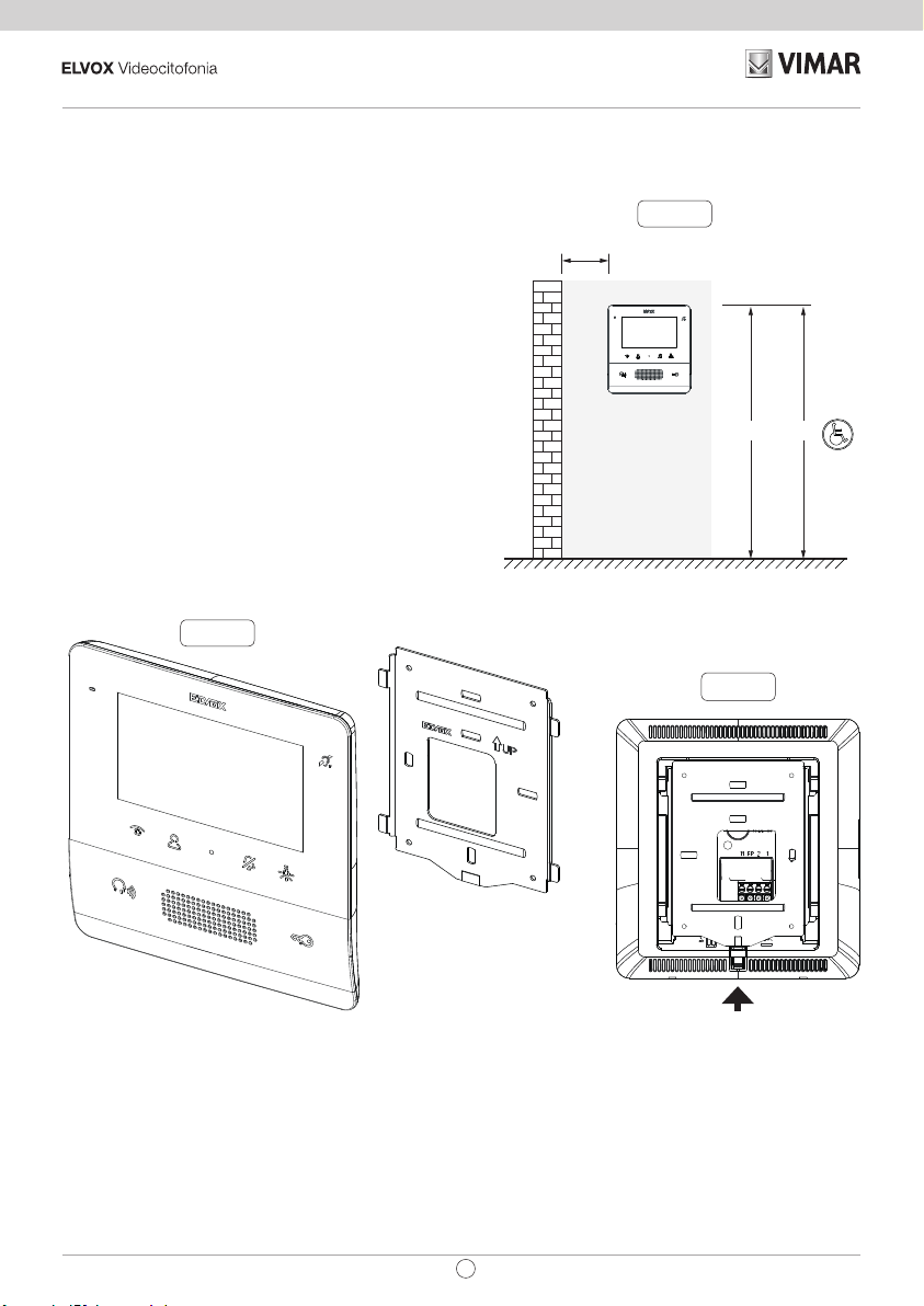
Installazione
Importante: Si consiglia di installare il dispositivo ad un’al-
tezza di circa 160 cm dal pavimento facendo attenzione a
non esporlo a fonti dirette di illuminazione in modo da evitare
fastidiosi fenomeni di riflessione sulla superficie dello schermo
LCD.
Nota: in fig. 1 le misure di installazione consigliate, salvo diver
se indicazioni della normativa vigente in materia.
1. Fissare la piastra a parete, con staffa metallica, su scatola:
circolare 2M (Vimar V71701), 3M (Vimar V71303, V71703)
verticale e quadrata British standard.
2. Cablare la morsettiera (Fig. 4).
3. Provvedere alla terminazione del segnale video (Fig. 4)
4. Alloggiare il videocitofono nel seguente modo: posizionare
il videocitofono sulla piastra tenendolo leggermente solle
vato, a questo punto tenendo premuto il frontale fare una
leggera pressione verso il basso fino all’aggancio.
5. Nel caso in cui fosse necessario togliere il videocitofono
è necessario agire facendo una leggera pressione nell’ap
posita levetta (Fig. 3) e sollevare (dal basso verso l’alto) in
modo da sganciare il videocitofono dal telaio.
Fig. 2
-
-
-
Fig. 1
> 10 cm
1,20m1,60 / 1,65m
Fig. 3
IT
3
Page 4
TAB: 7559
1
K
C
50Ω
B
100Ω
A
ON
12
ON
12
100Ω
M
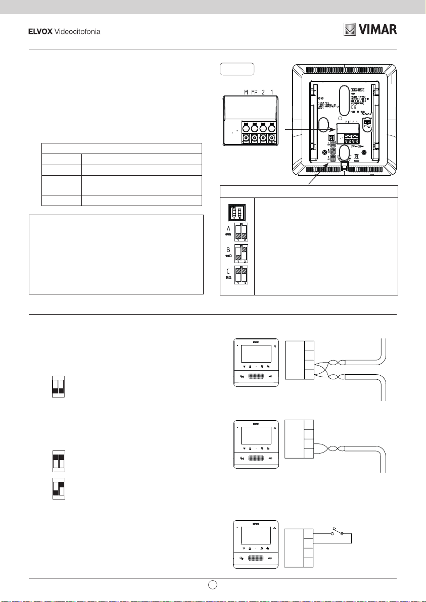
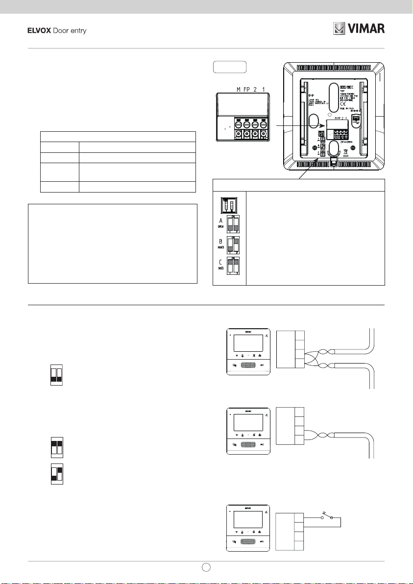
Connessioni
Sul retro è presente una morsettiera per:
• Il collegamento del bus Due Fili Plus
• L’ingresso Fuori Porta locale. La distanza massima del
collegamento è 10 m. Tramite congurazione eseguita
da SaveProg può essere utilizzato come ingresso per la
funzione Allerta. Vedere il relativo paragrafo nel manuale
di installazione e utilizzo.
Morsettiera di collegamento
Morsetti Funzione
1, 2 Linea digitale BUS DUE FILI PLUS.
FP Ingresso tasto chiamata Fuori Porta
locale (riferimento al morsetto M).
M Riferimento massa
Nota: l’Art. 7559 non dispone dei morsetti per l’alimentazione
supplementare. Per questo motivo se la sezione del bus Due Fili
nel quale il posto interno si trova dovesse essere impegnata in
un’altra chiamata / conversazione o un altro 7559 o 40505 dovesse
essere acceso per qualsiasi motivo e in qualsiasi stato, un secondo
7559 o 40505 non si potrà accendere e all’utente verrà dato un
avviso mediante un tono. L’unica azione possibile è il comando di
serratura, luce scale e ausiliario mediante i tasti dedicati, se non
congurati per altri utilizzi, e si può utilizzare la funzione Allerta
come descritto nel manuale di installazione e utilizzo.
Collegamento
Collegamento del posto interno in configurazione
entra/esci
Schema di collegamento entra/esci
ON
Terminazione da applicare
12
OPEN
Fig. 4
Terminazione Video
Selezionare Dip switch per la terminare il
segnale video
A) se il cavo del BUS entra nei morsetti 1, 2 e
prosegue ad un altro posto interno.
B) quando un cavo BUS con impedenza caratte
ristica di 100 Ohm (cavo Elvox 732I o 732H)
entra nei morsetti 1, 2 ed il montante si ferma
nel posto interno
C) quando un cavo BUS con impedenza carat
teristica di 50 Ohm (cavo Cat.5 o Cat.6 con i
doppini accoppiati) entra nei morsetti 1, 2 ed
il montante si ferma nel posto interno.
-
-
M
FP
2
1
Montante
Collegamento del posto interno in congurazione
terminale
Schema di collegamento con cavo che termina nel posto interno
ON
C
12
50Ω
B
Variante per il collegamento del pulsante
fuoriporta o allerta
Collegamento dei morsetto FP/M
4
Terminazione da applicare in funzione
ON
dell’impedenza caratteristica del cavo
12
FP
2
1
Montante
M
FP
2
IT
Page 5
TAB: 7559
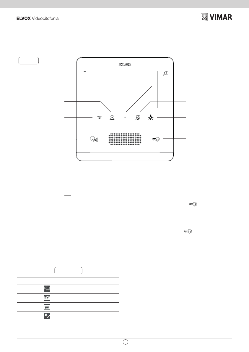
Funzione dei tasti
Fig. 5
T2 (AUX2 / Menu
intercomunicanti)
T1 (Autoaccensione)
P/A (Risposta / Fine
conversazione
/ Chiamata a
centralino)
C (Accesso Menu
congurazione)
T3 (Esclusione suoneria /
Mute microfono)
T4 (Luce scale / Menu
attuazioni)
Serratura
Nel seguito del documento i tasti touch sono denominati
come nella gura (Fig.7):
In stato di riposo, tutti i tasti non eseguono la funzione con il
semplice soramento ma necessitano di una pressione più
lunga (circa 0,4 s): questo per evitare attivazioni o comandi
accidentali. L’avviso del riconoscimento, se non disabilitato
esplicitamente, avviene tramite segnalazione acustica.
I tasti T1..T4 hanno due contesti di funzionamento:
• Azionamenti
• Intercomunicante
Nel contesto Azionamenti, i tasti T1..T4 hanno un default
(quando non sono programmati) che è quello indicato
nella gura seguente (Tabella 1), assieme alle icone di
default:. Possono essere congurati per mezzo del menu
installatore o con SaveProg.
Tabella 1
TASTO ICONA SIGNIFICATO
T1
T2
T3
T4
Auto accensione
Ausiliario 2
F2 ultimo posto esterno
Ausiliario 1
Nel contesto Intercomunicante i tasti T1..T4 non hanno
congurazione di default.
T3 ha la funzionalità di esclusione suoneria / mute mi-
crofono.
Al default, il tasto SERRATURA
tura dell’ultimo posto esterno chiamante o verso il quale
si è eseguita l’autoaccensione.
A riposo lo schermo è completamente spento. Attivando
(con la modalità descritta in precedenza) uno qualsiasi tra
i tasti T1..T4 e SERRATURA
guita la funzione senza accendere il display a meno che
l’esecuzione della funzione stessa non lo richieda, per
esempio l’autoaccensione.
IT
comanda la serra-
al default, viene ese-
5
Page 6

TAB: 7559
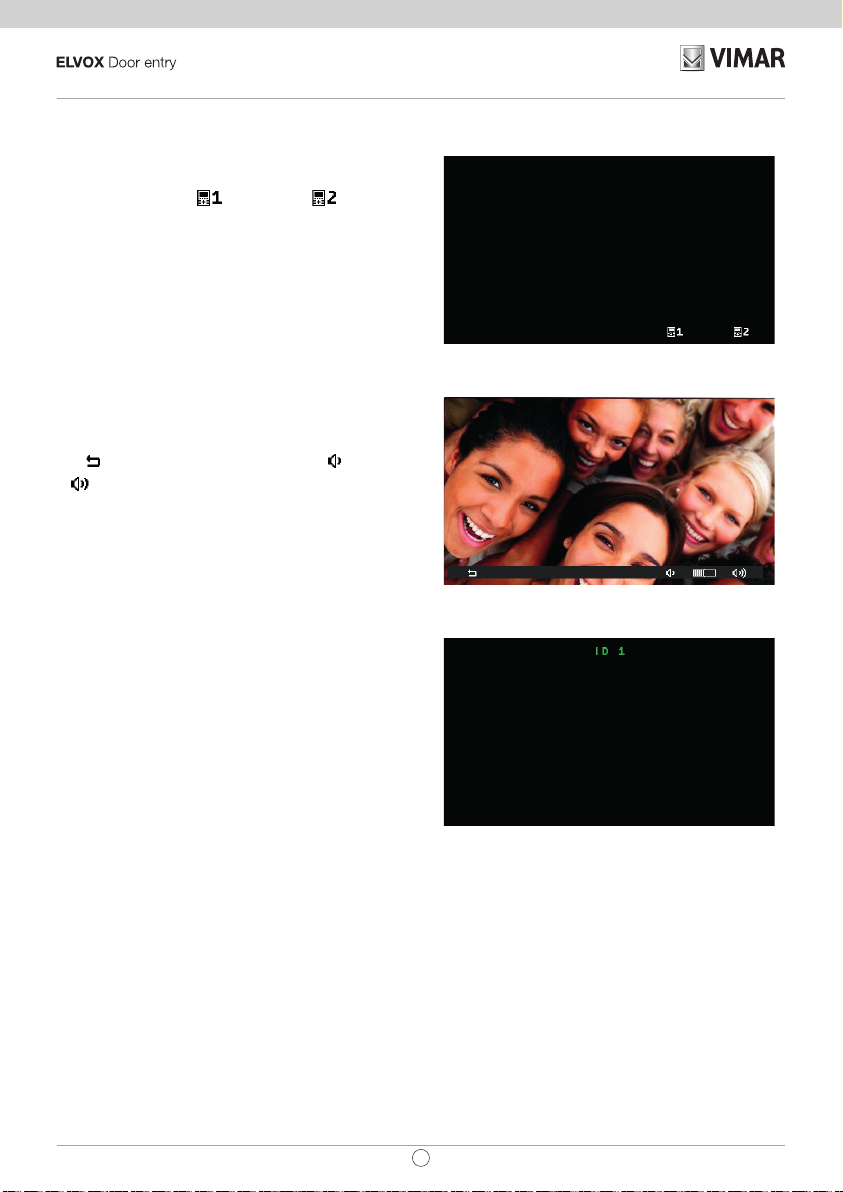
Prima accensione
Il 7559 esce di fabbrica senza ID. Attivando il display
sorando la tastiera l’unica azione possibile è quella
di assegnazione ID come posto interno principale
o secondario :
Prima accensione
Scegliendo uno dei due, il posto interno richiede al
posto esterno Master l’assegnazione dell’ID e i tasti
cambiano di signicato nel modo seguente:
ora serve per annullare la richiesta, T3 e T4
T1
rispettivamente per diminuire e aumentare il livello
della fonica in altoparlante.
Inizializzazione in corso
Al termine dell’assegnazione dell’ID, nella parte alta
del display compare il numero attribuito:
Assegnazione ID
Aggiornamento FW
SaveProg gestisce l’Art. 7559 a partire dalla versione
3.7.0.0.
Driver per PC
I driver sono gli stessi degli altri membri della famiglia TAB.
La prima volta che se ne collega uno a una porta USB, il PC
deve associare alla periferica i driver anche se è già stato
associato un qualsiasi TAB. Il posto interno si identica, a
livello di SaveProg, come ELVOX_P129A.
6
IT
Page 7
TAB: 7559
The instructions manual can be downloaded from
the website www.vimar.com
Installation rules
Installation must be carried out by qualied persons in
compliance with the current regulations regarding the
installation of electrical equipment in the country where the
products are installed.
Regulatory compliance
EMC directive
Standards EN 60065, EN 61000-6-1, EN 61000-6-3 and
EN 60118-4.
REACH (EU) Regulation no. 1907/2006 – Art.33. The
product may contain traces of lead.
WEEE - User information
The crossed bin symbol on the appliance or on its
packaging indicates that the product at the end of its
life must be collected separately from other waste.
The user must therefore hand the equipment at the end of
its life cycle over to the appropriate municipal centres for the
dierentiated collection of electrical and electronic waste.
As an alternative to independent management, you can
deliver the equipment you want to dispose of free of charge
to the distributor when purchasing a new appliance of an
equivalent type. You can also deliver electronic products
to be disposed of that are smaller than 25 cm for free, with
no obligation to purchase, to electronics distributors with a
sales area of at least 400 m2. Proper sorted waste collection
for subsequent recycling, processing and environmentally
conscious disposal of the old equipment helps to prevent
any possible negative impact on the environment and
human health while promoting the practice of reusing and/
or recycling materials used in manufacture.
Technical characteristics
• Wall-mounted, with metal bracket, in box: circular 2M
(Vimar V71701), 3M (Vimar V71303, V71703) vertical
and square British standard.
• LCD 4.3” 16:9 display, resolution 480x272 pixels
• Minimum video signal level on the bus for reception: -20
dBm
• Capacitive touch keypad with backlit symbols.
• Powered from BUS terminals 1, 2 - nominal voltage
28Vdc
• Power consumption:
- in standby: 17 mA
- maximum current: 280 mA
• Ambient class: Class A1 (indoor use)
• IP30 protection rating
• Operating temperature: -5°C to +40°C (indoor use)
• Electronic ringer with 10 different melodies.
• Input for landing call.
• Dimensions: 155 x 145 x 23.5 mm
• DIP switch for line termination impedance.
Audio frequency function for hearing aids
(Teleloop)
The video entryphone can be used by people wearing hearing
aids.
For correct functioning of the hearing aid, please refer to its
instruction manual. Any metal objects or electronic equipment
in the vicinity may aect the quality of the sound received by
the hearing aid.
Maintenance
Clean using a soft cloth. Do not pour water onto the appliance
and do not use any type of chemical product.
Cleaning must be carried out either with the apparatus
powered o (= disconnected from the bus) or after activating
the keypad cleaning procedure (see the relative paragraph in
the user manual).
Description
Wall-mount Tab series hands-free video entryphone for Due
Fili Plus system with 4.3" LCD colour display, loudspeaker for
calls, capacitive keypad for entryphone functions (unlocking,
self-starting, auxiliary services, volume, brightness and
contrast controls) and intercom calls.
Desktop installation is possible with the desktop base
accessory 753A (sold separately).
Can be used by wearers of hearing aids.
EN
Warnings for the user
Do not open or tamper with the appliance.
In the event of faults, contact specialized personnel.
7
Page 8

TAB: 7559
Installation
Important: The device should be installed at a height of
approximately 160 cm off the floor, taking care not to expose it
to direct sources of light so as to avoid annoying glare on the
surface of the LCD screen
Note: Fig. 1 shows the recommended installation distances,
unless otherwise specified by current regulations.
1. Secure the plate to the wall, with metal bracket, in box:
circular 2M (Vimar V71701), 3M (Vimar V71303, V71703)
vertical and square British standard.
2. Wire the terminal block (Fig. 4).
3. Terminate the video signal (Fig. 4)
4. Install the video entryphone as follows: position the video
entryphone on the plate keeping it slightly raised. While
keeping the front panel pressed, apply a light downward
pressure until it clicks into place.
5. Should you need to remove the monitor you need to apply
a light pressure on the lever (Fig. 3) and raise it (from
the bottom upwards) so as to release the monitor from
the chassis.
Fig. 2
Fig. 1
> 10 cm
1,20m1,60 / 1,65m
Fig. 3
8
EN
Page 9
TAB: 7559
1
K
C
50Ω
B
100Ω
A
ON
12
ON
12
100Ω
M
Connections
On the rear there is a terminal board for:
• Connection of the Due Fili Plus bus
• The Landing Call input. The maximum connection distance is
10 m. When suitably programmed using SaveProg, this input
can be used for the Alert function. See relative paragraph
in the installation and operation manual.
Connection terminal block
Terminals Function
1, 2 DUE FILI PLUS digital bus.
FP Landing Call button input (terminal M
reference).
M Reference earth
Note: Art. 7559 does not have terminals for an additional power
supply. For this reason, if the section of the Due Fili bus in which
the internal unit is located is busy with another call/conversation,
or another 7559 or 40505 is switched on for any reason, regardless
of its operating status, it will not be possible to switch on a second
7559 or 40505 and a tone will sound to warn the user. The only
possible action is to operate the lock, stair light or auxiliary function
using the dedicated buttons, provided they are not congured for
other functions; the Alert function can be used as described in the
installation and operation manual.
Connection
Connecting the internal unit in the in/out
configuration
In/out wiring diagram
ON
Termination to apply
12
OPEN
Fig. 4
Video Termination
Select DIP switch to terminate the video
signal
A) if the BUS cable enters terminals 1, 2 and
continues to another internal unit.
B) when a BUS cable with a characteristic
impedance of 100 Ohms (Elvox 732I or 732H
cable) enters terminals 1, 2 and the riser
stops in the internal unit
C) when a BUS cable with characteristic imped
ance of 50 Ohms (Cat. 5 or Cat. 6 twisted pair
cable) enters terminals 1, 2 and the riser stops
in the internal unit.
-
M
FP
2
1
Cable riser
Connecting the internal unit in terminal
conguration
Wiring diagram with cable terminating in the internal unit
ON
C
12
50Ω
B
Variant for connecting the landing or alert button
Connecting the FP/M terminal
Termination to be applied depending
ON
on the characteristic impedance of
the cable
12
FP
2
1
Cable riser
M
FP
2
EN
9
Page 10

TAB: 7559
Key functions
Fig. 5
T2 (AUX2 / Intercom
menu)
T1 (Self-start)
P/A (Answer / End call /
Call to switchboard)
C (Access Menu
conguration)
T3 (Ringtone mute / Mute
microphone)
T4 (Stair light / Actuator
menu)
Lock
In the subsequent sections of this document the touch keys
are designated as shown in the gure (Fig. 5):
At rest, none of the buttons perform the touch function, but must be pressed for longer (around 0.4 s): this
prevents the accidental activation of commands. Unless
specically disabled, the recognition notice is given by
acoustic signalling.
Keys T1..T4 have two operating contexts:
• Operators
• Intercom
In the Drives context, keys T1..T4 have a default (when not
programmed), as indicated in the following gure (Table
1), along with the default icons:. They can be programmed
from the installer menu or using SaveProg.
Table 1
KEY ICON MEANING
T1
T2
T3
T4
Self-start
Aux 2
F2 last outdoor unit
Aux 1
10
In the Intercom context keys T1..T4 have no default
conguration.
T3 has the function of ringtone mute / mute microphone.
By default, the LOCK
outdoor unit to make a call or the outdoor unit for which
self-start procedure was performed.
In standby mode, the screen is completely switched o.
(In the method described above), by activating any one of
the keys T1..T4 and LOCK
performed without switching on the display unless the
function has to do so in order to be performed, such as
self-start.
EN
key controls the lock of the last
by default the function is
Page 11
TAB: 7559
First power up
7559 is supplied without ID. On switching on the
display by touching the keypad, the only action possi-
ble is to assign main or secondary internal
unit as the ID:
First power up
On choosing one of the two, the internal unit requests
ID assignment from the Master outdoor unit and the
functions of the keys change as follows:
now serves to cancel a request, T3 and T4
T1
serve respectively to reduce and increase the
speaker volume.
Initialisation in progress
On completion of the ID assignment procedure, the
number assigned will appear at the top of the display:
Assigning ID
FW updates
SaveProg manages Art. 7559 from version 3.7.0.0 onwards.
Driver for PC
The drivers are the same as for the other device in the TAB
family. The rst time a device is connected to a USB port,
the PC must associate the drivers to the peripheral device
even if a TAB device has already been associated. The
internal unit is identied in SaveProg as ELVOX_P129A.
EN
11
Page 12

TAB: 7559
Le manuel d'instructions peut être téléchargé sur le
site www.vimar.com
Consignes d'installation
L'installation doit être conée à des techniciens qualiés
et exécutée conformément aux dispositions qui régissent
l'installation du matériel électrique en vigueur dans le pays
concerné.
Conformité aux normes
Directive CEM
Normes EN 60065, EN 61000-6-1, EN 61000-6-3 et
60118-4.
Règlement REACH (EU) n° 1907/2006 – art.33. Le produit
pourrait contenir des traces de plomb.
EN
DEEE - Informations destinées aux
utilisateurs
Le pictogramme de la poubelle barrée apposé sur
l'appareil ou sur l'emballage indique que le produit
doit être séparé des autres déchets à la n de son cycle
de vie. L'utilisateur devra coner l'appareil à un centre
municipal de tri sélectif des déchets électroniques et
électrotechniques. Outre la gestion autonome, le détenteur
pourra également coner gratuitement l'appareil qu'il veut
mettre au rebut à un distributeur au moment de l'achat
d'un nouvel appareil aux caractéristiques équivalentes.
Les distributeurs de matériel électronique disposant
d'une surface de vente supérieure à 400 m2 retirent les
produits électroniques arrivés à la n de leur cycle de
vie à titre gratuit, sans obligation d'achat, à condition que
les dimensions de l'appareil ne dépassent pas 25 cm. La
collecte sélective visant à recycler l'appareil, à le retraiter
et à l'éliminer en respectant l'environnement, contribue
à éviter la pollution du milieu et ses eets sur la santé et
favorise la réutilisation des matériaux qui le composent.
Description
Portier-vidéo série Tab, mains libres en saillie pour système
Due Fili Plus avec écran couleurs LCD 4,3 pouces, hautparleur pour signal d'appel, clavier capacitif pour fonctions
interphone (ouverture gâche, auto-allumage, services
auxiliaires, réglage du volume, luminosité, contraste et appels
intercommunicants).
L'installation est possible en version de table grâce à la base
de table 753A (à acheter séparément).
Le portier-vidéo est adapté aux porteurs de prothèses
auditives.
Caractéristiques techniques
• Montage : en saillie, avec étrier métallique, sur boîtier :
rond 2M (Vimar V71701), 3M (Vimar V71303, V71703)
vertical et carré standard britannique.
• Écran LCD 4,3 pouces, 16/9, résolution 480 x 272 pixels
• Niveau minimum du signal vidéo sur le bus en réception
: - 20 dBm
• Clavier capacitif à effleurement avec symboles
rétroéclairés.
• Alimentation par BUS bornes 1, 2 - tension nominale 28
Vcc
• Absorption :
- en mode veille : 17 mA
- au courant maximum : 280 mA
• Classe environnementale : A1 (usage intérieur)
• Indice de protection IP30
• Température de fonctionnement : - 5 °C - + 40 °C (usage
intérieur)
• Sonnerie électronique avec diversification des mélodies
(10).
• Entrée pour appel de palier.
• Dimensions : 155 x 145 x 23,5 mm
• Commutateur pour terminaison impédance ligne.
Fonction audiofréquence pour prothèses
auditives (Téléboucle)
Le portier-vidéo est adapté aux porteurs de prothèses
auditives.
Pour assurer le fonctionnement de l'appareil acoustique, se
reporter au mode d'emploi de ce dernier. La présence d'objets
métalliques ou d'appareils électroniques peut compromettre la
qualité de la réception sur l’appareil acoustique.
Maintenance
Nettoyer avec un chion doux. Ne pas verser d'eau sur
l'appareil et n'utiliser aucun produit chimique.
Le nettoyage doit être exécuté quand l'appareil est éteint
(= débranché du bus) ou après avoir activé la procédure de
nettoyage du clavier (voir paragraphe dédié dans le manuel
utilisateur).
Recommandations pour l’utilisateur
Ne pas ouvrir ni modier l’appareil.
En cas de panne, s'adresser à un technicien spécialisé.
12
FR
Page 13

TAB: 7559
Installation
Important : Il est conseillé d'installer le dispositif à 160 cm
du sol en ayant soin de ne pas l'exposer directement à une
source d'éclairage afin d'éviter tout reflet sur l'écran LCD.
Remarque : la fig. 1 indique les cotes conseillées pour l'ins
tallation, sauf autre disposition de la législation en vigueur.
1. Fixer la plaque en saillie, avec étrier métallique, sur boîtier
: rond 2M (Vimar V71701), 3M (Vimar V71303, V71703)
vertical et carré standard britannique.
2. Câbler le bornier (Fig. 4).
3. Réaliser la terminaison du signal vidéo (Fig. 4).
4. Positionner le portier-vidéo de la manière suivante : placer
le portier-vidéo sur la plaque en le soulevant légèrement.
En appuyant sur la façade, exercer une légère pression
vers le bas jusqu'à l'enclenchement.
5. Pour enlever la plaque-vidéo, exercer une légère pression
sur le levier spécial (Fig. 3) et le soulever de bas en haut
pour décrocher le portier-vidéo du châssis.
Fig. 2
-
Fig. 1
> 10 cm
1,20m1,60 / 1,65m
Fig. 3
FR
13
Page 14

TAB: 7559
1
K
C
50Ω
B
100Ω
A
ON
12
ON
12
100Ω
M
Branchements
Un bornier est installé à l'arrière de l'appareil pour :
• Le branchement du bus Due Fili Plus
• L'entrée palier locale. La distance maximale de connexion
est de 10 m. Après avoir procédé à sa conguration via
SaveProg, il est possible de l'utiliser comme entrée pour
la fonction Alerte. Consulter le paragraphe correspondant
dans le manuel d'installation et d'utilisation.
Bornier de connexion
Bornes Fonction
1, 2 Ligne numérique BUS DUE FILI PLUS.
FP Entrée touche appel palier locale (reliée
à la borne M).
M Référence masse
Remarque : l’art. 7559 ne dispose pas de borne pour une alimentation supplémentaire. Par conséquent, si la section du bus
Due Fili dans laquelle se trouve le poste intérieur est occupée
par un autre appel/conversation ou qu'un autre dispositif 7559
ou 40505 est allumé pour une raison quelconque et dans un état
quelconque, un deuxième dispositif 7559 ou 40505 ne pourra
pas s'allumer et l'utilisateur recevra un avertissement sonore. La
seule action possible est la commande de la gâche, de l'éclairage
escalier et auxiliaire à travers les touches dédiées si elles ne sont
pas congurées pour d'autres utilisations, avec possibilité d'utili
ser la fonction Alerte en suivant les explications dans le manuel
d'installation et d'utilisation.
-
Connexion
Raccordement du poste intérieur en configuration
entrée/sortie
Schéma de connexion entrer/sortir
ON
Terminaison à appliquer
12
OPEN
Fig. 4
Terminaison vidéo
Sélectionner le commutateur pour la
terminaison du signal vidéo
A) si le câble du BUS arrive aux bornes 1, 2 et
continue vers un autre poste intérieur
B) quand un câble BUS avec une impédance
caractéristique de 100 ohms (câble Elvox
732I ou 732H) arrive aux bornes 1, 2 et que la
colonne montante s'arrête au poste intérieur
C) quand un câble BUS ayant une impédance
caractéristique de 50 ohms (câble cat. 5 ou
cat. 6 à paires torsadées) arrive aux bornes
1, 2 et que la colonne montante s'arrête au
poste intérieur.
M
FP
2
1
Colonne montante
Raccordement du poste intérieur en conguration
terminal
Schéma de raccordement avec câble se terminant dans le poste intérieur
ON
C
12
50Ω
B
Variante pour le raccordement du bouton palier
ou alerte
Connexion des bornes FP/M
14
Terminaison à appliquer en fonction de
ON
l’impédance caractéristique du câble
12
FP
2
1
Colonne
montante
M
FP
2
FR
Page 15

TAB: 7559
Fonction des touches
Fig. 5
T2 (AUX2 / Menu appels
intercommunicants)
T1 (Auto-allumage)
P/A (Réponse / Fin de
conversation / Appel
au standard)
C (Accès Menu
Conguration)
T3 (Exclusion sonnerie /
Micro Mute)
T4 (Éclairage escalier /
Menu activations)
Gâche
Dans les pages qui suivent, les touches tactiles portent le
même nom que sur la gure (Fig.7) :
Au repos, aucune touche n'exécute la fonction par eeure-
ment. Il faudra garder le doigt dessus (env. 0,4 secondes)
pour éviter toute commande ou actionnement accidentel.
La reconnaissance est signalée par un signal sonore, à
moins qu'elle n'ait été volontairement acquittée.
Les touches T1..T4 ont deux contextes de fonctionnement :
• actionnements
• intercommunication
Dans le contexte Actionnements, les touches T1..T4 ont
une valeur par défaut (si elles n'ont pas été programmées),
indiquée sur la gure ci-après (Tableau 1), avec les icônes
par défaut. Elles peuvent être congurées à travers le
menu installateur ou SaveProg.
Tableau 1
TOUCHE ICÔNE SIGNIFICATION
T1
T2
T3
T4
Auto-allumage
AUX 2
F2 dernier poste extérieur
AUX 1
Dans le contexte Intercommunicant, les touches T1..T4 ne
disposent pas d'une conguration par défaut.
T3 a une fonction exclusion sonnerie / micro mute.
Par défaut, la touche GÂCHE
du dernier poste extérieur appelant ou vers lequel l'auto-allumage a été exécuté.
Au repos, l'écran reste éteint. En commandant (dans la
modalité préalablement décrite) l'une des touches T1..T4
et GÂCHE
exécuté sans allumer l'écran, à moins que l’exécution de
la fonction ne le nécessite, par exemple pour l’auto-allumage.
FR
sur la valeur par défaut, la fonction est
commande la gâche
15
Page 16

TAB: 7559
Premier allumage
Le dispositif 7559 quitte l'usine sans ID. Quand on
active l'écran en eeurant le clavier, la seule action
possible est l'attribution d'un ID comme poste intérieur principal ou secondaire :
Premier allumage
Après la sélection d'une de ces deux options, le poste
intérieur demande au poste extérieur maître l'attribution
d'un ID, les touches changent de signication de la
façon suivante :
permet désormais d'annuler la demande, T3
T1
et T4 permettent respectivement de diminuer
et d'augmenter le niveau de phonie du haut-parleur.
Initialisation en cours
Après l'attribution de l'ID, le numéro correspondant
s'ache en haut de l'écran :
Attribution ID
Mise à jour du microprogramme
SaveProg gère l'art. 7559 à partir de la version 3.7.0.0.
Driver pour PC
Les drivers sont les mêmes que pour les autres dispositifs
TAB. La première fois qu'on connecte un de ces dispositifs
au port USB, le PC doit associer les drivers au périphérique
même s'il a déjà été associé à un TAB. Le poste intérieur
s'ache dans SaveProg, comme ELVOX_P129A.
16
FR
Page 17

TAB: 7559
Die Anleitung kann von der Website www.vimar.
Technische Merkmale
com heruntergeladen werden
Installationsvorschriften
Die Installation muss durch Fachpersonal gemäß den im
Anwendungsland des Geräts geltenden Vorschriften zur
Installation elektrischen Materials erfolgen.
Normkonformität
EMV-Richtlinie
Normen EN 60065, EN 61000-6-1, EN 61000-6-3 und
60118-4
.
REACH-Verordnung (EG) Nr. 1907/2006 – Art.33. Das
Erzeugnis kann Spuren von Blei enthalten.
EN
WEEE-Richtlinie über Elektro- und
Elektronik-Altgeräte Benutzerinformation
Das Symbol der durchgestrichenen Mülltonne auf
dem Gerät oder der Verpackung weist darauf hin, dass das
Produkt am Ende seiner Lebensdauer getrennt von anderen
Abfällen zu sammeln ist. Der Benutzer muss das Altgerät bei
den im Sinne dieser Richtlinie eingerichteten kommunalen
Sammelstellen abgeben. Alternativ hierzu kann das zu
entsorgende Gerät beim Kauf eines neuen gleichwertigen
Geräts dem Fachhändler kostenlos zurückgegeben
werden. Darüber hinaus besteht die Möglichkeit, die zu
entsorgenden Elektronik-Altgeräte mit einer Größe unter 25
cm bei Elektronikfachmärkten mit einer Verkaufsäche von
mindestens 400 m2 kostenlos ohne Kaufpicht eines neuen
Geräts abzugeben. Die korrekte getrennte Sammlung des
Geräts für seine anschließende Zuführung zum Recycling,
zur Behandlung und zur umweltgerechten Entsorgung
trägt dazu bei, mögliche nachteilige Auswirkungen auf die
Umwelt und auf die Gesundheit zu vermeiden und fördert
die Wiederverwertung der Werkstoe des Geräts.
Tonfrequenz-Funktion für Hörgeräte
(Teleschlinge)
Das Videohaustelefon eignet sich für Hörgeräteträger.
Für den korrekten Betrieb des Hörgeräts wird auf die
entsprechende Bedienungsanleitung verwiesen. Eventuell
vorhandene Gegenstände aus Metall oder elektronische
Geräte können die am Hörgerät empfangene Tonqualität
beeinträchtigen.
Wartung
Für die Wartung ein weiches Tuch verwenden. Kein Wasser
auf das Gerät verschütten und chemische Reinigungsmittel
vermeiden.
Die Reinigung hat bei ausgeschaltetem (= vom Bus
getrenntem) Gerät bzw. nach Aktivierung des Vorgangs
Tastaturreinigung (siehe entsprechenden Abschnitt in der
Bedienungsanleitung) zu erfolgen.
Beschreibung
Aufputz-Freisprech-Videohaustelefon der Serie Tab für
Due Fili Plus mit 4,3"-LCD-Farbdisplay, Lautsprecher für
Rufmeldung, kapazitiver Tastatur für Haustelefon-Funktionen
(Türöffner, Selbsteinschaltung, Zusatzfunktionen, Einstellung
von Lautstärke, Helligkeit und Kontrast) und Internrufe.
Installation als Tischgerät mithilfe des Tischzubehörs 753A
(separat erhältlich).
Das Videohaustelefon eignet sich für Hörgeräteträger.
Hinweise für den Benutzer
Das Gerät auf keinen Fall önen oder manipulieren.
Bei Störungen Fachpersonal hinzuziehen.
• Aufputzmontage mit Metallbügel, auf Gehäuse: rund 2M
(Vimar V71701), 3M (Vimar V71303, V71703) vertikal
und quadratisch British Standard.
• 4,3"-LCD-Display 16:9, Auflösung 480x272 Pixel
• Min. Videosignalpegel auf Bus bei Empfang: -20 dBm
• Kapazitive Touch-Tastatur mit hinterbeleuchteten
Symbolen.
• Spannungsversorgung vom BUS Klemmen 1, 2 Nennspannung 28Vdc
• Stromaufnahme:
- Standby: 17 mA
- max. Stromaufnahme: 280 mA
• Umweltklasse: Klasse A1 (Innenbereiche)
• Schutzart IP30
• Betriebstemperatur: -5 °C / +40 °C (Innenbereich)
• Elektronisches Läutwerk mit Diversifizierung der
Melodien (10).
• Eingang für Etagenruf.
• Abmessungen: 155 x 145 x 23.5 mm
• DIP-Schalter für Terminierung Leitungsimpedanz.
DE
17
Page 18

TAB: 7559
Installation
Wichtig: Das Gerät sollte in einer Höhe von ca. 160 cm zum
Boden installiert und keiner direkten Beleuchtung ausgesetzt
werden, um störende Spiegelungen auf dem LCD-Bildschirm
zu vermeiden.
Hinweis: Abb. 1 enthält die empfohlenen Einbaumaße, vor
behaltlich anderslautender Angaben nach einschlägigen
Rechtsvorschriften.
1. Die Aufputzplatte mit Metallbügel auf Gehäuse montieren:
rund 2M (Vimar V71701), 3M (Vimar V71303, V71703)
vertikal und quadratisch British Standard.
2. Die Klemmenleiste verkabeln (Abb. 4).
3. Die Terminierung des Videosignals vornehmen (Abb. 4)
4. Das Videohaustelefon folgendermaßen einsetzen: Das
Videohaustelefon in die Platte einsetzen und dabei etwas
anheben. Die Vorderseite festhalten und bis zum hörbaren
Einrasten leicht nach unten drücken.
5. Zur Abnahme des Videohaustelefons den Hebel leicht ein
drücken (Abb. 3) und (von unten nach oben) anheben, bis
sich das Videohaustelefon aus dem Rahmen löst.
Abb. 2
-
-
Abb. 1
> 10 cm
1,20m1,60 / 1,65m
Abb. 3
18
DE
Page 19

TAB: 7559
1
K
C
50Ω
B
100Ω
A
ON
12
ON
12
100Ω
M
Anschlüsse
Die Klemmenleiste auf der Rückseite dient:
• Zum Anschluss des Due Fili Plus Busses
• Für den lokalen Etageneingang. Die maximale An
schlusslänge beträgt 10 m. Kann mittels Konguration
über SaveProg als Eingang für die Funktion Warnmeldung
verwendet werden. Siehe entsprechenden Abschnitt in der
Installations- und Bedienungsanleitung.
-
Anschlussklemmenleiste
Klemmen Funktion
1, 2 Digitale DUE FILI PLUS BUS-Leitung.
FP Eingang lokale Etagenruftaste (Signal
an Klemme M).
M Massesignal
Hinweis: Der Art. 7559 verfügt nicht über Klemmen für die Zusatzversorgung. Sollte der Bus-Abschnitt der Innenstelle durch einen
anderen Ruf / ein anderes Gespräch belegt oder ein weiterer
Art. 7559 oder 40505 aus welchem Grund auch immer in einem
beliebigen Zustand eingeschaltet sein, so kann ein zweiter Art.
7559 oder 40505 nicht eingeschaltet werden, was dem Benutzer
mit einem Tonzeichen gemeldet wird. Die einzig mögliche Aktion
ist die Schaltung des Türöners, der Treppenhausbeleuchtung
und Hilfsfunktion über die dedizierten Tasten, sofern diese nicht
für andere Befehle konguriert wurden, sowie die Verwendung der
Funktion Warnmeldung, wie in der Installations- und Bedienungs
anleitung beschrieben.
-
Anschluss
Anschluss der Innenstelle in Konfiguration ein/aus
Anschlussplan ein/aus
ON
Anzubringende Terminierung
12
OPEN
Abb. 4
Videoterminierung
DIP-Schalter für die Terminierung des
Videosignals wählen
A) Wenn das BUS-Kabel in die Klemmen 1, 2
eintritt und zu einer anderen Innenstelle wei
terführt.
B) Wenn ein BUS-Kabel mit typischer Impedanz
100 Ohm (Elvox Kabel 732I oder 732H) in die
Klemmen 1, 2 eintritt und die Steigleitung an
der Innenstelle endet
C) Wenn ein BUS-Kabel mit typischer Impedanz
50 Ohm (Kabel Cat.5 oder Cat.6 mit gepaar
ten Doppeladern) in die Klemmen 1, 2 eintritt
und die Steigleitung an der Innenstelle endet.
-
-
M
FP
2
1
Steigleitung
Anschluss der Innenstelle in Konguration als
Endgerät
Anschlussplan mit in der Innenstelle endendem Kabel
ON
C
12
50Ω
B
Variante für den Anschluss der Etagenruftaste
oder Warnmeldung
Anschluss der Klemme FP/M
Anzubringende Terminierung je nach
ON
typischer Impedanz des Kabels
12
FP
2
1
Steigleitung
M
FP
2
DE
19
Page 20

TAB: 7559
Tastenfunktionen
Abb. 5
T2 (AUX2 / Menü
Internrufe)
T1 (Selbsteinschaltung)
P/A (Antwort /
Gesprächsende / Ruf
an Pförtnerzentrale)
C (Aufrufen des
Kongurationsmenüs)
T3 (Ruftonabschaltung /
Stummschaltung des
Mikrofons)
T4 (Treppenhausbe
leuchtung / Menü
Betätigungen)
Türöner
-
Im weiteren Dokumenttext sind die Touch-Tasten gemäß
Abbildung (Abb. 5) bezeichnet:
Im Ruhezustand führen alle Tasten die Funktion nicht
durch einfachen Touch aus, sondern durch längeres Drücken (ca. 0,4 s): damit werden unbeabsichtigte Aktivierungen oder Steuerbefehle vermieden. Die Erkennung, sofern
nicht ausdrücklich deaktiviert, wird durch ein akustisches
Signal gemeldet.
Die Tasten T1..T4 weisen zwei Funktionsumgebungen auf:
• Betätigungen
• Internruf
In der Umgebung Betätigungen verfügen die Tasten T1..
T4 (soweit nicht programmiert) über die in folgender Abbildung angegebene Werkseinstellung (Tabelle 1), wie auch
über die werkseitigen Symbole. Die Einstellung kann mit
dem Menü Installateur oder mittels SaveProg erfolgen.
Tabelle 1
TASTE SYMBOL BEDEUTUNG
T1
T2
T3
T4
Selbsteinschaltung
AUX 2
F2 der letzten Außenstelle
AUX 1
20
In der Umgebung Internruf sind die Tasten T1..T4 nicht
werkseitig konguriert.
T3 hat die Funktion Ruftonabschaltung / Stummschaltung
des Mikrofons.
Auf Werkseinstellung steuert die Taste TÜRÖFFNER
das Türschloss der zuletzt rufenden oder selbsteingeschalteten Außenstelle.
Das Display ist im Ruhezustand erloschen. Durch Aktivieren (in der vorab beschriebene Weise) einer der Tasten
T1..T4 und TÜRÖFFNER
die Funktion ohne Einschalten des Displays ausgeführt,
soweit dies die Ausführung der Funktion nicht erfordert,
zum Beispiel im Fall der Selbsteinschaltung.
DE
auf Werkseinstellung, wird
Page 21

TAB: 7559
Erstmalige Einschaltung
7559 wird ohne ID angeliefert. Bei Aktivieren des
Displays durch einen Touch auf die Tastatur besteht
die einzig mögliche Aktion in der ID-Zuweisung als
Haupt- oder Neben-Innenstelle :
Erstmalige Einschaltung
Nach Auswahl einer der beiden Optionen fordert die Innenstelle die Master-Außenstelle zur ID-Zuweisung auf,
wobei sich die Bedeutung der Tasten wie folgt ändert:
dient nun zum Abbrechen der Auorderung, T3
T1
und T4 jeweils um die Gesprächslautstärke
des Lautsprechers zu verringern oder zu erhöhen.
Ablaufende Initialisierung
Nach der ID-Zuweisung erscheint die zugewiesene
Nummer oben am Display:
ID-Zuweisung
FW-Aktualisierung
SaveProg unterstützt den Art. 7559 ab Version 3.7.0.0.
PC-Treiber
Die Treiber sind mit denen der anderen Modelle aus der
TAB-Familie identisch. Beim ersten Anschluss an einen
USB-Port muss der PC die Treiber dem Peripheriegerät
auch dann zuweisen, wenn bereits ein beliebiges TAB
zugewiesen wurde. Die Innenstelle wird unter SaveProg
als ELVOX_P129A identiziert.
DE
21
Page 22

TAB: 7559
El manual de instrucciones se puede descargar
desde la página www.vimar.com
Normas de instalación
La instalación debe ser realizada por personal cualicado
cumpliendo con las disposiciones en vigor que regulan el
montaje del material eléctrico en el país donde se instalen
los productos.
Conformidad a las normas
Directiva sobre compatibilidad electromagnética
Normas EN 60065, EN 61000-6-1, EN 61000-6-3 y
60118-4.
Reglamento REACH (UE) n. 1907/2006 – art.33. El
producto puede contener trazas de plomo.
EN
RAEE - Información a los usuarios
El símbolo del contenedor tachado que aparece
en el equipo o su envase indica que al nal de su
vida útil el mismo no debe desecharse junto con
otros residuos. Al nal de su vida útil, el usuario deberá
entregar el equipo a un centro de recogida de residuos
electrotécnicos y electrónicos. También puede entregar
gratuitamente el equipo usado al establecimiento donde
compre un nuevo equipo de tipo equivalente. En los
establecimientos de distribución de equipos electrónicos
con una supercie de venta de al menos 400 m
posible entregar gratuitamente, sin obligación de compra,
productos electrónicos usados de tamaño inferior a 25 cm.
La recogida selectiva de estos residuos facilita el reciclaje
del aparato y sus componentes, permite su tratamiento y
eliminación de forma compatible con el medio ambiente y
evita posibles efectos perjudiciales para la naturaleza y la
salud de las personas.
2
es
Características técnicas
• Montaje: de superficie, con soporte metálico, sobre
caja: circular 2M (Vimar V71701), 3M (Vimar V71303,
V71703) vertical y cuadrada con estándar británico.
• Pantalla LCD 4,3" 16:9, resolución 480x272 píxeles
• Nivel mínimo de señal vídeo en el bus durante la
recepción: -20 dBm
• Teclado capacitivo táctil con símbolos retroiluminados.
• Alimentación por BUS bornes 1, 2 - tensión nominal 28
Vcc
• Absorción:
- en standby: 17 mA
- corriente máxima: 280 mA
• Clase medioambiental: Clase A1 (uso interno)
• Grado de protección IP30
• Temperatura de funcionamiento: -5 °C - +40 °C (uso
interno)
• Timbre electrónico con distintos tonos (10).
• Entrada para llamada fuera de la puerta.
• Medidas: 155 x 145 x 23.5 mm
• Conmutador DIP para terminación impedancia línea.
Función de audiofrecuencia para audífonos
(transmisor inductivo)
El videoportero puede ser utilizado por personas con audífono.
Para el correcto funcionamiento del audífono, consulte el
correspondiente manual de instrucciones. La presencia de
objetos metálicos o aparatos electrónicos puede perjudicar la
calidad del sonido percibido con el audífono.
Mantenimiento
Limpie con un paño suave. No moje el aparato con agua y no
utilice ningún tipo de producto químico.
La limpieza debe realizarse con el aparato apagado (=
desconectado del bus) o después de activar el procedimiento
de limpieza del teclado (consulte el apartado correspondiente
en el manual de usuario).
Descripción
Videoportero manos libres de la serie Tab, de superficie
para sistema Due Fili Plus con pantalla en color LCD 4,3",
altavoz para señalización de llamadas, teclado capacitivo
para funciones de portero automático (apertura de cerradura,
autoencendido, servicios auxiliares, ajuste de volumen, brillo
y contraste y llamadas intercomunicantes).
El montaje en versión de sobremesa es posible gracias
al correspondiente accesorio 753A (puede comprarse por
separado).
El videoportero puede ser utilizado por personas con audífono.
22
ES
Advertencias para el usuario
No abra, ni manipule el aparato.
En caso de avería, acuda a personal especializado.
Page 23

TAB: 7559
Montaje
Importante: Se recomienda instalar el dispositivo a una
altura de unos 160 cm del suelo teniendo cuidado de no exponerlo a fuentes directas de iluminación para evitar molestos
fenómenos de reflexión en la superficie de la pantalla LCD.
Nota: en la fig. 1 se muestran las medidas de montaje
recomendadas, salvo que la normativa vigente en materia
establezca otras.
1. Fije la placa a la pared, con soporte metálico, sobre la
caja: circular 2M (Vimar V71701), 3M (Vimar V71303,
V71703) vertical y cuadrada con estándar británico.
2. Cablee la caja de bornes (Fig. 4).
3. Configure la terminación de la señal de vídeo (Fig. 4).
4. Montaje del videoportero: colóquelo sobre la placa mante
niéndolo ligeramente levantado y entonces, manteniendo
presionado el frente, empuje suavemente hacia abajo
hasta que quede encajado.
5. Si fuera necesario soltar el videoportero, hay que ejercer
una ligera presión en la pestaña correspondiente (fig. 3)
y levantar (de abajo hacia arriba) para desenganchar el
videoportero del bastidor.
Fig. 2
-
Fig. 1
> 10 cm
1,20m1,60 / 1,65m
Fig. 3
ES
23
Page 24

TAB: 7559
1
K
C
50Ω
B
100Ω
A
ON
12
ON
12
100Ω
M
Conexiones
En la parte posterior hay una regleta de conexión para:
• La conexión del bus Due Fili Plus
• La entrada fuera de la puerta local La distancia máxima de
la conexión es de 10 m. Mediante la conguración realizada
por SaveProg se puede utilizar como entrada para la función
Alerta. Consulte el apartado correspondiente del manual de
instalación y utilización.
Regleta de conexión
Bornes Función
1, 2 Línea digital BUS DUE FILI PLUS.
FP Entrada tecla llamada fuera de la puerta
local (referencia al borne M).
M Referencia masa
Nota: el art. 7559 no cuenta con bornes para alimentación adicional. Por esta razón si la sección del Bus Due Fili en el que se encuentra el aparato interno estuviera comunicando por otra llamada
/ conversación o bien si otro 7559 o 40505 estuviera encendido
por cualquier motivo y en cualquier estado, no se podría encender
un segundo 7559 o 40505 y se avisaría al usuario con un tono. La
única acción posible es el accionamiento de cerradura, luz de escalera y auxiliar mediante las teclas correspondientes, si no están
conguradas para otras funciones, y se puede utilizar la función
Alerta como se indica en el manual de instalación y utilización.
Conexión
Conexión del aparato interno en configuración
entrar/salir
Esquema de conexión entrar/salir
ON
Terminación a aplicar
12
OPEN
Fig. 4
Terminación vídeo
Seleccione el conmutador DIP para la terminación de la señal de vídeo:
A) si el cable del BUS entra en los bornes 1, 2 y
continúa hasta otro aparato interno.
B) cuando un cable BUS con impedancia carac
terística de 100 ohmios (cable Elvox 732I o
732H) entra en los bornes 1, 2 y el montante
termina en el aparato interno
C) cuando un cable BUS con impedancia carac
terística de 50 ohmios (cable Cat.5 o Cat.6
con los cables de pares acoplados) entra en
los bornes 1, 2 y el montante termina en el
aparato interno.
-
-
M
FP
2
1
Montante
Conexión del aparato interno en conguración
terminal
Esquema de conexión con cable que termina en el aparato interno
ON
C
12
50Ω
B
Variante para la conexión del pulsador fuera de la
puerta o alerta
Conexión de los bornes FP/M
24
Terminación a aplicar según la
ON
impedancia característica del cable
12
FP
2
1
Montante
M
FP
2
ES
Page 25

TAB: 7559
Función de las teclas
Fig. 5
T2 (AUX2 / Menú
intercomunicantes)
T1 (Autoencendido)
P/A (Respuesta / Fin
conversación /
Llamada a centralita)
C (Acceso Menú
conguración)
T3 (Exclusión del timbre /
Mute micrófono)
T4 (Luz escalera / Menú
actuadores)
Cerradura
En el resto del documento las teclas táctiles se denominan
como se indica en la gura (Fig. 5):
Estando en reposo, todas las teclas no ejecutan la función simplemente rozándolos, sino que requieren una
presión más prolongada (unos 0,4 segundos): esto sirve
para evitar activaciones o mandos accidentales. Si no se
desactiva expresamente, el reconocimiento, se notica
mediante una señal acústica.
Las teclas T1..T4 tienen dos ámbitos de funcionamiento:
• Accionamientos
• Intercomunicante
En el ámbito Accionamientos, las teclas T1..T4 tienen una
conguración predeterminada (si no están programadas)
que es el indicado en la gura siguiente (Tabla 1), junto
con los iconos predeterminados. Se pueden congurar por
medio del menú Instalador o con SaveProg.
Tabla 1
TECLA ICONO SIGNIFICADO
T1
T2
T3
T4
Autoencendido
Auxiliar 2
F2 último aparato externo
Auxiliar 1
En el ámbito Intercomunicante las teclas T1..T4 no tienen
una conguración predeterminada.
T3 desempeña la función de exclusión del timbre / mute
micrófono.
Por defecto, la tecla CERRADURA
dura del último aparato externo que ha llamado o hacia
el cual se ha realizado el autoencendido.
En reposo la pantalla está totalmente apagada. Al activar
(en el modelo descrito anteriormente) cualquiera de las
teclas T1..T4 y CERRADURA
la función se ejecuta sin encender la pantalla siempre que
la ejecución de la función lo requiera, por ejemplo el autoencendido.
ES
acciona la cerra-
como predeterminado,
25
Page 26

TAB: 7559
Primer encendido
El 7559 sale de fábrica sin ID. Al activar la pantalla
rozando el teclado, la única acción posible es la
asignación del ID como aparato interno principal
o secundario :
Primer encendido
Al seleccionar uno de los dos, el aparato interno solicita
al aparato externo Master la asignación del ID y las
teclas cambian de signicado de la forma siguiente:
ahora sirve para anular la solicitud, T3 y
T1
T4 respectivamente para disminuir y aumentar el
nivel de la línea fónica en el altavoz.
Inicializando...
Al nal de la asignación del ID, en la parte alta de la
pantalla aparece el número asignado:
Asignación ID
Actualización FW
SaveProg gestiona el art. 7559 a partir de la versión
3.7.0.0.
Controladores para PC
Los controladores son los mismos de los demás miembros
de la familia TAB. La primera vez que se conecta uno a
un puerto USB, el PC debe asociar al periférico los controladores aunque ya haya sido asociado cualquier TAB.
A nivel de SaveProg, el aparato interno se identica como
ELVOX_P129A.
26
ES
Page 27

TAB: 7559
É possível descarregar o manual de instruções a
partir do site www.vimar.com
Regras de instalação
A instalação deve ser efetuada por pessoal qualicado de
acordo com as disposições que regulam a instalação de
material elétrico, vigentes no país em que os produtos são
instalados.
Conformidade normativa
Diretiva EMC
Normas EN 60065, EN 61000-6-1, EN 61000-6-3 e
60118-4.
Regulamento REACh (UE) n.º 1907/2006 – art.33. O
produto poderá conter vestígios de chumbo.
EN
REEE - Informação aos utilizadores
O símbolo do contentor barrado existente no
equipamento ou na sua embalagem indica que,
no m da respetiva vida útil, o produto deve ser
recolhido separadamente dos outros resíduos. O utilizador
deverá, portanto, depositar o equipamento em m de vida
nos respetivos centros municipais de recolha seletiva de
resíduos eletrotécnicos e eletrónicos. Em alternativa à
gestão autónoma, é possível entregar gratuitamente ao
distribuidor o aparelho que se pretende eliminar, aquando
da compra de um novo equipamento de tipo equivalente.
Nos distribuidores de produtos eletrónicos com uma
superfície de venda de pelo menos 400 m2 é ainda possível
entregar gratuitamente, sem obrigação de compra, os
produtos eletrónicos a eliminar com dimensões inferiores
a 25 cm. A recolha seletiva adequada para o posterior
reencaminhamento do aparelho em m de vida para a
reciclagem, tratamento e eliminação ambientalmente
compatível contribui para evitar possíveis efeitos
negativos sobre o ambiente e sobre a saúde e favorece a
reutilização e/ou reciclagem dos materiais que compõem
o equipamento.
Descrição
Videoporteiro da série Tab, alta-voz, de parede para sistema
Due Fili Plus com display a cores LCD 4,3”, altifalante
para sinalização de chamadas, teclado capacitivo para
funções áudio (abertura do trinco, autoacendimento, serviços
auxiliares, regulações do volume, luminosidade, contraste e
chamadas intercomunicantes).
É possível a instalação na versão de mesa através do
acessório base de mesa 753A (adquirido separadamente).
Pode ser utilizado por portadores de próteses auditivas.
Características técnicas
• Montagem: na parede, com suporte metálico, em
caixa: circular 2M (Vimar V71701), 3M (Vimar V71303,
V71703) vertical e quadrada British standard.
• Display LCD 4,3" 16:9, resolução 480x272 píxeis
• Nível mínimo de sinal vídeo no bus na receção: -20 dBm
• Teclado capacitivo sensível ao toque com símbolos
retroiluminados.
• Alimentação de BUS terminais 1, 2 - tensão nominal
28Vdc
• Consumo:
- em standby: 17 mA
- corrente máxima: 280 mA
• Classe ambiental: Classe A1 (uso interno)
• Grau de proteção IP30
• Temperatura de funcionamento: -5°C - +40°C (uso
interno)
• Toque eletrónico com diversificação das melodias (10).
• Entrada para chamada de patamar.
• Dimensões: 155 x 145 x 23.5 mm
• Dip switch para terminação da impedância da linha.
Função de audiofrequência para próteses
auditivas (Teleloop)
O videoporteiro pode ser utilizado por portadores de próteses
auditivas.
Para um funcionamento correto do aparelho auditivo, consulte
o respetivo manual de instruções. A presença de objetos
metálicos ou aparelhos eletrónicos pode comprometer a
qualidade do som recebido no aparelho auditivo.
Manutenção
Faça a limpeza utilizando um pano macio. Não deite água no
aparelho e não utilize nenhum tipo de produto químico.
A limpeza deve ser feita com o aparelho desligado (=
desconectado do bus) ou depois de ter ativado o procedimento
de limpeza do teclado (ver o respetivo parágrafo no manual do
utilizador).
Advertências para o utilizador
Não abra nem adultere o aparelho.
Em caso de avaria, recorra a pessoal especializado.
PT
27
Page 28

TAB: 7559
Instalação
Importante: É aconselhável instalar o dispositivo a uma
altura de cerca de 160 cm do pavimento, tendo o cuidado de
não o expor a fontes diretas de iluminação de modo a evitar os
incómodos fenómenos de reflexo na superfície do ecrã LCD.
Nota: na fig. 1 estão as medidas de instalação aconselhadas,
salvo indicações em contrário por parte da normativa vigente
na matéria.
1. Fixe a placa à parede, com suporte metálico, em caixa:
circular 2M (Vimar V71701), 3M (Vimar V71303, V71703)
vertical e quadrada British standard.
2. Proceda à cablagem da placa de terminais (Fig. 4).
3. Proceda à terminação do sinal de vídeo (Fig. 4)
4. Encaixe o videoporteiro da seguinte forma: posicione o
videoporteiro na placa mantendo-o ligeiramente levanta
do; mantendo a parte frontal premida, faça uma ligeira
pressão para baixo até ao encaixe.
5. Caso seja necessário retirar o videoporteiro pressione
ligeiramente a respetiva alavanca (Fig. 3) e levante (de
baixo para cima) de forma a desencaixar o videoporteiro
do caixilho.
Fig. 2
-
Fig. 1
> 10 cm
1,20m1,60 / 1,65m
Fig. 3
28
PT
Page 29

TAB: 7559
1
K
C
50Ω
B
100Ω
A
ON
12
ON
12
100Ω
M
Ligações
Na traseira está presente uma placa de terminais para:
• A ligação do bus Due Fili Plus
• A entrada de Patamar local. A distância máxima da ligação
é 10 m. Através da conguração executada a partir do
SaveProg pode ser utilizado como entrada para a função
de Alerta. Consulte o respetivo parágrafo no manual de
instalação e utilização.
Placa de terminais de ligação
Terminais Função
1, 2 Linha digital BUS DUE FILI PLUS.
FP Entrada tecla de chamada de Patamar
local (referência ao terminal M).
M Referência da massa
Nota: o Art. 7559 não dispõe dos terminais para a alimentação
suplementar. Por este motivo, se a secção do bus Due Fili em
que o posto interno se encontra estiver ocupada com uma outra
chamada/conversação ou se um outro 7559 ou 40505 estiver
ligado por qualquer motivo e em qualquer estado, não se poderá
ligar um segundo 7559 ou 40505, sendo dado ao utilizador um
aviso através de um som. A única ação possível é o comando do
trinco, luz das escadas e auxiliar através das teclas dedicadas,
se não estiverem conguradas para outras utilizações, e pode
-se utilizar a função de Alerta conforme descrito no manual de
instalação e utilização.
-
Ligação
Ligação do posto interno na configuração entrar/
sair
Esquema de ligação entrar/sair
ON
Terminação a aplicar
12
OPEN
Fig. 4
Terminação Vídeo
Selecionar o Dip switch para a terminação
do sinal de vídeo
A) se o cabo do BUS entrar nos terminais 1, 2 e
continuar para um outro posto interno.
B) quando um cabo BUS com impedância carac
terística de 100 Ohm (cabo Elvox 732I ou
732H) entrar nos terminais 1, 2 e a coluna
montante parar no posto interno
C) quando um cabo BUS com impedância carac
terística de 50 Ohm (cabo Cat.5 ou Cat.6 com
os pares entrançados acoplados) entrar nos
terminais 1, 2 e a coluna montante parar no
posto interno.
-
-
M
FP
2
1
Coluna montante
Ligação do posto interno na conguração terminal
Esquema de ligação com cabo que termina no posto interno
ON
C
12
50Ω
B
Variante para a ligação do botão de patamar ou
alerta
Ligação do terminal FP/M
Terminação a aplicar em função da
ON
impedância característica do cabo
12
FP
2
1
Coluna montante
M
FP
2
PT
29
Page 30

TAB: 7559
Função das teclas
Fig. 5
T2 (AUX2/Menu
intercomunicantes)
T1 (Autoacendimento)
P/A (Resposta/Fim
de conversação/
Chamada para a
central)
C (Acesso Menu
conguração)
T3 (Exclusão do toque/
Mute microfone)
T4 (Luz das escadas/
Menu de atuações)
Trinco
Mais adiante no documento as teclas touch são denomi-
nadas tal como na gura (Fig. 5):
No estado de repouso, todas as teclas não executam
a função tocando simplesmente nelas; necessitam de
ser premidas de forma mais prolongada (cerca de 0,4 s)
para evitar ativações ou comandos acidentais. O aviso do
reconhecimento, se não for desabilitado explicitamente,
ocorre através da sinalização sonora.
As teclas T1..T4 têm dois contextos de funcionamento:
• Acionamentos
• Intercomunicante
No contexto Acionamentos, as teclas T1..T4 têm uma
denição por defeito (quando não estão programadas),
que é aquela indicada na gura seguinte (Tabela 1), juntamente com os ícones por defeito. Podem ser conguradas
através do menu instalador ou com o SaveProg.
Tabela 1
TECLA ÍCONE SIGNIFICADO
T1
T2
T3
T4
Autoacendimento
Auxiliar 2
F2 último posto externo
Auxiliar 1
30
No contexto Intercomunicante as teclas T1..T4 não têm
uma conguração por defeito.
T3 tem a funcionalidade de exclusão do toque/mute
microfone.
Por defeito, a tecla TRINCO
último posto externo chamador ou para o qual se fez o
autoacendimento.
Em repouso, o ecrã está completamente desligado. Ativando (com o modo descrito anteriormente) qualquer uma
das teclas T1..T4 e TRINCO
da a função sem acender o display, a menos que a execução da própria função assim o exija, por exemplo, o
autoacendimento.
PT
comanda o trinco do
por defeito, é executa-
Page 31

TAB: 7559
Primeira ligação
O 7559 sai da fábrica sem ID. Ativando o display
tocando no teclado, a única ação possível é a de
atribuição ID como posto interno principal ou
secundário :
Primeira ligação
Escolhendo um dos dois, o posto interno pede ao posto
externo Master a atribuição do ID e as teclas mudam
de signicado do modo seguinte:
agora serve para anular o pedido, T3 e T4
T1
respetivamente para diminuir e aumentar o nível
do áudio no altifalante.
Inicialização em curso
No m da atribuição do ID, na parte superior do display,
aparece o número atribuído:
Atribuir ID
Atualização FW
O SaveProg gere o Art. 7559 a partir da versão 3.7.0.0.
Driver para PC
Os drivers são os mesmos dos outros membros da família
TAB. Da primeira vez que se liga um a uma porta USB, o
PC deve associar os drivers ao periférico mesmo que já
tenha sido associado um TAB qualquer. O posto interno
identica-se, ao nível do SaveProg, como ELVOX_P129A.
PT
31
Page 32

TAB: 7559
Το εγχειρίδιο οδηγιών είναι διαθέσιμο για λήψη από
την ιστοσελίδα www.vimar.com
Κανονισμοί εγκατάστασης
Η εγκατάσταση πρέπει να πραγματοποιείται από
εξειδικευμένο προσωπικό σύμφωνα με τους κανονισμούς
που διέπουν την εγκατάσταση του ηλεκτρολογικού
εξοπλισμού και ισχύουν στη χώρα όπου εγκαθίστανται τα
προϊόντα.
Συμμόρφωση με τα πρότυπα
Οδηγία EMC
Πρότυπα EN 60065, EN 61000-6-1, EN 61000-6-3 και
60118-4
.
Κανονισμός REACh (ΕΕ) αρ. 1907/2006 – Άρθρο 33. Το
προϊόν μπορεί να περιέχει ίχνη μολύβδου.
EN
ΑΗΗΕ - Πληροφορίες για τους
χρήστες
Το σύμβολο διαγραμμένου κάδου που αναγράφεται
στη συσκευή ή στη συσκευασία υποδεικνύει ότι το
προϊόν πρέπει να συλλέγεται ξεχωριστά από τα υπόλοιπα
απόβλητα στο τέλος της ωφέλιμης διάρκειας ζωής του.
Για τον λόγο αυτό, ο χρήστης πρέπει να παραδίδει τις
συσκευές που έχουν φτάσει στο τέλος της διάρκειας
ζωής τους στα ειδικά δημοτικά κέντρα διαφοροποιημένης
συλλογής αποβλήτων ειδών ηλεκτρικού και ηλεκτρονικού
εξοπλισμού. Εκτός από την αυτόνομη διαχείριση, είναι
δυνατή η δωρεάν παράδοση της συσκευής προς απόρριψη
στον διανομέα, κατά την αγορά καινούριας, αντίστοιχης
συσκευής. Στους διανομείς ηλεκτρονικών προϊόντων
τουλάχιστον με καταστήματα πώλησης 400 m2, μπορείτε
επίσης να παραδίδετε δωρεάν, χωρίς υποχρέωση αγοράς,
ηλεκτρονικά προϊόντα προς απόρριψη με διαστάσεις κάτω
από 25 cm. Η κατάλληλη διαφοροποιημένη συλλογή με
σκοπό τη μετέπειτα ανακύκλωση, επεξεργασία και φιλική
προς το περιβάλλον απόρριψη της συσκευής συμβάλλει
στην αποφυγή πιθανών αρνητικών επιπτώσεων για το
περιβάλλον και την υγεία, καθώς και στην εκ νέου χρήση
ή/και ανακύκλωση των υλικών από τα οποία αποτελείται η
συσκευή.
Περιγραφή
Επιτοίχια θυροτηλεόραση ανοικτής ακρόασης σειράς Tab
για σύστημα Due Fili Plus με έγχρωμη οθόνη LCD 4,3”,
μεγάφωνο για επισήμανση κλήσεων, χωρητικό πληκτρολόγιο
για λειτουργίες θυροτηλέφωνου (άνοιγμα κλειδαριάς, αυτόματη
ενεργοποίηση, βοηθητικές λειτουργίες, ρυθμίσεις έντασης
ήχου, φωτεινότητας, αντίθεσης και κλήσεις ενδοεπικοινωνίας).
Μπορεί να εγκατασταθεί στην επιτραπέζια έκδοση μέσω
του εξαρτήματος επιτραπέζιας βάσης 753A (μπορείτε να το
αγοράσετε ξεχωριστά).
Μπορεί να χρησιμοποιηθεί από άτομα με βοηθήματα ακοής.
Τεχνικά χαρακτηριστικά
• Τοποθέτηση: επιτοίχια, με μεταλλική βάση, σε κουτί:
στρογγυλό 2M (Vimar V71701), 3M (Vimar V71303,
V71703) κατακόρυφο και τετράγωνο σύμφωνα με τα
βρετανικά πρότυπα.
• Οθόνη LCD 4,3" 16:9, ανάλυση 480x272 pixel
• Ελάχιστο επίπεδο σήματος εικόνας στο bus στη λήψη:
-20 dBm
• Χωρητικό πληκτρολόγιο αφής με σύμβολα με οπίσθιο
φωτισμό.
• Τροφοδοσία από επαφές κλέμας BUS 1, 2 - ονομαστική
τάση 28Vdc
• Απορρόφηση:
- σε κατάσταση αναμονής: 17 mA
- μέγιστο ρεύμα: 280 mA
• Περιβαλλοντική κατηγορία: Κατηγορία A1 (εσωτερική
χρήση)
• Βαθμός προστασίας IP30
• Θερμοκρασία λειτουργίας: -5°C - +40°C (εσωτερική
χρήση)
• Ηλεκτρονικό κουδούνι με διαφοροποίηση των μελωδιών
(10).
• Είσοδος για κλήση από εξώπορτα.
• Διαστάσεις: 155 x 145 x 23.5 mm
• Διακόπτης dip switch για τερματισμό της σύνθετης
αντίστασης της γραμμής.
Λειτουργία ακουστικής συχνότητας για
βοηθήματα ακοής (Teleloop)
Η θυροτηλεόραση μπορεί να χρησιμοποιηθεί από άτομα με
βοηθήματα ακοής.
Για τη σωστή λειτουργία του βοηθήματος ακοής, ανατρέξτε
στο σχετικό εγχειρίδιο οδηγιών. Τα μεταλλικά αντικείμενα ή οι
ηλεκτρονικές συσκευές μπορεί να επηρεάσουν την ποιότητα
του ήχου που λαμβάνεται από το βοήθημα ακοής.
Συντήρηση
Καθαρίστε τη συσκευή χρησιμοποιώντας μαλακό πανί. Μη
χύνετε νερό πάνω στη συσκευή και μη χρησιμοποιείτε κανενός
είδους χημικά προϊόντα.
Ο καθαρισμός πρέπει να γίνεται με τη συσκευή
απενεργοποιημένη (= αποσυνδεδεμένη από το bus) ή μετά
την ενεργοποίηση της διαδικασίας καθαρισμού πληκτρολογίου
(ανατρέξτε στη σχετική παράγραφο του εγχειριδίου χρήστη).
Προειδοποιήσεις για τον χρήστη
Μην ανοίγετε και μην τροποποιείτε τη συσκευή.
Σε περίπτωση βλάβης, απευθυνθείτε σε εξειδικευμένο
προσωπικό.
32
EL
Page 33

TAB: 7559
Εγκατάσταση
Σημαντικό: Συνιστάται η εγκατάσταση του μηχανισμού σε
ύψος περίπου 160 cm από το δάπεδο, με ιδιαίτερη προσοχή
ώστε να προστατεύεται από πηγές άμεσου φωτισμού και να
αποφεύγονται τα ενοχλητικά φαινόμενα αντανάκλασης στην
επιφάνεια της οθόνης LCD.
Σημείωση: στην εικ. 1 παρουσιάζονται οι συνιστώμενες δια
στάσεις για την εγκατάσταση, εκτός εάν καθορίζεται διαφορετικά από την ισχύουσα νομοθεσία.
1. Στερεώστε την πλάκα στον τοίχο, με μεταλλική βάση, σε
κουτί: στρογγυλό 2M (Vimar V71701), 3M (Vimar V71303,
V71703) κατακόρυφο και τετράγωνο σύμφωνα με τα βρε
τανικά πρότυπα.
2. Συνδέστε την καλωδίωση της κλέμας (εικ. 4).
3. Τερματίστε το σήμα εικόνας (εικ. 4)
4. Τοποθετήστε τη θυροτηλεόραση με τον παρακάτω τρόπο:
τοποθετήστε τη θυροτηλεόραση στην πλάκα κρατώντας
την ελαφρώς ανασηκωμένη. Στο σημείο αυτό, κρατώντας
πατημένη την πρόσοψη, πιέστε ελαφρώς προς τα κάτω
μέχρι να συνδεθεί.
5. Στην περίπτωση στην οποία απαιτείται αφαίρεση της
θυροτηλεόρασης, πρέπει να πιέσετε ελαφρώς τον ειδικό
μοχλό (εικ. 3) και να ανασηκώσετε τη θυροτηλεόραση
(από κάτω προς τα πάνω) για να την αποσυνδέσετε από
το πλαίσιο.
Εικ. 2
-
> 10 cm
Εικ. 1
-
1,20m1,60 / 1,65m
Εικ. 3
EL
33
Page 34

TAB: 7559
1
K
C
50Ω
B
100Ω
A
ON
12
ON
12
100Ω
M
Συνδέσεις
Στο πίσω μέρος υπάρχει μια κλέμα για:
• Τη σύνδεση του bus Due Fili Plus.
• Την είσοδο τοπικής εξώπορτας. Η μέγιστη απόσταση
σύνδεσης είναι 10 m. Μέσω διαμόρφωσης που εκτελείται με
το SaveProg μπορεί να χρησιμοποιηθεί ως είσοδος για τη
λειτουργία συναγερμού. Ανατρέξτε στη σχετική παράγραφο
του εγχειριδίου εγκατάστασης και χρήσης.
Κλέμα σύνδεσης
Επαφές κλέμας Λειτουργία
1, 2 Ψηφιακή γραμμή BUS DUE FILI PLUS.
FP Είσοδος πλήκτρου κλήσης τοπικής
εξώπορτας (βλ. επαφή κλέμας M).
M Αναφορά γείωσης
Σημείωση: το προϊόν με κωδ. 7559 δεν διαθέτει επαφές κλέμας
για συμπληρωματική τροφοδοσία. Για τον λόγο αυτό, εάν το τμή
μα του bus Due Fili στο οποίο βρίσκεται ο εσωτερικός σταθμός
πρέπει να απασχοληθεί με άλλη κλήση / συνομιλία ή εάν πρέπει
να ενεργοποιηθεί άλλο προϊόν 7559 ή 40505 για οποιονδήποτε
λόγο και σε οποιαδήποτε κατάσταση, δεν μπορεί να ενεργοποιηθεί
δεύτερο προϊόν 7559 ή 40505 και ο χρήστης θα ειδοποιηθεί μέσω
ηχητικού σήματος. Η μοναδική εφικτή ενέργεια είναι ο έλεγχος της
κλειδαριάς, του φωτός κλιμακοστασίου και της βοηθητικής λειτουρ
γίας μέσω των ειδικών πλήκτρων, εάν δεν έχουν διαμορφωθεί για
άλλες χρήσεις. Μπορεί να χρησιμοποιηθεί η λειτουργία συναγερ
μού, όπως περιγράφεται στο εγχειρίδιο εγκατάστασης και χρήσης.
-
-
-
Σύνδεση
Σύνδεση του εσωτερικού σταθμού σε διαμόρφωση
εισόδου/εξόδου
Διάγραμμα σύνδεσης εισόδου/εξόδου
ON
Απαιτούμενος τερματισμός
12
OPEN
Εικ. 4
Τερματισμός σήματος εικόνας
Επιλογή διακόπτη Dip για τερματισμό του σήματος εικόνας
A) Σε περίπτωση εισαγωγής του καλωδίου BUS
στις επαφές κλέμας 1, 2 και συνέχισης σε άλλο
εσωτερικό σταθμό.
B) Σε περίπτωση εισαγωγής ενός καλωδίου BUS
με χαρακτηριστική σύνθετη αντίσταση 100 Ohm
(καλώδιο Elvox 732I ή 732H) στις επαφές κλέμας
1, 2 και τερματισμού της κεντρικής γραμμής στον
εσωτερικό σταθμό
Γ) Σε περίπτωση εισαγωγής ενός καλωδίου BUS
με χαρακτηριστική σύνθετη αντίσταση 50 Ohm
(καλώδιο κατ.5 ή κατ.6 με τα ζεύγη συνδεδεμένα)
στις επαφές κλέμας 1, 2 και τερματισμού της
κεντρικής γραμμής στον εσωτερικό σταθμό.
M
FP
2
1
Κεντρική γραμμή
Σύνδεση του εσωτερικού σταθμού σε διαμόρφωση
τερματισμού
Διάγραμμα σύνδεσης με καλώδιο που τερματίζει στον εσωτερικό σταθμό
ON
C
12
50Ω
B
Παραλλαγή για σύνδεση μπουτόν εξώπορτας ή
συναγερμό
Σύνδεση επαφής κλέμας FP/M
34
Απαιτούμενος τερματισμός ανάλογα με
ON
τη χαρακτηριστική σύνθετη αντίσταση
του καλωδίου
12
FP
2
1
Κεντρική γραμμή
M
FP
2
EL
Page 35

TAB: 7559
Λειτουργία των πλήκτρων
Εικ. 5
T2 (AUX2 / Μενού
κλήσεων
ενδοεπικοινωνίας)
T1 (Αυτόματη
ενεργοποίηση)
P/A (Απάντηση /
Τερματισμός
συνομιλίας / Κλήση
προς πίνακα)
C (Πρόσβαση στο μενού
διαμόρφωσης)
T3 (Απενεργοποίηση
κουδουνιού / Σίγαση
μικροφώνου)
T4 (Φως κλιμακοστασίου
/ Μενού
ενεργοποιήσεων)
Κλειδαριά
Στη συνέχεια του εντύπου οι ονομασίες των πλήκτρων
αφής είναι αυτές που αναφέρονται στην παρακάτω
εικόνα (εικ. 5):
Στην κατάσταση ηρεμίας, κανένα πλήκτρο δεν λειτουργεί
με αφή αλλά με παρατεταμένο πάτημα (περίπου 0,4 δευτ.),
ώστε να αποφευχθούν τυχαίες ενεργοποιήσεις ή εντολές.
Η ειδοποίηση αναγνώρισης, εάν δεν έχει απενεργοποιηθεί,
παρέχεται μέσω ηχητικής επισήμανσης.
Τα πλήκτρα T1..T4 έχουν δύο καταστάσεις λειτουργίας:
• Ενεργοποιήσεις
• Κλήση ενδοεπικοινωνίας
Στην κατάσταση Ενεργοποιήσεις, τα πλήκτρα T1..T4
βρίσκονται στην προεπιλεγμένη ρύθμιση (όταν δεν έχουν
προγραμματιστεί), όπως φαίνεται στην προηγούμενη εικόνα (Πίνακας 1), μαζί με άλλα προεπιλεγμένα εικονίδια.
Μπορούν να διαμορφωθούν μέσω του μενού τεχνικού
εγκατάστασης ή με το SaveProg.
Πίνακας 1
ΠΛΗΚΤΡΟ ΕΙΚΟΝΙΔΙΟ ΣΗΜΑΣΙΑ
T1
T2
T3
T4
Αυτόματη ενεργοποίηση
Βοηθητική λειτουργία 2
Τελευταίος εξωτερικός
σταθμός F2
Βοηθητική λειτουργία 1
Στην κατάσταση Κλήση επικοινωνίας, τα πλήκτρα T1..T4
δεν έχουν προεπιλεγμένη διαμόρφωση.
Το T3 εκτελεί τη λειτουργία απενεργοποίησης κουδουνιού
/ σίγασης μικροφώνου.
Βάσει προεπιλογής, το πλήκτρο ΚΛΕΙΔΑΡΙΑ
την κλειδαριά του τελευταίου εξωτερικού σταθμού που
πραγματοποίησε κλήση ή προς τον σταθμό στον οποίο
εκτελέστηκε αυτόματη ενεργοποίηση.
Στην κατάσταση ηρεμίας, η οθόνη είναι πλήρως απενεργοποιημένη. Εάν ενεργοποιηθεί βάσει προεπιλογής (με
τη διαδικασία που περιγράφηκε προηγουμένως) ένα από
τα πλήκτρα T1..T4ή ΚΛΕΙΔΑΡΙΑ
λείται χωρίς να ενεργοποιηθεί η οθόνη εφόσον δεν απαιτείται κατά την εκτέλεση της λειτουργίας, όπως είναι η
λειτουργία αυτόματης ενεργοποίησης.
EL
, η λειτουργία εκτε-
ελέγχει
35
Page 36

TAB: 7559
Πρώτη ενεργοποίηση
Το προϊόν 7559 παρέχεται από το εργοστάσιο χωρίς
ID. Ενεργοποιώντας την οθόνη και πατώντας ένα
πλήκτρο στο πληκτρολόγιο, το μόνο που μπορείτε να
κάνετε είναι να αντιστοιχίσετε ένα ID ως κύριο ή
δευτερεύοντα εσωτερικό σταθμό :
Πρώτη ενεργοποίηση
Εάν επιλέξετε έναν από τους δύο, ο εσωτερικός σταθμός θα ζητήσει από τον εξωτερικό σταθμό Master να
γίνει αντιστοίχιση του ID και τα πλήκτρα αλλάζουν
σημασία ως εξής:
χρησιμοποιείται πλέον για την ακύρωση του
Το T1
αιτήματος, το T3 και το T4 για τη μείωση και
την αύξηση του επιπέδου έντασης ήχου στο μεγάφωνο
αντίστοιχα.
Αρχικοποίηση σε εξέλιξη
Στο τέλος της αντιστοίχισης του ID, στο πάνω μέρος
της οθόνης, εμφανίζεται ο αριθμός που αντιστοιχίστηκε:
Αντιστοίχιση ID
Ενημέρωση υλικολογισμικού
Ο έλεγχος του προϊόντος με κωδ. 7559 γίνεται μέσω του
SaveProg ξεκινώντας από την έκδοση 3.7.0.0.
Προγράμματα οδήγησης για Η/Υ
Τα προγράμματα οδήγησης είναι τα ίδια όπως για τα
άλλα μέλη της οικογένειας TAB. Την πρώτη φορά που θα
συνδεθεί μια συσκευή σε μία θύρα USB, ο Η/Υ πρέπει να
αντιστοιχίσει στον περιφερειακό εξοπλισμό τα προγράμματα οδήγησης, ακόμη και αν έχει ήδη αντιστοιχεί κάποιο
TAB. Ο εσωτερικός σταθμός αναγνωρίζεται, στο επίπεδο
του SaveProg, ως ELVOX_P129A.
36
EL
Page 37

TAB: 7559
37
Page 38

TAB: 7559
38
Page 39

TAB: 7559
39
Page 40

49401253A0 02 1905
Viale Vicenza, 14
36063 Marostica VI - Italy
www.vimar.com
 Loading...