

Page 1
Manuale per il collegamento e l’uso - Installation and operation manual
Manuel pour le raccordement et l’emploi - Installations-und Benutzerhandbuch
Manual para el conexionado y el uso - Manual de instalação e utilização
Art. 6209
Citofono serie petrarca per Due Fili Elvox
Petrarca series interphone for Elvox 2-Wire System
Portier audio de la série Petrarca 2 Fils Elvox
Haustelefon der serie Petrarca für Zweidraht-anlage Elvox
Teléfono de la serie Petrarca para Dos Hilos Elvox
Telefone da série Petrarca para Dois Fios Elvox
Page 2
2
I
DESCRIZIONE
L'art. 6209 è un citofono della serie Petrarca per impianti citofonici o videocitofonici DUE FILI ELVOX. È fornito di serie di 3 pulsanti, uno per l'apertura
della serratura, uno per l'autoinserimento/autoaccensione del citofono nell'impianto anche quando non è stato chiamato ed uno per servizio ausiliario
“luce scale”. Al citofono possono essere aggiunte altre 3 coppie di pulsanti art.
692P (692P/M o 692P/R), per servizi ausiliari o chiamate intercomunicanti e
l’accessorio art. 6153/682 per: regolazione del volume di chiamata, escluzione
del segnale di chiamata, segnalazioni luminosa di chiamata esclusa, segnalazione di chiamate inevase senza risposta, segnalazione di servizi non disponibili e segnalazione luminosa di porta/cancello aperto. L’installazione del
citofono può avvenire in versione da parete o in versione da tavolo con l’ausilio dei kit di trasformazione art. 6140 o 6A40, oppure in abbinamento con i
monitor della serie Pertrarca art. 6029 (monitor in B/N) o art. 6029/C (monitor
a colori) per mezzo della staffa da parete art. 6145 o kit di trasformazione da
tavolo art. 6142 o 6A42.
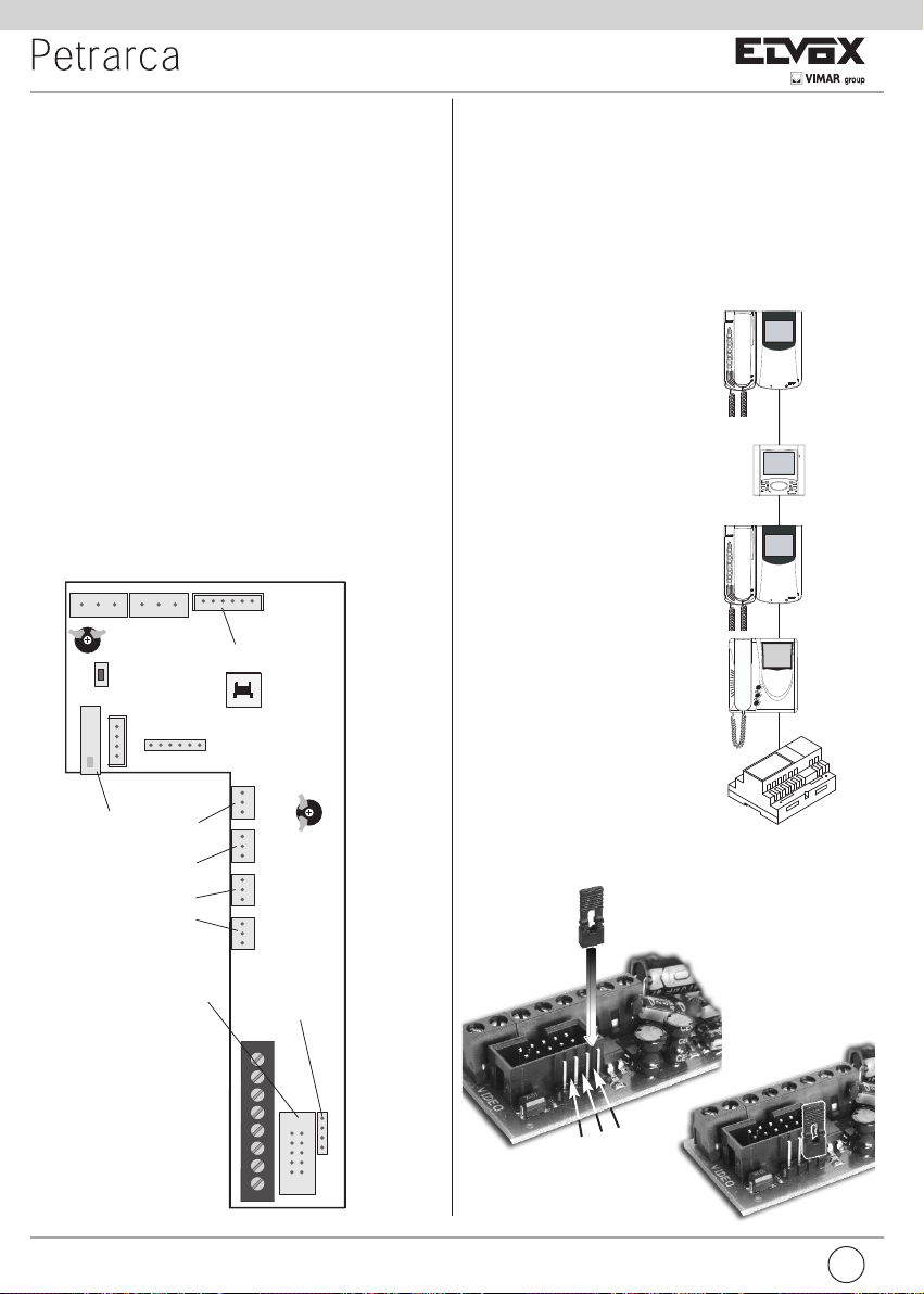
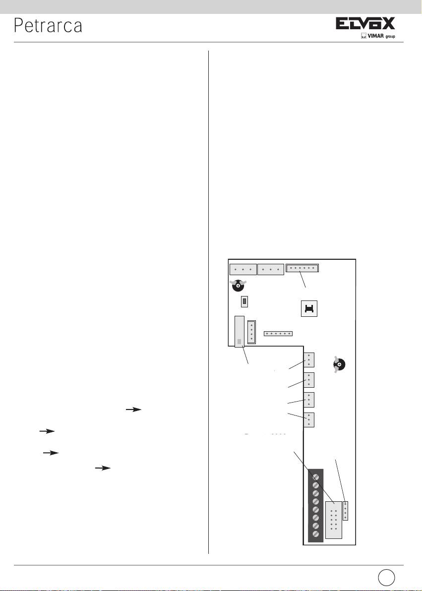
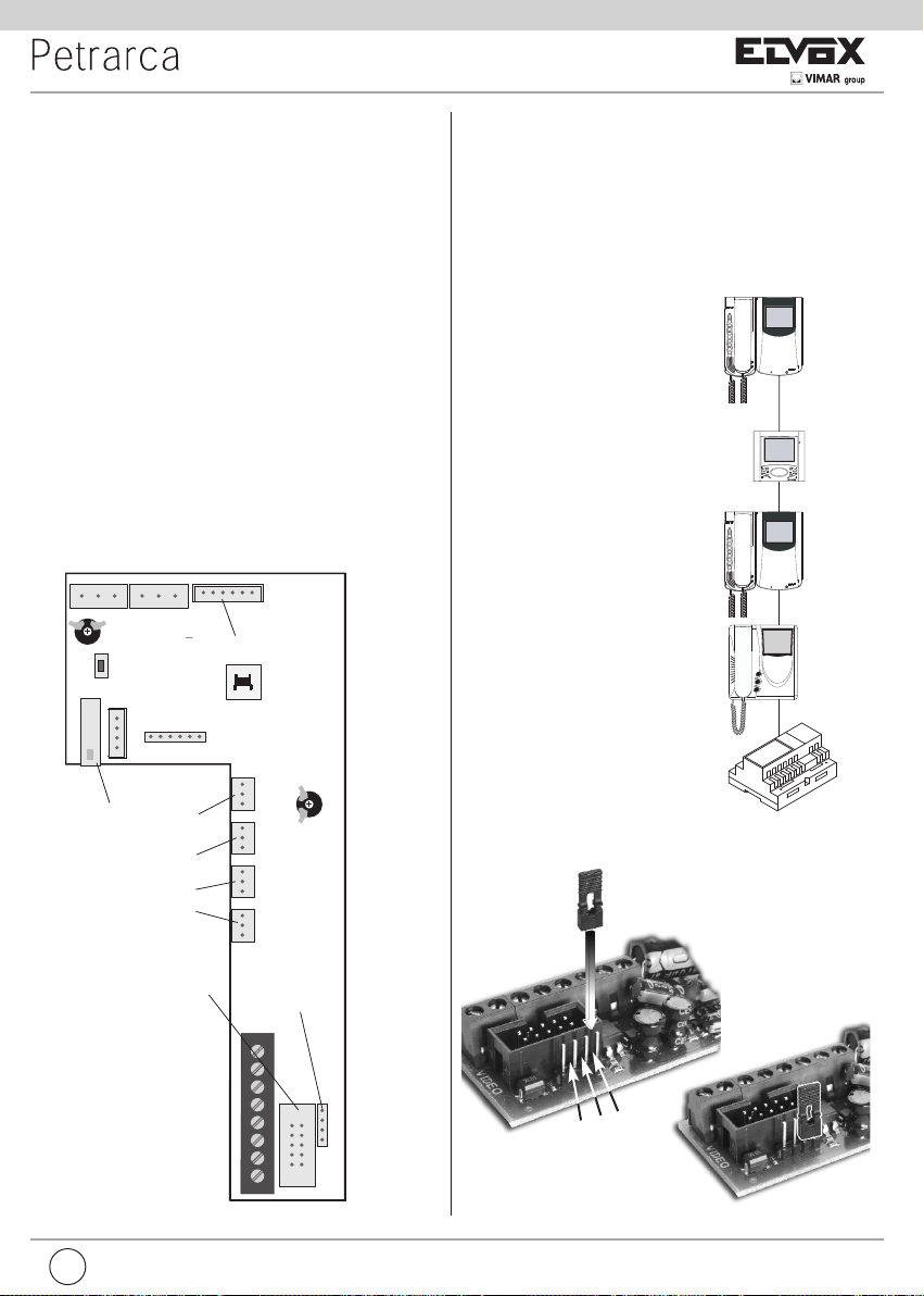
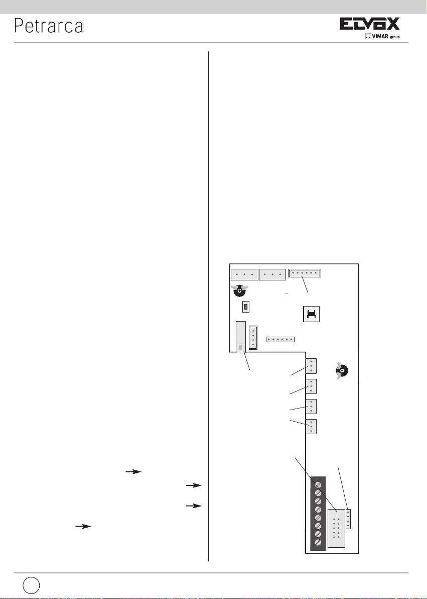
Morsettiera di collegamento e connettori
1, 2) Linea BUS.
4, 6P) Collegamento per pulsante di chiamata fuoriporta.
5, 6S) Collegamento suoneria supplementare.
-, +) Alimentazione supplementare per monitor con alimentatore art. 6923.
VARIAT.) Collegamento per modulo art. 6153/682.
VIDEO) Collegamento per monitor art. 6029 o 6029/C.
T1) 1° coppia di pulsanti art. 692P.
T2) 2° coppia di pulsanti art. 692P.
T3) 3° coppia di pulsanti art. 692P.
T4) 4° coppia di pulsanti art. 692P.
BL BIRO A+ CAA- VAR IAT.
SERR.
SERIALE
PRG.
T1
T2
T3
T4
VIDEO
1
1
2
4
5
6S
6P
-
+
T1
T2
T3
T4
Per art. 6153/682
RESET
SERRATURA
Per art. 6009 o
6009/C
Stabilizzazione
segnale video
TR1
TR2
Fig. 1
Fig. 3
Regolazioni
Il volume di chiamata è regolabile spostando il filo dell’altoparlante tra il connettore A+ (tono alto) e A- (tono basso), altrimenti utilizzare l’accessorio Art.
6153/682, lasciando il filo dell’altoparlante collegato al connettore A-.
INSTALLAZIONE
L’installazione del citofono da esterno parete non richiede accessori supplementari. È possibile comunque predisporre una scatola in verticale da 3 moduli
per agevolare il fissaggio e il passaggio dei cavi. Per l’installazione da tavolo e
in abbinamento al monitor vedere rispettivamente le istruzioni dei kit di trasformazione e dei monitor.
Terminazione Bus per stabilizzazione del
segnale video
All’interno del citofono è presente un “connettore di terminazione BUS” (A-B-C) per la
stabilizzazione del segnale video.
A seconda della configurazione di collegamento (citofoni/videocitofoni collegati in serie
o derivati ad un distributore) settare in ponticello sul connettore ABC come descritto
nella nota “Terminazione bus per impianti
DUE FILI ELVOX” riportata in seguito, nella
sezione schemi di collegamento.
Fig. 2
B
A
A
A
A
C
B
Per art. 6029
ou 6029/C
Page 3

I
3
PROGRAMMAZIONE
Le programmazioni del citofono sono di tre tipi: assegnazione codice identificativo o codice di chiamata (indispensabile), assegnazione codice identificativo secondario (per citofoni associati ad un citofono di capo gruppo),
programmazione pulsanti per servizi ausiliari e chiamate intercomunicanti
(dove necessario). Le programmazioni devono essere effettuate con l’impianto
acceso, senza comunicazioni attive e solamente dopo aver collegato i citofoni/videocitofoni all’impianto e programmato le targhe.
Programmazione codice identificativo
Il codice identificativo va programmato per mezzo di una targa (principaleMASTER), presente nell’impianto e già configurata. Il citofono viene fornito
senza codice identificativo assocciato. Per verificare ciò premere il pulsante
serratura e il citofono emetterà un triplo “Bip”.
Attenzione: durante la programmazione del codice di identificazione del
citofono/videocitofono si hanno a disposizione 30 secondi dal momento
in cui si entra in programmazione nel citofono/videocitofono al momento
in cui si preme il pulsante di chiamata sulla targa o si invia il codice.
Fase di programmazione:
1) Togliere il coperchio del citofono.
2) Premere e mantenere premuto il pulsante RESET presente nel citofono.
3) Premere e mantenere premuto la lamella corrispondente al pulsante
serratura assieme al pulsante RESET.
4) Rilasciare il pulsante RESET, continuando a tenere premuto il pulsante
serratura.
5) Dopo 2 secondi il citofono emette un tono acuto e viene messo in comunicazione con la targa. Se al citofono è collegato anche il monitor,
quest’ultimo viene acceso e connesso alla telecamera della targa.
6) Rilasciare la lamella corrispondente alla serratura.
7) Nelle targhe a pulsanti premere il pulsante di chiamata corrispondente
al citofono, invece nelle targhe alfanumeriche comporre il codice di
chiamata e premere il pulsante “ ”.
8) Se nell’impianto esiste già un citofono con lo stesso codice identificativo associato, la targa emette un segnale sonoro basso ed è necessario ripetere l’operazione dal punto 2.
9) In caso contrario il codice viene associato al citofono e la comunicazione viene terminata.
Programmazione codice identificativo secondario
La programmazione del codice identificativo secondario è richiesta solamente
quando si vuole far suonare contemporaneamente più di un citofono con lo
stesso pulsante o codice di chiamata. I citofoni che devono suonare contemporanemente vengono associati ad uno stesso gruppo. Il citofono “capogruppo” viene programmato per primo attraverso la precedente procedura
“programmazione codice identificativo”, invece i citofoni aggiuntivi del gruppo
vengono programmati con il codice identificativo secondario (vedi tabella riportata nella sezione schemi di collegamento). Il numero di citofoni che si possono associare ad uno stesso gruppo, senza l’ausilio del programmatore art.
950C o SaveProg, sono 3 più un capogruppo.
Nel caso che ai citofoni siano abbinati i monitor Petrarca, è necessario
aggiungere un alimentatore supplementare art. 6923 per ogni monitor
aggiuntivo dopo il secondo monitor. Utilizzando il programmatore art.
950C, è possibile programmare l’attivazione della suoneria di tutti i videocitofoni senza far accendere contemporaneamente tutti i monitor per
poi accendere il monitor, dal videocitofono da cui si risponderà con il pulsante di autoaccensione; ciò permette di non utilizzare alimentatori supplementari.
Fase di programmazione:
1) Togliere il coperchio del citofono.
2) Premere e mantenere premuto il pulsante RESET presente nel citofono.
3) Premere e mantenere premuti la lamella corrispondente al pulsante serratura e il pulsante di autoinserimento/autoaccensione (il 1° pulsante sotto
alla lamella), assieme al pulsante RESET.
4) Rilasciare il pulsante RESET, continuando a tenere premuti gli altri 2 pulsanti.
5) Dopo 2 secondi il citofono emette un tono acuto e viene messo in comunicazione con la targa. Se al citofono è collegato anche il monitor,
quest’ultimo viene acceso e connesso alla telecamera della targa.
6) Rilasciare la lamella corrispondente alla serratura e il pulsante di autoinserimento/autoaccensione.
7) Nelle targhe a pulsanti premere il pulsante di chiamata corrispondente al citofono
di “capogruppo”, invece nelle targhe alfanumeriche comporre lo stesso codice
di chiamata del citofono di “capogruppo” e premere il pulsante “ ”.
8) Associato l’identificativo secondario al citofono, la comunicazione viene terminata.
Per conoscere il numero assegnato fare riferimento alla tabella riportata nella sezione schemi di
collegamento.
Programmazione pulsanti
Il citofono viene fornito con una coppia di pulsanti aggiuntivi art. 692P, per le funzioni di autoinserimento/autoaccensione e per il servizio ausiliario “luce scale”, il quale attiva il 1° relè del 1° attuatore
(art. 69RH), se collegato all’impianto. È possibile inserire nel citofono altre 3 coppie di pulsanti art.
692P, da collegare ai connettori T2-T3-T4, ai quali corrispondo le seguenti funzioni di default.
Pulsante Connettore In program. Funzione di default
1° T1 P1 Autoinserimento
/autoaccensione
2° T1 P2 Luce scale (1° relè del 1° attuatore, art.
69RH)
3° T2 P3 Ausiliario (2° relè del 1° attuatore, art.
69RH)
4° T2 P4 Non associato
5° T3 P5 Non associato
6° T3 P6 Non associato
7° T4 P7 Funzione F1 della targa
8° T4 P8 Funzione F2 della targa
Il tasto serratura è P0.
Per cambiare il tipo di funzionamento dei pulsanti P0 e P1 è necessario utilizzare il programmatore
art. 950C o il Software Save Prog.
Programmazione pulsanti per chiamate intercomunicanti
Fase di programmazione:
1) Sganciare il microtelefono del citofono/videocitofono da chiamare, se della serie 8870,
Giotto,Petrarca. Per tutte le versioni della serie 6600 (senza microtelefono), premere e
tenere premuto il tasto parla/ascolta .
2) Togliere il coperchio del citofono da programmare.
3) Premere e mantenere premuto il pulsante RESET presente nel citofono da programmare.
4) Premere e mantenere premuto il pulsante supplementare per eseguire la chiamata interco-
municante assieme al pulsante RESET.
5) Rilasciare il pulsante RESET, continuando a tenere premuto il pulsante di chiamata.
6) Dopo 2 secondi il citofono emette un tono acuto, mentre l’altro citofono emette una scala tri-
tonale ascendente.
7) Rilasciare il pulsante relativo alla chiamata intercomunicante.
8) Premere nel citofono chiamato (quello con il suono tritonale), uno dei pulsanti programmati
(come serratura, F1, F2 o attuatore).
9) Un tono acuto conferma la fine della procedura.
Ripetere la stessa procedura anche per gli altri citofoni ed eventuali pulsanti di chiamata intercomunicante.
Programmazione pulsante autoaccensione verso targa specifica.
Fase di programmazione:
1) Togliere il coperchio del citofono.
2) Premere e mantenere premuto il pulsante RESET presente nel citofono.
3) Premere e mantenere premuto il pulsante supplementare per eseguire l’autoaccensione as-
sieme al pulsante RESET
4) Rilasciare il pulsante RESET, continuando a tenere premuto il pulsante autoaccensione.
5) Dopo 2 secondi il citofono emette un tono acuto.
6) Rilasciare il pulsante relativo all’autoaccensione.
7) Nelle targhe a pulsanti premere il pulsante di chiamata corrispondente al citofono, invece nelle
targhe alfanumeriche comporre il codice di chiamata e premere il pulsante “ ”.
8) Un tono acuto conferma la fine della procedura.
Riprogrammazione valore di default dei pulsanti (P2,P3,P4,P5,P6,P7,P8)
Fase di programmazione:
1) Togliere il coperchio del citofono.
2) Premere e mantenere premuto il pulsante RESET presente nel citofono.
3) Premere e mantenere premuto il pulsante interessato da riprogrammare assieme
al pulsante RESET.
4) Rilasciare il pulsante RESET, continuando a tenere premuto l’altro pulsante.
5) Dopo 2 secondi il citofono emette un tono acuto.
6) Rilasciare il pulsante da riportare a default e ripremerlo.
Cancellazione totale delle programmazioni.
Fase di programmazione:
Questa procedura è consigliata quando si vuole cambiare l’ID di un citofono/videocitofono precedentemente programmato e non si vuole mantenere la programmazione di funzionamento dell’apparecchio.
1) Togliere il coperchio del citofono.
Page 4
4
GB
DESCRIPTION
Type 6209 is an interphone in the Petrarca series for ELVOX 2-WIRE audio
and video door entry systems. It is supplied as standard with 3 pushbuttons,
one for lock release, one for self-start of the interphone in the system even
when not called, and one for the auxiliary “stair light” service. The interphone
can be fitted with an additional 3 pairs of pushbutton types 692P (692P/M or
692P/R), for auxiliary services or intercommunicating calls, and the accessory
type 6153/682 for: call volume adjustment, call signal mute, call denied luminous indicators, signal to indicate unanswered calls, signal to indicate services not available and luminous signal for gate/door open. The interphone can
be installed as a wall-mounted version or desktop using the conversion kit
type 6140 or 6A40, or in combination with monitors in the Petrarca series type
6029 (b/w monitor) or type 6029/C (colour monitor) by means of wall bracket
type 6145 or desktop conversion kit type 6142 or 6A42.
Connection and connector terminal board
1, 2) BUS line.
4, 6P) Connection for door call pushbutton.
5, 6S) Connection of additional door ringtone
-, +)
Additional power supply for monitor with power supply type 6923.
VARIAT.) Connection for module type 6153/682.
VIDEO) Connection for monitor type 6029 or 6029/C.
T1) 1st pair of pushbuttons type 692P.
T2) 2nd pair of pushbuttons type 692P.
T3) 3rd pair of pushbuttons type 692P.
T4) 4th pair of pushbuttons type 692P
.
2) Premere e mantenere premuto il pulsante RESET presente nel citofono.
3) Premere e mantenere premuto il pulsante di autoaccensione assieme al
pulsante RESET.
4) Rilasciare il pulsante RESET, continuando a tenere premuto il pulsante
autoaccensione.
5) Dopo 2 secondi il citofono emette, per 2 secondi, un tono lungo.
6) Rilasciare il pulsante autoaccensione.
7) Durante il tono lungo, premere la lamella del pulsante serratura.
Se la procedura di cancellazione è andata a buon fine, premendo nuovamente
la lamella della serratura il citofono emetterà un triplo “Bip”.
FUNZIONAMENTO
Le chiamate da targa esterna, intercomunicante e fuoriporta sono differenziate tra loro da toni diversi.
Chiamata da targa.
Le chiamate da targa non seguono la pressione del pulsante di chiamata ma
vengono generate internamente dal citofono. Il periodo di chiamata è 1 s di
suono e 2 s di pausa ripetuto per 2 volte (valore di default impostato nella
targa). Per rispondere, sollevare il microtelefono. Se il microtelefono è già sollevato durante la chiamata riagganciare e risollevarlo. Il tempo di risposta alla
chiamata (30 s) e il tempo di conversazione (2 minuti di default) sono impostati
nei parametri della targa. Scaduto il tempo di conversazione, si può continuare, senza riagganciare il microtelefono, se viene eseguita di nuovo la chiamata entro 10 s dalla stessa targa.
Chiamata intercomunicante.
Sollevare il microtelefono del citofono, premere il pulsante intercomunicante
relativo al citofono/videocitofono da chiamare. Nel microtelefono del citofono
chiamante si udrà un tono di chiamata (se la chiamata è possibile) o tono di
occupato (se la chiamata non è possibile). Nel citofono chiamato la suoneria
inizierà a suonare ciclicamente con un ritmo di 1 s di suono e 4 s di pausa. La
durata massima della chiamata sarà di 30 s (6 cicli). Per rispondere alla chiamata è sufficiente sollevare il microtelefono; la durata massima della conversazione è di 5 minuti. Scaduto il tempo di conversazione si può continuare la
conversazione, senza riagganciare il microtelefono, se viene eseguita di nuovo
la chiamata entro 10 s. Un’eventuale chiamata da targa ha priorità su quella
intercomunicante.
Chiamate rifiutate.
L’installazione dell’art. 6153/682 nel citofono, permette di variare l’intensità di
chiamata o di escludere il suono di chiamata. L’esclusione della chiamata è indicata dall’accensione permanente del LED rosso. Se vengono eseguite delle
chiamate verso il citofono quando è in condizione di chiamata esclusa, queste vengono rifiutate. Il rifiuto delle chiamate determina un breve spegnimento
del LED rosso tante volte sono le chiamate escluse (massimo chiamate
escluse 4). La segnalazione viene ripetuta ogni 10 s circa. La cancellazione
delle chiamate rifiutate avviene con: la riabilitazione della suoneria, con il reset
del citofono o l’assenza di alimentazione nell’impianto. Nelle targa il rifiuto è
segnalato con il tono dissuasione (una serie di “Bip” di 100ms con pausa di
100ms per 5 totali). Nella targa con display viene anche visualizzato il messaggio “Non disturbare”.
Tasto Serratura
Il tasto serratura di ogni apparecchio funziona nel modo seguente.
- Apparecchio con microtelefono a riposo serratura verso l’ultima
targa con la quale ha parlato o dalla quale è stato chiamato.
- Apparecchio con microtelefono sollevato ma non impegnato in conversa-
zione chiamata a centralino se il flag Centralino è SI. Altrimenti si
riconduce al primo caso.
- Apparecchio con microtelefono sollevato e impegnato in conversazione
interna come il primo caso.
- Apparecchio con microtelefono sollevato e impegnato in conversazione
esterna o chiamato da targa serratura verso la targa con la quale
sta parlando o dalla quale è chiamato.
In pratica si va ad azionare una serratura sempre tranne quando si alza il microtelefono e si preme subito il pulsante serratura. Portare anche questo al
caso standard si può se nell’impianto non c’è il centralino di portineria e se si
pone il flag Centralino a NO.
BL BIRO A+ CAA- VAR IAT.
SERR.
SERIALE
PRG.
T1
T2
T3
T4
VIDEO
1
1
2
4
5
6S
6P
-
+
T1
T2
T3
T4
Per art. 6153/682
RESET
SERRATURA
Per art. 6009 o
6009/C
Stabilizzazione
segnale video
TR1
TR2
Video signal
stabiliser
For
Lock
TR1, TR2) Do not touch, trimmers already set by the firm.
Fig. 1
Per type 6029
ou 6029/C
Page 5
GB
5
Controls
The call volume can be adjusted by moving the loudspeaker wire from connector A+ (high) to A- (low); otherwise use accessory type 6153/682, leaving
the loudspeaker wire connected to connector A-.
INSTALLATION
Wall-mounted installations of the interphone do not require additional accessories. However a vertical 3-module box may be used to facilitate fixture and
cable routing. For desktop installations and combinations with monitors, refer
to the respective instructions of the conversion kit or monitor.
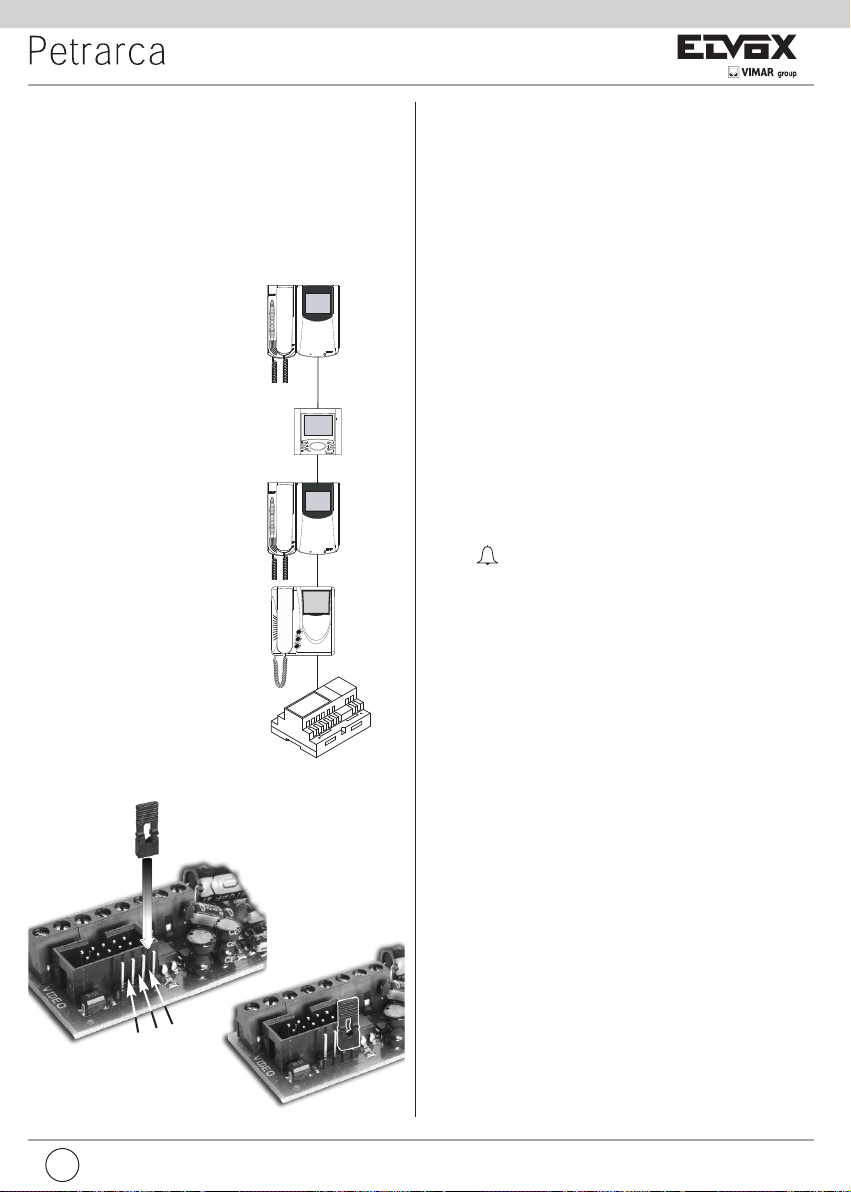
Bus termination for video signal stabilisation
The interphone is provided with a “BUS termination connector” (A-B-C) for video signal
stabilisation.
Depending on the connection configuration
(interphones/monitors connected in series or
derived from a distributor), set a jumper on the
connector ABC as described in the note “Bus
termination for ELVOX TWO-WIRE INSTALLATIONS” in the wiring diagrams section below.
Fig. 2
B
A
A
A
Fig. 3
A
C
B
PROGRAMMING
There are three interphone programming modes: assignment of an identification code or call code (indispensable), assignment of a secondary identification code (for interphones associated with a master interphone), programming
of pushbuttons for auxiliary services and intercommunicating calls (when necessary).
Programming must be performed with the system switched on, without active
communication and only after connecting the interphones/monitors to the system and programming the panels.
Identification code programming
The identification code is programmed via an entrance panel (MASTER), already configured and present on the system. The interphone is supplied without associated identification code. To verify this condition, press the lock
release pushbutton and the interphone should emit a triple “Beep”.
Attention: during the interphone/video interphone identification code programming you have 30 seconds from the moment you enter the programming in the interphone/video interphone and the moment you press
the call push-button on the panel or you send the code.
Programming phase:
1) Remove the interphone cover.
2) Press and hold the RESET pushbutton on the interphone.
3) Press and hold the tab on the lock release pushbutton, together with the
RESET pushbutton.
4) Release the RESET pushbutton, keeping the lock release pushbutton
pressed.
5) After 2 seconds the interphone emits a high tone and communication is
enabled with the panel. If the monitor is also connected to the interphone,
it is switched on and connected to the camera of the entrance panel.
6) Release the tab of the lock release pushbutton.
7) On pushbutton entrance panels, press the call button for the interphone,
while on alphanumeric keypads, enter the call code and press pushbut-
ton “ ”.
8) If the system contains an interphone that already has the same associated identification code, the panel emits a low signal and the operation
should be repeated from point 2.
9) Otherwise the code is associated with the interphone and communication
is terminated.
Secondary identification code programming
Programming of the secondary identification code is only required when more
than one interphone is to be called by means of the same pushbutton or call
code. The interphones that ring at the same time are associated with the same
group. The “master” interphone is programmed first by means of the “identification code programming” procedure described above, while the additional
group interphones are programmed with the secondary identification code
(see table shown in the wiring diagram section).
A maximum of three audio door entry units plus one group master can be
associated with the same group, without the need for programmer Type
950C or SaveProg .
If the interphones are combined with Petrarca monitors, an additional
power supply type 6923 must be fitted for each additional monitor after
the second monitor. Using programmer type 950C, activation of the ringtone on all monitors can be programmed, without simultaneous activation of all monitors, to then enable activation of the monitor from the
interphone used to answer the call with the self-start pushbutton; this
avoids the need to use additional power supplies.
Programming phase:
1) Remove the interphone cover.
2) Press and hold the RESET pushbutton on the interphone.
3) Press and hold the tab on the lock release pushbutton and the self
start/auto-activation pushbutton (the first pushbutton below the tab), together with the RESET pushbutton.
4) Release the RESET pushbutton, keeping the other two pushbuttons
pressed.
5) After 2 seconds the interphone emits a high tone and communication is
enabled with the panel. If the monitor is also connected to the interphone, it is switched on and connected to the camera of the entrance
panel.
6) Release the tab on the lock release pushbutton and the self start pu-
shbutton.
Page 6

6
GB
7) On pushbutton entrance panels, press the call button for the “master” interphone, while on alphanumeric keypads, enter the call code of the “master” in-
terphone and press pushbutton “ ”.
8) When the secondary code is associated with the interphone and communication is terminated.
To know the number assigned see table shown in the wiring diagram section.
Pushbutton programming
The interphone is supplied with a pair of additional pushbuttons type 692P, for the
functions self start and the auxiliary service “stair light”, which activates the 1st
relay of the 1st actuator (type 692R), if connected to the system. A further three
pairs of pushbuttons type 692P can be inserted in the interphone, to be connected
to connectors T2-T3-T4, corresponding to the following default functions.
Pushbutton Connector In program. Default function
1° T1 P1 Self-start
2° T1 P2 Stair light (1st relay of 1st a c -
tuator, type 692R)
3° T2 P3 Auxiliary (2nd relay of 1st actua-
tor, type 692R)
4° T2 P4 Not associated
5° T3 P5 Not associated
6° T3 P6 Not associated
7° T4 P7 Function F1 on panel
8° T4 P8 Function F2 on panel
P0 is the lock button.
To change the operating mode of buttons P0 and P1, use programmer type 950C
or the Save Prog software.
Intercommunicating call pushbutton programming
Programming phase:
1) Raise
the handset of theinterphone/video interphone to call(when using
series 8870, Giotto, Petrarca). With other versions ofseries 6600 (without
handset) press and keep pressed the talk/listen push-button .
2) Remove the cover of the interphone to be programmed.
3) Press and hold the RESET push-button on the audio door entry unit to pro-
gram.
4) Press and hold the additional pushbutton to make the intercommunicating
call together with the RESET pushbutton.
5) Release the RESET pushbutton, keeping the call pushbutton pressed.
6) After 2 seconds the interphone emits a high tone, while the other interphone
emits a 3-tone ascending scale.
7) Release the intercommunicating call pushbutton.
8) On the interphone called (with the 3-tone ring), press one of the programmed
pushbuttons (such as lock, F1, F2 or actuator).
9) A high tone confirms the end of the procedure.
Repeat the same procedure for the other interphones and any other intercommunicating call pushbuttons.
Programming the self-start pushbutton to a specific panel.
Programming phase:
1) Remove the interphone cover.
2) Press and hold the RESET pushbutton on the interphone.
3) Press and hold the additional pushbutton to activate the self-start function to-
gether with the RESET pushbutton.
4) Release the RESET pushbutton, keeping the self-start pushbutton pressed.
5) After 2 seconds the interphone emits a high tone.
6) Release the self-start pushbutton.
7) On pushbutton entrance panels, press the call button for the interphone, while
on alphanumeric keypads, enter the call code and press pushbutton “ ”.
8) A high tone confirms the end of the procedure.
Restoring default values of pushbuttons (P2,P3,P4,P5,P6,P7,P8)
Programming phase:
1) Remove the interphone cover.
2) Press and hold the RESET pushbutton on the interphone.
3) Press and hold the relative pushbutton to be reprogrammed together with the
RESET pushbutton.
4) Release the RESET pushbutton, keeping the other pushbutton pressed.
5) After 2 seconds the interphone emits a high tone.
6) Release the pushbutton to restore to default and then press again.
Deleting all settings.
Programming phase:
This procedure is advised when you want to change the ID of an interphone/monitor previously programmed and you do not want keep the operation
programming of the appliance.
1) Remove the interphone cover.
2) Press and hold the RESET pushbutton on the interphone.
3) Press and hold the self start pushbutton together with the RESET pu-
shbutton.
4) Release the RESET pushbutton, keeping the self-start pushbutton pressed.
5) After 2 seconds the interphone emits a continuous tone for two seconds.
6) Release the self-start pushbutton.
7) During the continuous tone, press the tab on the lock release pushbutton.
If the deletion procedure is successful, when the lock release tab is pressed
once more the interphone emits a triple “Beep”.
OPERATION
Calls from an entrance panel, intercommunicating calls and door calls are differentiated by means of different tones.
Door calls.
Calls from entrance panels do not follow the pressed pushbutton but are generated inside the interphone. The call interval is 1 s of ringtone and 2 s of pause
repeated twice (default value set on panel). To answer, raise the handset. If the
handset is already raised during the call, replace and raise it again. The call answer time (30 s) and the conversation time (2 minutes by default) are set in the
panel parameters. When the conversation time has elapsed, the user can continue without replacing the handset if a new call is made within 10 s from the
same panel.
Intercommunicating call.
Lift the handset and press the intercommunicating button for the interphone/monitor to be called. On the handset of the interphone called a call tone
will ring (if the call is enabled) or an engaged tone (if not enabled). On the called interphone the ringtone starts sequentially at intervals of 1 s ringing and 4 s
pause. The maximum duration of the call is 30 s (6 cycles). To answer the call,
simply raise the handset; the maximum duration of the conversation is 60 seconds. When the conversation time has elapsed, the user can continue without
replacing the handset if a new call is made within 10 s. Calls from the panel
have priority over intercommunicating calls.
Denied calls.
Installation of type 6153/682 in the interphone, enables the user to vary the call
intensity or mute the ringtone. Call mute is indicated by permanent illumination
of the red LED. If calls are made to the interphone when the call mute is enabled, they are denied. A denied call causes the red Led to briefly switch off according to the number of times calls are denied (maximum 4 denied calls). The
signal is repeated every 10 s (approx.). Deletion of denied calls is by: reenabling
the ringtone, resetting the interphone or a system power failure. On the panel,
a denied call is indicated by means of a dissuasion tone (a series of “Beeps” at
100ms intervals with a pause of 100ms for a total of 5 s).
The message “Do not disturb” also appears on panels with display.
Lock Button
The lock button of each device works in the following manner.
- Device with handset at rest lock to the last entrance panel with
which it has spoken or from which it has been called.
- Device with handset raised but not engaged in a conversation call
to switchboard if the Switchboard flag is YES. Otherwise it goes back to
the first case.
- Device with handset raised and engaged in an internal conversation
as in the first case.
- Device with handset raised and engaged in an external conversation or
called from entrance panel lock to the entrance panel being spo-
ken with or from which it has been called.
In practice a lock is always activated except when the handset is raised and you
immediately press the lock button. This can also be taken to the standard case
if the system has no porter switchboard and the Switchboard flag is set on NO.
Page 7
F
7
DESCRIPTION
L'art. 6209 est un portier audio de la série Petrarca pour systèmes de portiers audio ou vidéo 2 FILS ELVOX. Livré avec 3 boutons de série : un pour
la commande de la gâche, un pour l'allumage/extinction automatique du
poste même sans appel et un pour le service auxiliaire d'éclairage escalier. Le
portier audio peut recevoir 3 autres paires de boutons art. 692P (692P/M o
692P/R) pour les services auxiliaires ou la communication entre postes et l'accessoire art. 6153/682 pour : réglage du volume d'appel, exclusion du signal
d'appel, signalisation lumineuse d'appel exclu, signalisation d'appel sans réponse et signalisation de services non disponibles et signalisation lumineuse
de porte ouverte/portail ouvert. L'installation du portier audio est réalisable
en version murale ou en version de table à l'aide des kits de transformation
art. 6140 ou 6A40 ou bien en combinaison avec les moniteurs de la série Petrarca art. 6029 (moniteur N/B) ou art. 6029/C (moniteur couleur) à l'aide de
la patte de support mural art. 6145 ou du kit de transformation version de
table art. 6142 ou 6A42.
Bornier de connexion et connecteurs
1, 2) Ligne BUS.
4, 6P) Raccordement pour bouton-poussoir d'appel de palier
5, 6S) Raccordement sonnerie supplémentaire.
-, +) Alimentation supplémentaire pour moniteurs art. 6923.
VARIAT.) Raccordement pour module art. 6153/682.
VIDEO) Raccordement pour moniteur art. 6029 ou 6029/C.
T1) 1ère paire de boutons art. 692P.
T2) 2ème paire de boutons art. 692P.
T3) 3ème paire de boutons art. 692P.
T4) 4ème paire de boutons art. 692P.
Réglages
Le volume d'appel est réglable en déplaçant le fil du haut-parleur entre le connecteur A+ (ton haut) et A- (ton bas), sinon utiliser l'accessoire art. 6153/682
en laissant le fil du haut-parleur relié au connecteur A-.
INSTALLATION
L'installation en saillie du portier audio ne nécessite pas d'accessoires supplémentaires. Toutefois, il est possible de prévoir une boîte 3 modules verticale
pour faciliter la fixation et le passage du câblage. Pour l'installation de la version de table en combinaison avec le moniteur, voir respectivement les instructions des kits de transformation et des moniteurs.
Terminaison Bus pour la stabilisation du signal vidéo
Un « connecteur de terminaison bus » (A-BC) se trouve à l'intérieur de l'interphone pour
la stabilisation du signal vidéo.
En fonction de la configuration de la connexion (interphones/moniteurs reliés en série ou
dérivés à un distributeur), régler en pontet sur
le connecteur ABC comme décrit dans la note
« Terminaison bus pour installations DEUX
FILS ELVOX » reportée ci-dessous, dans la
section schémas de raccordement.
BL BIRO A+ CAA- VAR IAT.
SERR.
SERIALE
PRG.
T1
T2
T3
T4
VIDEO
1
1
2
4
5
6S
6P
-
+
T1
T2
T3
T4
Per art. 6153/682
RESET
SERRATURA
Per art. 6009 o
6009/C
Stabilizzazione
segnale video
TR1
TR2
Pour
Fig. 1
Fig. 2
B
A
A
A
Fig. 3
A
C
B
Stabilisateur de
signal vidéo
TR1, TR2) Trimmers déjà reglés dans l’usine, ne toucher pas.
Gãche
Pour Art. 6029
ou 6029/C
Page 8
8
F
Programmation des boutons
Le portier est fourni avec une paire de boutons supplémentaires art. 692P pour les
fonctions d'auto-enclenchement/auto-allumage et pour le service auxiliaire d'éclairage escalier, lequel active le 1er relais du 1er actionneur (art. 69RH), si connecté
au système. Il est possible en outre de prévoir trois autres paires de boutons art.
692P à relier aux connecteurs T2-T3-T4, auxquels sont associées les fonctions
par défaut ci-après.
Bouton Connecteur Prog. Fonction par défaut
1er T1 P1 Auto-enclenchement/auto-allumage
2ème T1 P2 Éclairage escalier (1er relais du 1er
actionneur, art. 692R)
3ème T2 P3 Auxiliaire (2ème relais du 1er
actionneur, art. 692R)
4ème T2 P4 Non associé
5ème T3 P5 Non associé
6ème T3 P6 Non associé
7ème T4 P7 Fonction F1 de la plaque de rue
8ème T4 P9 Fonction F2 de la plaque de rue
P0 est la touche gâche.
Pour changer le type de fonctionnement des boutons P0 et P1, il est nécessaire
d'utiliser le programmateur art. 950C ou le logiciel Save Prog.
Programmation des boutons pour communication entre postes
Étapes de la programmation:
1) Décrocher
le combiné du poste d’appartement/portier-vidéo (lorsqu’on
utilise la série 8870,Giotto, Petrarca). Dans lesautres versions de lasérie
6600 (sans combiné) appuyer et maintenir enfoncé le poussoir
parle/écoute .
2) Déposer la face avant du portier audio à programmer.
3) Appuyer sans relâcher sur le bouton RESET de l’interphone à programmer.
4) Appuyer et garder le doigt sur le bouton de communication entre postes supplémentaire, en même temps que le bouton RESET.
5) Relâcher le bouton RESET tout en continuant à maintenir enfoncé le bouton
d'appel.
6) Après 2 secondes, le portier audio émet une tonalité aiguë, tandis que l'autre portier audio émet une échelle triton ascendante.
7) Relâcher le bouton de communication entre postes.
8) Appuyer sur un des boutons programmés (comme gâche, F1, F2 ou actionneur) du portier audio appelé (celui qui émet le son triton).
9) Une tonalité aiguë confirme la fin de la procédure.
Répéter aussi la même procédure pour les autres portiers audio et éventuels boutons d'appel pour communication entre deux postes.
Programmation du bouton d'auto-allumage vers la plaque de rue spécifique.
Étapes de la programmation:
1) Déposer la face avant du portier audio.
2) Appuyer et garder le doigt sur le bouton RESET du portier audio.
3) Appuyer et garder le doigt sur le bouton d'auto-allumage supplémentaire, en
même temps que le bouton RESET
4) Relâcher le bouton RESET tout en continuant à maintenir enfoncé le bouton
d'auto-allumage.
5) Le portier audio émet une tonalité aiguë après 2 secondes.
6) Relâcher le bouton d'auto-allumage.
7) Appuyer sur le bouton d'appel correspondant au portier audio sur les pla-
ques de rue à boutons. Taper le code d'appel et appuyer sur le bouton “
” sur les plaques de rue alphanumériques.
8) Une tonalité aiguë confirme la fin de la procédure.
Reprogrammation de la valeur par défaut (autrement dit d'usine) des boutons (P2,P3,P4,P5,P6,P7,P8)
Étapes de la programmation:
1) Déposer la face avant du portier audio.
2) Appuyer et garder le doigt sur le bouton RESET du portier audio.
3) Appuyer et garder le doigt sur le bouton à reprogrammer, en même temps
que le bouton RESET.
4) Relâcher le bouton RESET tout en continuant à maintenir enfoncé l'autre bouton.
5) Le portier audio émet une tonalité aiguë après 2 secondes.
6) Relâcher le bouton à reprogrammer à la valeur par défaut et appuyer à nouveau sur celui-ci.
PROGRAMMATION
Les programmations du portier audio sont de trois types : assignation d'un code d'identification ou d'un code d'appel (indispensable), assignation d'un code d'identification secondaire (pour portiers audio associés à un portier audio "Master"), programmation des
boutons pour services auxiliaires et la communication entre postes (lorsque cela est
nécessaire). Les programmations doivent être effectuées avec le système allumé, sans
communication en cours et seulement après avoir relié les portiers audio et/ou vidéo au
système et programmé les plaques de rue.
Programmation du code d'identification
Le code d'identification doit être programmé par l'intermédiaire d'une plaque de rue
(principale-"MASTER"), montée dans le système et déjà configurée. Le portier audio
est fourni sans code d'identification associé. Pour vérifier cette condition, appuyer sur
le bouton de commande de la gâche. Le portier audio émettra un triple “Beep”.
Attention: pendant la programmation du code d’identification du poste d’appartement/portier-vidéo il y a 30 seconds du moment dans lequel on entre en programmation dans le poste d’appartement/portier-vidéo au moment dans lequel
on appuie sur le bouton-poussoir d’appel ou on envoie le code.
Étapes de la programmation:
1) Déposer la face avant du portier audio.
2) Appuyer et garder le doigt sur le bouton RESET du portier audio.
3) Appuyer et garder le doigt sur la lamelle correspondant au bouton de commande
de la gâche, en même temps que le bouton RESET.
4) Relâcher le bouton RESET tout en continuant à maintenir enfoncé le bouton de
commande de la gâche.
5) Après 2 secondes, le portier émet une tonalité aiguë et est mis en communication
avec la plaque de rue. Si le moniteur est également relié au portier audio, celui-ci
s'allume pour être connecté à la caméra de la plaque de rue.
6) Relâcher la lamelle correspondant à la gâche.
7) Appuyer sur le bouton d'appel correspondant au portier audio sur les plaques de
rue à boutons. Taper le code d'appel et appuyer sur le bouton II sur les plaques de
rue alphanumériques.
8) Si le système comprend déjà un portier audio avec le même code d'identification
associé, la plaque de rue émet un signal sonore faible et il faut nécessairement reprendre l'opération du point 2.
9) Dans le cas contraire, le code est associé au portier audio et la communication est
coupée.
Programmation du code d'identification secondaire
La programmation du code d'identification secondaire n'est requise que pour faire sonner simultanément plus d'un portier audio avec le même bouton ou code d'appel. Les
portiers audio qui doivent sonner simultanément sont associés à un même groupe. Le
portier audio "Master" est programmé en premier en utilisant la procédure précédente
de “programmation du code d'identification”, tandis que les portiers audio supplémentaires du groupe sont programmés avec le code d'identification secondaire (voir
table indiquée dans la section schémas de raccordement). Le nombre d’interphones
que l’on peut associer au même groupe, sans l’aide du programmateur art. 950C ou SaveProg, est 3 plus un chef de groupe.
Dans le cas de combinaison des portiers audio avec les moniteurs Petrarca, il faut
nécessairement ajouter une alimentation supplémentaire art. 6923 pour chaque
moniteur en plus du deuxième moniteur. Avec le programmateur art. 950C, il est
possible de programmer l'activation de la sonnerie de tous les portiers vidéo sans
allumer simultanément tous les moniteurs, pour allumer ensuite le moniteur du
portier audio, depuis lequel on reponara, appelé avec le bouton d'auto-allumage.
Cette solution permet ainsi de ne pas utiliser d'alimentations supplémentaires.
Étapes de la programmation :
1) Déposer la face avant du portier audio.
2) Appuyer et garder le doigt sur le bouton RESET du portier audio.
3) Appuyer et garder le doigt sur la lamelle correspondant au bouton de la gâche et
sur le bouton auto-enclenchement/auto-allumage (le 1er bouton sous la lamelle),
en même temps que le bouton RESET.
4) Relâcher le bouton RESET tout en maintenant enfoncés les deux autres boutons.
5) Après 2 secondes, le portier audio émet une tonalité aiguë et est mis en com-
munication avec la plaque de rue. Si le moniteur est également relié au portier
audio, celui-ci s'allume pour être connecté à la caméra de la plaque de rue.
6) Relâcher la lamelle correspondant à la gâche et le bouton d'auto-enclenche-
ment/auto-allumage.
7) Appuyer sur le bouton d'appel correspondant au portier audio "Master" sur les
plaques de rue à boutons. Taper le même code d'appel du portier audio "Master"
et appuyer sur le bouton “ ” sur les plaques de rue alphanumériques.
8) Une fois l'identificateur secondaire associé au portier audio, la communication
est coupée.
Pour connaître le numéro assigné voir référence dans la table indiquée dans la section
schémas de raccordement.
Page 9
D
9
BL BIRO A+ CAA- VAR IAT.
SERR.
SERIALE
PRG.
T1
T2
T3
T4
VIDEO
1
1
2
4
5
6S
6P
-
+
T1
T2
T3
T4
Per art. 6153/682
RESET
SERRATURA
Per art. 6009 o
6009/C
Stabilizzazione
segnale video
TR1
TR2
Effacement des programmations.
Étapes de la programmation:
Cette procédure est conseillée lorsqu’on veut changer l’ID d’un portier audio/portier
vidéo précédemment programmé et on ne veut pas maintenir la programmation de
fonctionnement de l’appareil.
1) Déposer la face avant du portier audio.
2) Appuyer et garder le doigt sur le bouton RESET du portier audio.
3) Appuyer et garder le doigt sur le bouton d'auto-allumage, en même temps que
le bouton RESET.
4) Relâcher le bouton RESET tout en continuant à maintenir enfoncé le bouton
d'auto-allumage.
5) Après 2 secondes, le portier audio émet une tonalité longue pendant 2 secondes.
6) Relâcher le bouton d'auto-allumage.
7) Pendant le retentissement de la tonalité longue, appuyer sur la lamelle du bouton de commande de la gâche.
Si la procédure d'effacement est réussie, le portier audio émettra de nouveau un triple “Beep” en appuyant sur la lamelle de la gâche.
FONCTIONNEMENT
Les appels de palier, de la plaque de rue et pour communication entre postes se distinguent par leur tonalité différente.
Appel de la plaque de rue.
Les appels de la plaque de rue ne répondent pas à la pression du bouton, mais sont
générés à l'intérieur par le portier audio. La période d'appel est de 1 s de tonalité et
de 2 s de pause, qui se répète deux fois (valeur par défaut définie dans la plaque de
rue). Pour répondre, décrocher le combiné. Si le combiné est déjà soulevé pendant
l'appel, le raccrocher puis le décrocher à nouveau. Le temps de réponse à l'appel
(30 s) et la durée de conversation (2 minutes par défaut) sont définies dans les paramètres de la plaque de rue. Une fois la durée de conversation écoulée, il est possible de continuer à dialoguer, sans raccrocher le combiné, si un autre appel est
effectué depuis la même plaque de rue dans les 10 s qui suivent.
Appel pour communication entre postes.
Décrocher le combiné du portier audio, appuyer sur le bouton de communication entre
postes du portier audio ou vidéo à appeler. Le combiné du portier audio appelant
émettra une tonalité d'appel (si l'appel est possible) ou une tonalité occupé (si l'appel
est impossible). La sonnerie du portier appelé commencera à retentir par séquences
répétitives de 1 s de tonalité et de 4 s de pause. La durée maximale de l'appel sera de
30 s (6 séquences). Pour répondre à l'appel, il suffit de soulever le combiné; la durée
maximale de la conversation est de 5 minutes. Une fois la durée de conversation écoulée, il est possible de continuer à dialoguer, sans raccrocher le combiné, si un visiteur
appelle de nouveau dans les 10 s qui suivent. Un appel éventuel depuis la plaque de
rue est prioritaire sur celui pour communication entre postes.
Appels refusés.
Le montage de l'art. 6153/682 dans le portier permet de varier le volume sonore de
l'appel ou d'exclure la tonalité d'appel. L'exclusion de l'appel est signalée par l'allumage (lumière fixe) de la LED rouge. Si des appels sont effectués vers le portier audio
lorsqu'il est en condition d'appel exclu, ceux-ci sont refusés. Le refus des appels
détermine une extinction de courte durée de la LED rouge pour chaque appel exclu
(4 au maximum). La signalisation est répétée environ toutes les 10 s. L'effacement
des appels refusés se produit : avec le rétablissement de la sonnerie, avec la réinitialisation du portier audio ou à défaut d'alimentation du système. Le refus, sur la plaque de rue, est signalé par la tonalité de dissuasion (une série de “Beep” de 100 ms
avec une pause de 100 ms pendant une durée totale de 5 s).Le message “Ne pas
déranger” apparaît en plus sur la plaque de rue avec moniteur.
Touche Gâche
La touche gâche de chaque appareil fonctionne de la manière suivante.
- Appareil avec combiné au repos gâche vers la dernière plaque
avec laquelle il a parlé ou à partir de laquelle il a été appelé.
- Appareil avec combiné soulevé mais non engagé en conversation
appel au standard si le flag Standard est OUI. Sinon, on retourne au premier cas.
- Appareil avec combiné soulevé et engagé en conversation interne
comme le premier cas.
- Appareil avec combiné soulevé et engagé en conversation externe ou
appel depuis plaque gâche vers la plaque avec laquelle il parle ou
depuis laquelle il est appelé.
En fait, on actionne toujours une gâche sauf lorsque l’on soulève le combiné et l’on appuie tout de suite sur le bouton gâche. Il est possible de le
mettre au cas normal si le standard de conciergerie est absent dans l’installation et l’on met le flag Standard à NON.
BESCHREIBUNG
Der Art. 6209 ist ein Haustelefon der Serie Petrarca für ELVOX DUE FILI Sprechanlagen und -Videosprechanlagen, das serienmäßig mit 3 Tasten ausgestattet ist: einer Türöffnertaste, einer Taste zur Selbsteinschaltung des Haustelefons
in der Anlage, auch wenn es nicht angerufen wurde, und einer Taste für die Zusatzfunktion “Treppenhausbeleuchtung”. Das Haustelefon kann um weitere 3
Tastenpaare Art. 692P (692P/M oder 692P/R) für Zusatzfunktionen oder interne
Rufe erweitert werden, sowie um das Zubehör Art.. 6153/682 für: Ruflautstärkeregelung, Rufsignalabschaltung, Leuchtanzeige für Rufabschaltung, Anzeige
unbeantworteter Rufe, Anzeige nicht verfügbarer Funktionen und Leuchtanzeige für Tür/Tor offen.
Das Haustelefon kann als Wandgerät installiert werden, oder mit Hilfe der Umbausätze Art. 6140 oder 6A40 als Tischgerät aufgestellt werden. In Kombination mit den Monitoren der Serie Pertrarca Art. 6029 (S/W-Monitor) oder Art.
6029/C (Farbmonitor) wird es mit der Wandhalterung Art. 6145 an der Wand installiert, oder mit Hilfe der Umbausätze Art. 6142 oder 6A42 als Tischgerät
aufgestellt.
Anschlussklemmenleiste und Steckverbinder
1, 2) BUS-Leitung.
4, 6P) Anschluss für Etagenruftaste.
5, 6S) Anschluss Zusatzläutwerk.
-, +) Zusatzversorgung für Monitor mit Netzgerät Art. 6923.
VARIAT.) Anschluss für Modul Art. 6153/682.
VIDEO) Anschluss für Monitor Art. 6029 oder 6029/C.
T1) 1. Tastenpaar Art. 692P.
T2) 2. Tastenpaar Art. 692P.
T3) 3. Tastenpaar Art. 692P.
T4) 4. Tastenpaar Art. 692P.
Abb. 1
Stabilisator des
Videosignals
Türöffner
Für
Für Art. 6029
oder 6029/C
Page 10

10
D
EINSTELLUNGEN
Die Ruflautstärke kann reguliert werden, indem der Draht des Lautsprechers
zwischen dem Steckverbinder A+ (lauter Ton) und A- (leiser Ton) umgesteckt
wird, andernfalls das Zubehör Art. 6153/682 benutzen und den Draht des
Lautsprechers am Steckverbinder A- angeschlossen lassen.
INSTALLATION
Für die Installation des Aufputz-Haustelefons ist kein zusätzliches Zubehör erforderlich. Es kann jedoch ein senkrechtes 3-Modul-Gehäuse verwendet werden, um die Befestigung und den Kabeldurchzug zu erleichtern. Für die
Installation als Tischgerät und in Kombination mit dem Monitor wird auf die Anleitungen der Umbausätze bzw. der Monitore verwiesen.
Busabschluss für die Stabilisierung des Videosignals
Im Videohaustelefon ist ein "Steckverbinder
BUS-Abschluss" (A-B-C) für die Stabilisierung
des Videosignals integriert.
Entsprechend der Anschlusskonfiguration
(Haus-/Videohaustelefone in Reihenschaltung
oder Ableitung eines Verteilers) ist lt. nachstehender Anmerkung "BUS-Abschluss für Anlagen DUE FILI ELVOX” im Abschnitt
Anschlusspläne ein Jumper am Steckverbinder ABC zu setzen.
PROGRAMMIERUNG
Es gibt drei Programmierungsarten des Haustelefons: Zuweisung des Kenncodes
oder Rufcodes (unbedingt notwendig), Zuweisung des zusätzlichen Kenncodes (für
Haustelefone, die mit einem Haupt-Haustelefon verbunden sind), Programmierung
der Tasten für Zusatzfunktionen und interne Rufe (sofern erforderlich). Die Programmierungen müssen mit eingeschalteter Anlage ohne aktive Kommunikationen
durchgeführt werden, und zwar erst, nachdem die (Video-)Haustelefone an die Anlage angeschlossen, und die Türstationen programmiert wurden.
Programmierung des Kenncodes
Der Kenncode wird mit Hilfe einer in der Anlage vorhandenen und bereits konfigurierten Türstation (Haupt-MASTER) programmiert. Das Haustelefon wird ohne zugewiesenen Kenncode geliefert. Um dies zu überprüfen, die Öffnertaste drücken:
das Haustelefon gibt einen dreifachen “Piepton” ab.
Achtung: während der Programmierung des ID-Codes des Haustelefons/Videohaustelefons betragen 30 Sekunden von dem Moment in dem
aufruft man die Programmierung beim Haustelefon/Videohaustelefon bis
zu dem Moment in dem wird die Ruftaste des Klingeltableaus gedrückt
oder der Code gesendet.
Programmierungsphase:
1) Die Abdeckung des Haustelefons abnehmen.
2) Die im Haustelefon befindliche RESET-Taste drücken und gedrückt halten.
3) Die Lamelle der Öffnertaste zusammen mit der RESET-Taste drücken und gedrückt halten.
4) Die RESET-Taste loslassen und die Öffnertaste weiterhin gedrückt halten.
5) Nach 2 Sekunden gibt das Haustelefon einen lauten Ton ab und wird mit der
Türstation in Kommunikation gesetzt. Wenn am Haustelefon auch ein Monitor
angeschlossen ist, wird dieser eingeschaltet und mit der Kamera der Türstation verbunden.
6) Die Lamelle der Öffnertaste loslassen.
7) Bei Klingeltableaus mit Knöpfen die Ruftaste drücken, mit der das Haustelefon gerufen wird, bei alfanumerischen Klingeltableaus den Rufcode eingeben
und die Taste “ ” drücken.
8) Wenn in der Anlage ein Haustelefon vorhanden ist, das bereits derselbe Kenncode zugewiesen wurde, gibt die Türstation einen leisen Ton ab und der Vorgang muss ab Punkt 2 wiederholt werden.
9) Andernfalls wird der Code dem Haustelefon zugewiesen und die Kommunikation beendet.
Programmierung des zusätzlichen Kenncodes
Die Programmierung des zusätzlichen Kenncodes ist nur erforderlich, wenn mit demselben Knopf bzw. Rufcode gleichzeitig mehrere Haustelefone läuten sollen. Die Haustelefone, die gleichzeitig läuten sollen, werden derselben Gruppe zugeordnet. Das
“Haupt-”Haustelefon wird zuerst mit der obigen Prozedur zur “Programmierung des
Kenncodes” programmiert, die Neben-Haustelefone derselben Gruppe werden mit dem
zusätzlichen Kenncode programmiert (siehe Tabelle auf Abschnitt der Schaltpläne).
Ohne Hilfe des Programmiergerätes Art. 950C oder mit SaveProg können 3 Haustelefone und ein Master-Gerät derselben Gruppe zugeordnet werden.
Wenn die Haustelefone mit den Monitoren Petrarca kombiniert sind, muss für
jeden zusätzlichen Monitor nach dem zweiten ein zusätzliches Netzgerät Art.
6923 hinzugefügt werden. Mit Hilfe des Programmierers Art. 950C kann die
Aktivierung des Läutwerks aller Videohaustelefone programmiert werden,
ohne gleichzeitig alle Monitore einzuschalten. Mit der Selbsteinschalttaste
wird dann der Monitor des Haustelefons eingeschaltet, an dem geantwortet
wird; dadurch wird vermieden, zusätzliche Netzgeräte zu benutzen.
Programmierungsphase:
1) Die Abdeckung des Haustelefons abnehmen.
2) Die im Haustelefon befindliche RESET-Taste drücken und gedrückt halten.
3) Die Lamelle der Öffnertaste und die Selbsteinschalttaste (die 1. Taste unter
der Lamelle) zusammen mit der RESET-Taste drücken und gedrückt halten.
4) Die RESET-Taste loslassen und die anderen 2 Tasten weiterhin gedrückt halten.
5) Nach 2 Sekunden gibt das Haustelefon einen lauten Ton ab und wird mit der
Türstation in Kommunikation gesetzt. Wenn am Haustelefon auch ein Monitor angeschlossen ist, wird dieser eingeschaltet und mit der Kamera der Türstation verbunden.
6) Die Lamelle der Öffnertaste und die Selbsteinschalttaste loslassen.
7) Bei Klingeltableaus mit Knöpfen die Ruftaste drücken, mit der das “Haupt”Haustelefon gerufen wird, bei alfanumerischen Klingeltableaus denselben
Rufcode des “Haupt-”Haustelefons eingeben und die Taste “ ” drücken.
8) Nachdem dem Haustelefon der zusätzliche Kenncode zugewiesen wurde,
wird die Kommunikation beendet.
Um die zugewiesene Nummer zu erkennen siehe Tabelle auf Abschnitt der Schaltpläne.
Fig. 2
B
A
A
A
Fig. 3
A
C
B
Page 11

D
11
Programmierung der Tasten
Das Haustelefon wird mit einem zusätzlichen Tastenpaar Art. 692P für die Selbssteinschaltung und für die Zusatzfunktion “Treppenhausbeleuchtung” geliefert. Letztere aktiviert das 1. Relais des 1. Antriebs (Art. 69RH), wenn sie an der
Anlage angeschlossen ist. Das Haustelefon kann um weitere 3 Tastenpaare Art.
692P erweitert werden, die an den Steckverbindern T2-T3-T4 angeschlossen
werden, die den folgenden Default-Funktionen entsprechen.
Taste Steckverbinder Prog. Default-Funktion
1° T1 P1 Selbsteinschaltung
2° T1 P2 Treppenhausbeleuchtung
(1. Relais des 1. Antriebs, Art.
692R)
3° T2 P3 Zusatzfunktion
(2. Relais des 1. Antriebs, Art.
692R)
4° T2 P4 Nicht zugewiesen
5° T3 P5 Nicht zugewiesen
6° T3 P6 Nicht zugewisen
7° T4 P7 Funktion F1 der Türstation
8° T4 P8 Funktion F2 der Türstation
P0 ist die Türöffnertaste.
Zur Änderung der Funktionsart der Tasten P0 und P1 muss der Programmierer
Art. 950C oder die Software Save Prog benutzt werden.
Programmierung der Tasten für interne Rufe
Programmierungsphase:
1) Den
Hörer des zu rufenden Haustelefons/Videohaustelefon aushaken (bei Serie 8870, Giotto, Petrarca). Bei den anderen Versionen der
Serie 6600 (ohne Hörer) die Taste Sprechen/Hören drücken und ge-
drückt
halten .
2) Die Abdeckung des Haustelefons, das programmiert werden soll, abnehmen.
3) Die in dem zu programmierenden Haustelefon befindliche RESET-Taste
drücken und gedrückt halten.
4) Die Zusatztaste für interne Rufe zusammen mit der RESET-Taste drücken
und gedrückt halten.
5)
Die RESET-Taste loslassen und die Ruftaste weiterhin gedrückt halten.
6) Nach 2 Sekunden gibt das Haustelefon einen lauten Ton ab, während das
andere Haustelefon einen ansteigenden Dreiklangton abgibt.
7) Die Taste für den internen Ruf loslassen.
8) Am angerufenen Haustelefon (also dem Haustelefon mit dem Dreiklangton) eine der programmierten Tasten drücken (wie Türöffner, F1, F2 oder
Aktor).
9) Ein lauter Ton bestätigt das Ende der Prozedur.
Dieselbe Prozedur auch für die anderen Haustelefone und eventuellen Tasten
für interne Rufe wiederholen.
Programmierung der Selbsteinschalttaste an eine bestimmte Türstation
Programmierungsphase:
1) Die Abdeckung des Haustelefons abnehmen.
2) Die im Haustelefon befindliche RESET-Taste drücken und gedrückt halten.
3) Die Zusatztaste für die Selbsteinschaltung zusammen mit der RESETTaste drücken und gedrückt halten.
4) Die RESET-Taste loslassen und die Selbsteinschalttaste weiterhin gedrückt
halten.
5) Nach 2 Sekunden gibt das Haustelefon einen lauten Ton ab.
6) Die Selbsteinschalttaste loslassen.
7) Bei Klingeltableaus mit Knöpfen die Ruftaste drücken, mit der das Haustelefon gerufen wird, bei alfanumerischen Klingeltableaus den Rufcode
eingeben und die Taste “ ” drücken.
8) Ein lauter Ton bestätigt das Ende der Prozedur.
Wiederherstellung des Defaultwerts der Tasten (P2,P3,P4,P5,P6,P7,P8).
Programmierungsphase:
1) Die Abdeckung des Haustelefons abnehmen.
2) Die im Haustelefon befindliche RESET-Taste drücken und gedrückt halten.
3) Die Taste, die umprogrammiert werden soll, zusammen mit der RESETTaste drücken und gedrückt halten.
4) Die RESET-Taste loslassen und die andere Taste weiterhin gedrückt halten.
5) Nach 2 Sekunden gibt das Haustelefon einen lauten Ton ab.
6) Die Taste, die auf den Defaultwert zurückgesetzt werden soll, loslassen
und nochmals drücken.
Totale Löschung der Programmierungen.
Programmierungsphase:
Dieser Vorgang wird empfohlen wenn man den Identifizierungscode eines
vorherprogrammierten Haustelefons/Monitors ändern will, und man die
Betriebsprogrammierung des Geräts nicht behalten will.
1) Die Abdeckung des Haustelefons abnehmen.
2) Die im Haustelefon befindliche RESET-Taste drücken und gedrückt halten.
3) Die Selbsteinschalttaste zusammen mit der RESET-Taste drücken und
gedrückt halten.
4) Die RESET-Taste loslassen und die Selbsteinschalttaste weiterhin gedrückt halten.
5) Nach 2 Sekunden gibt das Haustelefon einen 2 Sekunden langen Ton ab.
6) Die Selbsteinschalttaste loslassen.
7) Während des langen Tons die Lamelle der Öffnertaste drücken.
Wenn die Löschung korrekt abgeschlossen wurde, gibt das Haustelefon
beim neuerlichen Drücken der Lamelle der Türöffnertaste einen dreifachen
"Piepton" ab.
BETRIEB
Die Rufe von der Türstation, die internen Rufe und die Etagenrufe unterscheiden sich durch verschiedene Ruftöne.
Ruf von der Türstation.
Die Rufe von der Türstation folgen nicht auf den Druck der Ruftaste, sondern
werden intern vom Haustelefon generiert. Die Rufzeit beträgt 1 Sekunde Ton
und 2 s Pause und wird zwei Mal wiederholt (an der Türstation eingegebener
Defaultwert). Um zu antworten, den Hörer abnehmen. Wenn der Hörer während des Rufs bereits abgenommen wurde, muss er aufgelegt und nochmals
abgenommen werden. Die Zeit für die Beantwortung des Rufs (30 s) und die
Gesprächszeit (2 Minuten, Defaultwert) sind in den Parametern der Türstation
eingegeben. Nach Ablauf der Gesprächszeit kann das Gespräch fortgesetzt
werden ohne den Hörer aufzulegen, wenn der Ruf innerhalb 10 s von derselben Türstation erneut ausgeführt wird.
Interner Ruf.
Den Hörer des Haustelefons abnehmen und die interne Ruftaste des gewünschten (Video-)Haustelefons drücken. Im Hörer des anrufenden Haustelefons
ist entweder das Rufzeichen (wenn der Ruf möglich ist) oder das Besetztzeichen (wenn der Ruf nicht möglich ist) zu hören. Im angerufenen Haustelefon
beginnt das Läutwerk zyklisch im Rhythmus von 1 s Ton und 4 s Pause zu läuten. Die maximale Rufdauer beträgt 30 s (6 Zyklen). Um den Anruf zu beantworten, den Hörer abnehmen. Die maximale Gesprächsdauer beträgt 5
Minuten. Nach Ablauf der Gesprächszeit kann das Gespräch fortgesetzt werden ohne den Hörer aufzulegen, wenn der Ruf innerhalb 10 s erneut ausgeführt
wird. Ein eventueller Ruf von der Türstation hat Vorrang vor dem internen Ruf.
Nicht angenommene Rufe.
Wenn im Haustelefon der Art. 6153/682 installiert wird, kann die Rufstärke verändert, oder der Rufton ausgeschlossen werden. Der Ausschluss des Rufs
wird durch Dauerlicht der roten LED angezeigt. Wenn das Haustelefon angerufen wird, solange der Ruf ausgeschlossen ist, werden die Rufe verweigert.
Bei Verweigerung der Rufe erlischt die rote LED so oft wie Rufe verweigert
worden sind (Höchstzahl nicht angenommener Rufe 4). Die Anzeige wird etwa
alle 10 s wiederholt. Die Löschung der nicht angenommenen Rufe erfolgt bei
erneuter Aktivierung des Läutwerks, bei Reset des Haustelefons oder bei Stromausfall in der Anlage. An der Türstation wird die Verweigerung durch einen
ablehnenden Ton (mehrere 100 ms lange “Pieptöne” mit einer 100 ms langen
Pause für insgesamt 5 s) gemeldet. Am Haustelefon mit Display wird auch die
Meldung “Nicht stören” angezeigt.
TÜRÖFFNERTASTE
Die Türöffnertaste jedes Geräts funktioniert folgendermaßen.
- Gerät mit aufgelegtem Hörer Türöffner wird zur letzten Türstation
geleitet, mit der gesprochen, oder von der angerufen wurde.
- Gerät mit abgehobenem Hörer aber ohne bestehende Gesprächsverbin-
dung Ruf an Zentrale, wenn das Flag der Zentrale auf JA gesetzt
ist. Andernfalls wie im ersten Fall.
- Gerät mit abgehobenem Hörer und mit bestehender interner Gesprä-
chsverbindung wie im ersten Fall.
- Gerät mit abgehobenem Hörer und mit bestehender Gesprächsverbindung
oder nach Ruf vom Klingeltableau Türöffner wird zu der Türstation
geleitet, mit der gerade gesprochen wird oder von der angerufen wurde.
Praktisch wird immer ein Türöffner betätigt, außer wenn der Hörer abgenommen und sofort die Türöffnertaste gedrückt wird. Auch dieser Fall kann auf
Standard gesetzt werden, wenn in der Anlage keine Pförtnerzentrale vorhanden ist und das Flag der Zentrale auf NEIN gesetzt wird.
Page 12

12
E
BL BIRO A+ CAA- VAR IAT.
SERR.
SERIALE
PRG.
T1
T2
T3
T4
VIDEO
1
1
2
4
5
6S
6P
-
+
T1
T2
T3
T4
Per art. 6153/682
RESET
SERRATURA
Per art. 6009 o
6009/C
Stabilizzazione
segnale video
TR1
TR2
DESCRIPCIÓN
El teléfono de la serie Petrarca art. 6209 es para porteros eléctricos o vídeoporteros de DOS HILOS ELVOX. Está dotado de serie con tres pulsadores:
uno para abrir la cerradura, uno para el autoencendido del teléfono, incluso
cuando no se ha llamado, y uno de servicio auxiliar para la luz de la escalera.
Al teléfono se le pueden añadir tres pares de pulsadores art. 692P (692P/M o
692P/R) para servicios auxiliares o llamadas intercomunicantes y el accesorio art. 6153/682 que sirve para la regulación del volumen de llamada, la exclusión de la señal de llamada, las señalizaciones luminosas de llamada
excluída y de puerta/cancela abierta y las señalizaciones de llamadas sin responder y de servicios no disponibles. El teléfono se puede instalar en versión
de pared o de sobremesa, en cuyo caso se requiere el kit de transformación
art. 6140 o 6A40; también puede instalarse con los monitores de la serie Petrarca art. 6029 (monitor en blanco y negro) o art. 6029/C (monitor a colores)
mediante el soporte de pared art. 6145 o el kit de transformación de sobremesa art. 6142 o 6A42.
Caja de conexiones y conectores
1, 2) Línea bus.
4, 6P) Conexión para pulsador de llamada desde fuera de la puerta.
5, 6S) Conexión para timbre suplementario.
-, +) Alimentación suplementaria para monitor con alimentador art.
6923.
VARIAT.) Conexión para módulo art. 6153/682.
VIDEO) Conexión para monitor art. 6029 o 6029/C.
T1) 1er par de pulsadores art. 692P.
T2) 2° par de pulsadores art. 692P.
T3) 3er par de pulsadores art. 692P.
T4) 4° par de pulsadores art. 692P.
Fig. 1
Estabilizador
de la señal de
vídeo
TR1, TR2) Trimmers ya regulados en fábrica, no tocar.
Cerradura
Para
Regulaciones
El volumen de la llamada se puede regular desplazando el hilo del altavoz
entre los conectores A+ (tono alto) y A- (tono bajo); también se puede regular
con el accesorio art. 6153/682, dejando el hilo del altavoz conectado al conector A-.
INSTALACIÓN
Para instalar el teléfono de superficie, no se requieren accesorios suplementarios. De todas formas, siempre se puede utilizar una caja vertical de 3 módulos para facilitar la fijación y el paso de los cables. Para la instalación de
sobremesa o con un monitor, consultar respectivamente las instrucciones del
kit de transformación y del monitor.
Terminación Bus para estabilización de la
señal de vídeo
En el interior del portero automático hay un
“conector de terminación BUS” (A-B-C) para
la estabilización de la señal de vídeo.
Según la configuración de conexión (porteros
automáticos/videoporteros conectados en
serie o derivados a un distribuidor), puentee el
conector ABC como se describe en la nota
“Terminación BUS para equipos DUE FILI
ELVOX” incluida en el apartado de esquemas
de conexión.
Fig. 2
B
A
A
A
Fig. 3
A
C
B
Para Art. 6029
o 6029/C
Page 13

E
13
PROGRAMACIÓN
Las programaciones del teléfono son de tres tipos: asignación del código de identificación o código de llamada(indispensable), asignación del código de identificación secundario (para teléfonos asociados a un teléfono principal), programación de los pulsadores
para servicios auxiliares y llamadas intercomunicantes (si es necesario).
Las programaciones se deben efectuar con la instalación encendida, sin comunicaciones activas, y únicamente tras conectar los porteros eléctricos/vídeo-porteros a la instalación y programar las placas.
Programación del código de identificación
El código de identificación se tiene que programar mediante una placa (principal-MASTER) presente en la instalación y ya configurada.
El teléfono se suministra sin código de identificación asociado. Para comprobarlo, accionar el pulsador de la cerradura: el teléfono emitirá tres bips.
Atención: durante la programación del código de identificación del teléfono/videoteléfono se han a disposición 30 segundos desde el momento en el cual se entra
en programación en el teléfono/videoteléfono al momento en el cual se pulsa el
pulsador de llamada en la placa o se envia el código.
Fase de programación:
1) Quitar la tapa del teléfono.
2) Accionar y mantener accionado el pulsador RESET del teléfono.
3) Accionar y mantener accionada la lámina correspondiente al pulsador de la cerradura al mismo tiempo que el pulsador RESET.
4) Soltar el pulsador RESET y seguir accionando el pulsador de la cerradura.
5) Transcurridos dos segundos, el teléfono emite un tono agudo y se pone en comunicación con la placa. Si el teléfono está conectado a un monitor, éste se enciende
y se conecta a la cámara de la placa.
6) Soltar la lámina correspondiente al pulsador de la cerradura.
7) En las placas con pulsadores, accionar el pulsador de llamada correspondiente al
teléfono; en las placas alfanuméricas, componer el código de llamada y accionar
el pulsador “ ”.
8) Si en la instalación ya existe un teléfono con el mismo código de identificación asociado, la placa emite una señal sonora baja y es necesario repetir la operación desde
el punto 2.
9) En caso contrario, el código queda asociado al teléfono y se termina la comunicación.
Programación del código de identificación secundario
El código de identificación secundario se ha de programar cuando se desea que suene más
de un teléfono con el mismo pulsador o código de llamada. Los teléfonos que deben sonar
simultáneamente se asocian a un mismo grupo. El teléfono principal se programa en primer lugar mediante el procedimiento precedente “Programación del código de identificación”; los teléfonos suplementarios del grupo se programan con el código de identificación
secundario (ver prospecto en la secciòn de los esquemas de conexionado).
Sin la ayuda del programador Art. 950C o SaveProg, es posible asociar a un mismo
grupo 3 teléfonos y un maestro.
Si los teléfonos se combinan con monitores de la serie Petrarca, tras el segundo
monitor es necesario añadir un alimentador suplementario art. 6923 por cada monitor adicional. Mediante el programador art. 950C, es posible programar la activación del timbre de todos los vídeo-porteros sin encender simultáneamente los
monitores y, luego, encender el monitor, desde el elvìdeo-portero desde el cual se
responde, con el pulsador de autoencendido; de esta manera, no es necesario utilizar alimentadores suplementarios.
Fase de programación:
1) Quitar la tapa del teléfono.
2) Accionar y mantener accionado el pulsador RESET del teléfono.
3) Accionar y mantener accionada la lámina correspondiente al pulsador de la cerra-
dura y el pulsador de autoencendido (el 1er pulsador debajo de la lámina), al mismo
tiempo que el pulsador RESET.
4) Soltar el pulsador RESET y seguir accionando los otros dos pulsadores.
5) Transcurridos dos segundos, el teléfono emite un tono agudo y se pone en comu-
nicación con la placa. Si el teléfono está conectado a un monitor, éste se enciende
y se conecta a la cámara de la placa.
6) Soltar la lámina correspondiente al pulsador de la cerradura y el pulsador de auto-
encendido.
7) En las placas con pulsadores, accionar el pulsador de llamada correspondiente al
teléfono principal (ya programado); en las placas alfanuméricas, componer el código
de llamada del teléfono principal y accionar el pulsador “ ”.
8) Tras asociar el número de identificación secundario al teléfono, se termina la comu-
nicación.
Para conocer el número asignado ver prospecto en la secciòn de los esquemas de co-
nexionado.
Programación de los pulsadores
El teléfono se suministra con un par de pulsadores suplementarios art. 692P
para las funciones de autoencendido y de servicio auxiliar para la luz de la
escalera, que activa el 1er relé del 1er actuador (art. 69RH), si se ha conectado
a la instalación. Al teléfono se le pueden añadir otros tres pares de pulsadores art. 692P, por conectar a los conectores T2-T3-T4, a los que corresponden las siguientes funciones predefinidas.
Pulsador Conector Prog. Función predefinida
1° T1 P1 Autoencendido
2° T1 P2 Luz de la escalera
(1er relé del 1er actuador,
art. 69RH)
3° T2 P3 Auxiliares
(2° relé del 1er actuador,
art. 69RH)
4° T2 P4 No asociado
5° T3 P5 No asociado
6° T3 P6 No asociado
7° T4 P7 Función F1 de la placa
8° T4 P8 Función F2 de la placa
P0 es la tecla del abrepuertas.
Para cambiar el tipo de funcionamiento de los pulsadores P0 y P1 hay que
utilizar el programador Art. 950C o el software Save Prog.
Programación de los pulsadores para llamadas intercomunicantes
Fase de programación:
1) Descolgar el microteléfono del teléfono/videoteléfono para llamar (en la
serie 8870, Giotto, Petrarca). En todas las otras versiones de la serie
6600 (sin microteléfono) pulsar y mantener presionado el pulsador
hable/escucha .
2) Quitar la tapa del teléfono que se debe programar.
3) Accionar y mantener accionado el pulsador RESET del teléfono.
4) Accionar y mantener accionado el pulsador suplementario para efectuar
la llamada intercomunicante junto al pulsador RESET.
5) Soltar el pulsador RESET y seguir accionando el pulsador de llamada.
6) Transcurridos dos segundos, el teléfono emite un tono agudo y el otro te-
léfono emite una escala de tres tonos ascendente.
7) Soltar el pulsador correspondiente a la llamada intercomunicante.
8) En el teléfono llamado (el del sonido de tres tonos), accionar uno de los
pulsadores programados como abrepuertas, F1, F2 o actuador.
9) Un tono agudo confirma que se ha terminado el procedimiento.
Repetir el mismo procedimiento para los otros teléfonos y pulsadores de llamadas intercomunicantes.
Programación del pulsador de autoencendido hacia la placa específica.
Fase de programación:
1) Quitar la tapa del teléfono.
2) Accionar y mantener accionado el pulsador RESET del teléfono.
3) Accionar y mantener accionado el pulsador suplementario para efectuar
el autoencendido al mismo tiempo que el pulsador RESET.
4) Soltar el pulsador RESET y seguir accionando el pulsador de autoen-
cendido.
5) Transcurridos dos segundos, el teléfono emite un tono agudo.
6) Soltar el pulsador correspondiente al autoencendido.
7) En las placas con pulsadores, accionar el pulsador de llamada corre-
spondiente al teléfono; en las placas alfanuméricas, componer el código
de llamada y accionar el pulsador “ ”.
8) Un tono agudo confirma que se ha terminado el procedimiento.
Reprogramación de los valores predefinidos de los pulsadores
(P2,P3,P4,P5,P6,P7,P8).
Fase de programación:
1) Quitar la tapa del teléfono.
2) Accionar y mantener accionado el pulsador RESET del teléfono.
3) Accionar y mantener accionado el pulsador que se debe reprogramar al
mismo tiempo que el pulsador RESET.
4) Soltar el pulsador RESET y seguir accionado el otro pulsador.
5) Transcurridos dos segundos, el teléfono emite un tono agudo.
6) Soltar el pulsador que se debe reprogramar y volverlo a accionar.
Page 14

14
P
BL BIRO A+ CAA- VAR IAT.
SERR.
SERIALE
PRG.
T1
T2
T3
T4
VIDEO
1
1
2
4
5
6S
6P
-
+
T1
T2
T3
T4
Per art. 6153/682
RESET
SERRATURA
Per art. 6009 o
6009/C
Stabilizzazione
segnale video
TR1
TR2
DESCRIÇÃO
O art. 6209 é um telefone da série Petrarca para instalações de porteiros ou
videoporteiros DOIS FIOS da ELVOX. é fornecido de série de 3 botões, um
para a abertura do trinco, um para a autointrodução/autoacendimento do telefone na instalação mesmo quando não é chamado e um para serviço auxiliar “luz das escadas”. Ao telefone podem ser acrescentados mais 3 pares de
botões art. 692P (ou 692P/M), para serviços auxiliares ou chamadas intercomunicantes e o acessório art. 6153/682 para: regulação do volume de chamada, exclusão do sinal de chamada, sinalizações luminosas de chamada
excluída, sinalização de chamadas sem resposta, sinalização de serviços não
disponíveis e sinalização luminosa de porta/portão aberto. A instalação do telefone pode efectuar-se na versão de parede ou na versão de mesa com o
auxílio dos kit’s de transformação art. 6140 ou 6A40, ou em conjunto com os
monitores da série Pertrarca art. 6029 (monitor a P/B) ou art. 6029/C (monitor
a cores) através do suporte de parede art. 6145 ou kit’s de transformação para
a versão de mesa art. 6142 ou 6A42.
Régua de bornes de ligação e conectores
1, 2) Linha BUS.
4, 6P) Ligação para botão de chamada do patamar.
5, 6S) Ligação da campainha suplementar.
-, +)
Alimentação suplementar para monitor com alimentador art. 6923.
VARIAT.) Ligação para módulo art. 6153/682.
VÍDEO) Ligação para monitor art. 6029 ou 6029/C.
T1) 1° par de botões art. 692P.
T2) 2° pares de botões art. 692P.
T3) 3° pares de botões art. 692P.
T4) 4° pares de botões art. 692P.
Borrado completo de la programación.
Fase de programación:
Se aconseja este procedimiento cuando se quiere cambiar el ID de un teléfono/monitor precedentemente programado y no se quiere mantener la
programación de funcionamento del aparato.
1) Quitar la tapa del teléfono.
2) Accionar y mantener accionado el pulsador RESET del teléfono.
3) Accionar y mantener accionado el pulsador de autoencendido al mismo
tiempo que el pulsador RESET.
4) Soltar el pulsador RESET y seguir accionando el pulsador de autoencendido.
5) Transcurridos dos segundos, el teléfono emite un tono largo durante dos
segundos.
6) Soltar el pulsador de autoencendido.
7) Durante el tono largo, accionar la lámina del pulsador de la cerradura.
Si el procedimiento de borrado se ha efectuado correctamente, al accionar nuevamente la lámina de la cerradura el teléfono emite tres bips.
FUNCIONAMIENTO
Las llamadas desde la placa externa, intercomunicante y desde fuera de la
puerta se diferencian entre sí por los tonos.
Llamada desde la placa.
Las llamadas desde la placa no siguen la presión del pulsador de llamada sino
que las genera el teléfono internamente. El ciclo de llamada es de 1 s de sonido
y 2 s de pausa repetido dos veces (valor predefinido en la placa). Para responder, descolgar el teléfono. Si el teléfono se encuentra descolgado durante la
llamada, colgarlo y volverlo a descolgar. El tiempo de respuesta a la llamada (30
s) y el tiempo de conversación (predefinido, 2 minutos) se han programado en
los parámetros de la placa. Cuando se agota el tiempo de conversación, se
puede continuar, sin tener que colgar el teléfono, si se efectúa nuevamente la
llamada en un plazo de 10 s desde la misma placa.
Llamada intercomunicante.
Descolgar el teléfono del portero eléctrico y accionar el pulsador intercomunicante correspondiente al portero eléctrico/vídeo-portero que se desea llamar.
En el teléfono del portero eléctrico se oirá un tono de llamada (si es posible
efectuar la llamada) o un tono de ocupado (si no se puede efectuar la llamada).
En el teléfono llamado, empieza a sonar el timbre de manera cíclica con un
ritmo de 1 s de sonido y 4 s de pausa. La duración máxima de la llamada es de
30 s (6 ciclos). Para responder a la llamada, sólo hay que levantar el teléfono;
la duración máxima de la conversación es de 5 minutos.
Cuando se agota el
tiempo de conversación, se puede continuar, sin tener que colgar el teléfono, si se
efectúa nuevamente la llamada en un plazo de 10 s. La llamada desde la placa tiene
prioridad sobre una llamada intercomunicante.
Llamadas rechazadas.
Si se instala el art. 6153/682 en el teléfono, es posible variar la intensidad de llamada o excluir el sonido de llamada. La exclusión de la llamada se indica mediante el encendido del led rojo de forma fija. Si se efectúan llamadas hacia el
teléfono cuando la llamada está excluída, éstas se rechazan. El led rojo se
apaga brevemente una vez por cada llamada excluida (número máximo de llamadas excluídas: 4). La señalización se repite cada 10 s aproximadamente. Las
llamadas rechazadas pueden borrarse con la rehabilitación del timbre, el restablecimiento del teléfono y la ausencia de alimentación en la instalación. En
la placa, el rechazo se señala mediante un tono de disuación (una serie de bips
de 100ms con una pausa de 100 ms durante 5 s en total).
En la placa con display, se visualiza el mensaje “No molestar”.
Tecla Abrepuertas
La tecla abrepuertas de cada aparato funciona como se describe a continuación.
- Aparato con microteléfono colgado abrepuertas hacia la última
placa con la que ha hablado o ha sido llamado.
- Aparato con microteléfono descolgado, pero no ocupado en una
conversación llamada a la centralita si el flag Centralita es SÍ. De lo contrario, es como el primer caso.
- Aparato con microteléfono descolgado y ocupado en una conversación in-
terna como el primer caso.
- Aparato con microteléfono descolgado y ocupado en una conversación
externa o llamado desde la placa abrepuertas hacia la placa con la
que está hablando o ha sido llamado.
En definitiva se acciona siempre un abrepuertas excepto cuando se descuelga el microteléfono y se pulsa inmediatamente el pulsador abrepuertas. Es posible llevar también éste al caso estándar si en la instalación no
hay centralita de conserjería y si el flag Centralita se configura a NO.
Fig. 1
Trinco
Para Art. 6029
ou 6029/C
Estabilização
do sinal video.
TR1, TR2) Trimmers já regulados de fábrica, não tocar.
Para
Page 15

P
15
Regulações
O volume de chamada é regulável deslocando o fio do altifalante entre o conector A+ (toque alto) e A- (toque baixo), caso contrário utilizar o acessório Art.
6153/682, deixando o fio do altifalante ligado ao conector A-.
INSTALAÇÃO
A instalação do telefone de montagem saliente não precisa de acessórios suplementares. É possível ainda preparar uma caixa na vertical de 3 módulos
para facilitar a fixação e a passagem dos cabos. Para a instalação de mesa e
o acoplamento ao monitor consultar, respectivamente, as instruções dos kit’s
de transformação e dos monitores.
Terminação Bus para estabilização do
sinal de vídeo
No interior do telefone está presente um
"conector de terminação BUS" (A-B-C)
para a estabilização do sinal de vídeo.
Consoante a configuração de ligação (telefones/monitores ligados em série ou derivados de um distribuidor) defina em
ponte no conector ABC conforme descrito na nota "Terminação bus para sistemas DUE FILI ELVOX" incluída de
seguida, na secção de esquemas de ligação.
Fig. 2
B
A
A
A
Fig. 3
A
C
B
PROGRAMAÇÃO
As programações do telefone são de três tipos: atribuição do código identificativo ou
código de chamada (indispensável), atribuição do código identificativo secundário (para
telefones associados ao telefone principal do grupo), programação dos botões para
serviços auxiliares e chamadas intercomunicantes (onde for necessário). As programações devem ser efectuadas com a instalação ligada, sem comunicações activas e
só depois de ter ligado os telefones/monitores à instalação e programado as botoneiras.
Programação do código identificativo
O código identificativo é programado através de uma botoneira (principal-MASTER), existente na instalação e já configurada. O telefone é fornecido sem código identificativo
associado. Para verificar isto, premir o botão do trinco e o telefone emitirá um triplo
“Bip”.
Atenção: durante a programação do código de identificação do telefone/videotelefone tem-se 30 segundos desde o momento no qual entra-se em programação no telefone/videotelefone até o momento no qual se pressiona o botão na
botoneira ou se envia o código.
Fase de programação:
1) Retirar a cobertura do telefone.
2) Premir e manter pressionado o botão RESET existente no telefone.
3) Premir e manter pressionado a patilha correspondente ao botão do trinco juntamente com o botão de RESET.
4) Libertar o botão de RESET, continuando a manter pressionado o botão do trinco.
5) Decorridos 2 segundos, o telefone emite um toque agudo e é colocado em comunicação com a botoneira. Se ao telefone também estiver ligado o monitor,
este último acende-se e fica em comunicação com a telecâmara da botoneira.
6) Libertar a patilha correspondente ao trinco.
7) Nas botoneiras com botões, premir o botão de chamada correspondente ao telefone, enquanto que nas botoneiras alfanuméricas introduz-se o código de cha-
mada e pressiona-se o botão “ ”.
8) Se na instalação já existe um telefone com o mesmo código identificativo associado, a botoneira emite um sinal sonoro baixo e torna-se necessario repetir a
operação desde o ponto 2.
9) No caso contrário, o código é associado ao telefone e a comunicação termina e
o monitor desliga-se.
Programação do código identificativo secundário
A programação do código identificativo secundário só se torna necessária quando se
pretende fazer tocar simultaneamente mais do que um telefone com o mesmo botão
ou código de chamada. Os telefones que devem tocar simultanemente são associados
a um mesmo grupo. O telefone “principal do grupo” é programado como primeiro através do procedimento anterior “programação do código identificativo”, enquanto que os
telefones adicionais do gruppo são programados com o código identificativo secundário
(ver tabela indicada na secçào dos esquemas de ligação).
O número de intercomunicadores que se podem associar a um mesmo grupo, sem o
auxílio do programador art. 950C ou SaveProg, é de 3 mais um Principal do grupo.
Nos casos em que, aos telefones, são acoplados os monitores Petrarca, é necessário acrescentar um alimentador suplementar art. 6923 por cada monitor adicional após o segundo monitor.
Utilizando o programador Art. 950C é possível programar a activação da campainha de todos os monitores sem fazer acender simultáneamente todos os monitores para depois acender o monitor desde o videoporteiro do qual se
responderá com o botão de autoacendimento; isto permite de não utilizar alimentadores suplementares.
Fase de programação:
1) Retirar a cobertura do telefone.
2) Premir e manter pressionado o botão de RESET existente no telefone.
3) Premir e manter pressionados a patilha correspondente ao botão do trinco e o
botão de autointrodução/autoacendimento (ou o 1° botão por cima da patilha),
juntamente com o botão de RESET.
4) Libertar o botão RESET, continuando a manter pressionados os outros 2 botões.
5) Decorridos 2 segundos, o telefone emite um toque agudo e é colocado em co-
municação com a botoneira. Se ao telefone também estiver ligado o monitor, este
último acende-se e fica em comunicação com a telecâmara da botoneira.
6) Libertar a patilha correspondente ao trinco e o botão de autointrodução/autoa-
cendimento.
7) Nas botoneiras com botões, premir o botão de chamada correspondente ao tele-
fone de “principal do grupo”, enquanto que nas botoneiras alfanuméricas introduzse o mesmo código de chamada do telefone de “principal do grupo” e premir o
botão “ ”.
8) Associado o identificativo secundário ao telefone, a comunicação termina.
Page 16

16
P
Para conhecer o número assignado ver tabela indicada na secçào dos esquemas de ligação.
Programação dos botões
O telefone é fornecido com um par de botões adicionais art. 692P, para as funções de autointrodução/autoacendimento e para o serviço auxiliar “luz das
escadas”, o qual activa o 1° relé do 1º actuador (art. 69RH), se ligado à instalação. É possível inserir no telefone mais 3 pares de botões art. 692P, para
ligar aos conectores T2-T3-T4, aos quais correspondem as seguintes funções
por defeito.
Botão Conector Prog. Função por defeito
1° T1 P1 Autointrodução/autoacendimento
2° T1 P2 Luz das escadas
(1° relé do 1° actuador, art. 692R)
3° T2 P3 Auxiliar (2° relé do 1° actuador, art.
692R)
4° T2 P4 Não associado
5° T3 P5 Não associado
6° T3 P6 Não associado
7° T4 P7 Função F1 da botoneira
8° T4 P8 Função F2 da botoneira
O botão do trinco é P0.
Para alterar o tipo de funcionamento dos botões P0 e P1, é necessário utilizar o programador art. 950C ou o Software Save Prog.
Programação dos botões para chamadas intercomunicantes
Fase de programação:
1) Levantar
o punho do telefone/videotelefone para llamar (na série
8870, Giotto, Petrarca). Em todas as outras versões da série 6600
(sem punho) pressionar e manter pressionado o botão fala/escuta
.
2) Retirar a cobertura do telefone a programar.
3) Prima e mantenha premido o botão RESET presente no intercomunicador a programar.
4) Premir e manter pressionado o botão suplementar para efectuar a chamada intercomunicante juntamente com o botão de RESET.
5) Libertar o botão RESET, continuando a manter pressionado o botão de
chamada.
6) Decorridos 2 segundos, o telefone emite um toque agudo, enquanto o
outro telefone emite uma escala tritonal ascendente.
7) Libertar o botão referente à chamada intercomunicante.
8) Premir no telefone chamado (o do toque tritonal), um dos botões programados (como trinco, F1, F2 ou actuador).
9) Um toque agudo confirma o fim do procedimento.
Repetir o mesmo procedimento para os outros telefones e eventuais botões
de chamada intercomunicantes.
Programação do botão de autoacendimento para uma botoneira específica.
Fase de programação:
1) Retirar a cobertura do telefone.
2) Premir e manter pressionado o botão de RESET existente no telefone.
3) Premir e manter pressionado o botão suplementar para efectuar o au-
toacendimento juntamente com o botão de RESET
4) Libertar o botão de RESET, continuando a manter pressionado o botão de
autoacendimento.
5) Decorridos 2 segundos, o telefone emite um toque agudo.
6) Libertar a patilha correspondente ao trinco.
7) Nas botoneiras com botões, premir o botão de chamada correspondente
ao telefone, enquanto que nas botoneiras alfanuméricas introduz-se o
código de chamada e pressiona-se o botão “ ”.
Reprogramação do valor “por defeito” dos botões (P2,P3,P4,P5,P6,P7,P8).
Fase de programação:
1) Retirar a cobertura do telefone.
2) Premir e manter pressionado o botão de RESET existente no telefone.
3) Premir e manter pressionado o botão que se pretende reprogramar juntamente com o botão de RESET.
4) Libertar o botão RESET, continuando a manter pressionado o outro
botão.
5) Decorridos 2 segundos, o telefone emite um toque agudo.
6) Libertar o botão a considerar “por defeito” e voltar a pressioná-lo.
Anulação total das programações.
Fase de programação:
Este procedimento aconselha-se quando pretende-se cambiar o ID dum
telefone/monitor precedentemente programado e não quere-se manter a
programação do funcionamento do aparelho.
1) Retirar a cobertura do telefone.
2) Premir e manter pressionado o botão RESET existente no telefone.
3) Premir e manter pressionado o botão de autoacendimento juntamente
com o botão de RESET.
4) Libertar o botão RESET, continuando a manter pressionado o botão de
autoacendimento.
5) Decorridos 2 segundos, o telefone emite, durante 2 segundos, um toque
longo.
6) Libertar o botão autoacendimento.
7) Durante o toque longo, premir a patilha do botão de trinco.
Se o procedimento de anulação tiver sucesso, pressionando novamente a patilha do trinco o telefone emitirá um triplo “Bip”.
FUNCIONAMENTO
As chamadas da botoneira externa, intercomunicante e de patamar são diferenciadas entre si por toques diferentes.
Chamada da botoneira.
As chamadas da botoneira não seguem a pressão do botão de chamada mas
são geradas internamente pelo telefone. O periodo de chamada é 1 s de toque
e 2 s de pausa repetido durante 2 vezes (valor por defeito definido na botoneira). Para responder, levantar o microtelefone. Se o microtelefone já estiver
levantado durante a chamada deve-se pousar na base e voltar a levantá-lo. O
tempo de resposta à chamada (30 s) e o tempo de conversação (2 minutos
por defeito) são definidos nos parâmetros da botoneira. Terminado o tempo
de conversação, pode-se continuar, sem pousar o microtelefone na base, se
é executada de novo a chamada dentro de 10 s da mesma botoneira.
Chamada intercomunicante.
Levantar o microtelefone do telefone, premir o botão intercomunicante referente ao telefone/monitor a chamar. No microtelefone do telefone que faz a
chamada ouvir-se-á um toque de chamada (se a chamada for possível) ou o
toque de ocupado (se a chamada não for possível). No telefone chamado a
campainha começará a tocar ciclicamente com um ritmo de 1 s de toque e 4
s de pausa. A duração máxima da chamada será de 30 s (6 ciclos). Para responder à chamada basta levantar o microtelefone; a duração máxima da conversação é de 5 minutos. Terminado o tempo de conversação pode-se
continuar a conversação, sem pousar o microtelefone, se for efectuada de
novo a chamada dentro de 10 s. Uma eventual chamada da botoneira tem
prioridade sobre a intercomunicante.
Chamadas recusadas.
A instalação do art. 6153/682 no telefone, permite alterar a intensidade da chamada ou excluir o toque de chamada. A exclusão da chamada é indicada pelo
acendimento permanente do LED vermelho. Se forem efectuadas chamadas
para o telefone quando este está na condição de chamada excluída, estas são
recusadas. A recusa das chamadas determina um breve apagar do LED vermelho tantas vezes quantas as chamadas excluídas (máximo de chamadas
excluídas: 4). A sinalização é repetida cada 10 s aprox.. Para anular as chamadas recusadas procede-se do seguinte modo: a reabilitação da campainha,
com o reset do telefone ou a ausência de alimentação na instalação. Nas botoneira a recusa é assinalada pelo toque de dissuasão (uma série de “Bip” de
100ms com pausa de 100ms durante 5 s no total). Na botoneira com display
também é visualizada a mensagem “Não incomodar”.
Botão do Trinco
O botão do trinco de cada aparelho funciona da seguinte forma.
- Aparelho com o microtelefone em repouso trinco para a última botoneira com a qual falou ou a partir da qual foi chamado.
- Aparelho com o microtelefone levantado, mas não ocupado numa conversação chamada para a central se o flag da Central estiver em SIM.
Caso contrário, reconduz-se ao primeiro caso.
- Aparelho com o microtelefone levantado e ocupado numa conversação interna como o primeiro caso.
- Aparelho com o microtelefone levantado e ocupado numa conversação externa ou chamado a partir da botoneira trinco para a botoneira com
a qual está a falar ou a partir da qual foi chamado.
Na prática, acciona-se sempre um trinco, excepto quando se levanta o microtelefone e se carrega logo no botão do trinco. Este também pode ser conduzido ao caso standard se não houver uma central de portaria na instalação e
se se puser o flag da Central em NÃO.
Page 17

17
*
Legenda per schemi di collegamento - Legenda for wiring diagram - Légende pour schémas de raccordement
Beschriftung für Schalpläne - Leyenda para esquemas de conexionado - Legenda para esquemas de conexionado
TERMINAZIONE BUS PER IMPIANTI DUE FILI ELVOX
Questa nota si applica a tutti i dispositivi della tecnologia DUE FILI ELVOX dotati del “connettore di terminazione BUS” identificato dalla scritta serigrafica
“ABC” e segnalato sugli schemi di collegamento con *. Per il corretto adattamento della linea va inserito un ponticello secondo la seguente regola:
Mantenere il ponticello in posizione “A” se il BUS entra ed esce dal dispositivo;
Spostare il ponticello in posizione “B” (se cavo Elvox) oppure in posizione “C”
(se cavo “CAT5” con i doppini accoppiati) se la linea del BUS “termina” nel dispositivo stesso.
“A” = NESSUNA TERMINAZIONE
“B” = TERMINAZIONE 100 ohm
“C” = TERMINAZIONE 50 ohm
IMPIANTI CON DISTRIBUTORE PASSIVO 692D
(versione “barra din”)
Utlizzare SEMPRE l’uscita 1 del distributore art.692D (l’unica che non ha il ponticello di terminazione).
Per la terminazione dell’art.692D:
Se le uscite “OUT”, “2”, “3” o “4” non vengono utilizzate, MANTENERE il ponticello sul connettore “TOUT”, “T2”, “T3” o “T4” . Il ponticello “TOUT” di default è in posizione “100” (cavo Elvox), posizionarlo su “50” solo se si utilizza
un cavo CAT5 con i doppini accoppiati.
IMPIANTI CON DISTRIBUTORE PASSIVO 692D
(versione non “barra din”)
Per la terminazione dell’art.692D (versione non “barra din”):
Se l’uscita “OUT” non viene utilizzata, MANTENERE il ponticello sul connettore
“A”.
Se l’uscita “OUT” viene utilizzata, TOGLIERE il ponticello dal connettore “A”.
IMPIANTI CON DISTRIBUTORE ATTIVO 692D/2.
Il ponticello di terminazione va posizionato su “B” (per cavo Elvox) o su “C” (per
cavo CAT5 con doppini accoppiati) SE E SOLO SE il BUS termina sul dispositivo stesso. Va lasciato su “A” se si effettua l’entra-esci utilizzando i morsetti
1-2 del 692D/2.
BUS TERMINATION FOR ELVOX TWO-WIRE INSTALLATIONS
This note applies to all devices with ELVOX TWO-WIRE technology equipped
with “BUS termination connector”, which is identified by the screen-printed letters “ABC” and marked on the wiring diagrams with *. For correct adaptation
of the line, a jumper must be inserted according to the following rule: Keep the
jumper in position “A” if the BUS enters and exists from the device; Move the
jumper to position “B” (if Elvox cable) or to position “C” (if CAT5 twisted pair
cable) if the BUS line terminates in the device itself.
“A” = NO TERMINATION
“B” = TERMINATION 100 ohm
“C” = TERMINATION 50 ohm
INSTALLATIONS WITH PASSIVE DISTRIBUTOR 692D
(DIN rail version)
ALWAYS use output 1 on distributor type 692D (the only one that has no termination jumper).
For termination of type 692D: If outputs “OUT”, “2”, “3” or “4” are not used,
KEEP the jumper on the “TOUT”, “T2”, “T3” or “T4” connector. The default
“TOUT” connector is in the “100” position (Elvox cable), position it to “50” only
if using a CAT5 twisted pair cable.
INSTALLATIONS WITH PASSIVE DISTRIBUTOR 692D
(non-DIN rail version)
For termination of type 692D (non-DIN rail version): If the “OUT” output is not
used, KEEP the jumper on connector “A”. If the “OUT” output is used, REMOVE
the jumper from connector “A”.
INSTALLATIONS WITH ACTIVE DISTRIBUTOR 692D/2.
The termination jumper must be positioned on “B” (for Elvox cable) or on “C”
(for CAT5 twisted pair cable) IF AND ONLY IF the BUS terminates at the device
itself. It must be left on “A” if effecting entry-exit using terminals 1-2 on 692D/2.
TERMINAISON BUS POUR SYSTÈMES DEUX FILS ELVOX
Cette remarque s’applique à tous les dispositifs de la technologie DEUX FILS
ELVOX équipés du “connecteur de terminaison BUS”, identifié par l’inscription
sérigraphiée “ABC” et signalé sur les schémas de raccordement par une *.
Pour l’adaptation correcte de la ligne, insérer un pontet selon la règle ci-après
: maintenir le pontet en position “A” si le BUS entre et sort du dispositif ; déplacer le pontet en position “B” (si câble Elvox) ou bien en position “C” (si
câble “CAT5” avec paires torsadées) si la ligne du BUS se termine dans ledit
dispositif.
“A” = AUCUNE TERMINAISON
“B” = TERMINAISON 100 ohm
“C” = TERMINAISON 50 ohm
INSTALLATIONS AVEC DISTRIBUTEUR PASSIF 692D
(version “rail DIN”)
Utiliser TOUJOURS la sortie 1 du distributeur art. 692D (la seule qui n’a pas le
pontet de terminaison).
Pour la terminaison de l’art. 692D : si toutes les sorties “OUT”, “2”, “3” ou “4”
ne sont pas utilisées, MAINTENIR le pontet sur le connecteur “TOUT”, “T2”,
“T3” ou “T4”. Le pontet “TOUT” par défaut est en position “100” (câble Elvox),
le positionner sur “50” uniquement si l’on utilise un câble CAT5 à paires torsadées.
INSTALLATIONS AVEC DISTRIBUTEUR PASSIF 692D
(version non “rail DIN”)
Pour la terminaison de l’art. 682D (version non “rail DIN”) : si la sortie “OUT”
n’est pas utilisée, MAINTENIR le pontet sur le connecteur “A”. Si la sortie
“OUT” est utilisée, RETIRER le pontet du connecteur “A”.
INSTALLATIONS AVEC DISTRIBUTEUR ACTIF 692D/2.
Le pontet de terminaison doit être positionné sur “B” (pour câble Elvox) ou sur
“C” (pour câble CAT5 avec paires torsadées) UNIQUEMENT SI le BUS se termine sur ledit dispositif. Il doit être laissé sur “A” si l’on effectue l’entrée-sortie en utilisant les bornes 1-2 de l’art. 692D/2.
BUSTERMINIERUNG FÜR ELVOX DUE FILI ANLAGEN
Dieser Hinweis gilt für alle Geräte der Technologie DUE FILI ELVOX die mit dem
Steckverbinder für die Busterminierung, der mit dem Aufdruck “ABC” markiert
und der auf den Anschlussplänen mit * gekennzeichnet ist. Für die korrekte Anpassung der Leitung ist gemäß folgender Regel eine Steckbrücke einzusetzen:
Die Steckbrücke in Position “A” lassen, wenn der BUS vom Geräte ein- und
wieder austritt. Die Steckbrücke in Position “B” (Elvox-Kabel) bzw. in Position
“C” (Cat-5-Kabel) einsetzen, wenn die Busleitung im Gerät selbst endet.
“A” = KEINE TERMINIERUNG
“B” = TERMINIERUNG 100 Ohm
“C” = TERMINIERUNG 50 Ohm
ANLAGEN MIT PASSIVVERTEILER ART.692D (Version für “DIN-Schiene”)
IMMER den Ausgang 1 des Verteilers Art.692D verwenden (der einzige ohne Terminierungs-Steckbrücke). Für die Terminierung von Art.692D: Wenn die Ausgänge “OUT”, “2”, “3” oder “4” nicht benutzt werden, die Steckbrücke am
Steckverbinder “TOUT”, “T2”, “T3” bzw. “T4” EINGESETZT LASSEN. Die Standardposition der Steckbrücke “TOUT” ist “100” (Elvox-Kabel), nur bei Verwendung eines Cat-5-Kabels auf “50” setzen.
ANLAGEN MIT PASSIVVERTEILER ART. 692D (Version nicht für “DINSchiene”)
Für die Terminierung von Art.692D (Version nicht für “DIN-Schiene”): Wenn der
Ausgang “OUT” nicht benutzt wird, die Steckbrücke am Steckverbinder “A”
EINGESETZT LASSEN. Wenn der Ausgang “OUT” benutzt wird, die Steckbrücke vom Steckverbinder “A” ENTFERNEN.
ANLAGEN MIT AKTIVVERTEILER ART. 692D/2.
NUR WENN DER BUS im Gerät selbst endet, muss die Terminierungs-Steckbrücke in Position “B” (Elvox-Kabel) bzw. in “C” (Cat-5-Kabel) eingesetzt werden. Bei Ein-/Austritt an den Klemmen 1-2 des Art. 692D/2 muss sie in Position
“A” gelassen werden.
Page 18

18
TERMINAÇÃO BUS PARA INSTALAÇÕES DUE FILI ELVOX
Esta nota aplica-se a todos os dispositivos da tecnologia DUE FILI ELVOX dotados do “conector de terminação BUS” identificado pela marca serigráfica
“ABC” e assinalado nos esquemas de ligação com *. Para a adaptação correcta da linha deve inserir-se uma ponte de acordo com a seguinte regra: Mantenha a ponte na posição “A” se o BUS entrar e sair do dispositivo; desloque
a ponte para a posição “B” (se o cabo for Elvox) ou para a posição “C” (se o
cabo for “CAT5” com os pares de fios entrelaçados acoplados) se a linha do
BUS “terminar” no próprio dispositivo.
“A” = NENHUMA TERMINAÇÃO
“B” = TERMINAÇÃO 100 ohm
“C” = TERMINAÇÃO 50 ohm
INSTALAÇÕES COM DISTRIBUIDOR PASSIVO 692D
(versão com “calha DIN”)
Utilize SEMPRE a saída 1 do distribuidor art. 692D (a única que não tem a
ponte de terminação).
Para a terminação do art. 692D: Se as saídas “OUT”, “2”, “3” ou “4” não forem
utilizadas, MANTENHA a ponte no conector “TOUT”, “T2”, “T3” ou “T4”. Por
defeito, a ponte “TOUT” está na posição “100” (cabo Elvox), coloque-o em
“50” apenas se utilizar um cabo CAT5 com os pares de fios entrelaçados acoplados.
INSTALAÇÕES COM DISTRIBUIDOR PASSIVO 692D
(versão não com “calha DIN”)
Para a terminação do art. 692D (versão não “calha DIN”): Se a saída “OUT”
não for utilizada, MANTENHA a ponte no conector “A”. Se a saída “OUT” for
utilizada, RETIRE a ponte do conector “A”.
INSTALAÇÕES COM DISTRIBUIDOR ACTIVO 692D/2.
A ponte de terminação deve ser posicionada em “B” (para o cabo Elvox) ou em
“C” (para o cabo CAT5 com pares de fios entrelaçados acoplados) SE E APENAS SE o BUS terminar no próprio dispositivo. Deve ser deixado em “A” se se
fizer o “entra/sai” utilizando os bornes 1-2 do 692D/2.
TERMINACIÓN DEL BUS PARA EQUIPOS DUE FILI ELVOX
Esta nota se aplica a todos los dispositivos con tecnología DUE FILI ELVOX
provistos de “conector de terminación BUS” identificado por la serigrafía
“ABC” y marcado en los esquemas de conexión con *. Para la correcta adaptación de la línea, hay que colocar un conector puente según se indica a continuación: Mantenga el conector puente en posición “A” si el BUS entra y sale
del dispositivo; Desplace el conector puente a la posición “B” (si el cable es
Elvox) o bien a la posición “C” (si el cable es “CAT5” con los pares acoplados)
si la línea del BUS “termina” en el dispositivo.
“A” = ninguna TERMINACIÓN
“B” = TERMINACIÓN 100 ohmios
“C” = TERMINACIÓN 50 ohmios
EQUIPOS CON DISTRIBUIDOR PASIVO 692D (versión con “riel DIN”)
Utilice SIEMPRE la salida 1 del distribuidor Art. 692D (la única que no tiene el
conector puente de terminación).
Para la terminación del Art. 692D: Si no se utilizan las salidas “OUT”, “2”, “3”
o “4”, mantenga el conector puente en el conector “TOUT”, “T2”, “T3” o “T4”
. Por defecto, el conector puente “TOUT” está en posición “100” (cable Elvox):
colóquelo en “50” solo si se utiliza un cable CAT5 con los pares acoplados.
EQUIPOS CON DISTRIBUIDOR PASIVO 692D (versión sin “riel DIN”)
Para la terminación del Art. 692D (versión sin “riel DIN”): si no se utiliza la salida “OUT”, MANTENGA el conector puente en el conector “A”. Si se utiliza la
salida “OUT”, RETIRE el conector puente del conector “A”.
EQUIPOS CON DISTRIBUIDOR ACTIVO 692D/2.
El conector puente de terminación debe posicionarse en “B” (para el cable
Elvox) o en “C” (para el cable CAT5 con pares acoplados) EXCLUSIVAMENTE
SI el BUS termina en el dispositivo. Debe dejarse en “A” si se utilizan los bor-
nes 1-2 del 692D/2 para entrada-salida.
Sezione conduttori - Conductor section - Sections des conducteurs
Leiterqueschnitt- Secciones conductores - Secção condutores
Morsetti - Terminals - Bornes
Klemmen - Bornes - Terminais
Ø fino a 10m
Ø up to 10m
Ø jusqu’à 10m
Ø bis 10m
Ø hasta 10m
Ø até 10m
Ø fino a 50m
Ø up to 50m
Ø jusqu’à 50m
Ø bis 50m
Ø hasta 50m
Ø até 50m
Ø fino a 100m
Ø up to 100m
Ø jusqu’à 100m
Ø bis 100m
Ø hasta 100m
Ø até 100m
Ø fino a 300m
Ø up to 300m
Ø jusqu’à 300m
Ø bis 300m
Ø hasta 300m
Ø até 300m
1, 2, B1, B2 ( )
0,5 mm
2
0,5 mm
2
0,75 mm
2
1 mm
2
Cavo -Cable - Câble
Kabel - Cable - Cabo
Art. 732H, Art. 732I Art. 732H, Art. 732I
Art. 732H, Art. 732I Art. 732H, Art. 732I
Serratura elettrica
Electric lock
Gâche électrique
Elektrisches Türschloss
Cerradura eléctrica
Trinco eléctrico
1,5 mm
2
-
--
Altri - Others - Autres
Andere - Otros - Outros:
-, +U, +I, -L (#)
1 mm
2
1 mm
2
1,5 mm
2
2,5 mm
2
Negli impianti Due Fili deve essere utilizzato cavo art. 732H o 732I per una distanza massima di 300 metri.
On Two-Wire installations use cable type 732H or 732I for a maximum distance of 300 metres.
Dans les installations Deux Fils on doit utiliser le câble Art. 732H ou 732I pour une distance maximum de 300 mètres.
Bei “Due Fili”-Türsprechanlagen muss Kabel Art. 732H oder 732I für einen maximalen Abstand von 300 m. benutzt werden
.
En las instalaciones de Due Fili hay que utuilizar el cable Art. 732H o 732I por una distancia máxima de 300 m.
Nas instalações de Due Fili deve ser utilizado cabo art. 732H ou 732I para uma distância máxima de 300 metros.
(#)
Gli alimentatori supplementari (Art. 6923, 6582, 6982) devono essere installati il più vicino possibile al dispositivo a cui vengono collegati.
Additional power supply units (type 6923, 6582, 6982) must be installed as near as possible to the device to which they are connected.
Les alimentations supplémentaires (Art. 6923, 6582, 6982) doivent être installées le plus près possible du dispositif auquel elles sont reliées.
Die zusätzlichen Netzgeräte (Art. 6923, 6582, 6982) müssen so nah wie möglich am daran angeschlossenen Gerät installiert werden.
Los alimentadores suplementarios (Art. 6923, 6582, 6982) deben instalarse lo más cerca posible al dispositivo al que se conectan.
Los alimentadores suplementares (Art. 6923, 6582, 6982) devem ser instalados o mais próximo possível do dispositivo ao qual estão ligados.
(Elvox)
Page 19

19
B112B2
PRI
EXT+
EXT-
M
PA
X
VLED
B1
B2
S+
S-
F2
F1
SR
-L
+12V
M
M
CA
5
2
2
1
4
1
6S
6P
B
A
C
A
C
B
4
5
6S
2
1
6P
1
E+
FP
E-
2
M
CH
+12
B
A
C
4
T2
5
6S
T1
2
1
A
T4
+
C
B
VIDEO
T3
6P
1
2
2
2
1
1
12V
CH
B
A
C
FP
M
Rete
Mains
Netz
Réseau
Red
Rede
X
F- Art. 6922
C
K
K
K
C
P
L
X
X
X
A3
A2
X
IMPIANTO CITOFONICO MONO E PLURIFAMILIARE CON CITOFONI ED UNA TARGA AUDIO (RIF. Si435)
SINGLE AND MULTIPLE RESIDENCE SYSTEM WITH INTERPHONES AND ONE AUDIO ENTRANCE PANEL (Ref. Si435)
SYSTÈME DE PORTIERS AUDIO MONO ET PLURIFAMILIAL AVEC PORTIERS AUDIO ET UNE PLAQUE DE RUE AUDIO (RÉF. Si435)
EIN- UND MEHRFAMILIEN-TÜRSPRECHANLAGE MIT HAUSTELEFONEN UND EINEM KLINGELTABLEAU (NR. Si435)
INSTALACIÓN DE PORTEROS ELÉCTRICOS UNIFAMILIAR Y PLURIFAMILIAR CON TELÉFONOS Y UNA PLACA AUDIO (REF. Si435)
INSTALAÇÃO DE PORTEIRO MONO E PLURIFAMILIAR COM TELEFONES E UMA BOTONEIRA AUDIO (REFª. Si435)
A1
A0 - Citofono serie TAB Art. 7509
A1 - Citofono serie Petrarca Art. 6209
A2 - Citofono serie 6600 Art. 6621/AU, 662C/AU, 6721/AU
Art. 6611/AU, 661C/AU, 6711/AU, Art. 6xxx/AUF
A3 - Citofono serie 8870 Art. 8879
A4 - Citofono Art. 6900, 6901
C - Targa esterna audio a pulsanti
F - Alimentatore Art. 6922
K - Pulsante chiamata fuoriporta
L - Serratura elettrica 12Vcc
P - Comando apriporta
X - Cavo Art. 732H, 732I (Due Fili Twistati)
A0 - Poste serie TAB Art. 7509
A1 - Poste série Petrarca Art. 6209
A2 - Poste série 6600 Art. 6621/AU, 662C/AU, 6721/AU
Art. 6611/AU, 661C/AU, 6711/AU, Art. 6xxx/AUF
A3 - Poste série 8870 Art. 8879
A4 - Poste Art. 6900, 6901
C – Plaque de rue audio avec bouton-pussoirs traditionnels
F - Alimentation Art. 6922
K – Poussoir pour appel porte palière
L – Gâche électrique 12V ~
P - Commande ouvre porte
X - Câble Art. 732H, 732I (Deux Fils Torsadés)
A0 - Haustelefon serie TAB Art. 7509
A1 - Haustelefon serie Petrarca Art. 6209
A2 - Haustelefon serie 6600 Art. 6621/AU, 662C/AU, 6721/AU Art.
6611/AU, 661C/AU, 6711/AU, Art. 6xxx/AUF
A3 - Haustelefon Serie 8870 Art. 8879
A4 - Haustelefon Art. 6900, 6901
C - Audio-Klingeltableau mit Herkömlicher Tasten
F - Netzgerät Art. 6922
K - Wohntürruftaste
L - Elektrisches Türschloss 12V ~
P - Türöffnungssteuerung
X- Kabel Art. 732H, 732I (zwei verdrillte Adern)
A0 - Interfono serie TAB Art. 7509
A1 - Interfono serie Petrarca Art. 6209
A2 - Interfono serie 6600 Art. 6621/AU, 662C/AU, 6721/AU
Art. 6611/AU, 661C/AU, 6711/AU, Art. 6xxx/AUF
A3 - Interfono serie 8870 Art. 8879
A4 - Interfono Art. 6900, 6901
C - Placa electrónica audio con pulsadores de tipo tradicional
F - Alimentador Art. 6922
K - Pulsador llamada puerta apartamiento
L - Cerradura eléctrica 12V ~ 1A
P - Mando abrepuerta
X - Cable Art. 732H, 732I (dos hilos trenzados)
A0 - Telefone serie TAB Art. 7509
A1 - Telefone serie Petrarca Art. 6209
A2 - Telefone serie 6600 Art. 6621/AU, 662C/AU, 6721/AU
Art. 6611/AU, 661C/AU, 6711/AU, Art. 6xxx/AUF
A3 - Telefone serie 8870 Art. 8879
A4 - Telefone Art. 6900, 6901
C - Botoneira electrónica video com botões de tipo tradicional
F - Alimentador Art. 6922
K - Botão para chamada no patamar
L - Trinco eléctrico 12V ~ 1A
P - Comando abreporta
X- Cabo Art. 732H, 732I (Due Fili Entrançados)
A0 - Phone series TAB Art. 7509
A1 - Phone series Petrarca Art. 6209
A2 - Phone series 6600 Art. 6621/AU, 662C/AU, 6721/AU Art.
6611/AU, 661C/AU, 6711/AU, Art. 6xxx/AUF
A3 - Phone series 8870 Art. 8879
A4 - Phone type 6900, 6901
C - Traditional push-button audio entrance panel
F - Power supply Art. 6922
K - Push-button for outdoor call
L - 12V Electric lock
P - Lock release control
X- Cable type 732H, 732I (Twisted Pair)
X
X
K
A4
A0
Page 20

3
2
1
6
9
4
5
7
8
R
0
C
X
R
20
IMPIANTO VIDEOCITOFONICO MONO E PLURIFAMILIARE CON UNA TARGA VIDEO (RIF.
SI437).
SINGLE AND MULTIPLE RESIDENCE VIDEO
DOOR ENTRY SYSTEM WITH ONE VIDEO
ENTRY PANEL (REF. SI437).
SYSTÈME DE PORTIERS VIDÉO MONO ET PLURIFAMILIAL AVEC UNE PLAQUE VIDÉO (RÉF.
SI437).
EIN- UND MEHRFAMILIEN-VIDEOTÜRSPRECHANLAGE MIT EINER VIDEO-TÜRSTATION
(NR. SI437).
INSTALACIÓN DE VÍDEO-PORTEROS UNIFAMILIAR Y PLURIFAMILIAR CON PLACA VÍDEO
(REF. SI437).
INSTALAÇÃO DE VIDEOPORTEIRO MONO E
PLURIFAMILIAR COM BOTONEIRA DE VÍDEO
(Refª. SI437).
F- Art. 6922
D
L
K
K
K
D
P
X
X
X
X
B5
B0
K
X
B4
B6
K
X
Rete-Mains
Netz-Réseau
Red-Rede
X
Rete-Mains
Netz-Réseau
Red-Rede
G- Art. 6923
B1
B2B3
PRI
+I+U-
2
1
+12
CH
1
2
E+
E-
A
FP
B
C
M
+12
CH
1
2
E+
E-
A
FP
B
C
M
M
V3
13
12
1
2
C
3
B
A
4
1
T1
2
4
T2
5
6S
T3
6P
-
T4
+
A
B
VIDEO
C
M
FP
CH
12V
EE+
2
1
A
2
B
C
1
PRI
B112B2
B2
B1
EXT+
EXT-
VLED
X
M
PA
CA
M
S+
S-
+12V
-L
SR
F2
F1
M
B2
B1
EXT+
EXTVLED
X
M
PA
CA
M
S+
S+12V
-L
SR
F2
F1
M
Page 21

21
B0 - Wide touch series monitor type 7311, 7321
B1 - 7200 series monitor type 7211
B2 - 6600 series monitor
type 6621, 662C, 6721, 6611, 661C, 6711
B3- 6800 series monitor type 6801
type 68MV + 68M1
B4 - Petrarca series monitor
type 6029 + 6209 + 6145, type 6029/C + 6209 + 6145
B5 - Giotto series monitor Art. 6329, 6329/C
B6 - Tab series monitor Art. 7529, 7529/D
D -
Traditional push-button video entrance panel
F - Power supply unit type 6922
G - Power supply unit type 6923
K - Door call push-button
L - Electric lock 12V d.c.
P - Door release control
X- Cable type 732H, 732I (Twisted Pair)
B0 - Moniteur seriesWide touch Art. 7311, 7321
B1 - Moniteur série 7200, Art. 7211
B2 - Moniteur série 6600
Art. 6611, 661C, 6711, 6621, 662C, 6721
B3 - Moniteur série 6800
Art. 6801, Art. 68MV + 68M1
B4 - Moniteur série Petrarca
Art. 6029 + 6209 + 6145, Art. 6029/C + 6209 + 6145
B5 - Moniteur série Giotto Art. 6329, 6329/C
B6 - Moniteur série Tab Art. 7529, 7529/D
D - Plaque de rue video avec bouton-pussoirs traditionnels
F - Alimentation Art. 6922
G - Alimentation Art. 6923
K - Bouton appel palier
L - Gâche électrique 12V c.c.
P - Commande ouvre-porte
X - Câble Art. 732H, 732I (Deux Fils Torsadés)
B0 - Monitore der Serie Wide touch Art. 7311 , 7321
B1 - Monitore der Serie 7200, Art. 7211
B2 - Monitore der Serie 6600
Art. 6611, 661C, 6711, 6621, 662C, 6721
B3 - Monitore der Serie 6800
Art. 6801, Art. 68MV + 68M1
B4 - Monitore der Serie Petrarca
Art. 6029 + 6209 + 6145, Art. 6029/C + 6209 + 6145
B5 - Monitore der Serie Giotto Art. 6329, 6329/C
B6 - Monitore der Serie Tab Art. 7529, 7529/D
D - Video-Klingeltableau mit Herkömlicher Tasten
F - Netzgerät Art. 6922
G - Netzgerät Art. 6923
K - Etagenruftaste
L - Elektrischer Türöffner 12V D.C.
P - Türöffnersteuerung
X- Kabel Art. 732H, 732I (zwei verdrillte Adern)
B0 - Videocitofono serie Wide touch Art. 7311, 7321
B1 - Videocitofono serie 7200, Art. 7211
B2 - Videocitofono serie 6600
Art. 6611, 661C, 6711, Art. 6621, 662C, 6721
B3 - Videocitofono serie 6800
Art. 6801, Art. 68MV + 68M1
B4 - Videocitofono serie Petrarca
Art. 6029 + 6209 + 6145, Art. 6029/C + 6209 + 6145
B5 - Videocitofono serie Giotto Art. 6329, 6329/C
B6 - Videocitofono serie Tab Art. 7529, 7529/D
D - Targa esterna video a pulsanti
F - Alimentatore Art. 6922
G - Alimentatore supplementare Art. 6923
K - Pulsante di chiamata fuoriporta
L
- Serratura elettrica 12V d.c.
P - Comando apriporta
X - Cavo Art. 732H, 732I (Due Fili Twistati)
B0 - Wide touch series moniteur Art. 7311, 7321
B1 - Monitor da série 7200, Art. 7211
B2 - Monitor da série 6600
Art. 6611, 661C, 6711, 6621, 662C, 6721
B3- Monitor da série 6800
Art. 6801, Art. 68MV + 68M1
B4 - Monitor da série Petrarca
Art. 6029 + 6209 + 6145, Art. 6029/C + 6209 + 6145
B5 - Giotto series monitor Art. 6329, 6329/C
B6 - Tab series monitor Art. 7529, 7529/D
D - Botoneira electrónica video com botões de tipo
tradicional
F - Alimentador Art. 6922
G - Alimentador Art. 6923
K - Botão para chamada de patamar
L - Trinco eléctrico 12V c.c.
P - Comando de abertura da porta
X- Cabo Art. 732H, 732I (Due Fili Entrançados)
B0 - Wide touch series moniteur Art. 7311, 7321
B1 - Videoportero serie 7200, Art. 7211
B2 - Videoportero serie 6600
Art. 6611, 661C, 6711, 6621, 662C, 6721
B3- Videoportero serie 6800
Art. 6801, Art. 68MV + 68M1
B4 - Videoportero serie Petrarca
Art. 6029 + 6209 + 6145, Art. 6029/C + 6209 + 6145
B5 - Videoportero serie Giotto Art. 6329, 6329/C
B6 - Videoportero serie Tab Art. 7529, 7529/D
D -
Placa electrónica vídeo con pulsadores de tipo tradicional
F - Alimentador Art. 6922
G - Alimentador Art. 6923
K -
Pulsador de llamada desde fuera de la puerta
L - Cerradura eléctrica 12V c.c.
X - Cable Art. 732H, 732I (dos hilos trenzados)
Page 22

22
K
1
T2
5
T3
6S
T1
2
4
T4
A
C
B
-
+
VIDEO
6P
1
2
VARIANTE-VARIATION-SONDERSCHALTUNGVARIACIÓN 3b (Rif. SC5403)
Schema di collegamento della chiamata fuoriporta
Azionando il pulsante fuoriporta il citofono suona con un tono differente da quello ottenuto con la chiamata da targa esterna o intercomunicante.
Wiring diagram for door calls
When the door call button is pressed, the interphone sounds with a
different tone from the tone generated by a call from the entrance
panel or intercommunicating call.
Schéma de raccordement de l'appel de palier
En actionnant le bouton de palier, le portier audio émet un son
avec une tonalité différente de celle émise avec l'appel de la plaque de rue ou pour communication entre postes.
Anschlussplan des Etagenrufs
Bei Betätigung der Etagenruftaste läutet das Haustelefon mit
einem anderen Ton als bei einem Ruf von der Türstation oder bei
einem internen Ruf.
Esquema de conexión del pulsador de llamada desde fuera
de la puerta
Al accionar el pulsador de llamada desde fuera de la puerta, el teléfono suena con una tonalidad diferente a la obtenida con la llamada desde la placa externa o intercomunicante.
Esquema de ligação da chamada do patamar
Accionando o botão de patamar o telefone toca com um toque
diferente do obtido com a chamada da botoneira externa ou intercomunicante.
VARIANTE-VARIATION-SONDERSCHALTUNGVARIACIÓN 1b (Rif. SC5403)
Schema di collegamento della suoneria supplementare elettronica art. 860A.
La suoneria elettronica Art. 860A ha due suoni diversi a due e a tre
tonalità tra il morsetto 7 e il morsetto 8. La suoneria va alimentata
a tensione di rete.
Wiring diagram of additional electronic ringtone type 860A.
The electronic ringtone type 860A features a two or three-note ringtone connected between terminal 7 and terminal 8. The ringtone
must be powered at mains voltage.
Schéma de raccordement de la sonnerie supplémentaire électronique art. 860A.
La sonnerie électronique art. 860A propose deux sons différents
à deux et à trois tonalités entre la borne 7 et la borne 8. La sonnerie doit fonctionner avec l'alimentation secteur.
Anschlussplan des zusätzlichen elektronischen Läutwerks
Art. 860A.
Das elektronische Läutwerk Art. 860A besitzt einen Zwei- und einen
Dreiklangton an der Klemme 7 und der Klemme 8. Das Läutwerk
wird mit Netzspannung versorgt.
Esquema de conexión del timbre suplementario electrónico
art. 860A.
El timbre electrónico art. 860A dispone de dos tipos de sonidos diferentes con dos y tres tonalidades que se pueden seleccionar
entre el borne 7 y el borne 8. El timbre se alimenta con tensión de
red.
Esquema de ligação da campainha suplementar electrónica
art. 860A.
A campainha electrónica Art. 860A tem dois toques diferentes com
duas e três tonalidades entre o borne 7 e o borne 8. A campainha é
alimentada pela tensão da rede.
8574PRI
4
A
T2
T4
T3
5
6S
+
6P
C
B
VIDEO
T1
2
1
2
1
K - Pulsante chiamata fuoriporta
Outdoor call push-button
Poussoir de l’appel de palier
Etagenruftaste
Pulsador llamada puerta apartamiento
Botão da chamada do patamar
Suoneria
Ringtone
Sonnerie
Läutwerks
Timbre
Art. 860A
RETE - MAINS
RÉSEAU - NETZ
RED - REDE
A- Art. 6209
A- Art. 6209
Page 23

23
VARIANTE-VARIATION-SONDERSCHALTUNG-VARIACIÓN 2b (Rif. SC5403)
Schema di collegamento delle suonerie supplementari a timpano.
Si possono collegare suonerie supplementari funzionanti da 12 V alla tensione di rete, utilizzando il relè Art. 0170/101 collegandole
come illustrato nello schema.
Wiring diagram for additional mechanical doorbells.
Additional doorbells operating at 12V AC can be connected by using relay type 0170/101 connected as shown in the diagram.
Schéma de raccordement des sonneries supplémentaires à tympan
Il est possible de relier des sonneries supplémentaires fonctionnant de 12 V à la tension secteur en utilisant le relais art. 0170/101 et en
les connectant comme représenté dans le schéma.
Anschlussplan von zusätzlichen Läutwerken
Bei Benutzung des Relais Art. 0170/101 können zusätzliche Läutwerke angeschlossen werden, die von 12 V oder Netzspannung funktionieren und wie im Anschlussplan dargestellt angeschlossen werden.
Esquema de conexión de los timbres suplementarios de tímpano.
Es posible emplear timbres suplementarios que funcionen a 12 V a la tensión de red, utilizando el relé art. 0170/101, que se ha de conectar según se ilustra en el esquema.
Esquema de ligação das campainhas suplementare.
Podem-se ligar campainhas suplementares funcionando a 12 V à tensão da rede, utilizando o relé Art. 0170/101 ligando-os conforme
o ilustrado no esquema.
1C
+
-
RC
342515
1
22
T1
VIDEO
B
C
6P
+
-
6S
5
T3
T4
T2
A
4
1
Alimentazione suoneria
Doorbell power supply
Alimentation sonnerie
Versorgungsspannung Läutwerk
Alimentación timbre
Alimentação da campainha
Suoneria supplementare
Mechanical doorbell
Sonnerie à ronfleur
Zusatzläutwerke
Timbre de timpano
Campainha suplementar
Relè
Relay
Relais
Art. 0170/101
A- Art. 6209
Page 24

24
VARIANTE-VARIATION-SONDERSCHALTUNG 4b
(Rif. SC5404)
Schema di collegamento con accensione simultanea di
due o più videocitofoni con alimentatore Art. 6923.
L’alimentatore Art. 6922 può alimentare contemporaneamente due monitor art. 6029, 6029/C. Con un numero maggiore di monitor accesi simultaneamente, bisogna utilizzare
l’alimentatore supplementare Art. 6923 dopo il 2° monitor. Va
utilizzato un alimentatore Art. 6923 per ogni monitor aggiuntivo.
Wiring diagram with simultaneous switch-on of two or
more monitors with power supply type 6923.
The power supply type 6922 can power two monitors type
6029, 6029/C. With a larger number of monitors switched on
simultaneously, additional power supply type 6923 must be
used after the 2nd monitor. One power supply type 6923 must
be used per additional monitor.
Schéma de raccordement avec l'allumage simultané de
deux ou plusieurs portiers vidéo avec alimentation art.
6923.
L'alimentation art. 6922 permet la mise sous tension simultanée de deux moniteurs art. 6029, 6029/C. En présence d'un
plus grand nombre de moniteurs allumés simultanément, il
faut utiliser l'alimentation supplémentaire art. 6923 après le
deuxième moniteur. Il faut utiliser une alimentation art. 6923
pour chaque moniteur supplémentaire.
Anschlussplan mit gleichzeitiger Einschaltung von zwei
oder mehreren Videohaustelefonen mit Netzgerät Art.
6923.
Das Netzgerät Art. 6922 kann zwei Monitore Art. 6029,
6029/C gleichzeitig versorgen. Falls mehr Monitore gleichzeitig eingeschaltet werden sollen, ist nach dem 2. Monitor
das Zusatznetzgerät Art. 6923 erforderlich. Für jeden zusätzlichen Monitor muss ein Netzgerät Art. 6923 verwendet werden.
Esquema de conexión con encendido simultáneo de dos
o más monitores con alimentador art. 6923.
El alimentador art. 6922 puede alimentar simultáneamente
dos monitores art. 6029 o 6029/C. Con un número mayor de
monitores encendidos simultáneamente, después del segundo monitor, se debe utilizar el alimentador suplementario
art. 6923. Para cada monitor suplementario, se debe utilizar
un alimentador art. 6923.
Esquema de ligação com acendimento simultâneo de
dois ou mais monitores com alimentador Art. 6923.
O alimentador Art. 6922 pode alimentar simultaneamente
dois monitores art. 6029, 6029/C. Com um número superior
de monitores ligados simultaneamente, torna-se necessário
utilizar o alimentador suplementar Art. 6923 após o 2° monitor. É utilizado um alimentador Art. 6923 por cada monitor
adicional.
6P
T3
VIDEO
B
C
+
-
T4
A
1
2
T1
6S
5
T2
4
4
T2
5
6S
T1
2
1
A
T4
-
+
C
B
VIDEO
T3
6P
C
VIDEO
6P
T3
+
-
T4
A
1
2
T1
6S
5
T2
4
B
+U-
PRI
21
1
2
+I
Art. 6209 + 6009 + 6145
Art. 6209 + 6009/C + 6145
G - Art. 6923
Art. 6209 + 6009 + 6145
Art. 6209 + 6009/C + 6145
Art. 6209 + 6009 + 6145
Art. 6209 + 6009/C + 6145
RETE - MAINS
RÉSEAU - NETZ
RED - REDE
X
X
X
B
B
B
G
Page 25

25
Con più di due videocitofoni e accensione simultanea deve essere installato un alimentatore supplementare Art. 6923 per
ogni videocitofono aggiuntivo. In alternativa si può programmare (mediante programmatore Art. 950C) un videocitofono
come capogruppo, che è l’unico ad accendersi automaticamente alla chiamata esterna; gli altri videocitofoni si accendono
premendo il tasto di autoaccensione o alzando il microtelefono. In tal caso il capogruppo si spegne automaticamente.
When using more than two monitors with simultaneous activation an additional power supply type 6923 must be installed
for each additional monitor. As an alter-native a monitor as head-monitor must be programmed (by means of programmer
type 950C), which will be the only to be turned on at the external call; the othermonitors are activated by pressing the selfstart push-button or raising the handset. In this case the main monitor switches off automatically.
Lorsqu'on installe plus de deux moniteurs avec allumage simultané, une alimentation supplémentaire Art. 6923 doit être installée pour chaque moniteur supplé-mentaire. En alternative on peut programmer (à travers du programmateur Art. 950C)
un moniteur comme chef de groupe, qui est le seul à s'allumer à l'appelexterne; les autres moniteurs s'allument en appuyant sur le bouton-poussoir d'allumage ou en soulevant le combiné. Dans ce cas le moniteur principal s’éteint automatiquement.
Falls mehr als zwei Monitore gleichzeitig einschalten sollen, muss ein Zusatznetzgerät Art. 6923 für jeden Zusatzmonitor verwendet werden (Sonderschaltung 4b). Als Alternative kann ein Monitor als Hauptmonitor (durch das Programmiergerät Art.
950C) programmiert werden; die anderen Monitore werden durch Drücken der Selbsteinschalttaste und durch das Ausschalten des Hauptmonitors aktiviert.
Cuando se instalan más de dos monitores con encendido simultáneo se debe insertar un alimentador suplementario Art.
6923 por cada monitor suplementario.En alternativa se puede programar (por medio del programador Art. 950C) un monitor como jefe de grupo, que es el único a encenderse automáticamente a lallamada externa; los otros monitores se encienden pulsando il pulsador de autoencendido o descolgando il microteléfono. En este caso el monitor principal se apaga
automáticamente.
Quando instala-se mais de dois monitores com autoacendimento deve-se instalar um alimentador suplementar Art. 6923
por cada monitor suplementar. Em alter-nativa pode-se programar (através do programador Art. 950C) um monitor como
chefe de grupo, que é o único a ligar-se automáticamente à chamada externa;os outros monitores ligam-se premindo o levantando o punho. Neste caso o monitor principal apaga-se automáticamente.
B - Videocitofono serie Petrarca
Art. 6029 + 6209 + 6145
Art. 6029/C + 6209 + 6145
G - Alimentatore Art. 6923
X - Cavo Art. 732H, 732I (Due Fili Twistati)
B - Petrarca series monitor
type 6029 + 6209 + 6145
type 6029/C + 6209 + 6145
G - Power supply unit type 6923
X- Cable type 732H, 732I (Twisted Pair)
B - Moniteur série Petrarca
Art. 6029 + 6209 + 6145
Art. 6029/C + 6209 + 6145
G - Alimentation Art. 6923
X - Câble Art. 732H, 732I (Deux Fils Torsadés)
B - Monitore der Serie Petrarca
Art. 6029 + 6209 + 6145
Art. 6029/C + 6209 + 6145
G - Netzgerät Art. 6923
X- Kabel Art. 732H, 732I (zwei verdrillte Adern)
B - Videoportero serie Petrarca
Art. 6029 + 6209 + 6145
Art. 6029/C + 6209 + 6145
G - Alimentador Art. 6923
X - Cable Art. 732H, 732I (dos hilos trenzados)
B - Monitor da série Petrarca
Art. 6029 + 6209 + 6145
Art. 6029/C + 6209 + 6145
G - Alimentador Art. 6923
X- Cabo Art. 732H, 732I (Due Fili Entrançados)
Page 26

26
VARIANTE - VARIATION - SONDERSCHALTUNG 5b (Rif. SC5406)
Schema di collegamento citofoni/videocitofoni intercomunicanti senza separatore Art. 692S.
Negli impianti citofonici/videocitofonici DUE FILI ELVOX, i citofoni/videocitofoni Petrarca e Giotto possono effettuare delle chiamate intercomunicanti. L’esecuzione di una conversazione intercomunicante mantiene tutto l’impianto nello stato di occupato
fino al termine della conversazione; solamente le chiamate da targa esterna possono interrompere una conversazione intercomunicante. Per abilitare il citofono art. 6209 alle chiamate intercomunicanti, aggiungere al citofono altri pulsanti art. 692P (massimo 3 coppie) e programmare i pulsanti come indicato nelle fasi di programmazione. Il pulsante per il servizio ausiliario luce
scale può essere anch’esso riprogrammato per le chiamate intercomunicanti ma con la perdita della funzione già assegnata.
Wiring diagram of intercommunicating interphones/monitors without separator type 692S.
On ELVOX 2-WIRE audio/video door entry systems, the Petrarca and Giotto interphones/monitors can make intercommunicating calls. During an intercommunicating conversation, the entire system remains engaged until the end of the conversation; only
calls from entrance panels can interrupt an intercommunicating conversation. To enable interphone type 6209 for intercommunicating calls, add other pushbuttons type 692P to the interphone (maximum 3 pairs) and program the pushbuttons as described in the programming phases. The auxiliary service stair light pushbutton can also be reprogrammed for
intercommunicating calls, but the previously assigned function would be lost.
Schéma de raccordement des portiers audio/portiers vidéo intercommuniquants sans séparateur art. 692S.
Dans les systèmes de portiers audio/portiers vidéo 2 FILS ELVOX, les portiers audio/portiers vidéo des séries Petrarca et Giotto
permettent d'effectuer des appels pour communication entre postes. Avec la conversation entre deux postes, le système est
mise en état occupé jusqu'au terme de la conversation. La conversation entre deux postes ne peut être interrompue que par
des appels de la plaque de rue.
Pour pouvoir effectuer des appels pour communication entre postes avec le portier audio art. 6209, ajouter au portier audio d'autres boutons art. 692P (3 paires maximum) et programmer les boutons comme décrit dans les étapes de la programmation. Le
bouton pour le service auxiliaire de l'éclairage escalier peut être lui aussi reprogrammé pour les appels pour communication
entre postes. Attention cette opération comporte la perte de la fonction déjà affectée.
Anschlussplan der (Video-)Haustelefone mit Internruf ohne Separator Art. 692S.
In den ELVOX DUE FILI-(Video-)Sprechanlagen können die (Video-) Haustelefone der Serie Petrarca und Giotto interne Rufe durchführen. Die Durchführung eines internen Gesprächs hält die gesamte Anlage bis zum Gesprächsende im Besetztstatus; nur
Rufe von der Türstation können ein internes Gespräch unterbrechen. Damit mit dem Haustelefon Art. 6209 interne Rufe durchgeführt werden können, muss es um zusätzliche Tasten Art. 692P (max. 3 Tastenpaare) erweitert, und die Tasten wie in den
Programmierungsphasen beschrieben programmiert werden. Die Taste für die Zusatzfunktion Treppenhausbeleuchtung kann
ebenfalls für interne Rufe umprogrammiert werden, in diesem Fall geht die bereits zugewiesene Funktion jedoch verloren.
Esquema de conexión de porteros eléctrico/vídeo-porteros intercomunicantes sin separador art. 692S.
En los porteros eléctricos/vídeo-porteros DE DOS HILOS ELVOX, los aparatos de las series Petrarca o Giotto pueden efectuar
llamadas intercomunicantes. La ejecución de una conversación intercomunicante mantiene a toda la instalación en el estado
de ocupado hasta el término de la conversación; solamente las llamadas desde la placa externa pueden interrumpir una conversación intercomunicante.
Para habilitar el teléfono art. 6209 a las llamadas intercomunicantes, hay que añadirle otros pulsadores art. 692P (máximo 3
pares) y programarlos de la manera indicada en las fases de programación. El pulsador del servicio auxiliar para luz de la escalera también se puede reprogramar para llamadas intercomunicantes pero pierde la función asignada.
Esquema de ligação dos telefones/monitores intercomunicantes sem separador Art. 692S.
Nas instalações porteiros/videoporteiros a DOIS FIOS ELVOX, os telefones/monitores Petrarca e Giotto podem efectuar chamadas intercomunicantes. A execução de uma conversação intercomunicante mantém toda a instalação no estado de ocupado até terminar a conversação; somente as chamadas da botoneira externa podem interromper uma conversação
intercomunicante. Para abilitare o telefone art. 6209 às chamadas intercomunicantes, acrescentar ao telefone mais botões art.
692P (máximo 3 pares) e programar os botões conforme o indicado nas fases de programação. O botão para o serviço auxiliar de luz das escadas também pode ser reprogramado para as chamadas intercomunicantes mas com a perda da função já
atribuída.
Page 27

27
A0
A1
B
X
X
X
A0 - Haustelefon Art. 8879
A1 - Haustelefon Art. 6209
B - Monitore der Serie Petrarca
Art. 6029 + 6209 + 6145
Art. 6029/C + 6209 + 6145
G - Zisatznetzgerät Art. 6923
K - Etagenruftaste
X- Kabel Art. 732H, 732I
(zwei verdrillte Adern)
A0 - Telefono Art. 8879
A1 - Telefono Art. 6209
B - Videoportero serie Petrarca
Art. 6029 + 6209 + 6145
Art. 6029/C + 6209 + 6145
G - Alimentador suplementar Art. 6923
K -
Pulsador de llamada desde
fuera de la puerta
X - Cable Art. 732H, 732I
(dos hilos trenzados)
A0 - Telefone Art. 8879
A1 - Telefone Art. 6209
B - Monitor da série Petrarca
Art. 6029 + 6209 + 6145
Art. 6029/C + 6209 + 6145
G - Alimentador suplementar Art. 6923
K - Botão para chamada de patamar
X- Cabo Art. 732H, 732I (Due Fili Entrançados)
A0 - Citofono Art. 8879
A1 - Citofono Art. 6209
B - Videocitofono serie Petrarca
Art. 6029 + 6209 + 6145
Art. 6029/C + 6209 + 6145
G - Alimentatore supplementare Art. 6923
K - Pulsante di chiamata fuoriporta
X - Cavo Art. 732H, 732I
(Due Fili Twistati)
A0 - Interphone Art. 8879
A1 - Interphone Art. 6209
B - Petrarca series monitor
type 6029 + 6209 + 6145
type 6029/C + 6209 + 6145
G - Additional ower supply unit type 6923
K - Door call push-button
X- Cable type 732H, 732I
(Twisted Pair)
A0 - Poste Art. 8879
A1 - Poste Art. 6209
B - Moniteur série Petrarca
Art. 6029 + 6209 + 6145
Art. 6029/C + 6209 + 6145
G - Alimentation supplémentaire Art. 6923
K - Bouton appel palier
X - Câble Art. 732H, 732I
(Deux Fils Torsadés)
2
1
Art.
692P
VIDEO
1
2
4
5
6S
K
C
6P
B
A
1
T1
2
4
T2
5
6S
T3
6P
-
T4
+
A
B
C
1
T1
2
VIDEO
4
T2
5
6S
T3
T4
K
6P
+
A
B
C
Art.
692P
2
1
Page 28

S6I.620.901 RL. 13 13 01
ELVOX - Campodarsego - Italy
Via Pontarola, 14/a
35011 Campodarsego PD
Tel. +39 049 920 2511
Fax +39 049 920 2603
www.elvox.com
 Loading...