

Page 1
Manuale installatore - Installer guide
Manuel installateur - Technisches Handbuch
Instrucciones instalador - Manual do instalador
6204
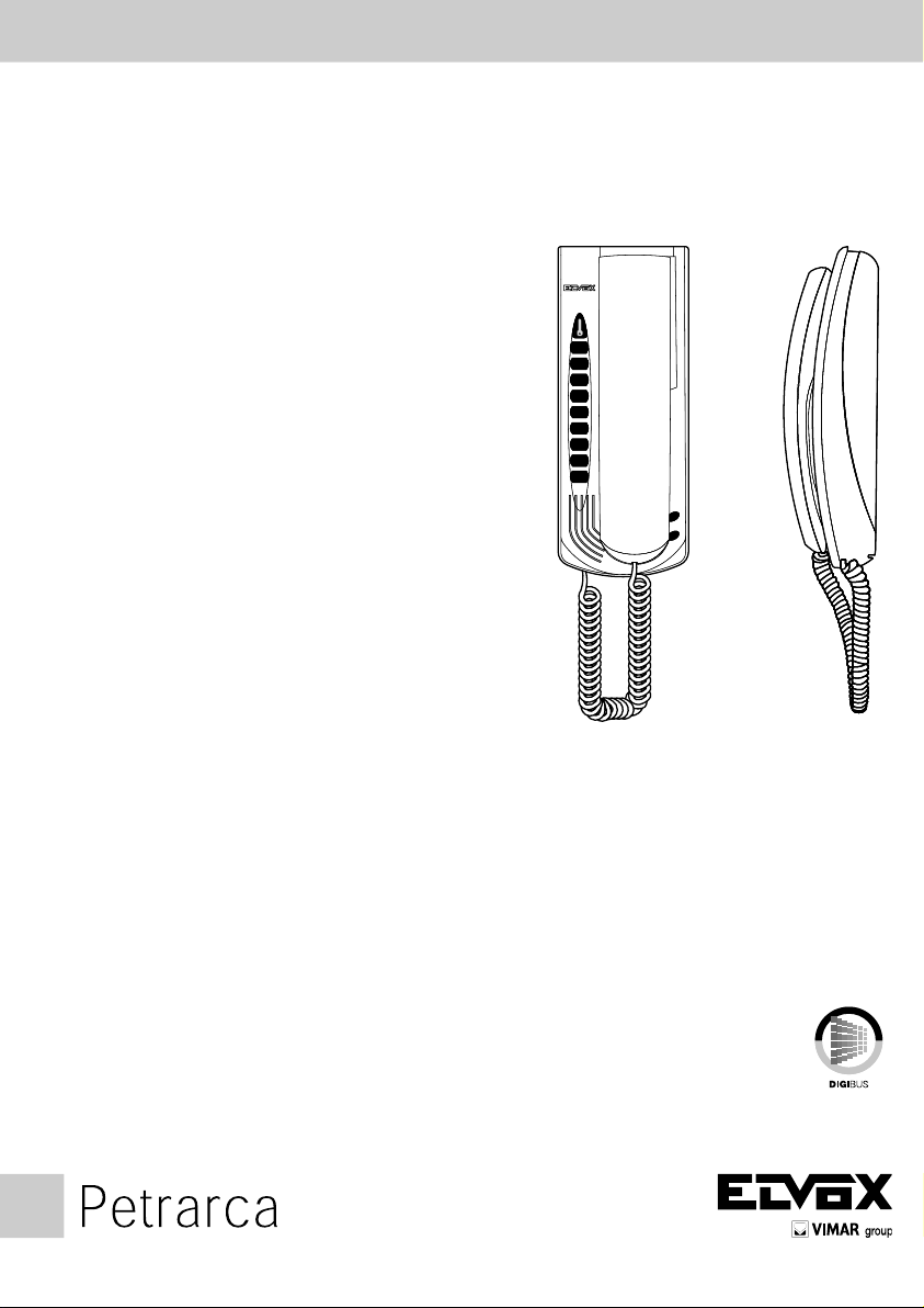
Citofono Petrarca Digibus
Petrarca Digibus interphone
Poste Petrarca Digibus
Haustelefon Petrarca Digibus
Portero automático Petrarca Digibus
Porteiro automático Petrarca Digibus
Page 2

Il manuale istruzioni è scaricabile dal sito www.vimar.com
Descrizione
L’art. 6204 è un citofono della serie DigiBus con codica interna per sistemi di codica a 4 e 8 cifre. Può essere combinato con
i monitor della serie Petrarca (art. 6000 e 6003) per mezzo di staffe o di kit di trasformazione. Il pulsante di serratura è abilitato
solo dopo che il citofono è stato chiamato, quando il citofono è a riposo lo stesso pulsante ha la funzione di chiamata portiere,
con invio del numero di decodica al centralino. Le funzioni supplementari F1, F2, F3, F4, F5, F6, F7, F8, sono utilizzabili tramite
i pulsanti supplementari art. 6C59 (da collegare ai connettori T1, T2, T3) mentre la funzione “utente-assente” è attivabile tramite
l’art. 6153. Inoltre il citofono può essere collegato ad un posto esterno supplementare tipo Art. 930D.
Morsettiera di collegamento
1 Linea digitale per tramissione/ricezione.
3 Linea di fonica e chiamata.
4 Linea di riferimento massa (alimentazione).
5 Linea +13,5Vcc (alimentazione).
6 Linea citofono inserito (và a massa quando il citofono è stato inserito da una chiamata digitale).
12 Linea di fonica supplementare per posto esterno 930D.
11 Linea per chiamata fuori porta.
Connettori
T1 Per funzioni ausiliarie F1 e F2 da collegare ad una coppia di pulsanti art. 6C59.
T2 Per funzioni ausiliarie F3, F4, F5 e F6 da collegare ad una coppia di pulsanti art. 6C59. Il primo pulsante attiva le
T3 Per funzioni ausiliarie F7 e F8 da collegare ad una coppia di pulsanti art. 6C59.
Program. Riservato, da utilizzare solo su indicazione del costruttore.
U.A. Per funzione “utente-assente” da collegare all’art. 6153.
Monit. Per collegamento scheda di interconnessione monitor.
BL, BI Collegamento microtelefono (lo blu e bianco)
C Comune altoparlante di chiamata
A+ Collegamento altoparlante di chiamata per massima potenza
A- Collegamento altoparlante di chiamata per suoneria attenuata
funzioni F3, F4 e F5 in modo ciclico il secondo attiva la funzione F6.
Programmazione e funzionamento
Le operazioni che seguono devono essere effettuate solo dopo la programmazione della targa. Per programmare il numero del
citofono togliere il coperchio, premere il pulsante “PRG” presente sul circuito e successivamente premere e mantenere premuto
il pulsante “LOCK” relativo alla serratura. Se l’operazione è stata eseguita correttamente, il citofono entra in programmazione
accendendo il diodo LED presente sul circuito del citofono. In questo istante si può rilasciare il pulsante “LOCK”(relativo alla
serratura). Se il LED non si accende ripetere l’operazione. Ora col microtelefono del citofono è possibile comunicare con la targa
di scala afnché venga inviato il codice relativo al citofono da programmare. Quando il codice proveniente dalla targa arriva al
citofono, questi lo memorizza e lo mantiene no alla prossima eventuale programmazione, anche durante le fasi di mancanza
della tensione di alimentazione dell’impianto. Il citofono emette il suono di chiamata a conferma dell’avvenuta programmazione.
Riporre il microtelefono del citofono. Nel caso di impianti con scale con più di una entrata, è necessario estrarre il connettore
relativo al montante citofoni delle targhe, lasciandone una sola in funzione per la sola fase di programmazione. L’operazione di
programmazione può essere ripetuta più volte con numeri compresi fra i valori 0000 0001 e 9999 9999.
2
IT
Page 3

The instruction manual is downloadable from the site www.vimar.com
Description
Part No. 6204 is an interphone belonging to the DigiBus series with internal coding for 4 and 8 digit coding systems. It can be
combined with the monitors belonging to the Petrarca series (part No. 6000 and 6003) by means of brackets or transformation
kits. The lock button is enabled only if the interphone has been called. When the interphone is in the rest state, the same button
fulls the function of calling the porter, and sending the decoding number to the switchboard. The supplementary functions F1,
F2, F3, F4, F5, F6, F7 and F8 can be used by means of the supplementary buttons, part No. 6C59, while the “user-absent”
function can be activated by means of part No. 6153. The interphone can also be connected to a supplementary speech unit
such as part No. 930D.
Connection terminal board
1 Digital line for transmission/reception.
3 Voice and call line.
4 Ground reference line (power supply).
5 Line +13.5V DC (power supply).
6 Interphone line ON (goes to ground when the interphone has been switched on by a digital call).
12 Supplementary voice line for 930D speech unit.
11 Line for door call.
Connectors
T1 For auxiliary functions F1 and F2 to be connected to a pair of buttons, part No. 6C59.
T2 For auxiliary functions F3, F4, F5 and F6 to be connected to a pair of buttons, part No. 6C59. The rst button activates
T3 For auxiliary functions F7 and F8 to be connected to a pair of buttons, part No. 6C59.
Program. Reserved, to be used only as instructed by the manufacturer.
U.A. For “user-absent” function, to be connected to part No. 6153.
Monit. For connecting a monitor interconnection card.
BL,BI Handset connection (blue and white wire)
C Common wire for call loudspeaker
A+ Call louspeaker connection for maximum power
A- Call loudspeaker connection for attenuated chime
functions F3, F4 and F5 cyclically; the second activates function F6.
Programming and operation
The following operations must be carried out only after the entrance panel has been programmed. To program the interphone
number, remove the cover, press the PRG button on the circuit board and hold down the “LOCK” button.
If the procedure has been effected correctly, the unit will assume programming mode with led (present on the interphone circuit
board) lighting up, at which point “LOCK” push-button (related to door lock) can be released. .
If the LED does not light up, the sequence must be repeated. The interphone handset will now enable communication with the
stairway panel so that the latter sends back the interphone code. As the code is transmitted from the panel to the phone, it will
be memorized by the unit and remain stored until further programming, even in the event of the panel being disconnected from
the power supply. The entryphone generates a call sound in confirmation of the programming operation. Hook the handset again.
In case of installations with several entries, the connector for the entrance panel interphone riser must be removed, leaving only
one entrance panel in operation for the programming phase.
This operation can be repeated any number of times, using other numbers between 0000 0001 and 9999 9999.
EN
3
Page 4

Télécharger le manuel d’instructions sur le site www.vimar.com
Description
L’art. 6204 est un poste d’appartement de la série DigiBus avec codage interne pour systèmes de codage à 4 et 8 chiffres. Il
peut être combiné avec les moniteurs de la série Petrarca (art. 6000 et 6003) à l’aide de brides ou d’un kit de transformation.
Le bouton de gâche n’est validé qu’après que le poste d’appartement ait été appelé; lorsque le poste est au repos, ce bouton
sert pour l’appel portier, avec envoi du numéro de décodage au standard. Les fonctions supplémentaires F1, F2, F3, F4, F5, F6,
F7, F8 peuvent être utilisées au moyen des boutons supplémentaires art. 6C59, alors que la fonction “usager-absent” peut être
activée grâce à l’art. 6153. En outre, le poste d’appartement peut être relié à un poste externe supplémentaire type art. 930D.
Bornier de connexion
1 Ligne numérique pour émission/réception.
3 Ligne phonique et appel.
4 Ligne de référence masse (alimentation).
5 Ligne +13,5 V cc (alimentation).
6 Ligne poste inséré (se met à la masse lorsque le poste est inséré par un appel numérique).
12 Ligne phonique supplémentaire pour poste externe 930D.
11 Ligne pour appel hors du portail.
Connecteurs
T1 Pour fonctions auxiliaires F1 et F2 à connecter à deux boutons art. 6C59.
T2 Pour fonctions auxiliaires F3, F4, F5 et F6 à connecter à deux boutons art. 6C59. Le premier bouton active les fonc-
T3 Pour fonctions auxiliaires F7 et F8 à connecter à deux boutons art. 6C59.
Program. Réservé, à utiliser exclusivement sur indication du fabricant.
U.A. Pour fonction “usager-absent” à connecter à l’art. 6153.
Monit. Pour branchement carte d’interconnexion moniteur.
BL,BI Raccordement combiné (l bleu et blanc)
C Commun haut-parleur d’appel
A+ Raccordement haut-parleur d’appel pour puissance maximale
A- Raccordement haut-parleur d’appel pour sonnerie attenuée.
tions F3, F4 et F5 en mode cyclique ; le second active la fonction F6.
Programmation et fonctionnement
Les opérations qui suivent ne doivent être effectuées qu’après la programmation de la plaque. Pour programmer le numéro du
poste, retirer le couvercle, presser le bouton “PRG” se trouvant sur le circuit puis appuyer sur le bouton “LOCK” en gardant le
doigt dessus.
Si le procédé a été effectué correctement, le poste d’appartement entre en programmation en allumant la diode LED presente
dans le circuit du poste d’appartement.
A ce même instant, relâcher le bouton-poussoir “LOCK” (relatif à la gâche). Si la diode ne s’allume pas, répéter l’opération.
Maintenant, avec le combiné du poste, communiquer avec la plaque de l’escalier afin que le code relatif au poste programmé
soit envoyé.
Lorsque le code qui provient de la plaque arrive au poste, ce dernier le mémorise et le maintient jusqu’à la programmation suivante, même durant les phases avec absence du courant qui alimente l’installation. Le poste émet le son d’appel pour confirmer
que l’appel a eu lieu. Remettre en place le combiné du poste. En cas d’installations avec des escaliers disposant de plusieurs
entrées, extraire le connecteur relatif au montant/postes des plaques, pour en laisser une seule en service et uniquement pour
la phase de programmation. L’opération de programmation peut être répétée plusieurs fois avec des numéros compris entre les
valeurs 0000 0001 et 9999 9999.
4
FR
Page 5

Die Bedienungsanleitung ist auf der Website www.vimar.com zum Download verfügbar
Beschreibung
Art. 6204 ist ein Gegensprechgerät der Serie DigiBus mit interner Codierung für Codierungssysteme mit 4 und 8 Ziffern. Es kann
mit den Monitoren der Serie Petrarca (Art. 6000 und 6003) mit Hilfe der Montagebügel oder eines Umrüstbausatzes kombiniert
werden. Die Schlosstaste wird nur dann freigegeben, wenn das Gegensprechgerät angerufen wurde; wenn das Gegensprechgerät nicht in Betrieb ist, dient diese Taste als Portierruftaste mit Übersendung der Entschlüsselungszahl an die Zentrale. Die
Zusatzfunktionen F1, F2, F3, F4, F5, F6, F7, F8 können über die Zusatztasten Art. 6C59 verwendet werden, während die
Funktion “Benutzer-abwesend” über den Artikel 6153 aktiviert werden kann. Die Gegensprechanlage kann außerdem an eine
Außenstelle vom Typ Art. 930D angeschlossen werden.
Anschlussklemmenbrett
1 Digitale Linie für Sendung/Empfang.
3 Ton- und Rueitung.
4 Erdungsbezugsleitung (Versorgung).
5 Leitung +13,5 VDC (Versorgung).
6 Linie Gegensprechanlage Ein (wird an Erde angeschlossen, wenn das Gegensprechgerät von einem digitalen Anruf einge-
schaltet wurde).
12 Zusätzliche Tonleitung für Außenstelle 930D.
11 Linie für Türruffunktion
Verbinder
T1 Für Hilfsfunktionen F1 und F2, die an ein Paar Tasten Art. 6C59 anzuschließen sind.
T2 Für Hilfsfunktionen F3, F4, F5 und F6, die an ein Paar Tasten Art. 6C59 anzuschließen sind. Die erste Taste aktiviert
T3 Für Hilfsfunktionen F7 und F8, die an ein Paar Tasten Art. 6C59 anzuschließen sind.
Program. Vorbehalten, darf nur auf Angabe des Herstellers verwendet werden.
U.A. Für die Funktion “Benutzer-abwesend”, für den Anschluss an Art. 6153.
Monit. Für den Anschluss einer Monitor-Zwischenverbindungskarte.
BL,BI Höreranschluß (blauer und weisser Draht)
C Gemeinsamer Draht für Ruautsprecher
A+ Ruautsprecheranschluß für maximum Stromstärke.
A - Ruautsprecheranschluß für abgeschwächte Klingel.
die Funktionen F3, F4 und F5 im zyklischen Modus, die zweite aktiviert dagegen die Funktion F6.
Programmierung und Betrieb
Die folgenden Maßnahmen dürfen erst nach der Programmierung des Klingeltableaus erfolgen. Zur Programmierung der Sprechstellennummer den Deckel abnehmen, die Taste “PRG” am Schaltkreis drücken, anschließend die Türöffnertaste “LOCK” drü-
cken und festhalten.
Wenn der Vorgang vollkommen durchgeführt wurde, wird das Haustelefon programmiert und die bei der Haustelefonkreis diode
LED beleuchtet. Nun kann die “LOCK” Taste (in Bezug auf den Türöffner) gelöst werden. Leuchtet die LED nicht, muß dieser
Vorgang wiederholt werden. Nun kann über den Hörer das Haustelefons mit dem Klingeltableau im Treppenhaus gesprochen
werden, damit der Code der zu programmierenden Sprechstelle gesendet wird. Wenn der Code vom Paneel zur Innenstelle
gesendet wurde, bleibt er bis “zu” einer neuerlichen Programmierung gespeichert. Dies ist auch der Fall, wenn das Klingeltableau
von der Stromversorgung getrennt wird. Die Innenstelle erzeugt einen Rufton zur Bestätigung der Programmierung.
Den Hörer wieder auegen.
Bei Installationen mit mehreren Eingängen darf nur ein Tableau während der Programmierphase angeschlossen sein. Dieser
Vorgang kann mit anderen Nummern zwischen 0000 0001 und 9999 9999 beliebig oft wiederholt werden.
DE
5
Page 6

El manual de instrucciones se puede descargar en la página web www.vimar.com
Descripción
El Art. 6204 es un teléfono de la serie DigiBus con codicación interna para sistemas de codicación de 4 o 8 cifras. Puede ser
acoplado a los monitores de la serie Petrarca (art. 6000 y 6003) por medio de soportes o de kits de transformación. El pulsador de
la cerradura es habilitado sólo después que el teléfono ha sido llamado; cuando el teléfono se encuentra en posición de reposo
el mismo pulsador tiene la función de llamada operador conserjería, con envio del número de decodicación a la central. Las
funciones suplementarias F1, F2, F3, F4, F5, F6, F7 y F8 son utilizables por medio de los pulsadores suplementarios art. 6C59
(para conectar al conector T1, T2 y T3), mientras la función “ usuario ausente “ puede ser activada por el art. 6153. Además, el
teléfono puede ser conectado a un aparato externo suplementario art. 930D.
Regletas de conexiones
1 Línea digital para transmision/recepción.
3 Línea audio o de llamada.
4 Línea de referencia masa (alimentación).
5 Línea +13,5V cc (alimentación).
6 Línea teléfono insertado (va a massa quando el teléfono ha sido isertado por una llamada digital).
12 Línea audio suplementaria para aparato externo 930D.
11 Línea para llamada puerta apartamiento.
Conectores
T1 Para funxiciones auxiliares F1 y F2, para conectar a un par de pulsadores art. 6C59.
T2 Para funciones auxiliares F3, F4, F5 ed F6, para conectar a un par de pulsadores art. 6C59. El primer pulsador activa
T3 Para funzione auxiliares F7 y F8, para conectar a un par de pulsadores art. 6C59.
Program. Reservado, para utilizar sólo cuando el constructor lo requiere.
U.A. Para la función “usuario ausente”, para conectar al art. 6153.
Monit. Para conectar a la cha de interconexión monitor.
BL,BI Conexionado microteléfono (hilo azul e blanco)
C Común altavoz de llamada
A+ Conexionado altavoz de llamada para potencia máxima
A- Conexinado altavoz de llamada para timbre atenuado
las funciones F3, F4 e F5 de modo cíclico; el segundo activa la función F6.
Programación y funcionamiento
Las operaciones que siguen deben ser efectuadas solamente después de la programación de la placa. Para programar el número del interfono quitar la tapa, presionar el pulsador “PRG” presente en el circuito y luego presionar y mantener presionado
el pulsador “LOCK”.
Si el procedimiento ha sido efectuado correctamente, el teléfono entra en programación encendiendo el diodo LED presente
en el circuito del teléfono.
En este instante se puede soltar el pulsador “LOCK”(relativo a la cerradura). Si el diodo no se ilumina, repetir la operación. Ahora
con el microinterfono del interfono es posible comunicar con la placa segundaria y enviar el código relativo al interfono que hay
que programar. Cuando el código proveniente de la placa llega al interfono, éste lo memoriza y lo mantiene memorizado hasta
la próxima eventual programación, también durante las fases de falta de tensión de alimentación en la instalación. El interfono
emite el sonido de llamada para confirmar que la programación ha sido efectuada. Colgar el microinterfono.
Cuando hay instalaciones con escaleras con más de una entrada, extraer el conector relativo al montante interfonos de las
placas, dejando una sola placa en función para la sola fase de programación. La operación de programación puede ser repetida
varias veces con números comprendidos entre los valores 0000 0001 y 9999 9999.
6
ES
Page 7

É possível descarregar o manual de instruções no site www.vimar.com
Descrição
O art. 6204 é um interfone da serie Digibus com codicação interna para sistemas de codicação a 4 ou 8 algarismos. Pode
ser unido aos monitores da série Petrarca (art. 6000 e 6003) por meio de suportes ou de kits de transformação. O botão do
trinco é disponibilizado só depois do interfone ser chamado; quando o interfone ca no estado de reposo o mesmo botão tem
a função de chamada operador da central, com envio do número de decodicação à central. As funcões suplementares F1,
F2, F3, F4, F5, F6, F7 e F8 são utilizáveis através dos botões suplementares art. 6C59 (para ligar ao conetor F1, F2 e T3), em
vez a função “utente ausente” é ativável por medio do botão 6153. Além disso, o interfone pode ser ligado a um posto externo
suplementar art. 930D.
Caixa de ligação
1 Linha digital para transmissão/recepção
3 Linha audio e de chamada
4 Linha de referimento massa (alimentação)
5 Linha 13,5V cc (alimentação).
6 Linha interfone inserido (va a massa quando o interfone foi inserido por uma chamada digital).
12 Linha audio suplementar para posto externo 930D.
11 Linha para chamada no patamar.
Conetores
T1 Para funções auxiliares F1 e F2, para ligar a um par de botões art. 6C59.
T2 Para funções auxiliares F3, F4, F5 E F6, para ligar a um par de botões art. 6C59. o prmeiro botão ativa as funções
T3 Para funções auxiliares F7 e F8, para ligar a um par de botões art. 6C59.
Program. Feservado, para utilizar só quando o construtor o requere.
U.A. Para função “utente-ausente”, para ligar ao Art. 6153.
Monit. para ligação placa de interligação monitor.
BL,BI Ligação punho (o azul e branco)
C Comúm altifalante de chamada
A+ Ligação altifalante de chamada para potência máxima
A- Ligação altifalante de chamada para campainha atenuada
F3, F4 e F5 de modo cíclico; o segundo botão ativa a função F6.
Programação e funcionamento
As operações que se seguem só devem ser efectuadas depois da programação da botoneira. Para programar o número do
telefone retirar a cobertura, premir o botão “PRG” existente no circuito e, a seguir, premir e manter premido o botão “LOCK”.
Se o procedimento foi efetuado corretamente, o telefone entra em programação acendiendo o diodo LED presente no circuito
do telefone.
Neste instante, pode-se libertar o botão “LOCK” (referido ao trinco). Se o LED não se acender, repetir esta operação. Agora,
através do telefone, é possível comunicar com a botoneira do patamar para que sejam enviados os códigos referentes ao
telefone a programar.
Quando o código proveniente da botoneira chega ao telefone, este memoriza-o e mantém-no até à próxima programação,
mesmo durante as fases de falha na tensão de alimentação da instalação. O telefone emite o toque de chamada para conrmar
o sucesso da programação.
Pousar o telefone.
No caso de instalações com mais de uma entrada, é necessário extrair o conector referente à coluna montante dos telefones
das botoneiras, deixando apenas uma em funcionamento para a fase de programação. A operação de programação pode ser
repetida várias vezes com números compreendidos entre os valores 0000 0001 e 9999 9999.
PT
7
Page 8

75
60
220
MONTANTE CITOFONI
INTERPHONE CABLE RISER
MONTANT POSTES
HAUSTELEFONEN-STEIGLEITUNG
MONANTE INTERFONOS
COLUNA MONTANTE DOS TELEFONES.
Rif schema - Ref. diagram - Réf. schéma - Siehe Plan - Ref. esquema - Refª esquema pv4407-1
Citofono
Phone
Poste
Haustelefon
Interfono
Telefono
Art. 6204
8
MONTANTE CITOFONI - INTERPHONE CABLE RISER
MONTANT POSTES - HAUSTELEFONEN-STEIGLEITUNG
MONTANTE INTERFONOS - COLUNA MONTANTE DOS TELEFONES
1435
1
3
4
5
6
12
11
413 5
1
3
4
5
6
12
11
ALL’ALIMENTATORE - TO POWER SUPPLY
A L’ALIMENTATION - ZUM NETZGERÄT
AL ALIMENTADOR - PARA O ALIMENTADOR
ART. 6941
Citofono
Phone
Poste
Haustelefon
Interfono
Telefono
Art. 6204
ITENFRDEESPT
Page 9

MONTANTE MONITOR CON APPARECCHI MUNITI DI DECODIFICA INTERNA DEL SEGNALE DIGITALE. MONITOR
CABLE RISER WITH UNITS EQUIPPED WITH INTERNAL DIGITAL SIGNAL DECODING.
MONTANT MONITEURS AVEC APPAREILS ÉQUIPÉS DU DÉCODAGE INTERNE DU SIGNAL DIGITAL.
MONITOR-STEIGLEITUNG MIT APPARATEN MIT INTERNER DIGITALSIGNAL-DECODIERUNG.
MONTANTE MONITOR CON APARATOS PROVISTOS DE CODIFICACIÓN INTERNA DE LA SEÑAL
DIGITAL.
COLUNA MONTANTE DOS MONITORES COM APARELHOS EQUIPADOS COM DESCODIFICADOR INTERNO DO
SINAL DIGITAL.
Rif schema - Ref. diagram - Réf. schéma - Siehe Plan - Ref. esquema - Refª esquema pv4407-2
Monitor
Moniteur
Art. 6020 +
Art. 6204 +
Art. 6145
Monitor
Moniteur
Art. 6023 +
Art. 6204 +
Art. 6145
Distributore
Distributor
Distributeur
Verteiler
Distribuidor
Art. 5556/004 - 5555
CN1
V4
V3
V2
V1
V
V
-
+
MONTANTE MONITOR - MONITOR CABLE RISER
MONTANT MONITEUR - MONITOR-STEIGLEITUNG
COLUNA MONTANTE DOS MONITORES
-
1345
V
V1
M
V2
V3
+A
+
+D
CH
12
11
75ohm 75ohm
M
-
CN2
MONIT.
1
3
4
5
6
75ohm
75ohm
-
1345
V
ALL’ALIMENTATORE - TO POWER SUPPLY
A L’ALIMENTATION - ZUM NETZGERÄT
AL ALIMENTADOR - PARA O ALIMENTADOR
ART. 6948
Monitor
Moniteur
Art. 6020 +
Art. 6204 +
+
Art. 6145
Monitor
Moniteur
Art. 6023 +
V1
M
V2
M
V3
+A
+
-
+D
CH
CN2
MONIT.
1
3
4
5
6
12
11
+
Art. 6204 +
Art. 6145
CN1
PTESDEFRENIT
9
Page 10

VARIANTE-VERSION-SONDERSCHALTUNG-VARIACIÓN 1
Collegamento pulsante chiamata
fuoriporta su citofoni o monitor mu-
niti di decodica interna.
Collegando nell’impianto il modulo generatore di chiamata Art. 0002/831.06
e un trasformatore Art. M832 azio-
nando il pulsante fuoriporta il citofono
e/o il monitor suona con timbro diffe-
rente da quello ottenuto con la chiamata dalla targa esterna.
N.B.: Il ripetitore di chiamata è utilizzato per la sola chiamata fuoriporta.
Anschluß des Wohnungstür-Klingelknopfes an Haustelefonen oder
Monitoren mit interner Decodierung.
Bei Anschluß des Rufgeneratormoduls
Art. 0002/831.06 und eines Transformators Art. M832 läutet bei Betätigung
der Klingel an der Wohnungstür das
Haustelefon und/oder der Monitor mit
anderem Klang als beim Ruf von der
Außenstelle.
N.B.: Der Rufwiederholer wird nur für
den Ruf von der Wohnungstür benutzt.
Door call button connection for interphones/monitors with internal
decoding.
If you connect call generating module
Art. 0002/831.06 and transformer Art.
M832 to the system, and press the
door push-button, the entry phone and/
or monitor will have a ringing sound
different from the sound obtained by
means of the entrance panel.
Conexionado pulsador llamada
puerta apartamiento en interfonos o
monitores provistos de codificación
interna.
Conectando en la instalación el
módulo generador de llamada Art.
0002/831.06 y un transformador Art.
M832, accionando el pulsador puerta
apartamiento el repetidor de llamada
del interfono y/o monitor suena con
tonalidad diferente de aquella de llamada de la placa externa.
N.B.: El repetidor de llamada viene
utilizado para la sola llamada desde la
puerta apartamiento.
Raccordement poussoir appel hors
porte sur postes ou moniteurs équipés du décodage interne.
Si l’on connecte dans l’installation
le module générateur d’appel Art.
0002/831.06 et un transformateur Art.
M832 et que l’on actionne le poussoir
hors de la porte, le poste et/ou le mo-
niteur sonne avec un timbre qui diffère
de celui que l’on obtient avec l’appel à
partir de la plaque externe.
N.B.: Le répétiteur d’appel est utilisé
pour l’appel hors porte seulement.
Ligação do botão de chamada do
patamar em telefones ou monitores
com descodicador interno.
Ligando, na instalação, o módulo gerador de chamada Art. 0002/831.06 e um
transformador Art. M832, accionando
o botão do patamar, o telefone e/ou o
monitor toca com um timbre diferente
do obtido com a chamada da botoneira
externa.
N.B.: O repetidor de chamada só é
utilizado para a chamada do patamar.
10
ITENFRDEESPT
Page 11

4O
MONTANTE CITOFONI
INTERPHONE CABLE RISER
MONTANT POSTES
HAUSTELEFONEN-STEIGLEITUNG
MONTANTE INTERFONOS
COLUNA MONTANTE DOS TELEFONES
3145
CH
1
3
4
5
6
11
12
A
1345CH
B
Citofono
Phone
Poste
Haustelefon
Interfono
Telefono
Art. 6204
Rete - Mains
Réseau - Netz
Red - Rede
C
A- Art. 6209
Alimentatore
Power supply
Alimentation
Rete - Mains
Réseau - Netz
Red - Rede
PRIPRI
OCP20 CP115 PRI
Netzgerät
Alimentador
Art. 6948 - 6941
1515+I+IV1V1 M1M1V2V212 M2M2
++--S1S155CHCH F1F1SS33F2F2 4
O
A- Pulsante fuori porta
B- Generatore di chiamata Art. 0002/831.06
C- Trasformatore Art. M832
A- Outdoor push-button
B- Call generator Art. 0002/831.06
C- Transformer Art. M832
A- Poussoir à la porte de l’appartement
B- Générateur d’appel Art. 0002/831.06
C- Transformateur Art. M832
PTESDEFRENIT
A- Wohnungstür-Klingelknopf
B- Rufgenerator Art. 0002/831.06
C- Transformator Art. M832
A- Botão do patamar
B- Gerador de chamada Art. 0002/831.06
C- Transformador Art. M832
A- Pulsador puerta apartamiento
B - Generador de llamada Art. 0002/831.06
C - Transformador Art. M832
11
Page 12

VARIANTE-VERSION - SONDERSCHALTUNG-VARIACIÓN 2
Collegamento funzioni ausiliarie F1
- F2 in impianti videocitofonici mu-
niti di decodica interna.
È possibile l’attivazione di due funzioni
ausiliarie (F1-F2) comandata dai citofoni collegando due relè Art. 0170/001
come da schema (morsetti R1-4 e
R2-4 dell’alimentatore).
N.B.: Il citofono Art. 6204 richiede l’Art.
6C59 per utilizzare le funzioni F1 e F2.
L’Art. 6C59 permette il collegamento
di pulsanti esterni in parallelo a quelli
forniti con l’accessorio.
Anschluß der Zusatzfunktion F2 an
Video-Türsprechanlagen mit interner Decodierung.
Es ist möglich, eine über den Haustelefon gesteurte Zusatzfunktion
(F1-F2) zu aktivieren, indem 2 Relais
Art. 0170/001 gemäß Schema angeschlossen wird (Klemmen R1-4, R2-4
des Netzgeräts).
ACHTUNG: Das Haustelefon Art.
6204 vordert den Art. 6C59 um die
Funktionen F1 und F2 zu nutzen. Art.
6C59 ermöglicht den Anschluss von
externen Tasten parallel geschaltet an
denen, die mit dem Zubehör mitgelie-
fert sind.
Connecting additional function
F1-F2 to video door entry systems
with internal decoding.
An additional phone controlled functions (F1-F2) can be activated by connecting 2 relais Art. 0170/001 as per
diagram (terminals R1-4, R2-4 of the
power supply).
ATTENTION: Interphone type 6204
requires type 6C59 for the F1 and
F2 functions. Art. 6C59 allows the
connection of external push-buttons
connected in parallel to those supplied
with the accessory.
Conexionado función auxiliares
F1 - F2 en instalaciones con vídeo
portero provistos de codificación
interna.
Es posible la activación de una función
auxiliar (F1, F2) mandada por los interfones conectando 2 relé Art. 0170/001
como de esquema (bornes R1-4, R2-4
del alimentador).
ATENCIÓN: Para utilizar las funciones
F1 y F2 el interfono Art. 6204 requiere
el Art. 6C59. El Art. 6C59 permite el
conexionado de los pulsadores en pa-
ralelo a aquellos suministrados con el
accesorio.
Raccordement des fonctions auxiliaires F1 dans des installations
portiers-vidéo équipés du décodage
interne.
On peut activer une fonction auxiliaire
(F1) commandée par les postes en
reliant un relais Art. 0170/001 selon
le schéma (bornes R1-4 de l’alimen-
tation).
ATTENTION: Le poste d’appartement
Art. 6204 exige l’Art. 6C59 pour utiliser les fonctions F1 et F2. L’Art. 6C59
permet le raccordement des boutons-poussoirs externes en parallèle à
ceux fournis avec l’accessoire.
Ligação das funções auxiliares F1
- F2 em instalações vídeo-porteiros
com descodicador interno.
É possível a activação de uma função auxiliar (F1, F2) comandada dos
telefonos ligando 2 relé Art. 0170/001
como se mostra no esquema (bornes
R1-4, R2-4 do alimentador).
ATENÇÃO: Para utilizar as fuções F1
e F2 o interfone Art. 6204 requer o Art.
6C59. O Art. 6C59 permite a ligação
dos botões externos em paralelo àqueles fornecidos com o acessório.
12
ITENFRDEESPT
Page 13

F1 F2
Citofono
Phone
Poste
Haustelefon
Interfono
Telefono
Art. 6204 +
Art. 6C59
Citofono
Phone
Poste
Haustelefon
Interfono
Telefono
Art. 6204 +
Art. 6C59
MONTANTE CITOFONI
INTERPHONE CABLE RISER
MONTANT POSTES
HAUSTELEFONEN-STEIGLEITUNG
MONTANTE INTERFONOS
COLUNA MONTANTE DOS TELEFONES
1 3 4 - 5 +
1
3
A
4
5
T3 6
11
T2
12
T1
B
A
T3 6
T2
T1
C
C
T1
F1
T2
F2
1
3
4
5
11
12
C
T1
T2
D
V 1 4 3 5 - +
F3, F4, F5
Rete-Mains
Réseau-Netz
Red-Rede
1
3
A
4
5
T3 6
11
T2
12
T1
C
T1
B
T2
F6
1
3
A
4
5
6
T3
11
T2
T1
12
C
T1
F7
F8
B
T2
PRI PRI
Alimentatore-Power supply
Alimentation-Netzgerät
Alimentador-Art. 6948 - 6941
V2 V2 M2 M2 V1 V1 M1 M1 +I +I CH CH F1 F1 S S F2 F2 5 5 3 3 4 4 + + - - 15 15 O O
Citofono
Phone
Poste
Haustelefon
Interfono
Telefono
Art. 6204 +
Art. 6C59
Citofono
Phone
Poste
Haustelefon
Interfono
Telefono
Art. 6204 +
Art. 6C59
R1
4
R2
4
Relè
Relais
Relay
Art. 0170/001
2 1 3 4 5 S1
Relè
Relais
Relay
Art. 0170/001
3 1 2 5 4
A- Art. 6204
B- Art. 6C59
C- Art. 6C59
D- Pulsanti esterni
External push-buttons
Boutons-poussoirs externes
Externtasten
Pulsadores externos
Botões externos
F1
F2
Alla targa o al centralino
To entrance panel or to porter’s switchboard
Vers la plaque de rue ou vers le standard conciergerie
zum Klingeltableau oder zur Zentrale
A la placa o a la central consergería
Para a botoneira ou para a central
PTESDEFRENIT
13
Page 14

• Installazione del citofono • Installation instructions • Conseils pour l’installation
• Installationshinweise • Consejos para la instalación • Conselhos para a instalação
• Aprire il citofono, separare il coperchio dal fondo facendo forza nel lato inferiore del coperchio.
• Open the interphone, split the cover from the bottom making pressure on the lower side of the cover.
• Ouvrir le poste d’appartement, séparer le couvercle du fond en faisant force du côté inférieur du couvercle.
• Das Haustelefon öffnen, den Deckel vom Boden entfernen durch Drücken auf die Unterseite des Deckels.
• Abrir el teléfono, separar la tapa del fondo apretando en el lado inferior de la tapa.
• Abrir o telefone, afastar a tampa do fundo fazendo força no lado inferior da tampa.
• Aggiunta pulsante singolo dell’art. 6152 (confezione da 8 pezzi).
• Additional single push-button type 6152 (available in boxes of 8 pcs).
• Touche supplémentaire Art. 6152 (conditionnement de 8 pièces).
• Zusätzliche Einzeltaste Art. 6152 (Verpackungseinheit mit 8 Stück).
• Pulsador suplementario simple Art. 6152 (embalaje de 8 piezas).
• Botão suplementar art. 6152 (embalagem com 8 peças).
• Dividere i tasti in corrispondenza del pulsante.
• Split the keys corresponding to push-button.
• Diviser les touches relatives au bouton-poussoir.
• Die dem Knopf entsprechedeN Tasten trennen.
• Dividir las teclas en correspondencia de los pulsadores.
• Separar as teclas referentes ao botão.
14
ITENFRDEESPT
Page 15

• Installazione da esterno parete o ad una scatola. Applicabile a muro con
tasselli oppure ad una scatola da incasso 3 moduli (Vimar V71303, V71703).
• Surface-wall mount or box installation. Can be tted to the wall with plugs or
a 3 modules (Vimar V71303, V71703).
• Installation en saillie ou en boîtier. Mural avec chevilles ou en boîtier d’enca
strement 3 modules (Vimar V71303, V71703).
• Aufputzmontage oder Installation in Gehäuse. Wandbefestigung mit Dübeln
oder in rechteckigen UP-Gehäusen 3 Module (Vimar V71303, V71703).
• Montaje de supercie o en caja. Que se monta en la pared con tacos o bien
en una caja de empotrar 3 módulos (Vimar V71303, V71703).
• Instalação tipo montagem saliente ou numa caixa. Aplicável na parede com
buchas ou numa caixa de embeber 3 módulos (Vimar V71303, V71703).
-
Dima di foratura della parete per installazione con tasselli - Wall drilling template for installation with wall plugs - Gabarit de perçage de la cloison pour installation avec chevilles.
Bohrschablone der Wand für die Installation mit Dübeln - Plantilla para taladrar la pared para el montaje con tacos - Molde de perfuração da parede para instalação com buchas.
Οδηγός διάτρησης του τοίχου για εγκατάσταση με ούπα
Ø 5m m
Ø 5 mm
Ø 5mm
Ø 5 mm
PTESDEFRENIT
15
Page 16

REGOLE DI INSTALLAZIONE.
L’installazione deve essere effettuata
con l’osservanza delle disposizioni re
golanti l’installazione del materiale elettrico in vigore nel Paese dove i prodotti
sono installati.
CONFORMITÀ NORMATIVA.
Direttiva EMC
Norme EN 61000-6-1 e EN 61000-6-3.
INFORMAZIONE AGLI UTENTI
AI SENSI DELLA DIRETTIVA
2012/19/UE (RAEE)
Al ne di evitare danni all’ambien
te e alla salute umana oltre che di incorrere in sanzioni amministrative, l’apparecchiatura che riporta questo simbolo
dovrà essere smaltita separatamente
dai riuti urbani ovvero riconsegnata al
distributore all’atto dell’acquisto di una
nuova. La raccolta dell’apparecchiatura
contrassegnata con il simbolo del bidone barrato dovrà avvenire in conformità
alle istruzioni emanate dagli enti territo
rialmente preposti allo smaltimento dei
riuti. Per maggiori informazioni contat
tare il numero verde 800-862307.
INSTALLATION RULES.
Installation should be carried out ob
-
serving current installation regulations
for electrical systems in the Country
where the products are installed.
CONFORMITY.
EMC directive
Standards EN 61000-6-1 and EN
61000-6-3.
INFORMATION FOR USERS
UNDER DIRECTIVE 2012/19/
-
-
-
UE (WEEE)
In order to avoid damage to the
environment and human health as well
as any administrative sanctions, any ap
pliance marked with this symbol must be
disposed of separately from municipal
waste, that is it must be reconsigned to
the dealer upon purchase of a new one.
Appliances marked with the crossed out
wheelie bin symbol must be collected in
accordance with the instructions issued
by the local authorities responsible for
waste disposal.
RÈGLES D’INSTALLATION.
L’installation doit être effectuée dans
le respect des dispositions régulant
l’installation du matériel électrique en
vigueur dans le Pays d’installation des
produits.
CONFORMITÉ AUX NORMES.
Directive EMC
Normes EN 61000-6-1 et EN 61000-6-3.
COMMUNICATION AUX UTILI
SATEURS CONFORMÉMENT
À LA DIRECTIVE 2012/19/UE
(DEEE)
Pour protéger l’environnement et la santé des personnes et éviter toute sanc-
-
tion administrative, l’appareil portant ce
symbole ne devra pas être éliminé avec
les ordures ménagères mais devra être
coné au distributeur lors de l’achat d’un
nouveau modèle. La récolte de l’appareil portant le symbole de la poubelle
barrée devra avoir lieu conformément
aux instructions divulguées par les organisms régionaux préposés à l’élimination des déchets.
-
INSTALLATIONSVORSCHRIFTEN.
Die Installation hat gemäß den im jewei
ligen Verwendungsland der Produkte
geltenden Vorschriften zur Installation
elektrischer Ausrüstungen zu erfolgen.
NORMKONFORMITÄT.
EMC-Richtlinie
Normen DIN EN 61000-6-1 und EN
61000-6-3.
VERBRAUCHERINFORMA
TION GEMÄSS RICHTLINIE
2012/19/UE (WEEE)
Zum Schutz von Umwelt und
Gesundheit, sowie um Bußgelder zu
vermeiden, muss das Gerät mit diesem Symbol getrennt vom Hausmüll
entsorgt oder bei Kauf eines Neugeräts
dem Händler zurückgegeben werden.
Die mit dem Symbol der durchgestrichenen Mülltonne gekennzeichneten
Geräte müssen gemäß den Vorschriften
der örtlichen Behörden, die für die Müllentsorgung zuständig sind, gesammelt
warden.
PTESDEFRENIT
NORMAS DE INSTALACIÓN.
El aparato se ha de instalar en conformi
-
dad con las disposiciones sobre material eléctrico vigentes en el País.
CONFORMIDAD NORMATIVA.
Directiva EMC
Normas EN 61000-6-1 y EN 61000-6-3.
INFORMACIÓN A LOS USUA
-
RIOS DE CONFORMIDAD CON
LA DIRECTIVA 2012/19/UE
(RAEE)
Para evitar perjudicar el medio ambiente y la salud de las personas, así como
posibles sanciones administrativas, el
aparato marcado con este símbolo no
deberá eliminarse junto con los residuos
urbanos y podrá entregarse en la tien-
da al comprar uno nuevo. La recogida
del aparato marcado con el símbolo del
contendedor de basura tachado deberá
realizarse de conformidad con las instrucciones emitidas por las entidades
encargadas de la eliminación de los re-
siduos a nivel local.
REGRAS DE INSTALAÇÃO
A instalacao deve ser efectuada de
-
acordo com as disposicoes que regu
lam a instalacao de material electrico,
vigentes no Pais em que os produtos
sao instalados.
CUMPRIMENTO DE REGULAMENTA
ÇÃO
Directiva EMC
-
Normas EN 61000-6-1 e EN 61000-6-3.
INFORMAÇÃO AOS UTILIZA
DORES NOS TERMOS DA DIRECTIVA 2012/19/UE (REEE)
Para evitar danos ao meio am-
biente e à saúde humana, e evitar incorrer em sanções administrativas, o equipamento que apresenta este símbolo
deverá ser eliminado separatamente
dos resíduos urbanos ou entregue ao
distribuidor aquando da aquisição de
um novo. A recolha do equipamento
assinalado com o símbolo do contentor
de lixo barrado com uma cruz deverá
ser feita de acordo com as instruções
fornecidas pelas entidades territorialmente previstas para a eliminação de
resíduos.
-
-
-
Vimar SpA: Viale Vicenza, 14
36063 Marostica VI - Italy
Tel. +39 0424 488 600 - Fax (Italia) 0424 488 188
Fax (Export) 0424 488 709
www.vimar.com
49400867A0 00 16 05
VIMAR - Marostica - Italy
 Loading...