

Vimar Elvox Giotto Series, Elvox Giotto 6329/CD, Elvox Giotto 6329/C, Elvox Giotto 6329 Installer's Manual
Page 1
Manuale installatore - Installer guide
Manuel installateur - Technisches Handbuch
Instrucciones instalador - Manual do instalador
Giotto
6329, 6329/C, 6329/CD*
Videocitofono Giotto b/n Due Fili / Videocitofono Giotto colori Due Fili
B/W Giotto Due Fili monitor / Colour Giotto Due Fili monitor
Portier-vidéo Giotto b/n Due Fili / Portier-vidéo Giotto couleurs Due Fili
S/W-Videohaustelefon Giotto DueFili / Farb-Videohaustelefon Giotto DueFili
Videoportero Giotto b/n Due Fili / Videoportero Giotto colores Due Fili
Video porteiro Giotto b/p Due Fili / Video porteiro Giotto cores b/p Due Fili
**
Page 2
6329, 6329/C, 6329/CD
Il manuale istruzioni è scaricabile dal sito www.vimar.com
DESCRIZIONE
Gli art. 6329, 6329/C e 6329/CD sono videocitofoni della serie
Giotto rispettivamente con schermo in B/N (6329) e colori
(6329/C, 6329/CD) per impianti videocitofonici Due Fili Plus.
È fornito di serie di 3 pulsanti, uno per l’apertura della serratura, uno per l’autoaccensione del videocitofono nell’impianto
anche quando non è stato chiamato ed uno per servizio luce
scale. Fornito di regolazione del volume di chiamata per 3 livelli e l’esclusione della chiamata. Le segnalazioni luminose di:
chiamata esclusa, chiamate inevase senza risposta, servizi non
disponibili e porta/cancello aperto, sono segnalate tramite i due
LED (rosso e verde) presenti nel videocitofono.
L’installazione del videocitofono può avvenire in versione da
esterno parete, con la staffa (R684) fornita con il videocitofono,
o in versione da tavolo con l’ausilio dei kit di trasformazione
art. 661A o 661F.
* L’Art. 6329/CD è predisposto per l’utilizzo con gli apparecchi
acustici delle persone audiolese. Per attivarlo, selezionare la
posizione “T” dell’apparecchio acustico.
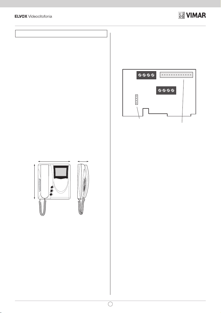
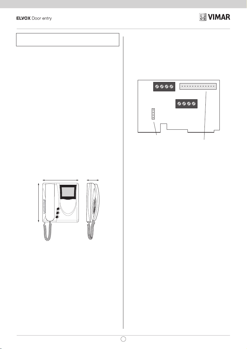
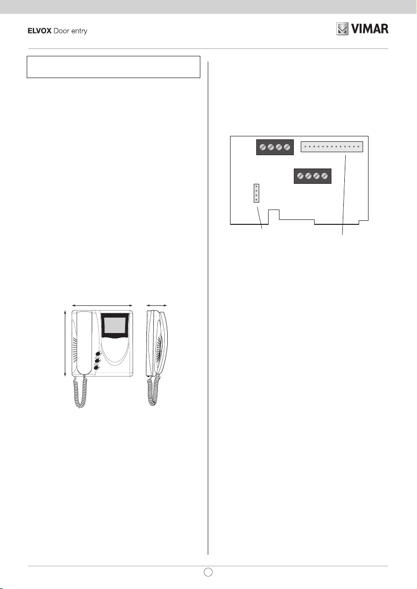
Morsettiera di collegamento e connettori
3, 4) Collegamento suoneria supplementare.
1, 2) Linea BUS.
12 +, 13 - ) Alimentazione supplementare per monitor con ali
mentatore art. 6923.
V3, M) Collegamento per pulsante di chiamata fuoriporta.
CN1) Collegamento per videocitofono.
Fig. 1
ELVOX
CS2350
271103
Stabilizzazione
segnale video
4 3 2 1
A S+BUS
C
B
CN2
A
12 13 V3 M
+ -
EXT. 24V
F.P.
R684
CN1
Per monitor
-
204 mm
71 mm
Caratteristiche tecniche videocitofono
- Videocitofono da esterno parete in ABS
- Piastra di aggancio e tasselli per il fissaggio a parete o scatola a 3 moduli.
- TFT LCD 3,5”
220 mm
- Circuito elettronico su schede intercambiabili.
- Segnale video standard CCIR 625 linee 50 quadri per 6329,
PAL per 6329/C, 6329/CD.
- Banda passante video 4 MHz
- Temperatura di funzionamento da 0° a +40° C.
- Suoneria elettronica.
- Ingresso per chiamata fuori porta con suoneria distinta dalla
chiamata da targa.
- Uscita per suoneria supplementare Art. 860A.
- Alimentazione data dal bus.
- Ingresso per alimentazione supplementare (Art. 6923) nel
caso in cui l’impianto preveda l’accensione di più di due monitor contemporaneamente.
2
IT
Page 3
6329, 6329/C, 6329/CD
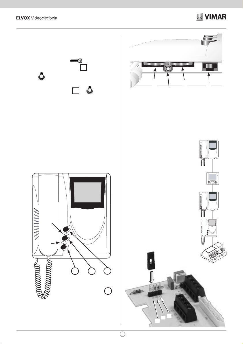
Controlli e regolazioni (Fig. 3 - 4)
A - Regolazione volume ed esclusione suoneria.
B - Regolazione luminosità.
C - Regolazione contrasto per 6329, e colore per 6329/C, 6329/
CD.
D - Pulsante comando serratura
E - Pulsante autoaccensione impianto
F - Pulsante
tore art. .
Premendo assieme i pulsanti
servizio ausiliario, 2° relè del 1° attuatore art. 69RH.
G - Pulsante RESET per programmazioni videocitofono.
H - LED suoneria esclusa. Si accende di luce fissa quando la
suoneria è stata esclusa tramite il cursore “A” e lampeggia
quando sono state rifiutate delle chiamate (led rosso).
I - LED porta aperta. Negli impianti in cui tale funzione è stata
utilizzata, il LED rimane acceso di luce fissa quando la
porta/cancello è aperta (led verde).
Fig. 3
per servizio ausiliario, 1° relè del 1° attua-
.
.
ed , si attiva un 2°
H
I
Fig. 4
C
B
G
STABILIZZAZIONE SEGNALE
VIDEO
Sulla scheda di interconnessione del
videocitofono (nella piastra di fissaggio)
è presente un connettore (A-B-C) ed un
ponticello per la stabilizzazione del segnale video (Fig. 9). Questo ponticello
deve essere utilizzato negli impianti dove
sono presenti più apparecchi (citofoni/videocitofoni) collegati in serie (Fig. 8).
Spostare il ponticello solo dell’ultimo apparecchio nella posizione “B” e mantenere i ponticelli degli altri nella posizione
iniziale “A”.
Per altre configurazioni di collegamento
vedere: la “TABELLA TERMINAZIONE
PER IMPIANTI DUE FILI ELVOX “ riportata nella sezione schemi di collegamento.
Fig. 9
A
B
A
A
A
E
F
D
P2
P0
P1
P1 + P2 (Assieme) = P3
Fig. 8
C
B
A
IT
3
Page 4
6329, 6329/C, 6329/CD
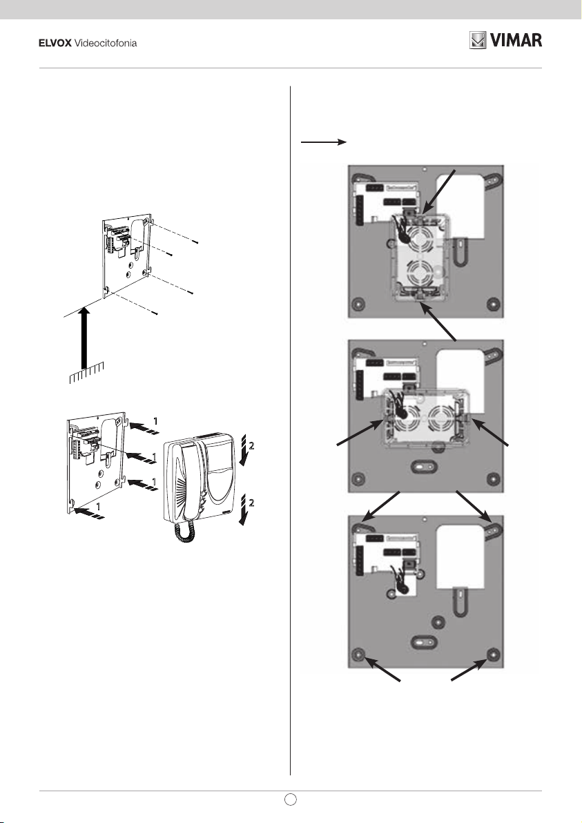
INSTALLAZIONE
- Installare il monitor lontano da fonti lu mi no se e di ca-
lore.
- Fissare la piastra d’ag gan cio monitor alla parete a circa 1,40
m dal bor do inferiore al pa vi men to (Fig. 5).
- Eseguire i collegamenti sulla morsettiera del monitor.
- Inserire il monitor seguendo il senso delle frecce 1 e 2 (Fig.
6).
Fig. 5
1,40
L’installazione della piastra può avvenire utilizzando una scatola da incasso da 3 moduli (orizzontale o verticale) o con tasselli a pressione.
Punti di fissaggio
Fig. 7
1
Fig. 6
2
1
1
1
4
2
IT
Page 5
6329, 6329/C, 6329/CD
PROGRAMMAZIONE
Le programmazioni del videocitofono sono di tre tipi: assegnazione codice identificativo o codice di chiamata (indispensabile),
assegnazione codice identificativo secondario (per videocitofoni
associati ad un videocitofono di “capogruppo”), programmazione pulsanti per servizi ausiliari e chiamate intercomunicanti
(dove necessario).
Le programmazioni devono essere effettuate con l’impianto acceso, senza comunicazioni attive e solamente dopo aver collegato i citofoni/videocitofoni all’impianto e programmato le targhe.
N.B: tutte le fasi di programmazione o cancellazione delle
stesse, devono essere effettuate con il microtelefono del
videocitofono sganciato.
Programmazione codice identificativo
Il codice identificativo va programmato per mezzo di una targa
principale (MASTER), presente nell’impianto e già configurata.
Il videocitofono viene fornito senza codice identificativo associato. Per verificare ciò premere il pulsante serratura e il videocitofono emetterà un triplo “Bip”.
Attenzione: durante la programmazione del codice di identificazione del videocitofono si hanno a disposizione 30
secondi dal momento in cui si entra in programmazione
nel videocitofono al momento in cui si preme il pulsante di
chiamata sulla targa o si invia il codice.
Fase di programmazione:
1) Sganciare il microtelefono
2) Premere e mantenere premuto il pulsante RESET “G”
presente sotto il videocitofono (vedi Fig. 4).
3) Premere e mantenere premuto il pulsante serratura “D”
assieme al pulsante RESET “G”.
4) Rilasciare il pulsante RESET “G”, continuando a tenere
premuto il pulsante serratura “D”.
5) Dopo 2 secondi il videocitofono emette un tono acuto, si
accende il monitor e viene messo in comunicazione con
la targa.
6) Rilasciare il pulsante serratura “D”.
7) Nelle targhe a pulsanti premere il pulsante di chiamata
corrispondente al videocitofono, invece nelle targhe alfanumeriche comporre il codice di chiamata e premere il
pulsante “
8) Se nell’impianto esiste già un videocitofono con lo stesso
codice identificativo associato, la targa emette un segnale
sonoro basso ed è necessario ripetere l’operazione dal
punto 2.
9) In caso contrario il codice viene associato al videocitofono, la comunicazione viene terminata e il monitor si
spegne.
Programmazione codice identificativo secondario
La programmazione del codice identificativo secondario è richiesta solamente quando si vuole far suonare contemporaneamente più di un videocitofono con lo stesso pulsante o codice
di chiamata. I videocitofoni che devono suonare contemporaneamente vengono associati ad uno stesso gruppo. Il videocitofono di “capogruppo” viene programmato per primo attraverso la
”.
precedente procedura “programmazione codice identificativo”,
invece i videocitofoni aggiuntivi del gruppo vengono program
mati con il codice identificativo secondario (vedi tabella riportata
nella sezione schemi di collegamto).
Il numero di videocitofoni che si possono associare ad uno
stesso gruppo, senza l’ausilio del programmatore art. 950C,
sono 3 più un capogruppo.
Nel caso si voglia far accendere contemporaneamente più
di due videocitofoni, è necessario aggiungere un alimentatore supplementare art. 6923 per ogni eventuale monitor
aggiuntivo.
In alternativa utilizzando il programmatore art. 950C o SaveProg è possibile programmare l’attivazione della suoneria
di tutti i videocitofoni e l’accensione del monitor del solo
capogruppo. Prima di rispondere rispondere da un videocitofono secondario si può accendere il relativo monitor tra-
mite il tasto di autoaccensione.
Fase di programmazione:
1) Sganciare il microtelefono
Per conoscere il numero assegnato fare riferimento alla tabella
Programmazione pulsanti
Il videocitofono viene fornito con tre pulsanti per le funzioni
di serratura, autoaccensione e per il servizio ausiliario “luce
scale”, il quale attiva il 1° relè del 1° attuatore (art. 69RH), se
collegato all’impianto.
Per cambiare il tipo di funzionamento del pulsante autoaccensione e servizio ausiliario “luce scale” è necessario utilizzare il
programmatore art. 950C o SaveProg, ad eccezione della funzione chiamata intercomunicante per luce scale.
Durante la programmazione dei pulsanti il regolatore di volume suoneria non deve essere in posizione di suoneria
esclusa.
Programmazione pulsante per chiamata intercomunicante
-
2) Premere e mantenere premuto il pulsante RESET “G”
presente sotto il videocitofono (vedi Fig 4).
3) Premere e mantenere premuti il pulsante serratura “D” e
il pulsante di autoaccensione
sante RESET “G”.
4) Rilasciare il pulsante RESET “G”, continuando a tenere
premuti gli altri 2 pulsanti (D e E).
5) Dopo 2 secondi il videocitofono emette un tono acuto, si
accende il monitor e viene messo in comunicazione con
la targa.
6) Rilasciare il pulsante serratura “D” e il pulsante di autoaccensione “E”.
7) Nelle targhe a pulsanti premere il pulsante di chiamata
corrispondente al videocitofono di “capogruppo”, invece
nelle targhe alfanumeriche comporre lo stesso codice di
chiamata del videocitofono di “capogruppo” e premere il
pulsante “
8) Associato l’identificativo secondario al videocitofono, la
comunicazione viene terminata e il monitor si spegne.
riportata nella sezione schemi di collegamto.
”.
“E”, assieme al pul-
IT
5
Page 6

6329, 6329/C, 6329/CD
“ ” (P2).
Fase di programmazione:
1) Sganciare il microtelefono del citofono/videocitofono
da chiamare, se della serie 8870, Giotto,Petrarca. Per
tutte le versioni della serie 6600 (senza microtelefono), premere e tenere premuto il tasto parla/ascolta
presente sotto il videocitofono (vedi Fig. 4).
3) Premere e mantenere premuto il pulsante interessato da
riprogrammare assieme al pulsante RESET “G”.
4) Rilasciare il pulsante RESET “G”, continuando a tenere
premuto l’altro pulsante.
5) Dopo 2 secondi il citofono emette un tono acuto.
6) Rilasciare il pulsante da riportare a default e ripremerlo.
.
2) Premere e mantenere premuto il pulsante RESET “G”
presente sotto il videocitofono (vedi Fig. 4) da cui dovrò
inviare la chiamata.
3) Premere e mantenere premuto il pulsante per eseguire la
chiamata intercomunicante assieme al pulsante RESET
“G”.
4) Rilasciare il pulsante RESET “G”, continuando a tenere
premuto il pulsante di chiamata.
5) Dopo 2 secondi il videocitofono emette un tono acuto,
mentre l’altro citofono/videocitofono emette una scala tritonale ascendente.
6) Rilasciare il pulsante relativo alla chiamata intercomunicante.
7) Premere nel citofono/videocitofono chiamato (quello con il
suono tritonale), uno dei pulsanti programmati come serratura, F1, F2 o attuatore.
8) Un tono acuto conferma la fine della procedura.
Ripetere la stessa procedura anche per gli altri citofoni/videocitofoni ed eventuali pulsanti di chiamata intercomunicante
Programmazione pulsante autoaccensione verso
targa specifica.
Con questa procedura è possibile attivare solo il pulsante
. Il pulsante di default attiva l’autoaccensione della targa
principale (master) in alternativa può essere programmato solo
tramite programmatore 950C o SaveProg) per attivare l’autoaccensione di altre targhe.
Fase di programmazione:
1) Alzare il microtelefono
2) Premere e mantenere premuto il pulsante “F”
eseguire l’autoaccensione assieme al pulsante RESET
“G”.
3) Rilasciare il pulsante RESET “G”, continuando a tenere
premuto il pulsante “F”.
5) Dopo 2 secondi il videocitofono emette un tono acuto.
5) Rilasciare il pulsante “F”.
6) Nelle targhe a pulsanti premere il pulsante di chiamata
corrispondente al videocitofono, invece nelle targhe alfanumeriche comporre il codice di chiamata e premere il
pulsante “
7) Un tono acuto conferma la fine della procedura.
”.
per
Riprogrammazione valore di default dei pulsanti.
Fase di programmazione:
1) Sganciare il microtelefono
2) Premere e mantenere premuto il pulsante RESET “G”
6
IT
Cancellazione totale delle programmazioni.
Fase di programmazione:
Questa procedura è consigliata quando si vuole cambiare
l’ID di un citofono/videocitofono precedentemente programmato e non si vuole mantenere la programmazione di
funzionamento dell’apparecchio.
1) Sganciare il microtelefono.
2) Premere e mantenere premuto il pulsante RESET “G” pre
sente sotto il videocitofono (vedi Fig. 4)
3) Premere e mantenere premuto il pulsante di autoaccen-
sione “E” assieme al pulsante RESET “G”.
4) Rilasciare il pulsante RESET “G”, continuando a tenere pre
muto il pulsante autoaccensione “E”.
5) Dopo 2 secondi il videocitofono emette, per 2 secondi, un
tono lungo.
6) Rilasciare il pulsante autoaccensione “E”.
7) Durante il tono lungo, premere il pulsante serratura “D”.
Se la procedura di cancellazione è andata a buon fine, premendo nuovamente la lamella della serratura il citofono emetterà un triplo “Bip”.
-
-
FUNZIONAMENTO
Le chiamate da targa esterna, intercomunicante e fuoriporta
sono differenziate tra loro da toni diversi.
Chiamata da targa.
Le chiamate da targa non seguono la durata della pressione
del pulsante di chiamata ma vengono generate internamente
dal videocitofono. Il periodo di chiamata è 1 s di suono e 2 s
di pausa ripetuto per 2 volte (valore di default impostato nella
targa). Per rispondere, sollevare il microtelefono. Se il microtelefono è già sollevato durante la chiamata riagganciare e risollevarlo. Il tempo di risposta alla chiamata (30 s) e il tempo di
conversazione (2 minuti di default) sono impostati nei parametri
della targa. Scaduto il tempo di conversazione, si può continuare, senza riagganciare il microtelefono, se viene eseguita di
nuovo la chiamata entro 10 s dalla stessa targa.
Chiamata intercomunicante.
Sollevare il microtelefono del videocitofono, premere il pulsante
intercomunicante, se programmato, relativo al citofono/videocitofono da chiamare. Nel microtelefono del videocitofono chiamante si udrà un tono di chiamata (se la chiamata è possibile)
o tono di occupato (se la chiamata non è possibile). Nel videocitofono chiamato la suoneria inizierà a suonare ciclicamente
con un ritmo di 1 s di suono e 4 s di pausa. La durata massima
della chiamata sarà di 30 s (6 cicli). Per rispondere alla chiamata
Page 7
6329, 6329/C, 6329/CD
è sufficiente sollevare il microtelefono; la durata massima della
conversazione è di 5 minuti. Scaduto il tempo di conversazione
si può continuare la conversazione, senza riagganciare il microtelefono, se viene eseguita di nuovo la chiamata entro 10
s. Un’eventuale chiamata da targa ha priorità su quella intercomunicante.
Regole di installazione
L’installazione deve essere eettuata da personale qualicato
con l’osservanza delle disposizioni regolanti l’installazione
del materiale elettrico in vigore nel paese dove i prodotti
sono installati.
Chiamate rifiutate.
Il variatore posto sotto il videocitofono (Fig. 4) permette di variare
l’intensità di chiamata o di escludere il suono di chiamata. L’esclusione della chiamata è indicata dall’accensione permanente
del LED rosso “H”. Se vengono eseguite delle chiamate verso il
videocitofono quando è in condizione di chiamata esclusa, queste vengono rifiutate. Il rifiuto delle chiamate determina un breve
spegnimento del LED rosso tante volte quante sono le chiamate
escluse (fino ad un massimo di 4). La segnalazione viene ripetuta ogni 10 s circa. La cancellazione delle chiamate rifiutate
avviene con: la riabilitazione della suoneria, con il reset del videocitofono o l’assenza di alimentazione nell’impianto. Nelle targa
il rifiuto è segnalato con il tono dissuasione (una serie di “Bip”
di 100ms con pausa di 100ms per 5 s totali). Nella targa con
display viene anche visualizzato il messaggio “Non disturbare”.
Conformità normativa
Direttiva EMC
Norme EN 61000-6-1 e EN 61000-6-3.
Regolamento REACh (UE) n. 1907/2006 – art.33. Il prodotto
potrebbe contenere tracce di piombo.
Tasto Serratura
Il tasto serratura di ogni apparecchio funziona nel modo seguente.
- Apparecchio con microtelefono a riposo serratura
verso l’ultima targa con la quale ha parlato o dalla quale è
stato chiamato.
- Apparecchio con microtelefono sollevato ma non impegnato
in conversazione
tralino è SI. Altrimenti si riconduce al primo caso.
- Apparecchio con microtelefono sollevato e impegnato in conversazione interna come il primo caso
- Apparecchio con microtelefono sollevato e impegnato in conversazione esterna o chiamato da targa serratura
verso la targa con la quale sta parlando o dalla quale è chia
mato.
In pratica si va ad azionare una serratura sempre tranne quando
si alza il microtelefono e si preme subito il pulsante serratura.
Portare anche questo al caso standard si può se nell’impianto
non c’è il centralino di portineria e se si pone il flag Centralino
a NO.
chiamata a centralino se il flag Cen-
-
RAEE - Informazione agli utilizzatori
Il simbolo del cassonetto barrato riportato
sull’apparecchiatura o sulla sua confezione indica
che il prodotto alla ne della propria vita utile deve
essere raccolto separatamente dagli altri riuti. L’utente
dovrà, pertanto, conferire l’apparecchiatura giunta a ne
vita agli idonei centri comunali di raccolta dierenziata
dei riuti elettrotecnici ed elettronici. In alternativa alla
gestione autonoma, è possibile consegnare gratuitamente
l’apparecchiatura che si desidera smaltire al distributore, al
momento dell’acquisto di una nuova apparecchiatura di tipo
equivalente. Presso i distributori di prodotti elettronici con
supercie di vendita di almeno 400 m
consegnare gratuitamente, senza obbligo di acquisto, i
prodotti elettronici da smaltire con dimensioni inferiori a 25
cm. L’adeguata raccolta dierenziata per l’avvio successivo
dell’apparecchiatura dismessa al riciclaggio, al trattamento
e allo smaltimento ambientalmente compatibile contribuisce
ad evitare possibili eetti negativi sull’ambiente e sulla
salute e favorisce il reimpiego e/o riciclo dei materiali di cui è
composta l’apparecchiatura.
2
è inoltre possibile
IT
7
Page 8
6329, 6329/C, 6329/CD
The instruction manual is downloadable from the site www.
vimar.com
DESCRIPTION
Type 6329 and 6329/C and 6329/CD are interphones in the
Giotto series respectively with B/W (6329) and colour screen
(6329/C, 6329/CD) for Due Fili Plus video door entry systems.
They are supplied as standard with 3 pushbuttons, one for lock
release, one for self-start of the monitor in the system even
when not called, and one for the auxiliary “stair light” service.
Supplied with call volume adjustment on 3 levels and call mute.
The luminous indicators of: call signal mute, unanswered calls,
services not available and gate/door open, are signalled by
means of two LEDs (red and green) present on the monitor.
The monitor can be installed as a wall-mounted version, by
means of the bracket (R684) supplied with the monitor, or desktop version by means of the conversion kit type 661A or 661F.
* The item 6329/CD is designed for use with hearing aids used
by hearing impaired people. To activate it, select the “T” position on the hearing aid.
Connection and connector terminal board
3, 4) Additional ringtone connection
1, 2) BUS line.
12 +, 13 -) Additional power supply for monitor with power sup-
V3, M) Connection for door call pushbutton.
CN1) Connection for monitor.
ply type 6923.
Fig. 1
ELVOX
CS2350
271103
4 3 2 1
A S+BUS
C
B
CN2
A
Video signal
stabilization
12 13 V3 M
+ -
EXT. 24V
R684
CN1
F.P.
For monitor
204 mm
71 mm
Monitor technical specifications
- Wall-mounted monitor in ABS
- Backing plate and plugs for wall-mounted fixture or 3-module
box.
- TFT LCD 3,5”
220 mm
- Electronic circuit on interchangeable cards.
- Standard video signal CCIR 625 lines 50 squares for 6329
and PAL for 6329/C, 6329/CD.
- Video pass band 4 MHz
- Operating temperature from 0° to +40° C.
- Electronic ringtone.
- Input for door calls with different ringtone from panel calls.
- Output for additional ringtone type 860A.
- Supply of data from bus.
- Input for additional power supply (type 6923) if the system is
configured to enable simultaneous activation of more than
two monitors.
8
EN
Page 9

6329, 6329/C, 6329/CD
Controls and adjustments (Fig. 3 - 4)
A - Ringtone volume and mute control.
B - Brightness control.
C - Contrast control for 6329 and color for 6329/C, 6329/CD.
D - Lock release pushbutton
E - System self-start pushbutton
F - Pushbutton
tuator type 69RH. When the pushbuttons and
are pressed together, a second auxiliary service is acti-
vated, 2nd relay of 1st actuator type 69RH.
G - RESET pushbutton for monitor programming.
H - Ringtone mute LED. The fixed light illuminates when
the ringtone mute is enabled by means of slider “A” and
flashes when calls have been denied (red led).
I - Door open LED. On systems in which this function is used,
the LED remains lit permanently when the door/gate is
open (green led).
Fig. 3
for auxiliary service, 1st relay of 1st ac-
.
.
H
Fig. 4
C
B
G
VIDEO SIGNAL STABILISATOR
On the monitor intercommunication card
there is a connector (A-B-C) and a jumper
for the video signal balance (Fig. 9). This
jumper must be used on the installations
where there are more appliances (interphones or monitors) connected in series
(Fig. 8).
Displace the jumper into “B” (Termination
100 Ohm) only on the last set and keep
the jumpers on the other appliances in
the initial position “A” (No termination).
For other connection configurations see
the: TERMINATION TABLE FOR THE
TWO WIRE ELVOX INSTALLATIONS”
shown in the wiring diagram section.
A
B
B
A
A
A
A
A
A
I
Fig. 9
Fig. 9
E
F
D
P2
P0
P3
Fig. 8
Fig. 8
C
C
B
B
A
A
EN
9
P1
P1 + P2 (Toghether) =
Page 10

6329, 6329/C, 6329/CD
INSTALLATION
- Install the monitor away from sources of light and heat.
- Fig. 1 - Fix the monitor mounting plate to the wall with a
distance of about 1.4 m between the bottom edge and the
ground (Fig. 5).
- Make the connections on the monitor terminal block.
- Fit the monitor following the direction of arrows 1 and 2 (Fig.
6).
Fig. 5
1,40
The plate can be mounted using a 3-module flush-mounted
back box (horizontal or vertical) or with pressure plugs.
Mounting points
Fig. 7
10
1
Fig. 6
2
1
1
1
2
EN
Page 11
6329, 6329/C, 6329/CD
Programming
There are three monitor programming modes: assignment of an
identification code or call code (indispensable), assignment of
a secondary identification code (for monitors associated with a
master monitor), programming of pushbuttons for auxiliary services and intercommunicating calls (when necessary).
Programming must be performed with the system switched on,
without active communication and only after connecting the in
terphones/monitors to the system and programming the panels.
N.B. all the programming or deletion phases must be car
ried out with the handset of the monitor raised.
need for programmer Type 950C or SaveProg .
In case monitors Petrarca are associated to the inter
phones, it is necessary to add an additional power supply
type 6923 for any possible additional monitor. By using
programmer type 950C or SaveProg it is possible to pro
gram the activation of chime of all monitors and the switching on of the “master” monitor. Before answering from a
secondary video interphone from a secondary video inter-
-
phone it is possible to switch the respective monitor on by
means of the self-start push-button “
-
Programming phase:
1) Lift the handset
Identification code programming
The identification code is programmed via an entrance panel
(MASTER), already configured and present on the system.
The monitor is supplied without associated identification code.
To verify this condition, press the lock release pushbutton and
the monitor should emit a triple “Beep”.
Attention: during the video interphone identification code
programming you have 30 seconds from the moment you
enter the programming in the video interphone and the moment you press the call push-button on the panel or you
send the code.
Programming phase:
1) Lift the handset
2) Press and hold the RESET pushbutton “G” present below
the monitor (see Fig. 4).
3) Press and hold the lock release pushbutton “D” together
with the RESET pushbutton “G”.
4) Release the RESET pushbutton “G”, keeping the lock release pushbutton “D” pressed.
5) After 2 seconds the monitor emits a high tone, the monitor
switches on and communication is enabled with the panel.
6) Release the lock pushbutton “D”.
7) On pushbutton entrance panels, press the call button for
the monitor, while on alphanumeric keypads, enter the call
code and press pushbutton “
8) If the system contains a monitor that already has the same
associated identification code, the panel emits a low signal
and the operation should be repeated from point 2.
9) Otherwise the code is associated with the monitor, communication is terminated and the monitor switches OFF.
”.
Secondary identification code programming
Programming of the secondary identification code is only required when more than one monitor is to be called by means of
the same pushbutton or call code. The monitors that ring at the
same time are associated with the same group. The “master”
monitor is programmed first by means of the “identification code
programming” procedure described above, while the additional
group monitors are programmed with the secondary identification code (see table shown in the wiring diagram section).
A maximum of three audio door entry units plus one group
master can be associated with the same group, without the
To know the number assigned see table shown in the wiring
diagram section.
Pushbutton programming
The monitor is fitted with three pushbuttons for the functions lock
release, self-start and the auxiliary service “stair light”, which
activates the 1st relay of the 1st actuator (type 69RH), if connected to the system.
To change the operating mode of the self-start pushbutton and
auxiliary service “stair light” use programmer type 950C or SaveProg, with the exception of assignment of the functions of intercommunicating calls and self-start service to a specific panel.
During pushbutton programming the ringtone volume control
must not be in the ringtone mute position.
Intercommunicating call pushbutton programming “
(P2)
Programming phase:
-
-
”.
2) Press and hold the RESET pushbutton “G” present below
the monitor (see Fig. 4).
3) Press and hold the lock release pushbutton “D” and selfstart pushbutton
button “G”.
4) Release the RESET pushbutton “G”, keeping the other two
pushbuttons pressed (D end E).
5) After 2 seconds the monitor emits a high tone, the monitor
switches on and communication is enabled with the panel.
6) Release the lock release pushbutton “D” and self-start
pushbutton “E”.
7) On pushbutton entrance panels, press the call button for
the “master” monitor, while on alphanumeric keypads, enter
the call code of the “master” interphone and press pushbut-
ton “ ”.
8) When the secondary code is associated with the monitor
the communication is terminated and the monitor switches
off.
1) Raise the handset of the interphone/video interphone
to call (when using series 8870, Giotto, Petrarca). With
other versions of series 6600 (without handset) press
and keep pressed the talk/listen push-button
2) Press and hold the RESET pushbutton “G” present below
the monitor (see Fig. 4) to be called.
“E”, together with the RESET push-
”
.
EN
11
Page 12
6329, 6329/C, 6329/CD
3) Press and hold the additional pushbutton to make the intercommunicating call together with the RESET pushbutton
“G”.
4) Release the RESET pushbutton “G”, keeping the call pushbutton pressed.
5) After 2 seconds the monitor emits a high tone, while the
other interphone/monitor emits a 3-tone ascending scale.
6) Release the intercommunicating call pushbutton.
7) On the interphone/monitor called (with the 3-tone ring),
press one of the programmed pushbuttons (such as lock,
F1, F2 or actuator.).
8) A high tone confirms the end of the procedure.
Repeat the same procedure for the other interphones/monitors
and any other intercommunicating call pushbuttons.
Programming the self-start push-button to a specific
entrance panel
With this procedure it is possible to activate only push-button “
”. The default push-button “ ” activates the self-start of
the main entrance panel (master), as an alternative it can be
programmed only by means of programmer 950C or SaveProg
to activate the self-start of another entrance panel (slave).
Programming phase:
1) Lift the handset
2) Press and hold the pushbutton “
start function together with the RESET pushbutton “G”.
3) Release the RESET pushbutton “G”, keeping the pushbut-
ton “E” pressed.
4) After 2 seconds the monitor emits a high tone.
5) Release the pushbutton “E”.
6) On pushbutton entrance panels, press the call button for the
monitor, while on alphanumeric keypads, enter the call code
and press pushbutton “
7) A high tone confirms the end of the procedure.
” to activate the self-
”.
Restoring default values of pushbuttons.
Programming phase:
1) Press and hold the RESET pushbutton “G” present below
the monitor (see Fig. 4).
2) Press and hold the relative pushbutton to be reprogrammed
together with the RESET pushbutton “G”.
3) Release the RESET pushbutton “G”, keeping the other
pushbutton pressed.
4) After 2 seconds the interphone emits a high tone.
5) Release the pushbutton to restore to default and then press
again.
Pressing a disabled push-button, the “chime excluded” LED “H”
will flash to indicate this operation mode.
Deleting all settings.
Programming phase:
This procedure is advised when you want to change the ID of an
interphone/monitor previously programmed and you do not want
keep the operation programming of the appliance.
1) Press and hold the RESET pushbutton “G” present below
the monitor (see Fig. 4).
2) Press and hold the self-start pushbutton
with the RESET pushbutton “G”.
3) Release the RESET pushbutton “G”, keeping the self-start
pushbutton “E” pressed.
4) After 2 seconds the monitor emits a continuous tone for two
seconds.
5) Release the self-start pushbutton “E”.
6) During the continuous tone, press the lock release pushbutton “D”.
If the deletion procedure is successful, when the lock release
tab is pressed once more the interphone emits a triple “Beep”.
“E” together
OPERATION
Calls from an entrance panel, intercommunicating calls and door
calls are differentiated by means of different tones.
Door calls.
Calls from entrance panels do not follow the pressed pushbutton
but are generated inside the monitor. The call interval is 1 s of
ringtone and 2 s of pause repeated twice (default value set on
panel). To answer, raise the handset. If the handset is already
raised during the call, replace and raise it again. The call answer
time (30 s) and the conversation time (2 minutes by default) are
set in the panel parameters. When the conversation time has
elapsed, the user can continue without replacing the handset if
a new call is made within 10 s from the same panel.
Intercommunicating call.
Lift the monitor handset and press the intercommunicating button, if programmed, for the interphone/monitor to be called. On
the handset of the monitor calling, a call tone will ring (if the
call is enabled) or an engaged tone (if not enabled). On the
called monitor the ringtone starts sequentially at intervals of 1 s
ringing and 4 s pause. The maximum duration of the call is 30
s (6 cycles). To answer the call, simply raise the handset; the
maximum duration of the conversation is 5 minutes. When the
conversation time has elapsed, the user can continue without
replacing the handset if a new call is made within 10 s. Calls
from the panel have priority over intercommunicating calls.
Denied calls.
The variator located below the monitor (Fig. 4) enables modification to the call volume or to mute the signal. Call mute is
indicated by permanent illumination of the red LED. If calls are
made to the monitor when the call mute is enabled, they are
denied. A denied call causes the red Led to briefly switch off
according to the number of times calls are denied (maximum 4
denied calls). The signal is repeated every 10 s (approx.). Deletion of denied calls is by: reenabling the ringtone, resetting the
monitor or a system power failure. On the panel, a denied call
is indicated by means of a dissuasion tone (a series of “Beeps”
at 100ms intervals with a pause of 100ms for a total of 5 seconds). The message “Do not disturb” also appears on panels
12
EN
Page 13
6329, 6329/C, 6329/CD
with display.
Lock Button
The lock button of each device works in the following manner.
- Device with handset at rest lock to the last entrance
panel with which it has spoken or from which it has been
called.
- Device with handset raised but not engaged in a conversation call to switchboard if the Switchboard flag is
YES. Otherwise it goes back to the first case.
- Device with handset raised and engaged in an internal conversation as in the first case.
- Device with handset raised and engaged in an external conversation or called from entrance panel lock to the
entrance panel being spoken with or from which it has been
called.
In practice a lock is always activated except when the handset
is raised and you immediately press the lock button. This can
also be taken to the standard case if the system has no porter
switchboard and the Switchboard flag is set on NO.
Installation rules
Installation should be carried out by qualied personnel
in compliance with the current regulations regarding the
installation of electrical equipment in the country where the
products are installed.
Conformity
EMC directive
Standards EN 61000-6-1 and EN 61000-6-3.
REACH (EU) Regulation no. 1907/2006 – Art.33. The
product may contain traces of lead.
WEEE - Information for users
If the crossed-out bin symbol appears on the
equipment or packaging, this means the product
must not be included with other general waste
at the end of its working life. The user must take the worn
product to a sorted waste center, or return it to the retailer
when purchasing a new one. Products for disposal can
be consigned free of charge (without any new purchase
obligation) to retailers with a sales area of at least 400m2,
if they measure less than 25cm. An ecient sorted waste
collection for the environmentally friendly disposal of the
used device, or its subsequent recycling, helps avoid the
potential negative eects on the environment and people’s
health, and encourages the re-use and/or recycling of the
construction materials.
EN
13
Page 14
6329, 6329/C, 6329/CD
Télécharger le manuel d’instructions sur le site www.vimar.
com
DESCRIPTION
L’art. 6329 et 6329/C et 6329/CD sont des moniteurs de la série
Giotto avec moniteur N/B (6329) et couleurs (6329/C, 6329/
CD) pour des systèmes de portiers vidéo Due Fili Plus et 3
boutons: un pour la commande de la gâche, un pour l’auto-allumage du portier vidéo dans le système même sans appel et
un pour le service d’éclairage escalier. Fournis avec réglage
du volume d’appel à 3 niveaux et fonction d’exclusion d’appel.
Les signalisations lumineuses d’appel exclu, d’appel sans réponse, de services non disponibles et de porte/porta il ouvert
sont assurées par deux LED (rouge et verte) incorporées dans
le portier vidéo.
L’installation du portier vidéo peut être réalisée soit en version
en saillie à l’aide de la patte support (R684) fournie avec le
portier vidéo, soit en version de table à l’aide des kits de transformation art. 661A ou 661F.
* L’article 6329/CD est prédisposé pour l’emploi avec les ap
pareils acoustiques des personnes malentendantes. Pour
l’activer, sélectionner la position “T” de l’appareil acoustique.
-
Bornier de connexion et connecteur
3, 4) Raccordement sonnerie supplémentaire.
1, 2) Ligne BUS.
12 +, 13 -) Alimentation supplémentaire pour moniteur art.
6923.
V3, M) Raccordement pour bouton d’appel de palier.
CN1) Raccordement pour portier vidéo.
Fig. 1
ELVOX
CS2350
271103
Stabilisation du
4 3 2 1
A S+BUS
C
B
CN2
A
signal vidéo
12 13 V3 M
+ -
EXT. 24V
F.P.
R684
CN1
Pour moniteur
14
220 mm
204 mm
71 mm
Caractéristiques techniques du portier vidéo
- Poste d’extérieur en ABS pour montage en saillie
- Plaque d’accrochage et chevilles pour fixation murale ou
boîtier 3 modules.
- TFT LCD 3,5”
- Circuit électronique sur cartes interchangeables.
- Signal vidéo standard CCIR 625 lignes, 50 champs, pour
6329 et PAL pour 6329/C, 6329/CD
- Bande passante vidéo 4 MHz
- Gamme de température de fonctionnement de 0° à +40°C.
- Sonnerie électronique.
- Entrée pour appel de palier avec sonnerie différente de l’appel de la plaque de rue.
- Sortie pour sonnerie supplémentaire art. 860A.
- Alimentation fournie par bus.
- Entrée pour alimentation supplémentaire (art. 6923) dans
le cas d’un système prévoyant l’allumage de plus de deux
moniteurs simultanément.
FR
Page 15

6329, 6329/C, 6329/CD
Contrôles et réglages (Fig. 3 - 4)
A - Contrôle du volume sonore (de la sonnerie) et exclusion.
B - Réglage de la luminosité.
C - Réglage du contraste pour 6329 et couleur pour 6329/C,
6329/CD.
D - Bouton de commande de la gâche
E - Bouton d’auto-allumage du système
F - Bouton
actionneur art. 69RH.
La pression simultanée des boutons
un 2ème service auxiliaire, 2ème relais du 1er actionneur
art. 69RH.
G - Bouton RESET pour programmations du portier vidéo.
H - LED sonnerie exclue. S’allume (lumière fixe) lorsque
la sonnerie a été exclue par le curseur “A” et clignote
lorsque des appels ont été refusés (led rouge).
I - LED porte ouverte. Dans les systèmes où cette fonction a
été utilisée, la LED reste allumée (lumière fixe) lorsque la
porte/le portail est ouvert (led verte).
Fig. 3
pour le service auxiliaire, 1er relais du 1er
.
.
et active
H
I
Fig. 4
C
B
G
STABILISATEUR DU SIGNAL
VIDÉO
Sur la carte d’interconnection du moniteur (dans la dalle de fixation) il y a un
connecteur (A-B-C) et un pontage pour la
stabilisation du signal vidéo (Fig. 9). Ce
pontage doit être utilisé dans les installation avec plusieurs appareils (postes
d’appartement ou moniteurs) raccordés
en série (Fig. 8).
Dans la configuration de série déplacer
le pontage sur la position «B» seulement
dans le dernier appareil et maintenir les
pontages des autres appareils sur la position initiale «A» (Aucune Termination).
Pour les autres configurations de raccordement voir la « TABLE TERMINATION
POUR INSTALLATIONS DE DEUX FILS
ELVOX » indiquée dans la section schémas de raccordement.
Fig. 9
Fig. 9
A
B
B
A
A
A
A
A
A
E
F
P1
P2
P1 + P2 (simultanément) =
P0
P3
D
Fig. 8
Fig. 8
C
C
B
B
A
A
FR
15
Page 16

6329, 6329/C, 6329/CD
INSTALLATION
- Installer le moniteur à l’écart de toutes sources lumineuses et de chaleur.
- Fixer la plaque d’accrochage du moniteur au mur à une hauteur d’environ 1,40 m (mesure prise du bord inférieur au sol)
(Fig. 5).
- Connecter les câbles sur la barrette de connexion du moniteur.
- Placer le moniteur dans le sens des flèches 1 et 2 (Fig. 6).
Fig. 5
1,40
Le montage de la dalle peut s’effectuer soit en utilisant une
boîte d’encastrement à 3 modules (horizontale ou verticale) soit
avec des chevilles à pression.
Points de fixation
Fig. 7
16
1
Fig. 6
2
1
1
1
2
FR
Page 17

6329, 6329/C, 6329/CD
PROGRAMMATION
Les programmations du portier vidéo sont de trois types : assignation d’un code d’identification ou d’un code d’appel (indispensable), assignation d’un code d’identification secondaire
(pour portiers vidéo associés à un portier vidéo “Master”), programmation des boutons pour services auxiliaires et communication entre postes (lorsque cela est nécessaire).
Les programmations doivent être effectuées avec le système
allumé, sans communication en cours et seulement après avoir
relié les portiers audio/portiers vidéo au système et programmé
les plaques de rue.
N.B.: toutes les étapes de programmation ou d’effacement
de celles-ci doivent être effectuées avec le combiné du portier vidéo décroché.
groupe. Le portier vidéo “Master” est programmé en premier en
utilisant la procédure précédente de “programmation du code
d’identification”, tandis que les portiers vidéo supplémentaires
sont programmés avec le code d’identification secondaire (voir
table indiquée dans la section schémas de raccordement).
Le nombre d’interphones que l’on peut associer au même
groupe, sans l’aide du programmateur art. 950C ou SaveProg,
est 3 plus un chef de groupe.
Lorsque aux postes d’appartement on associe les moni
En utilisant le programmateur Art. 950C ou SaveProg il est
Programmation du code d’identification
Le code d’identification doit être programmé par l’intermédiaire
d’une plaque de rue (principale-”MASTER”), montée dans le
système et déjà configurée. Le portier vidéo est fourni sans code
d’identification associé. Pour vérifier cette condition, appuyer sur
le bouton de commande de la gâche. Le portier vidéo émettra
un triple “Beep”.
Attention: pendant la programmation du code d’identifi
cation du portier-vidéo il y a 30 seconds du moment dans
lequel on entre en programmation dans le portier-vidéo au
moment dans lequel on appuie sur le bouton-poussoir d’ap
pel ou on envoie le code.
Étapes de programmation:
1) Décrocher le combiné
2) Appuyer et garder le doigt sur le bouton RESET “G” situé
sous le (voir Fig. 4).
3) Appuyer et garder le doigt sur le bouton de commande de
la gâche “D”, en même temps que sur le bouton RESET
“G”.
4) Relâcher le bouton RESET “G” tout en continuant à maintenir enfoncé le bouton de commande de la gâche “D”.
5) Après 2 secondes, le portier vidéo émet une tonalité aiguë
et est mis en communication avec la plaque de rue.
6) Relâcher le bouton de commande de la gâche “D”.
7) Appuyer sur le bouton d’appel correspondant au portier
vidéo sur les plaques de rue à boutons. Taper le code d’ap-
pel et appuyer sur le bouton “ ”. II sur les plaques de
rue alphanumériques.
8) Si le système comprend déjà un portier vidéo avec le
même code d’identification associé, la plaque de rue émet
un signal sonore faible et il faut nécessairement reprendre
l’opération du point 2.
9) Dans le cas contraire, le code est associé au portier vidéo
et la communication est coupée et le moniteur s’eteint.
Programmation du code d’identification secondaire
La programmation du code d’identification secondaire n’est
requise que pour faire sonner simultanément plus d’un portier
vidéo avec le même bouton ou code d’appel. Les portiers vidéo
qui doivent sonner simultanément sont associés à un même
Étapes de la programmation:
1) Décrocher le combiné
2) Appuyer et garder le doigt sur le bouton RESET “G” situé
-
3) Appuyer et garder le doigt sur le bouton de commande
-
4) Relâcher le bouton RESET “G” tout en continuant à main-
5) Après 2 secondes, le portier vidéo émet une tonalité aiguë
6) Relâcher le bouton de commande de la gâche “D” et le
7) Appuyer sur le bouton d’appel correspondant au portier
8) Une fois l’identificateur secondaire associé au portier
Pour connaître le numéro assigné voir référence dans la table
indiquée dans la section schémas de raccordement.
Programmation des boutons
Le portier vidéo est fourni avec trois boutons pour les fonctions
de gâche, auto-allumage et pour le service auxiliaire d’éclairage escalier, lequel active le 1er relais du 1er actionneur (art.
69RH), si connecté au système. Pour changer le type de fonctionnement du bouton d’auto-allumage et de service auxiliaire
d’éclairage escalier, il est nécessaire d’utiliser le programmateur
art. 950Cou SaveProg, excepté pour l’affectation des fonctions
communication entre postes et auto-allumage vers une plaque
de rue spécifique.
Pendant la programmation des boutons, le régulateur du volume sonore (de la sonnerie) ne doit pas être en position de
sonnerie exclue.
FR
teurs Petrarca, il est nécessaire d’ajouter un’alimentation
supplémentaire Art. 6923 pour tous les moniteurs éventuels ajoutés.
possible de programmer l’activation de la sonnerie de tous
le moniteurs et l’allumage du moniteur principal. Avant de
réspondre depuis un moniteur secondaire on peut allumer
le relatif moniteur au moyen de la touche “
lumage.
sous le portier vidéo (voir Fig. 4).
de la gâche “D” et le bouton d’auto-allumage “E”, en
même temps que le bouton RESET “G”.
tenir enfoncés les deux autres boutons (D et E)
et est mis en communication avec la plaque de rue.
bouton d’auto-allumage “E”.
vidéo “Master” sur les plaques de rue à boutons. Taper le
code d’appel du portier vidéo et appuyer sur le bouton “
” II sur les plaques de rue alphanumériques.
vidéo, la communication est coupée et le moniteur s’eteint.
-
” d’autoal-
17
Page 18

6329, 6329/C, 6329/CD
Programmation des boutons d’appel pour communication
entre postes “
Étapes de la programmation:
1) Décrocher le combiné du poste d’appartement/por-
tier-vidéo (lorsqu’on utilise la série 8870, Giotto, Petrarca). Dans les autres versions de la série 6600 (sans
combiné) appuyer et maintenir enfoncé le poussoir
parle/écoute
2) Appuyer et gardé à appeler le doigt sur le bouton RESET
“G” situé sous le portier vidéo (voir Fig. 4).
3) Appuyer et garde le doigt sur le bouton pour effectuer l’appel pour communication entre postes, en même temps que
sur le bouton RESET “G”.
4) Relâcher le bouton RESET “G” tout en continuant à maintenir enfoncé le bouton d’appel.
5) Après 2 secondes, le portier vidéo émet une tonalité aiguë,
tandis que l’autre portier audio/portier vidéo émet une
échelle triton ascendante.
6) Relâcher le bouton d’appel pour communication entre
postes.
7) Appuyer sur un des boutons programmés comme gâche,
F1, F2 ou actionneur du portier audio/portier vidéo appelé
(celui avec son triton).
8) Une tonalité aiguë confirme la fin de la procédure.
Répéter la même procédure pour les autres portiers audio/portiers vidéo et éventuels boutons d’appel pour communication
entre postes.
” (P2)
.
PROGRAMMATION BOUTON POUR AUTO-ALLUMAGE VERS PLAQUE DE RUE SPÉCIFIQUE
Avec cette procédure il est possible d’activer seulement le pous-
Étapes de la programmation :
1) Appuyer et garder le doigt sur le bouton RESET “G” situé
2) Appuyer et garder le doigt sur le bouton à reprogrammer, en
3) Relâcher le bouton RESET “G” tout en continuant à mainte
4) Après 2 secondes, le portier audio émet une tonalité aiguë.
5) Relâcher le bouton à reprogrammer à la valeur par défaut
Étapes de la programmation :
Cette procédure est conseillée lorsqu’on veut changer l’ID
1) Appuyer et garder le doigt sur le bouton RESET “G” situé
2) Appuyer et garder le doigt sur le bouton d’auto-allumage
3) Relâcher le bouton RESET “G” tout en continuant à mainte-
4) Après 2 secondes, le portier vidéo émet une tonalité longue
5) Relâcher le bouton d’auto-allumage “E”.
6) Pendant le retentissement de la tonalité longue, appuyer sur
Si la procédure d’effacement est réussie, le portier vidéo émettra un triple “Beep” en appuyant sur le bouton de commande
de la gâche.
sous le portier vidéo (voir Fig. 4).
même temps que sur le bouton RESET “G”.
-
nir enfoncé l’autre bouton.
et appuyer à nouveau sur celui-ci.
Effacement des programmations.
d’un portier audio/portier vidéo précédemment programmé
et on ne veut pas maintenir la programmation de fonctionnement de l’appareil.
sous le portier vidéo (voir Fig. 4)
“E”, en même temps que le bouton RESET “G”.
nir enfoncé le bouton d’auto-allumage “E”.
pendant 2 secondes.
le bouton de commande de la gâche “D”.
soir “ ”. Le bouton-poussoir “ ” par défaut active l’auto-allumage de la plaque de rue principale (master), en
alternative il peut être programmé seulement à l’aide du programmateur 950C ou SaveProg pour activer l’auto-allumage
d’une autre plaque de rue (slave).
Phase de programmation :
1) Décrocher le combiné
2) Appuyer et garder le doigt sur le bouton “
mage, en même temps que sur le
bouton RESET “G”.
3) Relâcher le bouton RESET “G” tout en continuant à maintenir enfoncé le bouton d’auto-allumage “F”.
4) Après 2 secondes, le portier vidéo émet une tonalité aiguë.
5) Relâcher le bouton e “F”.
6) Appuyer sur le bouton d’appel correspondant au portier
vidéo sur les plaques de rue à boutons. Taper le code d’ap-
pel et appuyer sur le bouton “ ” sur les plaques de rue
alphanumériques.
7) Une tonalité aiguë confirme la fin de la procédure.
Reprogrammation de la valeur par défaut (autrement dit
d’usine) des boutons
18
”d’auto-allu-
FR
FONCTIONNEMENT
Les appels de la plaque de rue, de palier et pour communication
entre postes se distinguent par leur tonalité différente.
Appel de la plaque de rue.
Les appels de la plaque de rue ne répondent pas à la pression
du bouton d’appel, mais sont générés à l’intérieur par le portier
vidéo. La période d’appel est de 1 s de tonalité et de 2 s de
pause, qui se répète deux fois (valeur par défaut définie dans
la plaque de rue). Pour répondre, décrocher le combiné. Si le
combiné est déjà soulevé pendant l’appel, le raccrocher puis le
décrocher à nouveau. Le temps de réponse à l’appel (30 s) et
la durée de conversation (2 minutes par défaut) sont définies
dans les paramètres de la plaque de rue. Une fois la durée de
conversation écoulée, il est possible de continuer à dialoguer,
sans raccrocher le combiné, si un autre appel provient de la
même plaque de rue dans les 10 s qui suivent.
Appel pour communication entre postes.
Décrocher le combiné du portier vidéo, appuyer sur le bouton d’appel pour communication entre postes (si programmé)
du portier audio/portier vidéo à appeler. Le combiné du por-
Page 19

6329, 6329/C, 6329/CD
tier vidéo appelant émettra une tonalité d’appel (si l’appel est
possible) ou une tonalité occupé (si l’appel est impossible). La
sonnerie du portier vidéo appelé commencera à retentir par séquences répétitives de 1 s de tonalité et de 4 s de pause. La
durée maximale de l’appel sera de 30 s (6 séquences). Pour répondre à l’appel, il suffit de soulever le combiné; la durée maximale de la conversation est de 5 minutes. Une fois la durée de
conversation écoulée, il est possible de continuer à dialoguer,
sans raccrocher le combiné, si le visiteur appelle de nouveau
dans les 10 s qui suivent. Un appel éventuel de la plaque de
rue est prioritaire sur celui pour communication entre postes.
Appels refusés.
Le variateur placé sous le portier vidéo (Fig. 4) permet de varier
le volume sonore de l’appel ou d’exclure la tonalité d’appel. L’exclusion de l’appel est signalée par l’allumage (lumière fixe) de la
LED rouge “H”. Si des appels sont effectués vers le portier vidéo
lorsqu’il est en condition d’appel exclu, ceux-ci sont refusés. Le
refus des appels détermine une extinction de courte durée de
la LED rouge pour chaque appel exclu (4 au maximum). La signalisation est répétée environ toutes les 10 s. L’effacement
des appels refusés se produit : avec le rétablissement de la
sonnerie, avec la réinitialisation du portier vidéo ou à défaut
d’alimentation du système. Le refus, sur la plaque de rue, est
signalé par la tonalité de dissuasion (une série de “Beep” de 100
ms avec une pause de 100 ms pendant une durée totale de 5 s).
Le message “Ne pas déranger” apparaît en plus sur la plaque
de rue avec moniteur.
Touche Gâche
La touche gâche de chaque appareil fonctionne de la manière
suivante.
- Appareil avec combiné au repos gâche vers la der-
nière plaque avec laquelle il a parlé ou à partir de laquelle
il a été appelé.
- Appareil avec combiné soulevé mais non engagé en
conversation appel au standard si le flag Standard
est OUI. Sinon, on retourne au premier cas.
- Appareil avec combiné soulevé et engagé en conversation
interne comme le premier cas.
- Appareil avec combiné soulevé et engagé en conversation
externe ou appel depuis plaque gâche vers la
plaque avec laquelle il parle ou depuis laquelle il est appelé.
En fait, on actionne toujours une gâche sauf lorsque l’on
soulève le combiné et l’on appuie tout de suite sur le bouton gâche. Il est possible de le mettre au cas normal si le
standard de conciergerie est absent dans l’installation et
l’on met le flag Standard à NON.
Règles d’installation
L’installation doit etre conee a des personnel qualies
et executee conformement aux dispositions qui regissent
l’installation du materiel electrique en vigueur dans le pays
concerne.
Conformité aux normes
Directive EMC
Normes EN 61000-6-1 et EN 61000-6-3.
Règlement REACH (EU) n° 1907/2006 – art.33. Le produit
pourrait contenir des traces de plomb.
n de vie doit être collecté séparément des autres déchets.
Au terme de la durée de vie du produit, l’utilisateur devra se
charger de le remettre à un centre de collecte séparée ou
bien au revendeur lors de l’achat d’un nouveau produit. Il est
possible de remettre gratuitement, sans obligation d’achat,
les produits à éliminer de dimensions inférieures à 25 cm
aux revendeurs dont la surface de vente est d’au moins 400
m
de l’appareil en n de vie au recyclage, au traitement et à
l’élimination dans le respect de l’environnement contribue à
éviter les eets négatifs sur l’environnement et sur la santé
et favorise le réemploi et/ou le recyclage des matériaux dont
l’appareil est composé.
DEEE - Informations pour les
utilisateurs
Le symbole du caisson barré, là où il est reporté sur
l’appareil ou l’emballage, indique que le produit en
2
. La collecte séparée appropriée pour l’envoi successif
FR
19
Page 20

6329, 6329/C, 6329/CD
Die Bedienungsanleitung ist auf der Website www.vimar.
com zum Download verfügbar
BESCHREIBUNG
Art. 6329 und 6329/C und 6329/CD sind Videohaustelefone der
Serie Giotto mit S/W (6329) und Farbbildschirm (6329/C, 6329/
CD) für Due Fili Plus Videosprechanlagen, die serienmäßig
mit 3 Tasten ausgestattet sind: einem Türöffner, einer Taste
zur Selbsteinschaltung des Videohaustelefons in der Anlage,
auch wenn es nicht angerufen wurde, und einer Taste für die
Zusatzfunktion “Treppenhausbeleuchtung”. Sie sind mit einer
dreistufiger Regelung der Ruftonlautstärke und Rufabschaltung
ausgestattet. Für die Anzeige von: Rufabschaltung, unbeantwortete Rufe, nicht verfügbare Funktionen und Tür/Tor offen
sind am Videohaustelefon zwei LEDs (rot und grün) vorhanden.
Das Videohaustelefon kann in der Version für die Aufputz-Wandmontage mit der mitgelieferten Wandhalterung
(R684) installiert, oder mit Hilfe der Umbausätze Art. 661A oder
661F als Tischgerät aufgestellt werden.
* Der Artikel 6329/CD ist für die Verwendung mit den Hörgerä-
ten von Hörgeschädigten vorgesehen. Zur Aktivierung bitte
die Stellung „T” des Hörgeräts auswählen.
Anschlussklemmenleiste und Steckverbinder
3, 4) Anschluss Zusatzläutwerk
1, 2) BUS-Leitung.
12 +, 13 -) Zusatzversorgung für Monitor mit Netzgerät Art.
V3, M) Anschluss für Etagenruftaste.
CN1) Anschluss für Videohaustelefon.
6923.
Abb. 1
ELVOX
CS2350
271103
Ausgleich des
Videosignals
4 3 2 1
A S+BUS
C
B
CN2
A
12 13 V3 M
+ -
EXT. 24V
R684
CN1
F.P.
Für Monitor
20
220 mm
204 mm
71 mm
Technische Merkmale des Videohaustelefons
- Aufputz-Videohaustelefon aus ABS
- Montageplatte und Schrauben mit Dübel für die Wandbefestigung
- 3,5” TFT LCD
- Elektronischer Schaltkreis auf auswechselbaren Platinen.
- Standard-Videosignal CCIR 625 Zeilen 50 Bilder, für 6329
und PAL für 6329/C, 6329/CD.
- Videobandbreite 4 MHz
- Betriebstemperatur 0° bis +40° C.
- Elektronisches Läutwerk
- Eingang für Etagenruf mit Rufunterscheidung.
- Ausgang für Zusatzläutwerk Art. 860A.
- Stromversorgung vom Bus.
- Eingang für zusätzliche Stromversorgung (Art. 6923) falls
die Anlage so konfiguriert ist, daß mehr als zwei Monitore
gleichzeitig einschalten können.
DE
Page 21

6329, 6329/C, 6329/CD
Regelungen und Einstellungen (Abb. 3 - 4)
A - Regelung der Ruflautstärke und Abschaltung des Ruftons
B - Helligkeitsregelung
C - Kontrastregelung für 6329 und Farbe für 6329/C, 6329/CD
D - Türöffnertaste
E - Selbsteinschalttaste der Anlage
F - Taste für Zusatzfunktion, 1. Relais von Art. 69RH.
Wenn die Tasten
werden, wird eine 2. Zusatzfunktion aktiviert, 2. Relais von
oder Art. 69RH.
G - RESET-Taste für die Programmierungen des Videohau-
stelefons
H - LED für Rufabschaltung. Diese LED leuchtet im Dauerlicht
auf, wenn mit dem Schiebeschalter “A” der Rufton abgeschaltet wurde, und blinkt, wenn Anrufe verweigert wurden
(rote LED).
I - LED für Türoffen. In den Anlagen, in denen diese Funktion
aktiviert wurde, leuchtet die LED im Dauerlicht auf, wenn
die Tür/das Tor offen ist (grüne LED).
Fig. 3
und gleichzeitig gedrückt
H
I
Fig. 4
C
B
G
AUSGLEICHER DES VIDEO SIGNALS
Auf der rückseite des Haustelefons bestehen ein Verbinder (A-B-C) und eine Brücke für das Ausgleich des Videosignals.
Diese Brücke muss bei Anlagen mit mehr
Geräten (Haustelefonen oder Monitoren)
mit Serienschaltung (Abb. 8) verwendet
werden.
Bei Serienkonfiguration die Brücke zur
Stellung “B” nur beim letzten Gerät umsetzen und die Brücken der anderen Geräte auf der Anfangsstellung “A” (Abb. 8)
stehen lassen.
Für andere Anschlusskonfigurationen
siehe die „TABELLE FÜR DEN ENDVERSCHLUSS DER „ZWEI-DRAHT ELVOX“
ANLAGEN“ auf Abschnitt der Schaltpläne gezeigt.
Fig. 9
Fig. 9
A
B
B
A
A
A
A
A
A
E
F
D
P2
P1 + P2 =
P0
P3
P1
(Diese Tasten gleichzeitig drücken)
Fig. 8
Fig. 8
C
C
B
B
A
A
DE
21
Page 22

6329, 6329/C, 6329/CD
INSTALLATION
- Den Monitor fern von Licht- oder Wärmequellen installieren.
- Die Monitor-Montageplatte mit der Unterkante 1,40 m über
dem Fußboden befestigen (Abb. 5).
- Die Anschlüsse an der Monitor-Klemmenleiste herstellen.
- Den Monitor in Pfeilrichtung (Pfeile 1 und 2) einrasten lassen (Abb. 6).
Fig. 5
1,40
Die Installation der Montageplatte kann auf einem 3-Modul-Unterputzgehäuse (horizontal oder vertikal) oder mit Schrauben
und Dübeln erfolgen.
Befestigungspunkte
Fig. 7
22
1
Fig. 6
2
1
1
1
2
DE
Page 23

6329, 6329/C, 6329/CD
PROGRAMMIERUNG
Es gibt drei Programmierungsarten des Identifizierungscodes:
Zuweisung des Kenncodes oder Rufcodes (unbedingt notwendig), Zuweisung des zusätzlichen Identifizierungscodes (für
Videohaustelefone, die mit einem “Haupt-Videohaustelefon”
verbunden sind), Programmierung der Tasten für Zusatzfunktionen und interne Rufe (sofern erforderlich). Die Programmierungen müssen mit eingeschalteter Anlage ohne aktive
Kommunikationen durchgeführt werden, und zwar erst, nachdem die (Video-)Haustelefone an die Anlage angeschlossen,
und die Türstationen programmiert wurden.
Hinweis: Zur Durchführung aller Programmierungsphasen
bzw. zur Löschung derselben muss der Hörer des (Video-)
Haustelefons abgenommen werden.
Programmierung des Identifizierungscodes
Der Identifizierungscode wird mit Hilfe einer in der Anlage
vorhandenen und bereits konfigurierten Türstation (MASTER)
programmiert.
Das Videohaustelefon wird ohne zugewiesenen Identifizierungs
code geliefert. Um dies zu überprüfen, die Türöffnertaste drücken: das Videohaustelefon gibt einen dreifachen “Piepton” ab.
Achtung: während der Programmierung des ID-Codes des
Videohaustelefons betragen 30 Sekunden von dem Moment
in dem aufruft man die Programmierung beim Videohau
stelefon bis zu dem Moment in dem wird die Ruftaste des
Klingeltableaus gedrückt oder der Code gesendet.
Programmierungsphase:
1) Den Hörer Abhängen
2) Die unter dem Videohaustelefon befindliche RESET-Taste
“G” (siehe Abb. 4) drücken und gedrückt halten.
3) Die Türöffnertaste “D” zusammen mit der RESET-Taste
“G” drücken und gedrückt halten.
4) Die RESET-Taste “G” loslassen und die Türöffnertaste “D”
weiterhin gedrückt halten.
5) Nach 2 Sekunden gibt das Videohaustelefon einen hohen
Ton ab, der Monitor wird eingeschaltet und mit der Türsta
tion in Kommunikation gesetzt.
6) Die Türöffnertaste “D” loslassen.
7) Bei Klingeltableaus mit Tasten die Ruftaste drücken, mit
der das Videohaustelefon gerufen wird, bei alphanumerischen Klingeltableaus den Rufcode eingeben und die
Taste “
8) Wenn in der Anlage ein Videohaustelefon vorhanden ist,
dem bereits derselbe Identifizierungscode zugewiesen
wurde, gibt die Türstation einen leisen Ton ab und der
Vorgang muss ab Punkt 2 wiederholt werden.
9) Andernfalls wird der Code dem Videohaustelefon zugewiesen, die Kommunikation wird beendet, und der Monitor
schaltet ab.
Programmierung des zusätzlichen Identifizierungscodes
Die Programmierung des zusätzlichen Identifizierungscodes ist
” drücken.
nur erforderlich, wenn mit demselben Klingeltaster bzw. Rufcode gleichzeitig mehrere Videohaustelefone läuten sollen.
Die Videohaustelefone, die gleichzeitig läuten sollen, werden
derselben Gruppe zugeordnet. Das “Haupt-Videohaustelefon”
wird zuerst mit der obigen Prozedur zur “Programmierung des
Identifizierungscodes” programmiert, die Neben-Videohaustelefone derselben Gruppe werden mit dem zusätzlichen Identifizierungscode programmiert (siehe Tabelle auf Abschnitt der
Schaltpläne).
Ohne Hilfe des Programmiergerätes Art. 950C oder mit SaveProg können 3 Haustelefone und ein Master-Gerät derselben
Gruppe zugeordnet werden.
Sollen Monitore der Serie Petrarca den Haustelefonen zugeordnet werden, so muss ein Zusatznetzgerät Art. 6923 für
jeden zusätlzichen Monitor verwendet werden. Mit Hilfe des
Programmiergeräts Art. 950C oder mit SaveProg kann die
Aktivierung des Läutwerks aller Videohaustelefone und die
Einschaltung des Hauptmonitors programmiert werden.
Vor der Antwort von einem Neben-Videohaustelefon, kann
der entsprechende Monitor mittels der Selbstein-
-
schalt-Taste * * aktiviert werden.
Programmierungsphase:
1) Den Hörer Abhängen
2) Die unter dem Videohaustelefon befindliche RESET-Taste
-
3) Die Türöffnertaste “D” und die Selbsteinschalttaste
4) Die RESET-Taste “G” loslassen und die anderen 2 Tasten
5) Nach 2 Sekunden gibt das Videohaustelefon einen hohen
6) Die Türöffnertaste “D” und die Selbsteinschalttaste “E” los-
7) Bei Klingeltableaus mit Tasten die Ruftaste drücken, mit
-
8) Nachdem dem Videohaustelefon der zusätzliche Kenn-
Um die zugewiesene Nummer zu erkennen siehe Tabelle auf
Abschnitt der Schaltpläne.
Programmierung der Tasten
Das Videohaustelefon wird mit drei zusätzlichen Tasten für die
Funktionen Türöffner, Selbsteinschaltung und für die Zusatzfunktion “Treppenhausbeleuchtung” geliefert. Letztere aktiviert
das 1. Relais das Art. 69RH, wenn dieser an der Anlage angeschlossen ist.
Mit Ausnahme der Zuweisung der Funktionen “interne Rufe”
und “Selbsteinschaltung” für eine bestimmte Türstation, muss
zur Änderung der Funktionsart der Selbsteinschalttaste und der
Taste für die Zusatzfunktion “Treppenhausbeleuchtung” das
DE
“G” (siehe Abb. 4) drücken und gedrückt halten.
“E” zusammen mit der RESET-Taste “G” drücken und gedrückt halten.
weiterhin gedrückt halten.
Ton ab, der Monitor wird eingeschaltet und mit der Türstation in Kommunikation gesetzt.
lassen.
der das “Haupt-Videohaustelefon” gerufen wird, bei alphanumerischen Klingeltableaus denselben Rufcode des
“Haupt-Videohaustelefons” eingeben und die Taste “
” drücken.
code zugewiesen wurde, wird die Kommunikation beendet
und der Monitor schaltet ab.
23
Page 24

6329, 6329/C, 6329/CD
Programmiergerät Art. 950C oder mit SaveProg benutzt werden.
Während der Programmierung der Tasten darf der
Rufton-Lautstärkeschalter nicht in der Stellung Rufabschaltung stehen.
Programmierung der Tasten für interne Rufe “ ”
(P2)
Programmierungsphase:
1) Den Hörer des zu rufenden Haustelefons/Videohauste
lefon aushaken (bei Serie 8870, Giotto, Petrarca). Bei
den anderen Versionen der Serie 6600 (ohne Hörer) die
Taste Sprechen/Hören drücken und gedrückt halten
.
2) Die unter dem Videohaustelefon befindliche RESET-Taste
“G” (siehe Abb. 4) drücken und gedrückt halten.
3) Die Taste für interne Rufe zusammen mit der RESET-Taste
“G” drücken und gedrückt halten.
4) Die RESET-Taste “G” loslassen und die Ruftaste weiterhin
gedrückt halten.
5) Nach 2 Sekunden gibt das Videohaustelefon einen hohen
Ton ab, während das andere (Video-)Haustelefon einen
ansteigenden Dreiklangton abgibt.
6) Die Taste für den internen Ruf loslassen.
7) Am angerufenen (Video-)Haustelefon (also dem Haustelefon mit dem Dreiklangton) eine der als Türöffnertaste, F1,
F2 oder Aktor programmierten Tasten drücken.
8) Ein hoher Ton bestätigt das Ende der Prozedur.
Dieselbe Prozedur auch für die anderen (Video-)Haustelefone
und eventuellen Tasten für interne Rufe wiederholen.
-
Programmierung der Selbsteinschaltaste für eine
bestimmte Türstation
Mit diesem Vorgang ist es möglich nur die Taste “ “ zu be-
tätigen. Die Default-Taste “ “ betätigt die Selbsteinschaltung des Hauptklingeltableaus, als Alternative kann sie nur mit
dem Programmiergerät 950C oder mit SaveProg programmiert
werden um die Selbsteinschaltung eines anderen Klingeltableaus zu betätigen.
1) Den Hörer Abhängen
2) Die Selbsteinschalttaste zusammen mit der RESET-Taste
“F”
3) Die RESET-Taste “G” loslassen und die Selbsteinschalt-
4) Nach 2 Sekunden gibt das Videohaustelefon einen hohen
5) Die Selbsteinschalttaste “F” loslassen.
6) Bei Klingeltableaus mit Tasten die Ruftaste drücken, mit
7) Ein hoher Ton bestätigt das Ende der Prozedur.
“drücken und gedrückt halten.
taste “F” weiterhin gedrückt halten.
Ton ab.
der das Videohaustelefon gerufen wird, bei alphanumerischen Klingeltableaus den Rufcode eingeben und die
Taste “
” drücken.
Wiederherstellung des Defaultwerts der Tasten.
Programmierungsphase:
1) Die unter dem Videohaustelefon befindliche RESET-Taste
“G” (siehe Abb. 4) drücken und gedrückt halten.
2) Die Taste, die umprogrammiert werden soll, zusammen mit
der RESET-Taste “G” drücken und gedrückt halten.
3) Die RESET-Taste “G” loslassen und die andere Taste wei
terhin gedrückt halten.
4) Nach 2 Sekunden gibt das Haustelefon einen lauten Ton
ab.
5) Die Taste, die auf den Defaultwert zurückgesetzt werden
soll, loslassen und nochmals drücken.
-
Totale Löschung der Programmierungen.
Programmierungsphase:
Dieser Vorgang wird empfohlen wenn man den Identifizierungscode eines vorherprogrammierten Haustelefons/Monitors ändern will, und man die Betriebsprogrammierung
des Geräts nicht behalten will.
1) Die unter dem Videohaustelefon befindliche RESET-Taste
“G” (siehe Abb. 4) drücken und gedrückt halten.
2) Die Selbsteinschalttaste “E”
SET-Taste “G” drücken und gedrückt halten.
3) Die RESET-Taste “G” loslassen und die Selbsteinschalt-
taste “E” weiterhin gedrückt halten.
4) Nach 2 Sekunden gibt das Videohaustelefon einen 2 Se-
kunden langen Ton ab.
5) Die Selbsteinschalttaste “E” loslassen.
6) Während des langen Tons die Türöffnertaste “D” drücken.
Wenn die Löschung korrekt abgeschlossen wurde, gibt das Videohaustelefon beim Drücken der Türöffnertaste einen dreifachen “Piepton” ab.
zusammen mit der RE-
BETRIEB
Die Rufe von der Türstation, die internen Rufe und die Etagenrufe unterscheiden sich durch verschiedene Ruftöne.
Ruf von der Türstation.
Die Rufe von der Türstation folgen nicht auf den Druck der
Ruftaste, sondern werden intern vom Videohaustelefon generiert. Die Rufzeit beträgt 1 s Ton und 2 s Pause und wird zwei
Mal wiederholt (an der Türstation eingegebener Defaultwert).
Um zu antworten, den Hörer abnehmen. Wenn der Hörer während des Rufs bereits abgenommen wurde, muss er aufgelegt
und nochmals abgenommen werden. Die Zeit für die Beantwortung des Rufs (30 s) und die Gesprächszeit (5 Minuten, Defaultwert) sind in den Parametern der Türstation eingegeben. Nach
Ablauf der Gesprächszeit kann das Gespräch fortgesetzt werden ohne den Hörer aufzulegen, wenn der Ruf innerhalb von 10
Sekunden von derselben Türstation erneut durchgeführt wird.
Interner Ruf.
Den Hörer des Videohaustelefons abnehmen und die interne
Ruftaste des gewünschten (Video-)Haustelefons - sofern programmiert - drücken. Im Hörer des anrufenden Videohauste-
24
DE
Page 25

6329, 6329/C, 6329/CD
lefons ist entweder das Rufzeichen (wenn der Ruf möglich ist)
oder das Besetztzeichen (wenn der Ruf nicht möglich ist) zu
hören. Im angerufenen Videohaustelefon beginnt das Läutwerk
zyklisch im Rhythmus von 1 s Ton und 4 s Pause zu läuten. Die
maximale Rufdauer beträgt 30 s (6 Zyklen). Um den Anruf zu
beantworten, den Hörer abnehmen. Die maximale Gesprächsdauer beträgt 5 Minuten. Nach Ablauf der Gesprächszeit kann
das Gespräch fortgesetzt werden ohne den Hörer aufzulegen,
wenn der Ruf innerhalb 10 s erneut ausgeführt wird. Ein even
tueller Ruf von der Türstation hat Vorrang vor dem internen Ruf.
Nicht angenommene Rufe.
Mit dem Schalter unter dem Videohaustelefon (Abb. 4) kann die
Ruflautstärke verändert, oder der Rufton abgeschaltet werden.
Die Abschaltung des Rufs wird durch Dauerleuchten der roten
LED angezeigt. Wenn das Videohaustelefon angerufen wird,
solange der Ruf abgeschaltet ist, werden die Rufe verweigert.
Bei Verweigerung der Rufe erlischt die rote LED so oft wie Rufe
verweigert worden sind (Höchstzahl nicht angenommener Rufe
4). Die Anzeige wird etwa alle 10 s wiederholt. Die Löschung der
nicht angenommenen Rufe erfolgt bei erneuter Aktivierung des
Läutwerks, bei Reset des Videohaustelefons oder bei Stromausfall in der Anlage. An der Türstation wird die Verweigerung durch
einen ablehnenden Ton (mehrere 100 ms lange “Pieptöne” mit
einer 100 ms langen Pause für insgesamt 5 s) gemeldet. An den
Türstationen mit Display wird auch die Meldung “Nicht stören”
angezeigt.
Türöffnertaste
Die Türöffnertaste jedes Geräts funktioniert folgendermaßen.
- Gerät mit aufgelegtem Hörer
ten Türstation geleitet, mit der gesprochen, oder von der
angerufen wurde.
- Gerät mit abgehobenem Hörer aber ohne bestehende Gesprächsverbindung Ruf an Zentrale, wenn das Flag
der Zentrale auf JA gesetzt ist. Andernfalls wie im ersten Fall.
- Gerät mit abgehobenem Hörer und mit bestehender interner
Gesprächsverbindung wie im ersten Fall.
- Gerät mit abgehobenem Hörer und mit bestehender Gesprächsverbindung oder nach Ruf vom Klingeltableau
Türöffner wird zu der Türstation geleitet, mit der ge-
rade gesprochen wird oder von der angerufen wurde.
Praktisch wird immer ein Türöffner betätigt, außer wenn der
Hörer abgenommen und sofort die Türöffnertaste gedrückt wird.
Auch dieser Fall kann auf Standard gesetzt werden, wenn in der
Anlage keine Pförtnerzentrale vorhanden ist und das Flag der
Zentrale auf NEIN gesetzt wird.
Türöffner wird zur letz-
Installationsvorschriften
Die Installation muss durch Fachpersonal gema. den im
Anwendungsland des Gerats geltenden Vorschriften zur
Installation elektrischen Materials erfolgen.
Normkonformität
EMC-Richtlinie
-
Normen DIN EN 61000-6-1 und EN 61000-6-3.
REACH-Verordnung (EG) Nr. 1907/2006 – Art.33. Das
Erzeugnis kann Spuren von Blei enthalten.
dass das Produkt am Ende seiner Nutzungsdauer getrennt
von den anderen Abfällen zu entsorgen ist. Nach Ende der
Nutzungsdauer obliegt es dem Nutzer, das Produkt in einer
geeigneten Sammelstelle für getrennte Müllentsorgung zu
deponieren oder es dem Händler bei Ankauf eines neuen
Produkts zu übergeben. Bei Händlern mit einer Verkaufsäche
von mindestens 400 m2 können zu entsorgende Produkte mit
Abmessungen unter 25 cm kostenlos und ohne Kaufzwang
abgegeben werden. Die angemessene Mülltrennung für das
dem Recycling, der Behandlung und der umweltverträglichen
Entsorgung zugeführten Gerätes trägt dazu bei, mögliche
negative Auswirkungen auf die Umwelt und die Gesundheit
zu vermeiden und begünstigt den Wiedereinsatz und/oder
das Recyceln der Materialien, aus denen das Gerat besteht.
Elektro- und Elektronik-Altgeräte Informationen für die Nutzer
Das Symbol der durchgestrichenen Mülltonne auf
dem Gerät oder seiner Verpackung weist darauf hin,
DE
25
Page 26

6329, 6329/C, 6329/CD
El manual de instrucciones se puede descargar en la página
web www.vimar.com
DESCRIPCIÓN
Los vídeo-porteros de la serie Giotto art. 6329, 6329/C y 6329/
CD con pantalla en blanco y negro (6329) y (6329/C, 6329/CD)
en color son para instalaciones de Due Fili Plus. Están dotados de serie con tres pulsadores: uno para abrir la cerradura,
uno para el autoencendido del monitor, incluso cuando no se
ha llamado, y uno de servicio auxiliar para la luz de la escalera.
Se suministran con regulación del volumen de llamada en tres
niveles y exclusión de ésta La llamada excluida, las llamadas
sin respuesta, los servicios no disponibles y la puerta/cancela
abierta se señalan mediante dos leds (rojo y verde) presentes
en el vídeo-portero.
El vídeo-portero se puede instalar en versión de superficie con
el soporte (R684) suministrado de serie, o en versión de sobremesa, en cuyo caso se requiere el kit de transformación
art. 661A o 661F.
* El artículo 6329/CD está preparado para su utilización con
los aparatos de audición para sordos. Para activarlo, hay que
seleccionar la posición “T” del aparato de audición.
Caja de conexiones y conectores
3, 4) Conexión para timbre suplementario.
1, 2) Línea bus.
12 +, 13 -) Alimentación suplementaria para monitor con ali-
V3, M) Conexión para pulsador de llamada desde fuera de
CN1) Conexión para vídeo-portero.
mentador art. 6923.
la puerta.
Fig. 1
ELVOX
CS2350
271103
4 3 2 1
A S+BUS
C
B
CN2
A
Estabilización de la
señal vídeo
12 13 V3 M
+ -
EXT. 24V
R684
CN1
F.P.
Para monitor
26
220 mm
204 mm
71 mm
Características técnicas del vídeo-portero
- Vídeo-portero de ABS de superficie
- Placa de enganche y tacos para la fijación a la pared o caja
de 3 módulos.
- TFT LCD 3,5”
- Circuito electrónico en tarjetas intercambiables.
- Señal de vídeo estándar CCIR de 625 líneas y 50 cuadros,
para 6329 y PAL para 6329/C, 6329/CD.
- Banda pasante vídeo 4 MHz
- Temperatura de funcionamiento de 0° a +40° C.
- Timbre electrónico
- Entrada para llamada desde fuera de la puerta con timbre
diferente al de la llamada desde la placa,
- Salida para timbre suplementario art. 860A.
- Alimentación de datos mediante bus.
- Entrada para alimentación suplementaria (art. 6923) si la
instalación se ha configurado para permitir el encendido de
más de dos monitores simultáneamente.
ES
Page 27

6329, 6329/C, 6329/CD
Controles y regulaciones (figs. 3 - 4)
A - Control de la intensidad del timbre y exclusión.
B - Control de la luminosidad.
C - Control del contrasto para 6329 y color para 6329/C,
6329/CD.
D - Pulsador de mando de la cerradura
E - Pulsador para el autoencendido del equipo
F - Pulsador
dor art. 69RH.
Accionando simultáneamente los pulsadores
1er actuador art. 69RH (o Art. 69RH).
G - Pulsador RESET para programar el vídeo-portero.
H - Led de señalización de timbre excluido. Se enciende de
forma fija cuando el timbre se ha excluido mediante el
cursor “A” y parpadea cuando se han rechazado llamadas
(led rojo).
I - LED de puerta abierta. En las instalaciones en las cuales
se utiliza dicha función, el led permanece encendido de
manera fija cuando la puerta/cancela está abierta (led
verde).
Fig. 3
para servicio auxiliar, 1° relé del 1° actua-
, se activa un segundo servicio auxiliar, 2° relé del
.
y
H
I
Fig. 4
C
B
G
ESTABILIZADOR DE LA SENAL
VÉDEO
En la ficha de interconexion del monitor
(en la plancha de fijación) hay un conector (A-B-C) y un puente para el balance
de la señal vídeo (Fig. 9). Este puente
debe ser utilizado en las instalaciones
donde hay más aparatos (teléfonos o
monitores) conectados en serie (Fig. 8).
En una configuración en serie desplazar
el puente sólo del último aparato en la
posción “B” y mantener los puentes de
los otros teléfonos o videoteléfonos en
la posición inicial, es decir “A” (ninguna
terminación).
Para las otras configuraciones de conexionado ver el: “PROSPECTO TERMINACIÓN PARA INSTALACIONES DE DOS
HILOS ELVOX” indicado en la secciòn de
los esquemas de conexionado.
Fig. 9
Fig. 9
A
B
B
A
A
A
A
A
A
E
F
D
P2
P0
P3
P1
P1 + P2 =
(Pulsar simultáneamente)
Fig. 8
Fig. 8
C
C
B
B
A
A
ES
27
Page 28

6329, 6329/C, 6329/CD
INSTALACIÓN
- Instalar el monitor lejos de fuentes luminosas y de calor.
- Sujetar la placa de fijación del monitor a la pared, con el
borde inferior a aproximadamente 1,40 m del suelo (fig. 5).
- Efectuar las conexiones de la caja de conexiones del mo-
nitor.
- Introducir el monitor siguiendo el sentido indicado por las
flechas 1 y 2 (fig. 6).
Fig. 5
1,40
La placa se puede instalar con tacos a presión o mediante una
caja de empotrar de 3 módulos (horizontal o vertical).
Puntos de fijación
Fig. 7
28
1
Fig. 6
2
1
1
1
2
ES
Page 29

6329, 6329/C, 6329/CD
PROGRAMACIÓN
Las programaciones del vídeo-portero son de tres tipos: asignación del código de identificación o código de llamada(indispensable), asignación del código de identificación secundario
(para vídeo-porteros asociados a un vídeo-portero principal),
programación de los pulsadores para servicios auxiliares y llamadas intercomunicantes (si es necesario).
Las programaciones se deben efectuar con la instalación encendida, sin comunicaciones activas, y únicamente tras conectar los porteros eléctricos/vídeo-porteros a la instalación y
programar las placas.
N.B: todas las fases de programación o borrado se han de
efectuar con el teléfono del portero eléctrico descolgado.
Programación del código de identificación
El código de identificación se tiene que programar mediante
una placa (principal-MASTER) presente en la instalación y ya
configurada.
El vídeo-portero se suministra sin código de identificación asociado. Para comprobarlo, accionar el pulsador de la cerradura:
el vídeo-portero emitirá tres bips.
Atención: durante la programación del código de identificación del videoteléfono se han a disposición 30 segundos
desde el momento en el cual se entra en programación en
el videoteléfono al momento en el cual se pulsa el pulsador
de llamada en la placa o se envia el código.
Fase de programación:
1) Descolgar el microteléfono
2) Accionar y mantener accionado el pulsador RESET “G”
ubicado debajo del vídeo-portero (véase fig. 4).
3) Accionar y mantener accionado el pulsador de la cerra-
dura “D” al mismo tiempo que el pulsador RESET “G”.
4) Soltar el pulsador RESET “G” y seguir accionando el pul-
sador de la cerradura “D”.
5) Transcurridos dos segundos, el vídeo-portero emite un
tono agudo, se enciende el monitor y se pone en comunicación con la placa.
6) Soltar el pulsador de la cerradura “D”.
7) En las placas con pulsadores, accionar el pulsador de lla-
mada correspondiente al vídeo-portero; en las placas alfanuméricas, componer el código de llamada y accionar el
pulsador “
8) Si en la instalación ya existe un vídeo-portero con el
mismo código de identificación asociado, la placa emite
una señal sonora baja y es necesario repetir la operación
desde el punto 2.
9) En caso contrario, el código queda asociado al vídeo-por-
tero, se termina la comunicación y el monitor se apaga.
Programación del código de identificación secundario
El código de identificación secundario se ha de programar
cuando se desea que suene más de un vídeo-portero con el
mismo pulsador o código de llamada. Los vídeo-porteros que
deben sonar simultáneamente se asocian a un mismo grupo. El
”.
vídeo-portero principal se programa en primer lugar mediante el
procedimiento precedente “Programación del código de identifi
cación”; los vídeo-porteros suplementarios del grupo se programan con el código de identificación secundario (ver prospecto
en la secciòn de los esquemas de conexionado).
Sin la ayuda del programador Art. 950C o SaveProg, es posible asociar a un mismo grupo 3 teléfonos y un maestro.
Si a los teléfonos se asocian los monitores Petrarca, hay
añadir un alimentador suplementario Art. 6923 para cada
eventual monitor suplementario.
Utilizando el programador Art. 950C o SaveProg es posible
programar la activación del timbre de todos los monitores
y el autoencendido del monitor principal. Antes de responder desde un vídeoportero secundario se puede encender
el relativo monitor por medio del pulsador “
toencendido.
Fase de programación:
1) Descolgar el microteléfono
2) Accionar y mantener accionado el pulsador RESET “G”
ubicado debajo del vídeo-portero (véase fig. 43).
3) Accionar y mantener accionado el pulsador de la cerradura
“D” y el pulsador de autoencendido
tiempo que el pulsador RESET “G”.
4) Soltar el pulsador RESET y seguir accionando los otros
dos pulsadres.
5) Transcurridos dos segundos, el vídeo-portero emite un
tono agudo, se enciende el monitor y se pone en comunicación con la placa.
6) Soltar los pulsadores de la cerradura “D” y de autoencendido “E”.
7) En las placas con pulsadores, accionar el pulsador de llamada correspondiente al vídeo-portero principal; en las
placas alfanuméricas, componer el código de llamada del
vídeo-portero principal y accionar el pulsador “
8) Tras asociar el número de identificación secundario al vídeo-portero, se termina la comunicación y el monitor se
apaga.
Para conocer el número asignado ver prospecto en la secciòn
de los esquemas de conexionado.
“E”, al mismo
-
” de au-
”.
Programación de los pulsadores
El vídeo-portero se suministra con tres pulsadores para la cerradura, el autoencendido y el servicio auxiliar para la luz de la
escalera, que activa el 1er relé del 1er actuador (art. 69RH), si
se ha conectado a la instalación. Para cambiar el tipo de funcionamiento del pulsador de autoencendido y de servicio auxiliar
de la luz de la escalera se tiene que utilizar el programador art.
950C o SaveProg, salvo para la programación de las funciones de llamadas intercomunicantes y autoencendido hacia una
placa específica.
Durante la programación de los pulsadores, el regulador
de volumen del timbre no tiene que estar en la posición de
timbre excluido.
ES
29
Page 30

6329, 6329/C, 6329/CD
Programación de los pulsadores para llamadas intercomu-
nicantes “ ” (P2)
Fase de programación:
1) Descolgar el microteléfono del teléfono/videoteléfono para
llamar (en la serie 8870, Giotto, Petrarca). En todas las
otras versiones de la serie 6600 (sin microteléfono) pulsar
y mantener presionado el pulsador hable/escucha
2) Accionar y mantener accionado el pulsador RESET “G” ubicado debajo del vídeo-portero (véase fig. 4).
3) Accionar y mantener accionado el pulsador para efectuar la
llamada intercomunicante junto al pulsador RESET “G”.
4) Soltar el pulsador RESET “G” y seguir accionando el pulsador de llamada.
5) Transcurridos dos segundos, el vídeo-portero emite un tono
agudo y el otro teléfono/vídeo-portero emite una escala de
tres tonos ascendente.
6) Soltar el pulsador correspondiente a la llamada intercomunicante.
7) En el teléfono/vídeo-portero llamado (el del sonido de tres
tonos), accionar uno de los pulsadores programados como
cerradura, F1 o F2.
8) Un tono agudo confirma que se ha terminado el procedimiento.
Repetir el mismo procedimiento para los otros teléfonos/vídeo-porteros y pulsadores de llamadas intercomunicantes.
.
Programación del pulsador de autoencendido hacia
la placa específica.
Fase de programación:
Con este procedimento es posible activar sólo el pulsador “
”. El pulsador “ ” por defecto activa el autoencendido
de la placa principal (master), en alternativa se puede programar sólo por medio del programador 950C o SaveProg para
activar el autoencendido de otra placa (slave).
1) Descolgar el microteléfono
2) Accionar y mantener accionado el pulsador “F” “
efectuar el autoencendido al mismo tiempo que el pulsador
RESET “G”.
3) Soltar el pulsador RESET “G” y seguir accionando el pulsa-
dor de autoencendido “F”.
4) Transcurridos dos segundos, el vídeo-portero emite un tono
agudo.
5) Soltar el pulsador correspondiente al autoencendido “F”.
6) En las placas con pulsadores, accionar el pulsador de llamada correspondiente al vídeo-portero; en las placas alfanuméricas, componer el código de llamada y accionar el
pulsador “
7) Un tono agudo confirma que se ha terminado el procedimiento.
”.
” para
Reprogramación de los valores predefinidos de los
pulsadores.
Fase de programación:
30
ES
1) Accionar y mantener accionado el pulsador RESET “G”
ubicado debajo del vídeo-portero (véase fig. 4).
2) Accionar y mantener accionado el pulsador que se debe
reprogramar al mismo tiempo que el pulsador RESET.“G”.
3) Soltar el pulsador RESET “G” y seguir accionando el otro
pulsador.
4) Transcurridos dos segundos, el teléfono emite un tono
agudo.
5) Soltar el pulsador que se debe reprogramar y volverlo a
accionar.
Borrado completo de la programación.
Fase de programación:
Se aconseja este procedimiento cuando se quiere cambiar
el ID de un teléfono/monitor precedentemente programado
y no se quiere mantener la programación de funcionamento
del aparato.
1) Accionar y mantener accionado el pulsador RESET “G”
ubicado debajo del vídeo-portero (véase fig. 4).
2) Accionar y mantener accionado el pulsador de autoencen-
dido “E” al mismo tiempo que el pulsador RESET
“G”.
3) Soltar el pulsador RESET “G” y seguir accionando el pulsador de autoencendido “E”.
4) Transcurridos dos segundos, el vídeo-portero emite un tono
largo durante dos segundos.
5) Soltar el pulsador de autoencendido “E”.
6) Durante el tono largo, accionar el pulsador de la cerradura
“D”.
Si el procedimiento de borrado se ha efectuado correctamente,
al accionar nuevamente la lámina de la cerradura el teléfono
emite tres bips.
FUNCIONAMIENTO
Las llamadas desde la placa externa, intercomunicante y desde
fuera de la puerta se diferencian entre sí por los tonos.
Llamada desde la placa.
Las llamadas desde la placa no siguen la presión del pulsador
de llamada sino que las genera el vídeo-portero internamente.
El ciclo de llamada es de 1 s de sonido y 2 s de pausa repetido dos veces (valor predefinido en la placa). Para responder,
descolgar el teléfono. Si el teléfono se encuentra descolgado
durante la llamada, colgarlo y volverlo a descolgar. El tiempo de
respuesta a la llamada (30 s) y el tiempo de conversación (predefinido, 2 minutos) se han programado en los parámetros de
la placa. Cuando se agota el tiempo de conversación, se puede
continuar, sin tener que colgar el teléfono, si se efectúa nuevamente la llamada en un plazo de 10 s desde la misma placa.
Llamada intercomunicante.
Descolgar el teléfono del portero eléctrico y, si se ha programado, accionar el pulsador intercomunicante correspondiente
al portero eléctrico/vídeo-portero que se desea llamar. En el
teléfono del vídeo-portero que llama se oirá un tono de llamada
Page 31

6329, 6329/C, 6329/CD
(si es posible efectuar la llamada) o un tono de ocupado (si
no se puede efectuar la llamada). En el vídeo-portero llamado,
empieza a sonar el timbre de manera cíclica con un ritmo de 1
s de sonido y 4 s de pausa. La duración máxima de la llamada
es de 30 s (6 ciclos). Para responder a la llamada, sólo hay que
levantar el teléfono; la duración máxima de la conversación es
de 5 minutos. Cuando se agota el tiempo de conversación, se
puede continuar, sin tener que colgar el teléfono, si se efectúa
nuevamente la llamada en un plazo de 10 segundos. La llamada
desde la placa tiene prioridad sobre una llamada intercomuni
cante.
Llamadas rechazadas.
El variador ubicado debajo del vídeo-portero (fig. 4) permite
variar la intensidad de llamada o excluir el sonido de llamada.
La exclusión de la llamada se indica mediante el encendido
del led rojo “H” de forma fija. Si se efectúan llamadas hacia el
vídeo-portero cuando la llamada está excluída, éstas se rechazan. El led rojo se apaga brevemente una vez por cada llamada
excluida (número máximo de llamadas excluídas: 4). La señalización se repite cada 10 s aproximadamente. Las llamadas
rechazadas pueden borrarse con la rehabilitación del timbre, el
restablecimiento del vídeo-portero y la ausencia de alimentación
en la instalación. En la placa, el rechazo se señala mediante un
tono particular (una serie de bips de 100ms con una pausa de
100 ms durante 5 s en total). En la placa con display, se visualiza el mensaje “No molestar”.
Tecla Abrepuertas
La tecla abrepuertas de cada aparato funciona como se describe a continuación.
- Aparato con microteléfono colgado
la última placa con la que ha hablado o ha sido llamado.
- Aparato con microteléfono descolgado, pero no ocupado
en una conversación llamada a la centralita si el flag
Centralita es SÍ. De lo contrario, es como el primer caso.
- Aparato con microteléfono descolgado y ocupado en una
conversación interna como el primer caso.
- Aparato con microteléfono descolgado y ocupado en una
conversación externa o llamado desde la placa abrepuertas hacia la placa con la que está hablando o ha sido
llamado.
En definitiva se acciona siempre un abrepuertas excepto
cuando se descuelga el microteléfono y se pulsa inmedia
tamente el pulsador abrepuertas. Es posible llevar también
éste al caso estándar si en la instalación no hay centralita
de conserjería y si el flag Centralita se configura a NO.
abrepuertas hacia
Normas de instalación
La instalacion debe ser realizada por personal cualicado
cumpliendo con las disposiciones en vigor que regulan el
montaje del material electrico en el pais donde se instalen
los productos.
Conformidad normativa
Directiva EMC
-
Normas EN 61000-6-1 y EN 61000-6-3.
Reglamento REACH (UE) n. 1907/2006 – art.33. El
producto puede contener trazas de plomo.
de los demás residuos. Al nal del uso, el usuario deberá
encargarse de llevar el producto a un centro de recogida
selectiva adecuado o devolvérselo al vendedor con ocasión
de la compra de un nuevo producto. En las tiendas con una
supercie de venta de al menos 400 m
gratuitamente, sin obligación de compra, los productos
que se deben eliminar con unas dimensiones inferiores
a 25 cm. La recogida selectiva adecuada para proceder
posteriormente al reciclaje, al tratamiento y a la eliminación
del aparato de manera compatible con el medio ambiente
contribuye a evitar posibles efectos negativos en el medio
ambiente y en la salud y favorece la reutilización y/o el
reciclaje de los materiales de los que se compone el aparato.
-
RAEE - Información para los usuarios
El símbolo del contenedor tachado, cuando se indica
en el aparato o en el envase, indica que el producto,
al nal de su vida útil, se debe recoger separado
2
, es posible entregar
ES
31
Page 32

6329, 6329/C, 6329/CD
É possível descarregar o manual de instruções no site www.
vimar.com
DESCRIÇÃO
O art. 6329 e 6329/C e 6329/CD é um monitores da série Giotto com ecrân a P/B (6329) e a cores (6329/C, 6329/CD) para
instalações de videoporteiros com sistema Due Fili Plus. São
fornecidos de série com 3 botões, um para a abertura do trinco,
um para o autoacendimento do monitor na instalação mesmo
que não tenha sido chamado e um para o serviço da luz das escadas. Fornecidos com regulação do volume da chamada para
3 níveis e a exclusão da chamada. As sinalizações luminosas
de: chamada excluída, chamadas sem resposta, serviços não
disponíveis e porta/portão aberto, são assinaladas através de
dois LED’s (vermelho e verde) existentes no monitor.
A instalação do monitor pode ser efectuada na versão de montagem saliente, com o suporte (R684) fornecido com o monitor,
ou na versão de mesa com o auxílio dos kit’s de transformação
art. 661A ou 661F.
* O artigo 6329/CD está preparado para ser utilizado com os
aparelhos acústicos dos deficientes auditivos. Para o activar,
seleccione a posição “T” do aparelho acústico.
Régua de bornes de ligação e conectores
3, 4) Ligação da campainha suplementar.
1, 2) Linha BUS.
12 +,13 -) Alimentação suplementar para monitor com alimen-
V3, M) Ligação para botão de chamada do patamar.
CN1) Ligação para monitor.
tador art. 6923.
Fig. 1
ELVOX
CS2350
271103
4 3 2 1
A S+BUS
C
B
CN2
A
BALANCEADOR DO
SINAL VIDEO
12 13 V3 M
F.P.
+ -
EXT. 24V
PARA MONITOR
R684
CN1
32
220 mm
204 mm
71 mm
Características técnicas do monitor
- Monitor de montagem saliente em ABS
- Placa de encaixe rápido e parafusos e buchas para a fixação na parede ou em caixa de 3 módulos.
- TFT LCD 3,5”
- Circuito electrónico em placas intercambiáveis.
- Sinal de vídeo standard CCIR 625 linhas 50 imagens, para
6329 e PAL para 6329/C, 6329/CD.
- Banda passante vídeo 4 MHz
- Temperatura de funcionamento de 0° a +40° C.
- Campainha electrónica.
- Entrada para chamadas do patamar com campainha distinta
da chamada da botoneira.
- Saída para campainha suplementar Art. 860A.
- Alimentação do bus.
- Entrada para alimentação suplementar (Art. 6923) para os
casos em que a instalação seja configurada para permitir
o acendimento de mais do que dois monitores simultaneamente.
PT
Page 33

6329, 6329/C, 6329/CD
Controlos e regulações (Fig. 3 - 4)
A – Controlo do volume e exclusão da campainha
B – Controlo da intensidade.
C - Controlo do contraste para 6329 e cor para 6329/C, 6329/
CD.
D - Botão de comando do trinco
E - Botão de autoacendimento da instalação
F - Botão
art. 69RH.
Pressionando juntamente os botões
-se um 2° serviço auxiliar, 2° relé do 1° actuador art.
69RH.
G - Botão RESET para programações do monitor.
H - LED campainha excluída. Acende-se a luz fixa quando
a campainha for excluída através do cursor “A” e fica
intermitente quando forem recusadas chamadas (LED
vermelho).
I - LED porta aberta. Nas instalações em que esta função é
utilizada, o LED permanece aceso com luz fixa quando a
porta/portão está aberta (LED verde).
Fig. 3
para serviço auxiliar, 1° relé do 1° actuador
.
.
e , activa-
H
I
Fig. 4
C
B
G
BALANCEADOR DO SINAL
VIDEO
Na placa de interligação do monitor (na
chapa de fixação) há um conector (A-BC) e uma ponte para o balanceamento do
sinal video (Fig. 9). Esta ponte deve ser
utilizada nas instalações onde há mais
aparelhos (telefones ou monitores) ligados em série (Fig. 8) .
Mover a ponte na posição “Terminazione
100 Ohm” (terminação 100 Ohm) só no
último aparelho e manter as pontes do
outros aparelhos na posição inicial «Nessuna Terminazione» (Nenhuma Terminação).
Para as outras configurações de ligação
ver a “TABELA TERMINAÇÃO PARA
INSTALAÇÕES DE DOIS FIOS ELVOX”
indicada na secçào dos esquemas de
ligação.
Fig. 9
Fig. 9
A
B
B
A
A
A
A
A
A
E
F
D
P2
P1 + P2 =
P0
P3
P1
(Pressionar simultánemente)
Fig. 8
Fig. 8
C
C
B
B
A
A
PT
33
Page 34

6329, 6329/C, 6329/CD
INSTALAÇÃO
- Instalar o monitor afastado de fontes luminosas e de
calor.
- Fixar, na parede, a placa de encaixe do monitor a uma al-
tura aprox. de 1,40 m entre o bordo inferior e o pavimento
(Fig. 5).
- Efectuar as ligações na régua de bornes do monitor.
- Inserir o monitor seguindo o sentido das setas 1 e 2 (Fig.
6).
Fig. 5
1,40
A instalação da placa pode-se efectuar-se utilizando uma caixa
de embeber de 3 módulos (horizontal ou vertical) ou usando
parafusos e buchas de pressão.
Pontos de fixação
Fig. 7
34
1
Fig. 6
2
1
1
1
2
PT
Page 35

6329, 6329/C, 6329/CD
PROGRAMAÇÃO
As programações dos videoporteiros são de três tipos: atri
buição do código identificativo ou código de chamada (indispensável), atribuição do código identificativo secundário
(para videoporteiros associados a um videoporteiro “principal
do grupo”), programação dos botões para serviços auxiliares
e chamadas intercomunicantes (onde for necessário). As programações devem ser efectuadas com a instalação ligada,
sem comunicações activas e apenas depois de ter ligado os
telefones/monitores à instalação e programado as botoneiras.
N.B: todas as fases de programação ou anulação das
mesmas, devem ser efectuadas com o microtelefone do
monitor fora da base.
Programação do código identificativo
O código identificativo é programado através de uma botoneira (principal-MASTER), existente na instalação e já configurada. O monitor é fornecido sem código identificativo
associado. Para verificar isto pressionar o botão do trinco e o
monitor emitirá um triplo “Bip”.
Programação do código identificativo
O código identificativo é programado através de uma botoneira (principal-MASTER), existente na instalação e já
configurada. O telefone é fornecido sem código identificativo associado. Para verificar isto, premir o botão do
trinco e o telefone emitirá um triplo “Bip”.
Atenção: durante a programação do código de identificação do videotelefone tem-se 30 segundos desde o momento no qual entra-se em programação no videotelefone
até o momento no qual se pressiona o botão na botoneira
ou se envia o código.
Fase de programação:
1) Levantar o punho
2) Pressionar e manter pressionado o botão RESET “G”
existente por baixo do monitor (ver Fig 4).
3) Pressionar e manter pressionado o botão do trinco “D”
juntamente com o botão RESET “G”.
4) Libertar o botão RESET “G”, mas manter pressionado o
botão do trinco “D”.
5) Após 2 segundos, o videoporteiro emite um toque agudo,
acende-se o monitor e é colocado em comunicação com
a botoneira.
6) Libertar o botão do trinco “D”.
7) Nas botoneiras com botões, pressionar o botão de chamada correspondente ao monitor, enquanto que nas botoneiras alfanuméricas se deve marcar o código de
chamada e pressionar o botão “
8) Se na instalação já existe um videoporteiro com o mesmo
código identificativo associado, a botoneira emite um sinal
sonoro baixo e é necessário repetir as operações a partir
do ponto 2.
9) No caso contrário, o código fica associado ao videoporteiro, a comunicação termina e o monitor apaga-se.
”.
-
PT
Programação do código identificativo secundário
A programação do código identificativo secundário só é ne
cessária quando se pretende fazer tocar simultaneamente
mais do que um videoporteiro com o mesmo botão o código
de chamada. Os videoporteiros que devem tocar simultaneamente são associados a um mesmo grupo. O videoporteiro
“principal do grupo” é programado como primeiro através do
procedimento anterior “programação código identificativo”,
enquanto que os videoporteiros adicionais do grupo são programados com o código identificativo secundário (ver tabela
indicada na secçào dos esquemas de ligação).
O número de intercomunicadores que se podem associar a
um mesmo grupo, sem o auxílio do programador art. 950C
ou SaveProg, é de 3 mais um Principal do grupo.
Quando aos telefones associam-se os monitores Petrarca, é necessário ajuntar um alimentador suplementar
Art. 6923 por cada eventual monitor juntado.
Utilizando o programador Art. 950C ou SaveProg è possível programar a activação da campainha de todos os monitores e o acendimento do monitor principal. Antes de
responder a um monitor secundario pode-se acender o
referido monitor através do botão “
dimento.
Fase de programação:
1) Levantar o punho
2) Pressionar e manter pressionado o botão RESET “G”
existente por baixo do monitor (ver Fig 4).
3) Pressionar e manter pressionados o botão do trinco “D” e
o botão de autoacendimento
o botão RESET “G”.
4) Libertar o botão RESET “G”, mantendo pressionados os
outros 2 botões (D e E).
5) Após 2 segundos, o videoporteiro emite um toque acuto,
acende-se o monitor e coloca-se em in comunicação com
a botoneira.
6) Libertar o botão do trinco “D” e o botão de autoacendimento “E”.
7) Nas botoneiras com botões pressionar o botão de chamada correspondente ao videoporteiro “principal do
grupo”, enquanto que nas botoneiras alfanuméricas deve-
-se marcar o mesmo código de chamada do videoporteiro
de “principal do grupo” e pressionar o botão “
8) Associado o código identificativo secundário ao videoporteiro, a comunicação termina e o monitor apaga-se.
Para conhecer o número assignado ver tabela indicada na
secçào dos esquemas de ligação.
” de autoacen-
“E”, juntamente com
-
”.
Programação dos botões
O videoporteiro é fornecido com três botões para as funções
do trinco, autoacendimento e para o serviço auxiliar “luz das
escadas”, o qual activa o 1° relé do 1° actuador (art. 69RH),
se ligado à instalação. Para alterar o tipo de funcionamento
dos botões de autoacendimento e serviço auxiliar “luz das
35
Page 36

6329, 6329/C, 6329/CD
escadas” é necessário utilizar o programador art. 950C ou SaveProg, excepto para a atribuição das funções de chamadas
intercomunicantes e autoacendimento para uma botoneira
específica.
Durante a programação dos botões, o regulador do volume da campainha não deve estar na posição de campainha excluída.
Programação dos botões para chamadas intercomuni-
cantes “ ” (P2).
Fase de programação:
1) Levantar o punho do telefone/videotelefone para lla-
mar (na série 8870, Giotto, Petrarca). Em todas as
outras versões da série 6600 (sem punho) pressionar
e manter pressionado o botão fala/escuta
2) Pressionar e manter pressionado o botão RESET “G” existente por baixo do monitor (ver Fig 4).
3) Pressionar e manter pressionados o botão para efectuar
a chamada intercomumicante juntamente com o botão
RESET “G”.
4) Libertar o botão RESET “G”, mantendo pressionado o
botão de chamada.
5) Após 2 segundos, o monitor emite um toque agudo, enquanto que o outro telefone/monitor emite uma escala
tritonal ascendente.
6) Libertar o botão referente à chamada intercomumicante.
7) Pressionar no telefone/monitor chamado (o do toque tritonale), um dos botões programados como trinco, F1, F2
ou actuador..
8) Um toque agudo confirma o fim do procedimento.
Repetir também o mesmo procedimento para os outros telefones/monitores e eventuais botões de chamada intercomumicante.
.
Programação do botão de autoacendimento para
uma botoneira específica.
Fase de programação:
Com este procedimento é possível activar só o botão “
O botão “
toneira principal (master) em alternativa pode ser programado
só através do programador 950C ou SaveProg para activar o
autoacendimento duma botoneira (slave).
1) Pressionar e manter pressionado o botão RESET “G”
existente por baixo do monitor (ver Fig 3).
2) Pressionar e manter pressionados o botão “F”
efectuar o autoacendimento juntamente com o botão
RESET “G”.
3) Libertar o botão RESET “G”, mantendo pressionado o
botão de “F”.
4) Após 2 segundos, o monitor emite um toque agudo.
5) Libertar o botão o “F”.
6) Nas botoneiras com botões, pressionar o botão de chamada correspondente ao videoporteiro, enquanto que
nas botoneiras alfanuméricas se deve marcar o código de
” de default activa o autoacendimento da bo-
”.
para
chamada e pressionar o botão “
7) Um toque agudo confirma o fim do procedimento.
”.
Reprogramação do valor por defeito dos botões.
Fase de programação:
1) Pressionar e manter pressionado o botão RESET “G”
existente por baixo do monitor (ver Fig. 4).
2) Pressionar e manter pressionados o botão para reprogramar juntamente com o botão RESET “G”.
3) Libertar o botão RESET “G”, mantendo pressionado o
outro botão.
4) Após 2 segundos, o telefone emite um toque agudo.
5) Libertar o botão que se pretende colocar no valor por defeito e voltar a pressioná-lo.
Anulação de todas as programações.
Fase de programação:
Este procedimento aconselha-se quando pretende-se
cambiar o ID dum telefone/monitor precedentemente
programado e não quere-se manter a programação do
funcionamento do aparelho.
1) Pressionar e manter pressionado o botão RESET “G”
existente por baixo do monitor (ver Fig. 4)
2) Pressionar e manter pressionados o botão de autoacen-
dimento “E” juntamente com o botão RESET “G”.
3) Libertar o botão RESET “G”, mantendo pressionado o
botão de autoacendimento “E”.
4) Após 2 segundos, o monitor emite, durante 2 segundos,
um toque longo.
5) Libertar o botão de autoacendimento “E”.
6) Durante o toque longo, pressionar o botão do trinco “D”.
Se o procedimento de anulação tiver sucesso, pressionando
novamente a patilha do trinco o telefone emitirá um triplo
“Bip”.
FUNCIONAMENTO
As chamadas das botoneiras externa, intercomumicante e pa
tamar distinguem-se entre si por toques diferenciados.
Chamada da botoneira.
As chamadas da botoneira são geradas internamente pelo
monitor. O período de chamada é de 1 s de toque e 2 s de
pausa repetido 2 vezes (valor por defeito definido na botoneira). Para responder, levantar o microtelefone. Se o microtelefone já estiver levantado durante a chamada deve-se
colocar na base e voltar a levantar. O tempo de resposta à
chamada (30 s) e o tempo de conversação (2 minutos por defeito) são definidos nos parâmetros da botoneira. Terminado
o tempo de conversação, pode-se continuar, sem pousar na
base o microtelefone, se for efectuada de novo a chamada
dentro de10 s pela mesma botoneira.
Chamada intercomumicante.
Levantar o microtelefone do videoporteiro, pressionar o botão
-
36
PT
Page 37

6329, 6329/C, 6329/CD
intercomumicante, se programado, referente ao telefone/monitor a chamar. No microtelefone do videoporteiro que faz a
chamada ouvir-se-á um toque de chamada (se a chamada
é possível) ou toque de ocupado (se a chamada não é possível). No videoporteiro chamado a campainha começará a
tocar ciclicamente com um ritmo de 1 s de toque e 4 s de
pausa. A duração máxima da chamada será de 30 s (6 ciclos).
Para responder à chamada basta levantar o microtelefone; a
duração máxima da conversação é de 5 minutos. Terminado
o tempo de conversação pode-se continuar a conversação,
sem ter de pousar na base o microtelefone, se for efectuada
uma nova chamada dentro de 10 s. Uma eventual chamada
da botoneira tem prioridade sobre a intercomumicante.
Regras de instalação
A instalação deve ser efetuada por pessoal qualicado de
acordo com as disposições que regulam a instalação de
material elétrico, vigentes no País em que os produtos são
instalados.
Cumprimento de regulamentação
Directiva EMC
Normas EN 61000-6-1 e EN 61000-6-3.
Regulamento REACh (UE) n.º 1907/2006 – art.33. O
produto poderá conter vestígios de chumbo.
Chamadas recusadas.
O comutador situado por baixo do videoporteiro (Fig. 4) permite alterar a intensidade da chamada ou excluir o toque de
chamada. A exclusão da chamada é indicada pelo acendimento permanente do LED vermelho “H”. Se forem efectuadas chamadas para o videoporteiro quando ele está na
condição de chamada excluída, estas são recusadas. A recusa das chamadas determina um curto desligar do LED vermelho tantas vezes quantas as chamadas excluídas (número
máximo de chamadas excluídas: 4). A sinalização é repetida
cada 10 s aprox.. A anulação das chamadas recusadas faz-se
com: a reposição da campainha, com o “reset” do videoporteiro ou a ausência de alimentação na instalação. Nas botoneiras, a recusa é assinalada pelo toque de dissuasão (uma
série de “Bip” de 100ms com pausa de 100ms durante 5 s
no total). Na botoneira com display também è apresentada a
mensagem “Não perturbar”.
Botão do Trinco
O botão do trinco de cada aparelho funciona da seguinte
forma.
- Aparelho com o microtelefone em repouso
para a última botoneira com a qual falou ou a partir da
qual foi chamado.
- Aparelho com o microtelefone levantado, mas não ocu
pado numa conversação chamada para a central
se o flag da Central estiver em SIM. Caso contrário, re
conduz-se ao primeiro caso.
- Aparelho com o microtelefone levantado e ocupado numa
conversação interna como o primeiro caso.
- Aparelho com o microtelefone levantado e ocupado numa
conversação externa ou chamado a partir da botoneira
trinco para a botoneira com a qual está a falar ou
a partir da qual foi chamado.
Na prática, acciona-se sempre um trinco, excepto quando se
levanta o microtelefone e se carrega logo no botão do trinco.
Este também pode ser conduzido ao caso standard se não
houver uma central de portaria na instalação e se se puser o
flag da Central em NÃO.
trinco
-
-
REEE - Informação dos utilizadores
O símbolo do contentor de lixo barrado com uma
cruz, axado no equipamento ou na embalagem,
indica que o produto, no m da sua vida útil, deve
ser recolhido separadamente dos outros resíduos. No nal
da utilização, o utilizador deverá encarregar-se de entregar
o produto num centro de recolha seletiva adequado ou de
devolvê-lo ao revendedor no ato da aquisição de um novo
produto. Nas superfícies de venda com, pelo menos, 400
m2, é possível entregar gratuitamente, sem obrigação de
compra, os produtos a eliminar com dimensão inferior a
25 cm. A adequada recolha diferenciada para dar início à
reciclagem, ao tratamento e à eliminação ambientalmente
compatível, contribui para evitar possíveis efeitos negativos
ao ambiente e à saúde e favorece a reutilização e/ou
reciclagem dos materiais que constituem o aparelho.
PT
37
Page 38

6329, 6329/C, 6329/CD
Legenda per schemi di collegamento - Legenda for wiring diagram - Légende pour schémas de raccordement
Beschriftung für Schalpläne - Leyenda para esquemas de conexionado - Legenda para esquemas de
conexionado
Sezione minima conduttori - Minimum conductor section - Section minimale conducteurs
Mindesleitungdurchmesser - Sección mínima conductores - Secção mínima condutores
Morsetti - Terminals - Bornes - Klemmen - Bornes - Ter
minais
Serratura elettrica - Electric lock - Gâche électrique
Elektrisches Türschloss - Cerradura eléctrica - Trinco eléctrico
Altri - Others - Autres - Andere - Otros - Outros: -, +U, +I, -L (#) 1 mm
# Gli alimentatori supplementari (Art. 6923, 6582, 6982) devono essere installati il più vicino possibile al dispositivo a cui vengono collegati.
Additional power supply units (type 6923, 6582, 6982) must be installed as near as possible to the device to which they are connected.
Les alimentations supplémentaires (Art. 6923, 6582, 6982) doivent être installées le plus près possible du dispositif auquel elles sont reliées.
Die zusätzlichen Netzgeräte (Art. 6923, 6582, 6982) müssen so nah wie möglich am daran angeschlossenen Gerät installiert werden.
Los alimentadores suplementarios (Art. 6923, 6582, 6982) deben instalarse lo más cerca posible al dispositivo al que se conectan.
Los alimentadores suplementares (Art. 6923, 6582, 6982) devem ser instalados o mais próximo possível do dispositivo ao qual estão ligados.
Con più di due videocitofoni e accensione simultanea deve essere installato un alimentatore supplementare Art. 6923 per ogni videocitofono aggiuntivo. In alternativa si può programmare (mediante programmatore Art. 950C) un videocitofono come capogruppo, che è l’unico ad accendersi
automaticamente alla chiamata esterna; gli altri videocitofoni si accendono premendo il tasto di autoaccensione o alzando il microtelefono. In tal
caso il capogruppo si spegne automaticamente.
When using more than two monitors with simultaneous activation an additional power supply type 6923 must be installed for each additional moni
tor. As an alter-native a monitor as head-monitor must be programmed (by means of programmer type 950C), which will be the only to be turned
on at the external call; the othermonitors are activated by pressing the self-start push-button or raising the handset. In this case the main monitor
switches off automatically.
Lorsqu’on installe plus de deux moniteurs avec allumage simultané, une alimentation supplémentaire Art. 6923 doit être installée pour chaque
moniteur supplé-mentaire. En alternative on peut programmer (à travers du programmateur Art. 950C) un moniteur comme chef de groupe, qui est
le seul à s’allumer à l’appelexterne; les autres moniteurs s’allument en appuyant sur le bouton-poussoir d’allumage ou en soulevant le combiné.
Dans ce cas le moniteur principal s’éteint automatiquement.
Als zwei oder mehrere Monitoren mit gleichzeitigem Selbst-Start eingebaut werden, muss ein Zusatznetzgerät Art. 6923 für jeden Zusatzmonitor
angebracht wer-den. Als Alternative kann ein Monitor als Gruppenführer (durch das Programmiergerät Art. 950C) programmiert werden; die anderen
Monitoren werden durch Drücken der Selbst-Start-Taste angeschaltet oder durch Heben den Hörer. In diesem Fall der Hauptmonitor ausschaltet
sich automatisch.
Cuando se instalan más de dos monitores con encendido simultáneo se debe insertar un alimentador suplementario Art. 6923 por cada monitor su
plementario.En alternativa se puede programar (por medio del programador Art. 950C) un monitor como jefe de grupo, que es el único a encenderse
automáticamente a lallamada externa; los otros monitores se encienden pulsando il pulsador de autoencendido o descolgando il microteléfono. En
este caso el monitor principal se apaga automáticamente.
Quando instala-se mais de dois monitores com autoacendimento deve-se instalar um alimentador suplementar Art. 6923 por cada monitor su
plementar. Em alter-nativa pode-se programar (através do programador Art. 950C) um monitor como chefe de grupo, que é o único a ligar-se
automáticamente à chamada externa;os outros monitores ligam-se premindo o levantando o punho. Neste caso o monitor principal apaga-se
automáticamente.
-
Ø fino a 10m - Ø up to 10m - Ø jusqu’à 10m - Ø bis 10m - Ø hasta 10m - Ø
até 10m
2
1,5 mm
2
-
-
-
38
Page 39

6329, 6329/C, 6329/CD
TERMINAZIONE BUS
Questa nota si applica a tutti i dispositivi della tecno
*
logia Due Fili Plus dotati del “connettore o dip-switch
di terminazione BUS” identificato dalla scritta serigra
fica “ABC” e segnalato sugli schemi di collegamento
con
.
*
Per il corretto adattamento della linea va effettuato il
settaggio secondo la seguente regola:
Mantenere posizione “A” se il BUS entra ed esce dal
dispositivo;
Spostare in posizione “B” (se cavo Elvox) oppure in
posizione “C” (se cavo “CAT5” con i doppini accop
piati), se la linea del BUS “termina” nel dispositivo
stesso.
“A” = NESSUNA TERMINAZIONE
“B” = TERMINAZIONE 100 ohm
“C” = TERMINAZIONE 50 ohm
IMPIANTI CON DISTRIBUTORE PASSIVO 692D
(versione “barra din”)
Utilizzare SEMPRE l’uscita 1 del distributore art.692D
(l’unica che non ha il ponticello di terminazione). Per
la terminazione dell’art.692D:
Se le uscite “OUT”, “2”, “3” o “4” non vengono uti
lizzate, MANTENERE il ponticello sul connettore
“TOUT”, “T2”, “T3” o “T4” . Il ponticello “TOUT” di
default è in posizione “100” (cavo Elvox), posizionarlo
su “50” solo se si utilizza un cavo CAT5 con i doppini
accoppiati.
IMPIANTI CON DISTRIBUTORE ATTIVO 692D/2.
Il ponticello di terminazione va posizionato su “B”
(per cavo Elvox) o su “C” (per cavo CAT5 con dop
pini accoppiati) SE E SOLO SE il BUS termina sul
dispositivo stesso. Va lasciato su “A” se si effettua
l’entra-esci utilizzando i morsetti 1-2 del 692D/2.
BUSTERMINIERUNG
Dieser Hinweis gilt für alle Geräte der Technologie
*
Due Fili Plus mit “Steckverbinder oder DIP-Schalter
der Busterminierung”, der mit dem Aufdruck “ABC”
markiert und der auf den Anschlussplänen mit
gekennzeichnet ist.
Für die korrekte Anpassung der Leitung ist die Ein
stellung gemäß der folgender Regel vorzunehmen:
Die Position “A” beibehalten, wenn der BUS vom
Gerät ein- und wieder austritt;
Auf Position “B” (Elvox-Kabel) bzw. in Position “C”
(“CAT-5-Kabel” mit gepaarten Doppeladern), verset
zen, wenn die Busleitung im Gerät selbst “terminiert”.
“A” = KEINE TERMINIERUNG
“B” = TERMINIERUNG 100 Ohm
“C” = TERMINIERUNG 50 Ohm
ANLAGEN MIT PASSIVVERTEILER ART.692D
(Version für “DIN-Schiene”)
IMMER den Ausgang 1 des Verteilers Art.692D
verwenden (der einzige ohne Terminierungs-Steck
brücke). Für die Terminierung von Art.692D: Wenn
die Ausgänge “OUT”, “2”, “3” oder “4” nicht benutzt
werden, die Steckbrücke am Steckverbinder “TOUT”,
“T2”, “T3” bzw. “T4” EINGESETZT LASSEN. Die
Standardposition der Steckbrücke “TOUT” ist “100”
(Elvox-Kabel), nur bei Verwendung eines Cat-5-Ka
bels auf “50” setzen.
ANLAGEN MIT AKTIVVERTEILER ART. 692D/2.
NUR WENN DER BUS im Gerät selbst endet,
muss die Terminierungs-Steckbrücke in Position
“B” (Elvox-Kabel) bzw. in “C” (Cat-5-Kabel) einge
setzt werden. Bei Ein-/Austritt an den Klemmen 1-2
des Art. 692D/2 muss sie in Position “A” gelassen
werden.
-
-
-
-
-
*
-
-
-
-
-
BUS TERMINATION
This note applies to all devices with Due Fili Plus
*
technology equipped with “BUS termination connec
tor or dip-switch”, which is identified by the screenprinted letters “ABC” and marked on the wiring
diagrams with
For correct adaptation of the line, make the setting
according to the following rule:
Maintain position “A” if the BUS enters and exits from
the device;
Move to position “B” (if Elvox cable) or to position “C”
(if CAT5 twisted pair cable) if the BUS line terminates
in the device itself.
“A” = NO TERMINATION
“B” = TERMINATION 100 ohm
“C” = TERMINATION 50 ohm
INSTALLATIONS WITH PASSIVE DISTRIBUTOR
692D
(DIN rail version)
ALWAYS use output 1 on distributor type 692D (the
only one that has no termination jumper).
For termination of type 692D: If outputs “OUT”, “2”,
“3” or “4” are not used, KEEP the jumper on the
“TOUT”, “T2”, “T3” or “T4” connector. The default
“TOUT” connector is in the “100” position (Elvox
cable), position it to “50” only if using a CAT5 twisted
pair cable.
INSTALLATIONS WITH ACTIVE DISTRIBUTOR
692D/2.
The termination jumper must be positioned on “B” (for
Elvox cable) or on “C” (for CAT5 twisted pair cable)
IF AND ONLY IF the BUS terminates at the device
itself. It must be left on “A” if effecting entry-exit using
terminals 1-2 on 692D/2.
Esta nota se aplica a todos los dispositivos con tec
*
nología Due Fili Plus provistos de “conector o con-
mutador DIP de terminación BUS” identificado por la
serigrafía “ABC” y marcado en los esquemas de
conexión con
Para la correcta adaptación de la línea hay que re
alizar la configuración según la regla siguiente:
Mantener la posición “A” si el BUS entra y sale del
dispositivo;
Desplazar a la posición “B” (si el cable es Elvox) o
bien a la posición “C” (si el cable es “CAT5” con los
pares acoplados), si la línea del BUS “termina” en el
propio dispositivo.
“A” = Ninguna TERMINACIÓN
“B” = TERMINACIÓN 100 ohmios
“C” = TERMINACIÓN 50 ohmios
EQUIPOS CON DISTRIBUIDOR PASIVO 692D
(versión con “riel DIN”)
Utilice SIEMPRE la salida 1 del distribuidor Art.
692D (la única que no tiene el conector puente de
terminación).
Para la terminación del Art. 692D: Si no se utilizan
las salidas “OUT”, “2”, “3” o “4”, mantenga el conector
puente en el conector “TOUT”, “T2”, “T3” o “T4” . Por
defecto, el conector puente “TOUT” está en posición
“100” (cable Elvox): colóquelo en “50” solo si se utiliza
un cable CAT5 con los pares acoplados.
EQUIPOS CON DISTRIBUIDOR ACTIVO 692D/2.
El conector puente de terminación debe posicionarse
en “B” (para el cable Elvox) o en “C” (para el cable
CAT5 con pares acoplados) EXCLUSIVAMENTE
SI el BUS termina en el dispositivo. Debe dejarse
en “A” si se utilizan los bornes 1-2 del 692D/2 para
entrada-salida.
.
*
TERMINACIÓN DEL BUS
.
*
-
Esta nota aplica-se a todos os dispositivos da tecno
-
logia Due Fili Plus dotados do “conector ou dip-
switch de terminação BUS” identificado pela marca
serigráfica “ABC” e assinalado nos esquemas de
ligação com
Para a adaptação correcta da linha deve fazer-se a
configuração de acordo com a seguinte regra:
Mantenha a posição “A” se o BUS entrar e sair do
dispositivo;
Desloque-se para a posição “B” (se for um cabo
Elvox) ou para a posição “C” (se for um cabo “CAT5”
com os pares entrançados acoplados), se a linha do
BUS “terminar” no próprio dispositivo.
“A” = NENHUMA TERMINAÇÃO
“B” = TERMINAÇÃO 100 ohm
“C” = TERMINAÇÃO 50 ohm
INSTALAÇÕES COM DISTRIBUIDOR PASSIVO
692D
(versão com “calha DIN”)
Utilize SEMPRE a saída 1 do distribuidor art. 692D
(a única que não tem a ponte de terminação). Para
a terminação do art. 692D: Se as saídas “OUT”, “2”,
“3” ou “4” não forem utilizadas, MANTENHA a ponte
no conector “TOUT”, “T2”, “T3” ou “T4”. Por defeito,
a ponte “TOUT” está na posição “100” (cabo Elvox),
coloque-o em “50” apenas se utilizar um cabo CAT5
com os pares de fios entrelaçados acoplados.
INSTALAÇÕES COM DISTRIBUIDOR ACTIVO
692D/2.
A ponte de terminação deve ser posicionada em “B”
(para o cabo Elvox) ou em “C” (para o cabo CAT5
com pares de fios entrelaçados acoplados) SE E
APENAS SE o BUS terminar no próprio dispositivo.
Deve ser deixado em “A” se se fizer o “entra/sai” uti
lizando os bornes 1-2 do 692D/2.
TERMINAISON BUS
Cette remarque concerne tous les dispositifs de la
*
technologie Due Fili Plus dotés du « connecteur ou
du commutateur de terminaison du Bus » identifié par
« ABC » et indiqué sur les schémas par un
Pour l’adaptation correcte de la ligne, procéder au
réglage selon la règle ci-après :
Conserver la position « A » si le Bus entre et sort
du dispositif ;
Déplacer sur la position « B » (câble Elvox) ou sur la
position « C » (câble « CAT5 » à paires torsadées),
si la ligne du Bus « arrive » au dispositif.
“A” = AUCUNE TERMINAISON
“B” = TERMINAISON 100 ohm
“C” = TERMINAISON 50 ohm
INSTALLATIONS AVEC DISTRIBUTEUR PASSIF
692D
(version “rail DIN”)
Utiliser TOUJOURS la sortie 1 du distributeur art.
692D (la seule qui n’a pas le pontet de terminaison).
Pour la terminaison de l’art. 692D : si toutes les sor
ties “OUT”, “2”, “3” ou “4” ne sont pas utilisées, MAINTENIR le pontet sur le connecteur “TOUT”, “T2”, “T3”
ou “T4”. Le pontet “TOUT” par défaut est en position
“100” (câble Elvox), le positionner sur “50” unique
ment si l’on utilise un câble CAT5 à paires torsadées.
INSTALLATIONS AVEC DISTRIBUTEUR ACTIF
692D/2.
Le pontet de terminaison doit être positionné sur “B”
(pour câble Elvox) ou sur “C” (pour câble CAT5 avec
paires torsadées) UNIQUEMENT SI le BUS se ter
mine sur ledit dispositif. Il doit être laissé sur “A” si
l’on effectue l’entrée-sortie en utilisant les bornes 1-2
de l’art. 692D/2.
TERMINAÇÃO BUS
*
.
*
.
*
-
-
-
-
-
39
Page 40

K
K
K
D
P
L
D
6P
T3
VIDEO
B
C
+
-
T4
A
1
2
T1
6S
5
T2
4
B
C
A
F - Art. 6922
Art. 732H
B - Art. 6009 + 6209 + 6145
Art. 6009/C + 6209 + 6145
Art. 732H
Art. 732H
Art. 732H
B - Art. 6309
Art. 6329
Art. 6309/C
Art. 6309/P
Art. 6309/CP
Art. 6349
Art. 6359
13
1
3
2
12
4
V3
M
+12
CH
M
2
E-
FP
E+
1
2
1
PRI
B2 2 1 B1
EXT+
EXT-
M
PA
X
VLED
B1
B2
S+
S-
F2
F1
SR
-L
+12V
M
M
CA
B
C
A
Art. 732H
B - Art. 6601
Art. 6611
Art. 660C
Art. 661C
Art. 6701
Art. 6711
Art. 7211
6329, 6329/C, 6329/CD
IMPIANTO VIDEOCITOFONICO MONO E PLURIFAMILIARE CON VIDEOCITOFONI SERIE PETRARCA,
GIOTTO, 6600 ED UNA TARGA VIDEO (RIF. SC5416).
SINGLE AND MULTIPLE RESIDENCE VIDEO DOOR
ENTRY SYSTEM WITH MONITORS IN THE SERIES PE
TRARCA, GIOTTO, 6600 AND ONE VIDEO ENTRY PANEL
(REF. SC5416).
B- Art. 6611
Art. 661C
Art. 6711
Art. 7211
Art. 6621
Art. 662C
Art. 6721
B- Art. 6329
Art. 6329/C
Art. 6329/CD
B- Art. 6029 + 6209 + 6145
Art. 6029/C + 6209 + 6145
40
*
*
*
-
SYSTÈME DE PORTIERS VIDÉO MONO ET PLURIFAMILIAL AVEC PORTIERS VIDÉO DE LA SÉRIE PETRARCA,
GIOTTO, 6600 ET UNE PLAQUE VIDÉO (RÉF. SC5416).
EIN- UND MEHRFAMILIEN-VIDEOTÜRSPRECHANLAGE
MIT VIDEOHAUSTELEFONEN DER SERIE PETRARCA,
GIOTTO, 6600 UND MIT EINER VIDEO-TÜRSTATION (NR.
SC5416).
INSTALACIÓN DE VÍDEO-PORTEROS UNIFAMILIAR Y
PLURIFAMILIAR CON VÍDEO-PORTEROS DE LAS SE
RIES PETRARCA, GIOTTO O 6600 Y UNA PLACA VÍDEO
(REF. SC5416).
INSTALAÇÃO DE VIDEOPORTEIRO MONO E PLURIFA
MILIAR COM MONITORES SÉRIE PETRARCA, GIOTTO,
6600 E UMA BOTONEIRA DE VÍDEO (REFª. SC5416).
B - VIDEOCITOFONO
D - TARGA ESTERNA VIDEO
F - ALIMENTATORE Art. 6922
G - ALIMENTATORE SUPPLEMENTARE Art.
6923
K - PULSANTE CHIAMATA FUORIPORTA
L - SERRATURA ELETTRICA 12Vcc
P - COMANDO APRIPORTA
B - MONITOR
D - VIDEO ENTRANCE PANEL
F - POWER SUPPLY Type 6922
G - SUPPLEMENTARY POWER SUPPLY Type
6923
K - PUSH-BUTTON FOR OUTDOOR CALL
L - 12V ELECTRIC LOCK
P - LOCK RELEASE CONTROL
B - MONITEUR
D - PLAQUE DUE RUE VIDÉO
F - ALIMENTATION ART. 6922
G - ALIMENTATEUR SUPPLÉMENTAIRE ART.
6923
K - POUSSOIR POUR APPEL PORTE PALIÈRE
L - GÂCHE ÉLECTRIQUE 12V ~
P - COMMANDE OUVRE PORTE
B - MONITOR
D - VIDEO-KLINGELTABLEAU
F - NETZGERÄT ART. 6922
G - ZUSÄTZNETZGERÄT ART. 6923
K - ETAGENRUFTASTE
L - ELEKTRISCHER TÜRÖFFNER 12V ~
P - TÜRÖFFNUNGSSTEUERUNG
B - MONITOR
D - PLACA AUDIO
F - ALIMENTADOR ART. 6922
G - ALIMENTADOR ADICIONAL ART. 6923
K - PULSADOR LLAMADA PUERTA
APARTAMIENTO
L - CERRADURA ELÉCTRICA 12V ~
P - MANDO ABREPUERTA
B - MONITOR
D - BOTONERIA AUDIO
F - ALIMENTADOR ART. 6922
G - ALIMENTADOR SUPLEMENTAR ART. 6923
K - BOTÃO PARA CHAMADA NO PATAMAR
L - TRINCO ELÉCTRICO 12V ~
P - COMANDO ABREPORTA
-
-
Page 41

K
8 5 7 4 PRI
K
8 5 7 4 PRI
2
1
2
1
M
4
12
2
3
1
V3
13
13
V3
1
3
2
12
4
M
24
A
C
B
B
C
A
6329, 6329/C, 6329/CD
VARIANTE-VARIATION-SONDERSCHALTUNG-VARIACIÓN 1B (RIF. SC5408).
Schema di collegamento della suoneria supplementare elettronica
art. 860A.
La suoneria elettronica Art. 860A ha due suoni diversi a due e a tre tonalità
tra il morsetto 7 e il morsetto 8. La suoneria va alimentata a tensione di rete.
Wiring diagram of additional electronic ringtone type 860A.
The electronic ringtone type 860A features a two or three-note ringtone
connected between terminal 7 and terminal 8. The ringtone must be
powered at mains voltage.
Schéma de raccordement de la sonnerie électronique supplémentaire
art. 860A.
La sonnerie électronique art. 860A propose deux sons différents à deux ou
trois tonalités entre la borne 7 et la borne 8. Sonnerie supplémentaire est
alimentée par le reseau.
Anschlussplan des zusätzlichen elektronischen Läutwerks Art. 860A.
Das elektronische Läutwerk Art. 860A besitzt einen Zwei- und einen
Dreiklangton an der Klemme 7 und der Klemme 8. Das Läutwerk wird mit
Netzspannung versorgt.
Esquema de conexión del timbre suplementario electrónico art. 860A.
El timbre electrónico art. 860A dispone de dos tipos de sonidos diferentes
con dos y tres tonalidades que se pueden seleccionar entre el borne 7 y el
borne 8. El timbre se alimenta con tensión de red.
Esquema de ligação da campainha suplementar electrónica art. 860A.
A campainha electrónica Art. 860A tem dois toques diferentes com duas
e três tonalidades entre os bornes 7 e 8. A campainha é alimentada pela
tensão da rede.
Monitor
Moniteur
Art. 6329
Art. 6329/C
Art. 6329/CD
VARIANTE-VARIATION-SONDERSCHALTUNG-VARIACIÓN 2B (RIF. SC5408).
Schema di collegamento delle suonerie supplementari a timpano.
Si possono collegare suonerie supplementari funzionanti con tensione
alternata che va da un minimo di 12V ~ ad un massimo di 240V~ ottenuta
mediante il relé Art. 0170/101, collegandole come illustrato nello schema.
Wiring diagram for door calls
It is possible to connect additional chimes operating with an alternating
current from 12V~ to 240V~ obtained through a relay type 0170/101 and
connecting them as shown in the wiring diagram
Schéma de raccordement des sonneries supplémentaires à tympan.
Il est possible de relier des sonneries supplémentaires fonctionnant avec
tension alternatif de 12V ~ à un maximum de 240V ~ obtenue par le relais
Art. 0170/101 et en les connectant comme représenté dans le schéma.
Anschlussplan von zusätzlichen Läutwerken
Zusätzliche Läutwerke können arbeiten mit WECHSELTROM von 12V ~
bis zu max 240V~, die durch das Relais Art. 0170/101 versorgt wird und
wie im Anschlussplan dargestellt.
Esquema de conexión de los timbres suplementarios a tímpano.
Es posible emplear timbres suplementarios que funcionan con una
tensión alterna de 12V ~ a un máximo de 240V~ obtenida por el relé
art. 0170/101, que se han de conectar según se ilustra en el esquema.
Esquema de ligação das campainhas suplementares.
Podem-se ligar campainhas suplementares funcionando com uma tensão
alternada de 12V ~ a um máximo de 240V ~ obtida através do relé Art.
0170/101, ligando-as conforme o ilustrado no esquema.
1
2
Suoneria
Ringtone
Sonnerie
Läutwerk
Timbre
Campainha
Art. 860A
Rete-Mains
Netz-Réseau
Red-Rede
M
V3
13
12
1
2
C
3
B
A
4
1
2
8 5 7 4 PRI
VARIANTE-VARIATION-SONDERSCHALTUNG-VARIACIÓN 3B (RIF. SC5408).
Schema di collegamento della chiamata fuoriporta
Azionando il pulsante fuoriporta il videocitofono suona con un tono
differente da quello ottenuto con la chiamata da targa esterna o
intercomunicante.
Schéma de raccordement de l’appel de palier
En actionnant le bouton de palier, le portier vidéo émet une tonalité
différente de celle émise avec l’appel de la plaque de rue ou pour
communication entre postes.
Wiring diagram for door calls
When the door call button is pressed, the monitor sounds with a different
tone from the tone generated by a call from the entrance panel or
intercommunicating call.
Anschlussplan des Etagenrufs
Bei Betätigung der Etagenruftaste läutet das Videohaustelefon mit einem
anderen Ton als bei einem Ruf von der Türstation oder bei einem internen
Ruf.
Esquema de conexión del pulsador de llamada desde fuera de la
puerta
Al accionar el pulsador de llamada desde fuera de la puerta, el vídeoportero suena con una tonalidad diferente a la obtenida con la llamada
desde la placa externa o intercomunicante.
Esquema de ligação da chamada patamar
Accionando o botão do patamar o videoporteiro toca com um
toque diferente do obtido com a chamada da botoneira externa ou
intercomumicante.
Monitor
Moniteur
Art. 6329
Art. 6329/C
Art. 6329/CD
K - Pulsante chiamata fuoriporta
Door call pushbutton
Bouton d’appel de palier
Etagenruftaste
Pulsador de llamada desde fuera de la puerta
Botão de chamada do patamar.
C
B
A
Monitor
Moniteur
Art. 6329
Art. 6329/C
Art. 6329/CD
Alimentazione suoneria
Doorbell power supply
Alimentation sonnerie
Versorgungsspannung Läutwerk
Alimentación timbre
Alimentação campainha
M
V3
13
12
1
2
C
3
B
A
4
M
V3
13
12
1
2
3
4
1
2
Suoneria supplementare
Mechanical doorbell
Sonnerie à ronfleur
Zusatzläutwerke
Timbre de timpano
Campainha
1
2
Relè
Relay
Relais
Art. 0170/101
+
-
15 5
C1
RC
3
41
Page 42

2
1
6329, 6329/C, 6329/CD
VARIANTE-VARIATION-SONDERSCHALTUNG-VARIACIÓN 4B (RIF. SC5409).
Schema di collegamento con accensione simultanea di due o più
videocitofoni con alimentatore Art. 6923.
L’alimentatore Art. 6922 può alimentare contemporaneamente due
videocitofoni art. 6329, 6329/C, 6329/CD o un videocitofono art. 6329.
Con un numero maggiore di monitor accesi simultaneamente, bisogna
utilizzare l’alimentatore supplementare Art. 6923, dopo il 2° monitor. Va
utilizzato un alimentatore Art. 6923 per ogni monitor aggiuntivo.
Wiring diagram with simultaneous switch-on of two or more monitors
with power supply type 6923.
The power supply type 6922 can power two monitors type 6329, 6329/C,
6329/CD simultaneously or a video interphone art. 6329. With a larger
number of monitors switched on simultaneously, additional power supply
type 6923, after the 2nd monitor. One power supply type 6923 must be
used per additional monitor.
Schéma de raccordement avec l’allumage simultané de deux ou
plusieurs portiers vidéo avec l’alimentation art. 6923.
L’alimentation art. 6922 permet la mise sous tension simultanée de deux
portiers vidéo art. 6329, 6329/C, 6329/CD ou un portier-vidéo art. 6329. En
présence d’un plus grand nombre de moniteurs allumés simultanément,
il faut utiliser l’alimentation supplémentaire art. 6923, après le 2ème
moniteur (ou aprés le 1er moniteur lorsqu’on utilise l’Art. 6329). Il faut
utiliser une alimentation art. 6923 pour chaque moniteur supplémentaire.
Anschlussplan mit gleichzeitiger Einschaltung von zwei oder
mehreren Videohaustelefonen mit Netzgerät Art. 6923.
Das Netzgerät Art. 6922 kann zwei Monitore Art. 6329, 6329/C, 6329/CD
gleichzeitig versorgen oder ein Video-Haustelefon art. 6329. Falls mehr
Monitore gleichzeitig eingeschaltet werden sollen, ist nach dem Art. 6923
erforderlich, nach dem zweiten Monitor. Für jeden zusätzlichen Monitor
muss ein Netzgerät Art. 6923 verwendet werden.
Esquema de conexión con encendido simultáneo de dos o más
vídeo-porteros con alimentador art. 6923.
El alimentador art. 6922 puede alimentar simultáneamente dos vídeoporteros art. 6329, 6329/C, 6329/CD o un videoportero art. 6329. Con
un número mayor de monitores encendidos simultáneamente, después
del segundo monitor, se debe utilizar el alimentador suplementario art.
6923, después del 2do. monitor. Para cada monitor suplementario, se
debe utilizar un alimentador art. 6923.
Esquema de ligação com acendimento simultâneo de dois ou mais
monitores com alimentador Art. 6923.
O alimentador Art. 6922 pode alimentar simultaneamente dois monitores
art. 6329, 6329/C, 6329/CD ou um videoporteiro art. 6329. Com um
número superior de monitores acesos simultaneamente, è necessário
utilizar o alimentador suplementar Art. 6923, após o 2° Monitor. É utilizado
um alimentador Art. 6923 por cada monitor adicional.
Art. 6329
Art. 6309,
Art. 6329/C
Art. 6329,
Art. 6329/CD
Art. 6309/C
Art. 6329
Art. 6329/C
Art. 6329/CD
Art. 6329
Art. 6329/C
Art. 6329/CD
PRI
G - Art. 6923
-
+U
Art. 6309,
Art. 6329,
Art. 6309/C
Art. 6309,
Art. 6329,
Art. 6309/C
2
1
+I
Art. 732H
M
V3
13
12
1
2
C
3
B
A
4
*
M
V3
13
12
1
2
C
3
B
A
4
*
M
V3
13
12
1
2
C
3
B
A
4
Art. 732H
Art. 732H
*
42
Page 43

2
1
2
1
6329, 6329/C, 6329/CD
VARIANTE-VARIATION-SONDERSCHALTUNG-VARIACIÓN 5B (RIF. SC5410).
Schema di collegamento citofoni/videocitofoni intercomunicanti
senza separatore Art. 692S.
Negli impianti citofonici/videocitofonici DUE FILI ELVOX, i citofoni/
videocitofoni Petrarca e Giotto possono effettuare delle chiamate
intercomunicanti. L’esecuzione di una conversazione intercomunicante
mantiene tutto l’impianto nello stato di occupato fino al termine della
conversazione; solamente le chiamate da targa esterna possono
interrompere una conversazione intercomunicante.
Per abilitare il videocitofono art.6329, 6329/C, 6329/CD alle chiamate
intercomunicanti, programmare i pulsanti come indicato nelle fasi di
programmazione. Il pulsante per il servizio ausiliario luce scale può
essere anch’esso riprogrammato per le chiamate intercomunicanti ma
con la perdita della funzione già assegnata.
Wiring diagram of intercommunicating interphones/monitors
without separator type 692S.
On ELVOX 2-WIRE audio/video door entry systems, the Petrarca
and Giotto interphones/monitors can make intercommunicating calls.
During an intercommunicating conversation, the entire system remains
engaged until the end of the conversation; only calls from entrance
panels can interrupt an intercommunicating conversation.
To enable monitor type 6329, 6329/C, 6329/CD for intercommunicating
calls, program the pushbuttons as described in the programming
phases. The auxiliary service stair light pushbutton can also be
reprogrammed for intercommunicating calls, but the previously
assigned function would be lost.
Schéma de raccordement des portiers audio/portiers vidéo pour
communication sans séparateur art. 692S.
Dans les systèmes de portiers audio/portiers vidéo 2 FILS ELVOX, les
portiers audio/portiers vidéo des séries Petrarca et Giotto permettent
d’effectuer des appels pour communication entre postes. Avec la
conversation entre deux postes, le système est en état occupé jusqu’au
terme de la conversation. La conversation entre deux postes ne peut
être interrompue que par des appels de la plaque de rue.
Pour pouvoir effectuer des appels pour communication entre postes
avec les portiers vidéo art. 6329, 6329/C, 6329/CD, programmer
les boutons comme décrit dans les étapes de la programmation.
Le bouton pour le service auxiliaire d’éclairage escalier peut être lui
aussi reprogrammé pour les appels pour communication entre postes.
Attention cette opération comporte la perte de la fonction déjà affectée.
Anschlussplan der (Video-)Haustelefone mit Internruf ohne
Separator Art. 692S.
In den ELVOX DUE FILI-(Video-)Sprechanlagen können die (Video-)
Haustelefone der Serie Petrarca und Giotto interne Rufe durchführen.
Die Durchführung eines internen Gesprächs hält die gesamte Anlage
bis zum Gesprächsende im Besetztstatus; nur Rufe von der Türstation
können ein internes Gespräch unterbrechen.
Damit mit dem Videohaustelefon Art. 6329, 6329/C, 6329/CD interne
Rufe durchgeführt werden können, müssen die Tasten wie in den
Programmierungsphasen beschrieben programmiert werden. Die Taste
für die Zusatzfunktion Treppenhausbeleuchtung kann ebenfalls für
interne Rufe umprogrammiert werden, in diesem Fall geht die bereits
zugewiesene Funktion jedoch verloren.
Esquema de conexión de porteros eléctrico/vídeo-porteros
intercomunicantes sin separador art. 692S.
En los porteros eléctricos/vídeo-porteros DE DOS HILOS ELVOX, los
aparatos de las series Petrarca o Giotto pueden efectuar llamadas
intercomunicantes. La ejecución de una conversación intercomunicante
mantiene a toda la instalación en el estado de ocupado hasta el término
de la conversación; solamente las llamadas desde la placa externa
pueden interrumpir una conversación intercomunicante.
Para habilitar el vídeo-portero art. 6329, 6329/C, 6329/CD a las
llamadas intercomunicantes, programar los pulsadores de la manera
indicada en las fases de programación. El pulsador del servicio auxiliar
para luz de la escalera también se puede reprogramar para llamadas
intercomunicantes pero pierde la función asignada
Esquema de ligação de telefones/monitores intercomunicantes
sem separador Art. 692S.
Nas instalações de porteiros/videoporteiros “SISTEMA A DOIS FIOS
DA ELVOX”, os telefones/monitores Petrarca e Giotto podem efectuar
chamadas intercomunicantes. A execução de uma conversação
intercomumicante mantem toda a instalação no estado de ocupado
até ao final da conversação; apenas as chamadas da botoneira externa
podem interromper uma conversação intercomumicante. Para permitir
que o monitor art. 6329, 6329/C, 6329/CD possa fazer chamadas
intercomunicantes, programar os botões conforme o indicado nas
fases de programação. O botão para o serviço auxiliar luz das escadas
também pode ser reprogramado para as chamadas intercomunicantes
mas com a perda da função já atribuída.
Art. 6209 + 692P
Art. 6029 + 6209 + 629P + 6145
Art. 6209 + 6009 + 692P + 6145
Art. 6029/C + 6209 + 629P + 6145
Art. 6209 + 6009/C + 692P + 6145
Art.
692P
Art.
692P
Art. 6329
Art. 6309,
Art. 6329/C,
Art. 6329,
Art. 6309/C
Art. 6329/CD
VIDEO
VIDEO
Art. 732H
1
T1
2
4
T2
5
6S
T3
6P
-
T4
+
A
B
C
1
T1
2
4
T2
5
6S
T3
6P
-
T4
+
A
B
C
Art. 732H
M
V3
13
12
1
2
C
3
B
A
4
Art. 732H
43
Page 44

49401399A0 00 1906
Viale Vicenza, 14
36063 Marostica VI - Italy
www.vimar.com
 Loading...