

Page 1
Manuale installatore - Installer guide
Manuel installateur - Technisches Handbuch
Instrucciones instalador - Instruções instalador
Art. 6948
Alimentatore per impianti videocitofonici “Digibus”
Power supply for “digibus” video door entry systems”
Alimentation pour portier vidéo électronique série “Digibus”
Netzgerät für video-Türsprechanlage “Digibus”
Alimentadores para instalaciones de vídeo porteros “Digibus”
Alimentador para instalaçoes de video-porteiros “Digibus”
Page 2
IT
Il manuale istruzioni è scaricabile dal sito www.vimar.com
INSTALLAZIONE DEGLI ALIMENTATORI
L’alimentatore andrà posto in un luogo asciutto e lontano da polvere e fonti
di calore. Al fine di facilitare controlli e messe a punto curare che il luogo sia
facilmente accessibile. Fissare a parete l’alimentatore mediante i tasselli in dotazione o inserendolo in apposito quadro con barra DIN ad omega. Prima di procedere al collegamento accertarsi mediante un normale tester che i conduttori
non siano interrotti o in corto circuito. Per una maggiore sicurezza dell’utente,
tutte le apparecchiature funzionano in bassa tensione e sono separate dalla rete
da un trasformatore ad alto isolamento. È opportuno comunque interporre tra la
rete di alimentazione e l’apparecchio un interruttore magnetotermico di portata
adeguata. In seguito:
1) Cablare le morsettiere di collegamento seguendo gli schemi allegati a questo manuale.
2) Cablare la morsettiera di alimentazione posta sotto la protezione posteriore.
3) Dare tensione all’alimentatore: dopo la prima fase di assestamento dell’impianto devono rimanere accesi solamente i diodi LED ROSSI L1-L6 indicatori di tensione alla targa, ai citofoni e ai monitor.
È da tenere presente che tali avvertenze valgono anche per tutti gli altri
apparecchi che compongono l’impianto. Inoltre per le targhe munite di telecamera e per telecamere esterne si deve considerare quanto segue:
4) La telecamera funziona da -5° a + 50° C; per evitare il surriscaldamento
dell’apparecchiatura è opportuno proteggerla dai raggi solari con una pensilina o con altri ripari.
5) L’obiettivo non deve essere investito direttamente da fasci di luce (sole, fari
di macchina ecc.)
6) Il soggetto da riprendere deve essere illuminato frontalmente; in caso di
illuminazione insufficiente, utilizzare una lampada supplementare esterna
alimentata direttamente dalla rete.
NORME GENERALI Dl INSTALLAZIONE E STESURA CAVI
Per eseguire correttamente l’installazione di un impianto DIGIBUS bisogna tener
presente due fattori:
- Il tipo di sito in cui viene fatta l’installazione
- L’estensione dell’impianto
Tutte le apparecchiature sono costruite in funzione del marchio “CE” secondo le
direttive 2004/108/CE e successive riguardanti le norme europee di sicurezza
e le normative europee per la compatibilità elettromagnetica. Nonostante ciò è
necessario, per compiere una installazione a regola d’arte tener conto di poche
semplici indicazioni:
- I conduttori dell’impianto devono essere stesi tenendo conto della lunghezza
complessiva dell’impianto e precisamente per impianti più lunghi vanno impiegati cavi con sezione adeguata seguendo la tabella di questa pagina.
- I cavi tra il posto esterno e l’alimentatore e tra lo stesso e gli apparecchi
interni non devono essere passati assieme a linee di potenza (230V o superiori), ma vanno inseriti in canalizzazioni separate.
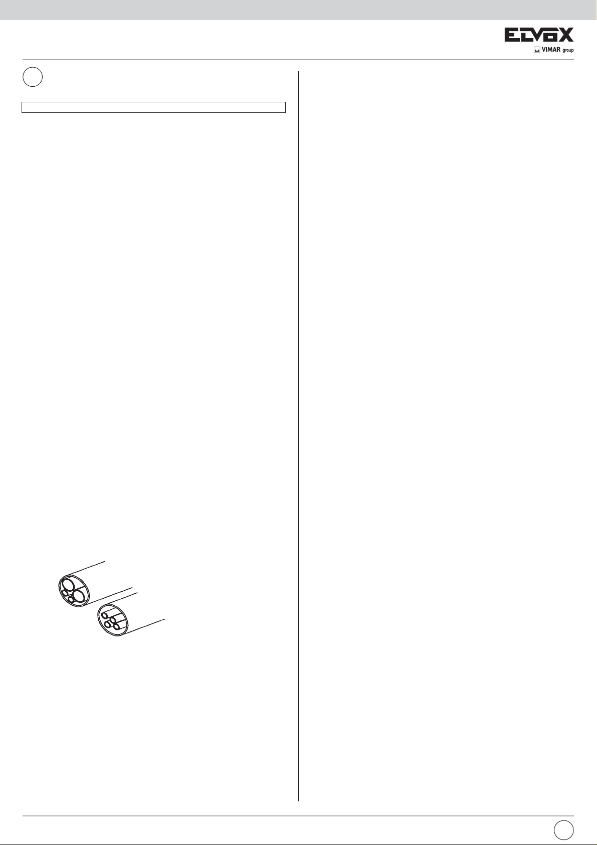
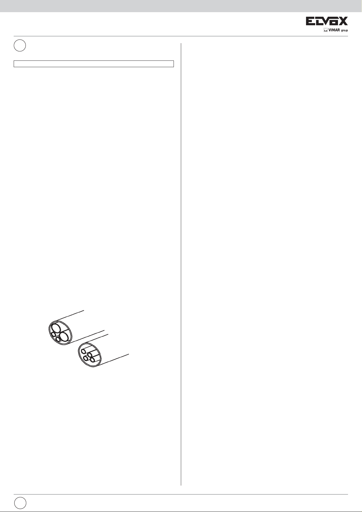
Tubazione cavi energia
Tubazione cavi DIGIBUS
CARATTERISTICHE TECNICHE DELL’ALIMENTATORE ART. 6948
Alimentatore base per tutti gli impianti videocitofoni DIGIBUS con custodia in
tecnopolimero classe V-0 predisposto per montaggio su quadri con barra DIN ad
omega con ingombro di dodici moduli oppure fissaggio a parete tramite tasselli.
Realizzato con schede intercambiabili e morsettiere estraibili per assicurare una
rapida manutenzione. L’alimentatore dispone di un generatore di chiamata acustica e di un gruppo di 6 LED per la segnalazione dello stato di funzionamento.
Dati generali dell’alimentatore:
- Dimensioni: 208x135x72
- Peso solo alimentatore: 1,5Kg
- Alimentazione: 230V ca (+6/-10%) 50-60Hz (a richiesta alimentazioni
diverse)
- Potenza massima assorbita: 60VA
- Uscita per alimentazione parte digitale: 13,5Vcc 0,5A ciclo intermittente 90
sec ON 420 sec OFF,
0,5a a ciclo continuo (massimo 10 distributori Art. 949B e una targa video
oppure 60 apparecchi tipo Art. 887B, 6204, 6344, 6554, 6624, 6614 e una
targa video)
- Uscita per alimentazione monitor: 18Vcc 0,8A ciclo intermittente 90 sec ON
420 sec OFF (massimo due monitor in parallelo).
- Uscita per serratura: 15V rettificati 1A ciclo intermittente 30 sec ON 480
sec OFF.
- Uscite per attivazione funzione supplementari: 12Vcc 0,15A ciclo
intermittente 255 sec ON 255 sec OFF (massimo 1 relè tipo 0170/001,
ecc.).
Protezioni inserite nell’alimentatore:
- Avvolgimento primario trasformatore: PTC tipo SIEMENS C840
- 1° avvolgimento secondario trasformatore per alimentazione elettronica
interna: Fusibile F 3,15AL 250V (F1)
- 2° avvolgimento secondario trasformatore per alimentazione serratura e/o
lampade: PTC tipo SIEMENS C945
- Generatore di chiamata elettronica: PTC tipo SIEMENS C945
- Protezione elettronica da sovraccarichi o cortocircuiti sul montante monitor
o targhe.
Controlli visivi tramite gruppo LED:
L1- Alimentazione monitor (morsetti + e -) LED ROSSO
L2 - Comando serratura (morsetto S) LED GIALLO
L3 - Funzione ausiliare 1 (morsetto F1) LED VERDE
L4 - Funzione ausiliare 2 (morsetto F2) LED GIALLO
L5 - Fonica e generatore di chiamata (3) LED VERDE
L6 - Alimentazione circuito digitale (4 e 5) LED ROSSO
Morsetti alimentatore e descrizione di funzionamento:
M1-M2: Morsetti passanti di ancoraggio per calza cavo coassiale.
V1-V2: Morsetti passanti di ancoraggio per anima cavo coassiale
+I: Linea di comando spegnimento monitor.
Il morsetto è utilizzato dalle targhe o dal centralino per spegnere i mo-
nitor prima di una nuova chiamata e alla fine della conversazione. Cortocircuitando il morsetto +I sul morsetto 4 la tensione tra i morsetti + e
- scende a zero volt e rimane a zero per il tempo in cui il morsetto +I è
cortocircuitato. La mancanza di tensione sui morsetti + e - è segnalata
dallo spegnimento del LED L1.
CH: Linea di comando attivazione chiamata acustica.
Il morsetto è utilizzato dalle targhe o dal centralino per attivare il gene-
ratore di nota presente nell’alimentatore. Cortocircuitando il morsetto
CH sul morsetto 4 viene attivato il segnale di chiamata, il quale esce
dal morsetto 3. Il segnale rimane attivato per il tempo in cui il morsetto
CH è cortocircuitato.
S: Linea di comando apertura serratura.
Il morsetto è utilizzato dalle targhe o dal centralino per aprire la serra-
tura relativa alla targa o al centralino. Cortocircuitando il morsetto S sul
morsetto 4 viene cortocircuitato il morsetto S1 sul morsetto 0 (relativo
ai 15V rettificati) e viene acceso il LED L2. Il morsetto S1 rimane cortocircuitato per il tempo in cui il morsetto S è attivato.
F1: Linea di comando attivazione 1° funzione ausiliare.
Il morsetto è utilizzato dalle targhe o dal centralino per segnalare l’atti-
vazione della funzione F1. Cortocircuitando il morsetto F1 sul morsetto
4 la tensione sul morsetto R1 sale a 12Vcc e rimane a 12V per il tempo
in cui il morsetto F1 è cortocircuitato. L’attivazione della funzione è segnalata dall’accensione del LED L3.
2
IT
Page 3
F2: Linea di comando attivazione 2° funzione ausiliare.
Il morsetto è utilizzato dalle targhe o dal centralino per segnalare l’atti-
vazione della funzione F2. Cortocircuitando il morsetto F2 sul morsetto
4 la tensione sul morsetto R2 sale a 12Vcc e rimane a 12V per il tempo
in cui il morsetto F2 è cortocircuitato. L’attivazione della funzione è segnalata dall’accensione del LED L4.
3: Linea di chiamata e fonica.
Il morsetto è utilizzato per inviare il segnale di chiamata lungo il mon-
tante e per segnalare la presenza di apparecchi inseriti con microtelefono sollevato. Quando viene attivato il morsetto CH, dal morsetto 3
esce il segnale modulato di chiamata e si accende il LED L5. Nel caso
in cui il morsetto CH è inattivo, la linea del morsetto 3 segnala che c’è
la presenza di uno o più citofoni (monitor) inseriti con microtelefono
sollevato tramite l’accensione del LED L5.
4: Linea negativo per alimentazione circuito digitale.
5: Linea +13,5Vcc 0,5A a ciclo continuo 0,5A a ciclo intermittente per
alimentazione circuito digitale.
La presenza di tensione sul morsetto 5 è segnalata dall’accensione del
LED L6.
-: Linea negativo per alimentazione monitor.
+: Linea +18Vcc 0,8A per alimentazione monitor.
La presenza di tensione sul morsetto + è segnalata dall’accensione del
LED L1.
4: Linea negativo per funzioni ausiliari.
R1: Linea +12Vcc 0,15A per funzione ausiliare 1.
Il morsetto è utilizzato per attivare un relè con l’azionamento della fun-
zione F1. Quando il morsetto F1 è attivato, sul morsetto R1 è presente
una tensione di 12Vcc.
4: Linea negativo per funzioni ausiliari.
R2: Linea +12Vcc 0,15A per funzione ausiliare 2.
Il morsetto è utilizzato per attivare un relè con l’azionamento della fun-
zione F2. Quando il morsetto F2 è attivato, sul morsetto R2 è presente
una tensione di 12Vcc.
S1: Linea per apertura serratura 1A.
Quando il morsetto S è attivato, il morsetto S1 viene cortocircuitato sul
morsetto 0.
La linea è protetta da una PTC tipo SIEMENS C945.
15 - 0: Linea 15V rettificati 1A per apertura serratura.
Morsetti per serratura e servizi.
La linea è protetta da una PTC tipo SIEMENS C945.
PRIM: Morsetti di alimentazione: 230Vca +6/-10% 50-60Hz
Questi morsetti sono posti sotto la protezione in materiale termoplastico
PROGRAMMAZIONE DEL NUMERO UTENTE PER CITOFONI, MONITOR E
DISTRIBUTORI DIGITALI.
Se l’impianto prevede il collegamento di targhe in parallelo, solamente per la
fase di programmazione del numero utente è opportuno scollegare le targhe
che hanno il ponte ON-OFF tagliato (o in posizione OFF).
L’utilizzo delle targhe Art. 8843, 8845, 8844, 8847, 8943, 8945, 943/…, 943/5...
per la programmazione dei citofoni o dei monitor deve avvenire dopo aver programmato ogni tasto della targa. Eseguire la programmazione degli apparecchi
uno per volta.
Programmazione citofoni e monitor con codifica interna Art. 887B, 887B/1,
6204, 62K4, 6304, 6324, 6504 per mezzo della targa.
1) Premere per un momento il pulsante di programmazione presente nel cito-
fono o nei monitor (vedi figure di pagina seguente).
2) Premere successivamente il tasto
posto vicino al pulsante di programmazione.
3) Se il LED non si accende ripetere l’operazione dal punto 1.
4) Sollevare il microtelefono dell’apparecchio e verificare il collegamento
audio con la targa.
5) Comporre sulla targa il numero con il quale programmare l’apparecchio e
inviare la chiamata tramite il tasto “C”.
6) Attendere lo spegnimento del LED nel citofono/monitor come conferma
della programmazione.
7) Proseguire la programmazione degli altri apparecchi dal punto 1.
fino all’accensione del LED
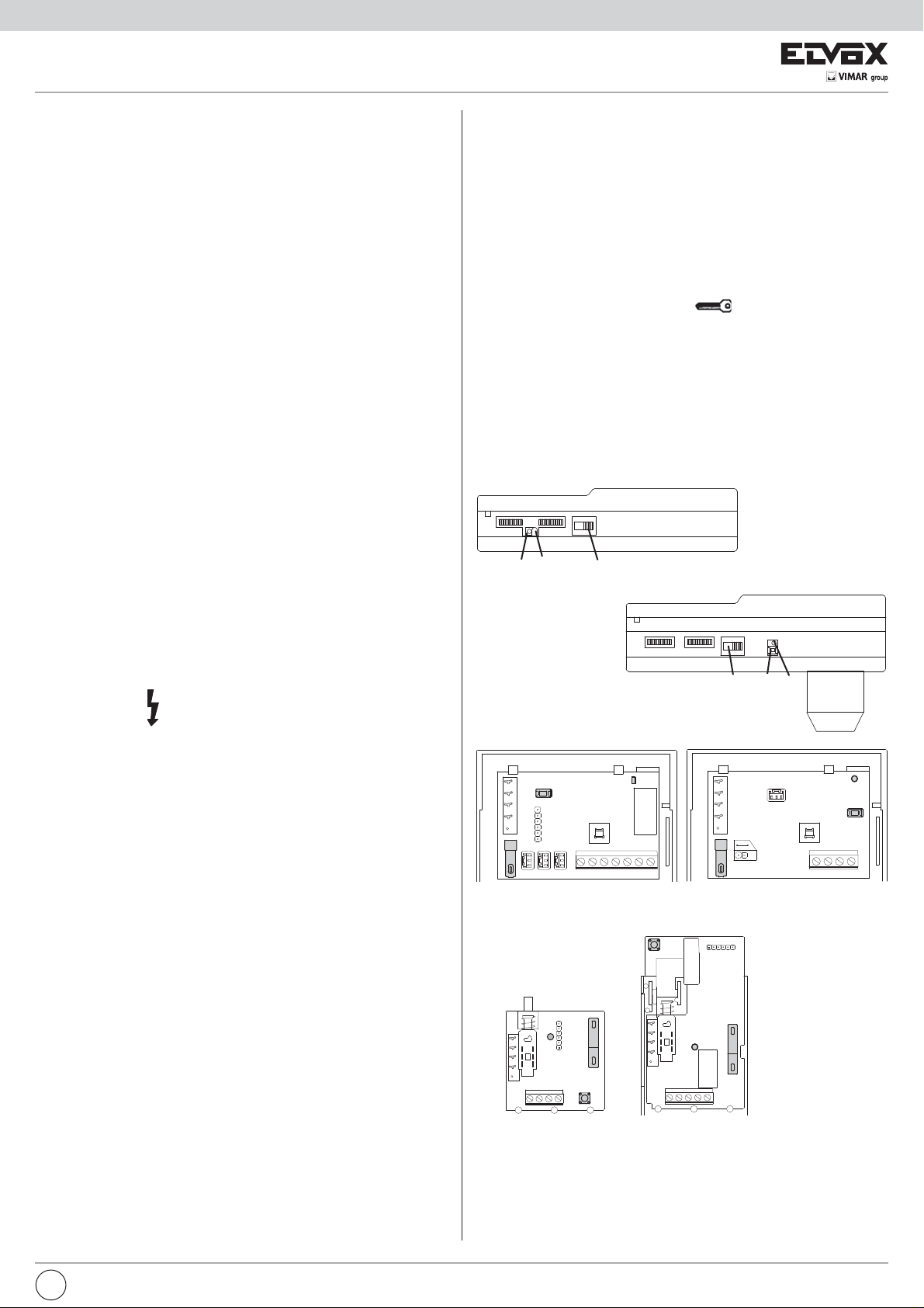
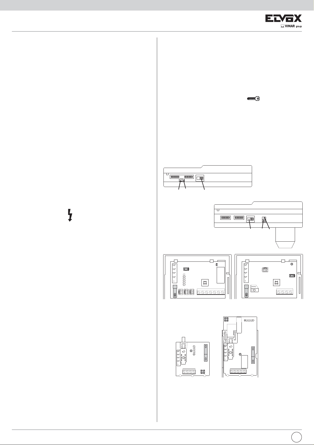
Lato inferiore del monitor Art. 6304, 6324
B
A
D
Lato inferiore del monitor Art. 6504
A
B
D
con simbolo
sente il morsetto di messa a terra in quanto trattasi di alimentatore costruito in classe 2.
OPERAZIONI PRELIMINARI
Eseguita l’installazione totale degli apparecchi e il loro collegamento dare alimentazione al sistema, verificare tramite i LED posti sugli alimentatori, la presenza di tensione sull’impianto. Nel caso degli alimentatori Art. 6941, 6942,
6947 la verifica avviene tramite l’accensione del solo LED rosso L6, mentre per
l’alimentatore Art. 6948 si ha l’accensione dei LED rossi L1 e L6. Prima di effettuare qualsiasi programmazione sugli apparecchi attendere almeno una decina
di secondi dal momento in cui è stata data tensione all’impianto.Successivamente verificare ed eventualmente programmare i parametri di funzionamento
delle targhe e/o del centralino.
E’ da tenere presente che le targhe e il centralino dispongono già di una impostazione base fornita in fabbrica, tale impostazione dev’essere vagliata in
funzione delle esigenze dell’impianto. Per la programmazione delle targhe e del
centralino fare riferimento alle istruzioni allegate agli apparecchi. Impostati i parametri di funzionamento delle targhe e del centralino, eseguire la programmazione numero utente dei citofoni e dei monitor. Se l’impianto è di tipo complesso
edilizio è opportuno eseguire la programmazione del numero utente per mezzo
delle targhe a piè scala (secondarie).
e sono utilizzati per il collegamento a rete. Non è pre-
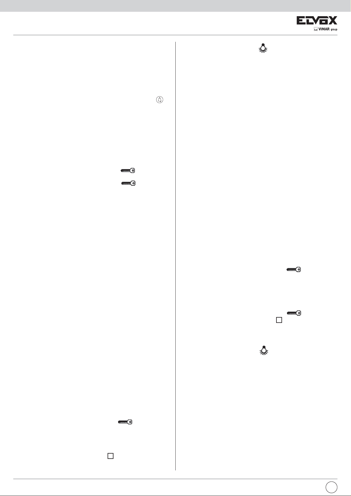
B
A
B
C
F
C
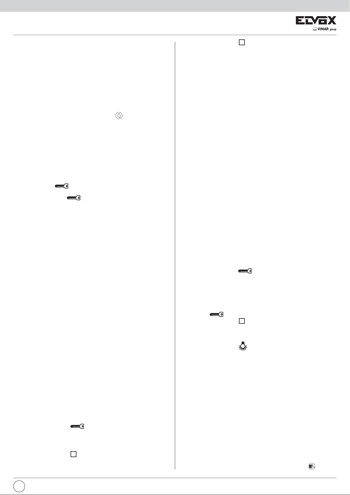
Art. 6204
Art. 62K4
B
Art. 887B/1
D
D
C
C
A
B
A- LED interno di indicazione stato programmazione/attivazione fonica
B- Pulsante reset/programmazione
C- Pulsante serratura
D- Selettore a 4 posizioni (solo su Art. 887B e 887B/1)
F- Jumper volume suoneria alto/basso (solo su Art. 62K4)
A
Art. 887B
A
IT
3
Page 4

NOTE DI FUNZIONAMENTO E PROGRAMMAZIONE DEI CITOFONI ART.
62K4 EART. 887B/1
Segnale di chiamata
I citofoni Art. 62K4 e Art. 887B/1 nella versione base hanno il segnale di chiamata sull’altoparlante del citofono, ovviamente allo sgancio del microtelefono
dalla sua apposita sede il segnale di chiamata si interrompe.
Il citofono genera internamente il segnale di chiamata e la relativa durata;
tuttavia è possibile modificare i parametri di chimata ( frequenza audio: alta ,
media , bassa; durata del segnale: breve, media , allungata) ottenendo nove
melodie diverse in tipo e durata selezionabili, entrando nel menù di programmazione parametri di chiamata, nella seguente sequenza:
a) frequenza alta e durata breve;
b) frequenza alta e durata media;
c) frequenza alta e durata allungata;
d) frequenza media e durata breve;
e) frequenza media e durata media;
f) frequenza media e durata allungata;
g) frequenza bassa e durata breve;
h) frequenza bassa e durata media;
i) frequenza bassa e durata allungata;
Opzione regolazione volume suoneria suoneria (solo per citofono 62K4)
Il citofono Art. 62K4 ha inoltre la possibilità di impostare due differenti livelli
di volume della suoneria di chiamata; agendo sul Jumper “CN6 - VOL” (riferimento “F” della figura) si modifica il volume nelle seguenti due modalità:
- jumper inserito = volume di suoneria alto
- jumper disinserito = volume di suoneria basso
Procedura di programmazione parametri di chiamata per citofono 62K4
1) Premere per un momento il pulsante di programmazione presente nel cito-
fono.
2) Premere successivamente il tasto
rosso, mantenendolo premuto per ulteriori 5 secondi, fino a che il LED rosso
passa da acceso a lampeggiante.
3) Se il LED rosso non diventa lampeggiante, ripetere l’operazione dal punto
1.
4) Il citofono inizia a riprodurre la melodia correntemente impostata. Premendo
ripetutamente il tasto serratura “C” si possono selezionare in sequenza 9
melodie differenti in tipo e durata.
5) Una volta scelta la melodia desiderata e sufficiente attendere lo spegnimento del LED rosso nel citofono come conferma della programmazione
avvenuta.
Procedura di programmazione parametri di chiamata per citofono 887B/1
Per accedere al menù di programmazione parametri di chiamata:
1) premere contemporaneamente per circa cinque secondi i due tasti del citofono: il citofono attiverà la prima chiamata (frequenza alta e durata breve);
2) pressioni ripetute del tasto relativo alla funzione ausiliaria F1 (2° tasto)
permetterà di generare differenti tipologie di chiamata (come frequenza e
durata).
3) la pressione del tasto relativo alla funzione serratura (1° tasto) permetterà
di confermare e salvare la scelta fatta del tipo di chiamata;
4) se non vengono premuti i tasti per almeno venti secondi, il citofono uscirà
dalla programmazione parametri di chiamata e ritornerà nello stato normale
di funzionamento.
Programmazione distributori digitali Art 949B per mezzo della targa.
1) Premere per un momento il pulsante PS1 presente sul distributore digitale.
2) Premere successivamente sul distributore il pulsante PS2 fino all’accen-
sione del primo dei quattro LED, posti sul distributore stesso.
3) Se il LED non si accende ripetere l’operazione dal punto 1.
4) Sollevare il microtelefono del citofono o del monitor collegati ai morsetti A1 e
A3 del distributore in oggetto e verificare il collegamento audio con la targa.
5) Comporre sulla targa il numero con il quale programmare l’apparecchio e
inviare la chiamata tramite il tasto “C”.
6) Attendere lo spegnimento del LED nel citofono/monitor come conferma
della programmazione.
7) Per proseguire alla programmazione degli altri 3 derivati (citofoni o monitor)
collegati al distributore in questione, premere nuovamente il pulsante PS1
e successivamente mantenere premuto il pulsante PS2 fino all’accensione
del secondo o del terzo oppure del quarto LED.
8) L’accensione dei LED indica quale derivato è in fase di programmazione
secondo la seguente tabella:
LED1 ¬ ® Morsetti A1 e A3
LED2 ¬ ® Morsetti B1 e B3
LED3 ¬ ® Morsetti C1 e C3
LED4 ¬ ® Morsetti D1 e D3
9) Continuare la programmazione degli apparecchi ripetendo per ognuno la
procedura come descritto dal punto 1.
fino all’accensione del LED
CENTRALINO Art. 945B E Art. 955.
La programmazione del numero da associare ai citofoni o ai monitor, utilizzando
il centralino, avviene nel seguente modo:
· Posizionare il centralino nella modalità interno.
· Sollevare il microtelefono del centralino e premere il tasto
accendere la spia relativa al tasto
· Senza agganciare il microtelefono del centralino, effettuare la programmazione del citofono o del monitor oppure del distributore:
Programmazione citofoni e monitor con codifica interna Art. 887B, 887B/1,
6204, 6304, 6324, 6504.
1) Premere per un momento il pulsante di programmazione presente nel cito-
fono o nei monitor (vedi figure seguenti).
2) Premere successivamente il tasto
posto vicino al pulsante di programmazione.
3) Se il LED non si accende ripetere l’operazione dal punto 1.
4) Sollevare il microtelefono dell’apparecchio e verificare il collegamento audio
con il centralino.
5) Comporre sul centralino il numero con il quale programmare l’apparecchio
e inviare la chiamata tramite il tasto
6) Attendere lo spegnimento del LED nel citofono/monitor come conferma
della programmazione.
7) Proseguire la programmazione degli altri apparecchi dal punto 1.
N.B.: è da tenere presente che il collegamento audio tra centralino e il citofono
avviene solamente quando la spia del tasto
vesse essere spenta premere nuovamente il tasto
per il quale la spia rimane accesa è il tempo di conversazione massimo impostato nel centralino.
Programmazione distributori digitali Art 949B.
1) Premere per un momento il pulsante PS1 presente sul distributore digitale.
2) Premere successivamente sul distributore il pulsante PS2 fino all’accen-
sione del primo dei quattro LED, posti sul distributore stesso.
3) Se il LED non si accende ripetere l’operazione dal punto 1.
4) Sollevare il microtelefono del citofono o del monitor collegati ai morsetti
A1 e A3 del distributore in oggetto e verificare il collegamento audio con il
centralino.
5) Comporre sul centralino il numero con il quale programmare l’apparecchio
e inviare la chiamata tramite il tasto
6) Attendere lo spegnimento del LED nel citofono/monitor come conferma
della programmazione.
7) Per proseguire alla programmazione degli altri 3 derivati (citofoni o monitor)
collegati al distributore in questione, premere nuovamente il pulsante PS1
e successivamente mantenere premuto il pulsante PS2 fino all’accensione
del secondo o del terzo oppure del quarto LED.
8) L’accensione dei LED indica quale derivato è in fase di programmazione
secondo la seguente tabella:
LED1 ¬ ® Morsetti A1 e A3
LED2 ¬ ® Morsetti B1 e B3
LED3 ¬ ® Morsetti C1 e C3
LED4 ¬ ® Morsetti D1 e D3
9) Continuare la programmazione degli apparecchi ripetendo per ognuno la
procedura come descritto dal punto 1.
N.B.: è da tenere presente che il collegamento audio tra centralino e il monitor
avviene solamente quando la spia del tasto
vesse essere spenta premere nuovamente il tasto
per il quale la spia rimane accesa è il tempo di conversazione massimo impostato nel centralino.
.
fino all’accensione del LED
.
è accesa, perciò se la spia do-
per accenderla. Il tempo
.
è accesa, perciò se la spia do-
per accenderla. Il tempo
, in modo da
PROGRAMMAZIONE CITOFONI, MONITOR E DISTRIBUTORI DIGITALI DAL
4
IT
Page 5
FUNZIONAMENTO IMPIANTO
Negli impianti videocitofonici della serie DIGIBUS è utilizzato come alimentatore
base l’Art. 6948.
Questo permette di alimentare i monitor, i citofoni, i distributori digitali, le targhe
e il centralino.
Nel caso che l’impianto lo richieda, per motivi di linea lunga o per quantità di apparecchi oppure per cadute di tensione, si possono utilizzare i seguenti alimentatori supplementari: Art. 6942 per alimentare le targhe, il centralino, i distributori
digitali, i citofoni e i monitor (per il circuito digitale); Art. 6947 per alimentare i
monitor e per rigenerare il segnale di chiamata.
Per la disposizione degli alimentatori fare riferimento agli schemi relativi all’impianto.
Le chiamate da targa o da centralino verso gli apparecchi, citofoni o monitor,
avvengono componendo sulla tastiera della targa o del centralino il numero
dell’interno e poi premendo il tasto C oppure il tasto
Per annullare le chiamate premere il tasto R. Una volta premuto il tasto di chiamata, la targa o il centralino invierà il codice digitale che permetterà di inserire l’interno. Successivamente la prima targa o il primo centralino collegato al
montante monitor (o citofoni), toglieranno momentaneamente l’alimentazione
sui morsetti + e - del montante, in modo da spegnere eventuali monitor accesi,
attiveranno il generatore di chiamata dell’alimentatore per il tempo di chiamata
impostato su di essi, e invieranno il segnale di chiamata verso il montante. Al
termine della chiamata il citofono o il monitor si collegheranno fonicamente con la
targa esterna oppure con il centralino. Nel caso di monitor e targa video oppure
di monitor e centralino con telecamera, sul monitor si visualizzerà rispettivamente
l’immagine ripresa dalla targa o dalla telecamera del centralino.
Una volta inseriti il citofono o il monitor da questi si potrà: aprire la serratura della
targa tramite il tasto
Le funzioni supplementari si potranno attivare indipendentemente se l’interno è
inserito o no; però il tasto
l’interno è in collegamento con la targa esterna, altrimenti effettuerà la chiamata
al centralino portineria. Effettuata la chiamata, il collegamento tra gli apparecchi
perdurerà per il tempo di attesa (impostato sulla targa o sul centralino), se il microtelefono non viene sollevato oppure per il tempo di conversazione se gli apparecchi si mettono in conversazione tra loro. Agganciando il microtelefono
prima dello scadere del tempo di conversazione, il citofono o il monitor si scollegheranno dopo circa 5”.
DESCRIZIONE IMPIANTI TIPO:
Qui di seguito sono stati descritti tre impianti tipo videocitofoni DIGIBUS che
utilizzano l’alimentatore Art. 6948.
Nel caso dell’utilizzo delle due funzioni ausiliari si deve prevedere il collegamento
rispettivo dei morsetti F1 o F2 della targa (o centralino), con quelli dell’alimentatore. L’utilizzo delle due funzioni ausiliari con i citofoni e i monitor Art. 8877, 6201,
6327 richiede il collegamento delle funzioni tra il citofono/monitor e il distributore
digitale Art. 949B.
A) Impianto tipo videocitofono con una targa video (vedi disegno SI212).
B) Impianto tipo videocitofono per complesso edilizio con targa principale video
e targhe secondarie video/audio (vedi disegno SI177).
C) Impianto tipo videocitofono con una targa video e centralino portineria mu-
nito di monitor e telecamera (vedi disegno si176).
A) Impianto tipo videocitofono con una targa video (schema SI212).
- Composizione sulla tastiera della targa del numero riferito all’utente, esempio.
77.
- Pressione del tasto C.
- Attivazione del morsetto +L della targa.
- Invio sulla linea 1 del codice digitale relativo al numero 77 verso il montante
monitor.
- Attivazione per un breve momento del morsetto +I e spegnimento di eventuali
monitor accesi.
- Collegamento circuito fonica del monitor con codice 77 al montante.
- Attivazione del morsetto CH della targa per il tempo di chiamata e invio del
segnale di chiamata lungo la linea 3 del montante.
- Collegamento del circuito fonica della targa dopo il tempo di chiamata.
- Se il microtelefono del monitor non viene sollevato, la targa conteggia il tempo
di attesa.
- Se il microtelefono del monitor viene sollevato prima dello scadere del tempo
di attesa, la targa inizia a conteggiare il tempo di conversazione massimo.
- Sia con microtelefono a riposo o sollevato si possono attivare le due funzioni
supplementari e l’apertura serratura. Comunque le due funzioni supplementari
possono essere attivate anche se il monitor non è stato chiamato.
Se viene premuto il tasto il monitor invierà sul montante, il codice di
apertura serratura con il proprio numero (77); la targa da cui è stata effettuata
la chiamata, riconosciuto il codice attiverà di conseguenza il morsetto S per il
tempo serratura, impostato su di essa. Pertanto il morsetto S1 dell’alimentatore
andrà a zero volt per il tempo che il morsetto S rimane attivato.
- Se viene premuto il tasto il monitor invierà sul montante, il codice della
funzione supplementare F2 con il proprio numero (77); la targa riconosciuto il
codice attiverà di conseguenza il morsetto F2 per il tempo F2.
.
aprirà la serratura della targa solamente se
.
- Se viene premuto il tasto il monitor invierà sul montante, il codice della
funzione supplementare F1 con il proprio numero (77); la targa riconosciuto il
codice attiverà di conseguenza il morsetto F1 per il tempo F1.
- Scaduto il tempo di attesa o di conversazione, la targa in collegamento con il
monitor invierà un codice di azzeramento per disinserire il monitor e di conseguenza attiverà il morsetto +I per spegnere il monitor.
Lo stesso avvenimento accade quando viene agganciato il microtelefono del
monitor prima dello scadere del tempo di conversazione, dopo circa 5” che il
microtelefono è stato agganciato la targa invia un codice di azzeramento e
attiva il morsetto +I.
B) Impianto tipo videocitofono per complesso edilizio con targa principale
video e targhe secondarie video/audio (schema SI177).
- Composizione sulla tastiera della targa principale del numero riferito all’utente,
esempio 77.
- Pressione del tasto C.
- Attivazione del morsetto +L della targa principale.
- Invio sulla linea 1 del codice digitale relativo al numero 77 verso il montante.
- Riconoscimento del codice digitale di chiamata, relativo al numero 77 da parte
di tutte targhe secondarie. Se il codice di chiamata (77), è compreso tra il
numero minimo e massimo di una delle targhe secondarie, la targa relativa si
comporterà nel seguente modo.
- Posizionamento della targa secondaria nello stato di “OCCUPATO-ATTENDERE”.
- Attivazione momentanea del morsetto +I della targa secondaria e spegnimento di eventuali monitor accesi.
- Rigenerazione e ripetizione del codice di chiamata relativo al numero 77 verso
il montante monitor.
- Collegamento circuito fonica del monitor con codice 77 al montante.
- Attivazione del morsetto CH della targa secondaria per il tempo di chiamata,
impostato nella targa secondaria e invio del segnale di chiamata lungo la linea
3 del montante.
- Collegamento del circuito fonica della targa principale dopo il tempo di chiamata, impostato nella targa principale.
- Se il microtelefono del monitor non viene sollevato, la targa principale conteggia il tempo di attesa.
- Se il microtelefono del monitor viene sollevato prima dello scadere del tempo
di attesa, la targa principale inizia a conteggiare il tempo di conversazione
massimo.
- Sia con microtelefono a riposo o sollevato si possono attivare le due funzioni
supplementari e l’apertura serratura. Comunque le due funzioni supplementari
possono essere attivate anche se il monitor non è stato chiamato.
- Se viene premuto il tasto
apertura serratura con il proprio numero (77); la targa principale da cui è stata
effettuata la chiamata, riconosciuto il codice attiverà di conseguenza il morsetto S per il tempo serratura, impostato in essa. Pertanto il morsetto S1
dell’alimentatore andrà a zero volt per il tempo che il morsetto S rimane attivato.
- Se la targa secondaria, che ha ripetuto la chiamata, ha il parametro abilita
serratura a 0001 anch’essa attiverà il proprio morsetto S quando si premerà
il pulsante
- Se viene premuto il tasto
funzione supplementare F2 con il proprio numero (77); la targa secondaria e
quella principale riconosciuto il codice attiveranno i propri morsetti F2 per il
tempo F2.
- Se viene premuto il tasto
funzione supplementare F1 con il proprio numero (77); la targa secondaria e
quella principale riconosciuto il codice attiveranno i propri morsetti F1 per il
tempo F1.
- Scaduto il tempo di attesa o di conversazione, la targa principale in collega-
mento con il monitor invierà un codice di azzeramento per disinserire il monitor. Di conseguenza la targa secondaria attiverà il morsetto +I per spegnere il
monitor e uscirà dallo stato di “OCCUPATO-ATTENDERE”.
- Lo stesso avvenimento accade quando viene agganciato il microtelefono del
monitor, prima dello scadere del tempo di conversazione, dopo circa 5” che il
microtelefono è stato agganciato la targa principale invierà un codice di azzeramento e la targa secondaria attiverà il morsetto +I.
- Nello stesso tempo che la targa principale è in conversazione con un monitor,
dalle altre targhe secondarie che non sono nello stato di “OCCUPATO-ATTENDERE” si possono chiamare i monitor o i citofoni.
N.B.: in un impianto per complesso edilizio, è da tenere presente che il tempo
di attivazione della suoneria, della targa principale dev’essere maggiore del
tempo delle targhe secondarie di almeno un secondo, per evitare il ritorno del
segnale di chiamata nel ricevitore della targa principale.
C) Impianto tipo videocitofono con una targa video e centralino portineria
munito di monitor e telecamera (schema si176).
Con centralino portineria in posizione ESTERNO ( spia del tasto
.
il monitor invierà verso la targa, il codice di
il monitor invierà sul montante il codice della
il monitor invierà sul montante il codice della
accesa)
IT
5
Page 6
- Composizione sulla tastiera della targa principale del numero riferito all’utente,
esempio 77.
- Pressione del tasto C.
- Attivazione del morsetto +L della targa.
- Invio sulla linea 1 del codice digitale relativo al numero 77 verso il montante.
- Riconoscimento del codice digitale di chiamata da parte del centralino portineria e attivazione momentanea del morsetto +I per il spegnimento di eventuali
monitor accesi.
- Visualizzazione sul centralino della scritta “STOP”.
- Attivazione del morsetto I del centralino, per mantenere il monitor del centralino spento.
- Rigenerazione e ripetizione del codice di chiamata relativo al numero 77 verso
il montante monitor.
- Collegamento circuito fonica del monitor con codice 77 al montante.
- Attivazione del morsetto CH del centralino per il tempo di chiamata, impostato
nel centralino e invio del segnale di chiamata lungo la linea 3 del montante.
- Collegamento del circuito fonica della targa dopo il tempo di chiamata, impostato nella targa stessa.
- Se il microtelefono del monitor non viene sollevato, la targa conteggia il tempo
di attesa.
- Se il microtelefono del monitor viene sollevato prima dello scadere del tempo
di attesa, la targa inizia a conteggiare il tempo di conversazione massimo.
- Sia con microtelefono a riposo o sollevato si possono attivare le due funzioni
supplementari e l’apertura serratura. Comunque le due funzioni supplementari
possono essere attivate anche se il monitor non è stato chiamato.
- Se viene premuto il tasto
apertura serratura con il proprio numero (77); la targa da cui è stata effettuata
la chiamata riconosciuto il codice attiverà di conseguenza il morsetto S per il
tempo serratura, impostato in essa. Pertanto il morsetto S1 dell’alimentatore
andrà a zero volt per il tempo che il morsetto S rimane attivato.
- Se il centralino ha il parametro abilita serratura, a 0001 anch’esso attiverà il
proprio morsetto S quando il monitor premerà il pulsante
- Se viene premuto il tasto
funzione supplementare F2 con il proprio numero (77); il centralino e la targa
riconosciuto il codice attiveranno i propri morsetti F2 per il tempo F2.
- Se viene premuto il tasto
funzione supplementare F1 con il proprio numero (77); il centralino e la targa
riconosciuto il codice attiveranno i propri morsetti F1 per il tempo F1.
- Scaduto il tempo di attesa o di conversazione, la targa principale in colle-
gamento con il monitor invierà un codice di azzeramento per disinserire il
monitor. Di conseguenza il centralino attiverà il morsetto +I per spegnere il
monitor e cancellerà la scritta STOP.
- Lo stesso avvenimento accade quando viene agganciato il microtelefono del
monitor prima dello scadere del tempo di conversazione, dopo circa 5” che il
microtelefono è stato agganciato la targa invierà un codice di azzeramento e
il centralino attiverà il morsetto +I.
il monitor invierà sul montante, il codice di
.
il monitor invierà sul montante, il codice della
il monitor invierà sul montante, il codice della
- Invio sulla linea 1 del codice digitale relativo alla chiamata portineria con il
numero del monitor, esempio 77.
- Visualizzazione del numero 77 sul display di sinistra del centralino e attivazione segnale sonoro di chiamata.
- Se il centralinista vuole chiamare il monitor che ha effettuato la chiamata si
deve comportare nel seguente modo:
- Trasferimento del numero 77 sul display di destra attraverso il tasto
- Pressione del tasto con
- Invio sulla linea 1 del codice digitale relativo al numero 77 verso il montante.
- Attivazione morsetto T del centralino, per l’accensione della telecamera.
- Se il morsetto I del centralino è attivo, disattivazione del morsetto.
- Attivazione momentanea del morsetto +I e spegnimento di eventuali monitor
accesi.
- Collegamento circuito fonica del monitor con codice 77 al montante.
- Attivazione del morsetto CH del centralino per il tempo di chiamata, e invio del
segnale di chiamata lungo la linea 3 del montante.
- Collegamento del circuito fonica del centralino dopo il tempo di chiamata.
- Se il microtelefono del monitor non viene sollevato, il centralino conteggia il
tempo di attesa.
- Se il microtelefono del monitor viene sollevato prima dello scadere del tempo
di attesa, il centralino inizia a conteggiare il tempo di conversazione massimo.
- Sia con microtelefono a riposo o sollevato si possono attivare le due funzioni
supplementari. Comunque le due funzioni supplementari possono essere attivate anche se il monitor non è stato chiamato.
- Scaduto il tempo di attesa o di conversazione, il centralino in collegamento
con il monitor invierà un codice di azzeramento per disinserire il monitor, attiverà il morsetto +I per spegnere il monitor del montante, attiverà il morsetto
I per spegnere il proprio monitor e disattiverà il morsetto T per spegnere la
propria telecamera.
- Lo stesso avvenimento accade quando viene riagganciato il microtelefono del
monitor prima dello scadere del tempo di conversazione, dopo circa 5” che
il microtelefono è stato riagganciato il centralino invierà un codice di azzeramento e attiverà i relativi morsetti.
- N.B.: In un impianto con targa principale e centralino, è da tenere presente
che il tempo di attivazione della suoneria, della targa principale dev’essere
maggiore del tempo del centralino di almeno un secondo, per evitare il ritorno
del segnale di chiamata nel ricevitore della targa principale.
.
.
Con centralino portineria in posizione INTERNO ( spia del tasto
chiamata da targa:
- Composizione sulla tastiera della targa principale del numero riferito all’utente, esempio 77.
- Pressione del tasto C.
- Attivazione del morsetto +L della targa.
- Invio sulla linea 1 del codice digitale relativo al numero 77 verso il montante.
- Visualizzazione del numero 77 sul display di destra del centralino e attivazione segnale sonoro di chiamata.
- Se il morsetto I del centralino è attivo, disattivazione del morsetto.
- Accensione monitor centralino con visualizzazione dell’immagine ripresa da
targa.
- Collegamento circuito fonica del centralino con la targa.
- Se il microtelefono del centralino non viene sollevato, la targa conteggia il
tempo di attesa.
- Se il microtelefono del centralino viene sollevato prima dello scadere del
tempo di attesa, la targa inizia a conteggiare il tempo di conversazione massimo.
- Se viene premuto il tasto
supplementare F2; la targa riconosciuto il codice attiverà di conseguenza il
morsetto F2 per il tempo F2.
- Scaduto il tempo di attesa o di conversazione la targa principale invierà un
codice di azzeramento per scollegarsi dal centralino. Di conseguenza il centralino attiverà il morsetto I per spegnere il proprio monitor.
- Lo stesso avvenimento accade quando viene agganciato il microtelefono del
centralino prima dello scadere del tempo di conversazione, dopo circa 5” che
il microtelefono è stato agganciato la targa invierà un codice di azzeramento
e il centralino attiverà il morsetto I.
Con centralino portineria in posizione INTERNO e chiamata da monitor (o ci-
tofono):
- Con monitor disinserito (spento), pressione del tasto
il centralino invierà il codice della funzione
spenta) e
.
6
IT
Page 7
EN
The instruction manual is downloadable from the site www.vimar.com
POWER SUPPLY INSTALLATION
The power supply must be installed in a dry place away from direct heat or dust.
Ensure easy access for inspection and maintenance. Secure the unit to the wall
with the anchor bolts provided or insert it into a rack with a omega DIN bar. Before connecting the unit use a tester to make sure that the cables are not broken
or short-circuited. For user safety, the equipment operates at a low voltage and
is separated from the mains by a high-insulation transformer. We recommend
installation of an overload cutout of appropriate capacity between the mains and
the unit. To complete the installation, proceed as follows:
1) Make the cabling connections to the terminal block in accordance with the
diagrams enclosed with this manual.
2) Connect up the power terminal block located beneath the rear cover.
3) Power up the power supplier. Once correctly powered up, only the red “power-on” LEDS (L1 to L6) for the entrance panel, interphones and monitors
must be illuminated.
The same rule also applies to all the other units in the system. In the case
of entrance panels equipped with video camera and external video camera
units, due consideration must also be given to the following:
4) The video camera operates within a temperature range of -5° to +50°C. To
prevent the unit from overheating, it must therefore be protected from the
sun’s rays by a roof or shield.
5) The lens must not be exposed to direct light beams (sun rays, car headlights
etc.).
6) The caller must be illuminated frontally. If lighting is insufficient, use a supplementary external lamp powered from the mains.
GENERAL CABLE INSTALLATION INSTRUCTIONS
Correct DIGIBUS installation requires the following factors to be taken into account:
- the installation site
- the size of the installation
The equipment is fully compliant with the “CE” mark and directives 2004/108/CE
and the following regarding the Community safety standards and the electromagnetic compatibility. Nonetheless, for correct installation, the following precautions
must be taken:
- the system cables must be layed taking into account the overall length of the
system cabling; the cross-section of the cables increases with the overall
length of the installation as shown in the tables given below.
- the cables connecting the external/internal units and the power supply must
not be run together with power cables (230V or greater), but must be installed
in their own ducts.
TECHNICAL CHARACTERISTICS OF POWER SUPPLIER ART. 6948
The basic power supply unit for all DIGIBUS video electronic door opener systems, housed in a V-0 range technopolimeric case. Designed for mounting to
equipment panels with DIN omega rails (12 modules), or wall fixing with masonry
plugs.
Features inter-changeable cards and pull-out terminal blocks to facilitate rapid
maintenance. The power supplier is fitted with an acoustic call generator and 6
LEDS indicating the operating status.
Main power supplier data:
- Dimensions: 208x135x72
- Power supplier weight: 1,5Kg
- Power supply: 230V A.C. (+6/-10%) 50-60Hz
(other power supplies are available on request)
- Maximum absorbed power: 60VA
- Low voltage supply: 13,5VDC 0,5A intermittent cycle (90 sec. ON 420 sec
OFF), 0,5 A continuous cycle (maximum of 10 distributors Art. 949B and
one video entrance panel, or 60 appliances type Art. 887B, 6204, 6344,
6554, 6624, 6614 and one video entrance panel).
- Monitor supply output: 18VDC 0,8A intermittent cycle (90 sec ON, 420 sec
OFF) (maximum of two monitors connected in parallel).
- Lock output: 15V rectified 1A intermittent cycle (30 sec ON, 480 sec
OFF)
- Outputs for activation of additional functions: 12VDC 0,15A intermittent
cycle (255 sec ON, 255 sec OFF) (maximum of 1 relay type 0170/001,
etc.).
Built-in protection features:
- Transformer primary: PTC tipo SIEMENS C840
- 1st secondary, driving internal electronic circuits: Fusibile F 3,15AL 250V
(F1)
- Secondary transformer winding supplying door lock and/or lamps: PTC tipo
SIEMENS C945
- Generator of electronic call: PTC tipo SIEMENS C945
- Electronic interphone riser or panel short-circuit or overload cutout
LED status indicator unit:
L1 - Monitor power supply (+ and - terminals) RED LED
L2 - Door lock command (terminal S) YELLOW LED
L3 - Auxiliary function 1 (terminal F1) GREEN LED
L4 - Auxiliary function 2 (terminal F2) YELLOW LED
L5 - Phonic line and call generator (3) GREEN LED
L6 - Digital circuit power supply (4 and 5) RED LED
Description of power supplier terminal functions:
Power cable duct
DIGIBUS cable duct
M1-M2 Co-ax cable sheath through terminals.
V1-V2 Co-ax cable core through terminals
+1 Monitor disconnect control line.
This terminal is used by the entrance panels or switchboard to deacti-
vate the monitors before a new call and at the end of a conversation.
When terminal +1 is shorted to terminal 4, the voltage across the +
and - terminals passes through zero and remains at zero for the time
terminal +1 is short-circuited. LED L1 switches off to indicate the “zero
voltage” status of the + and - terminals.
CH Call signal activation control line.
This terminal is used by the entrance panels or switchboard to activate
the call generator in the power supplier. When terminal CH is shorted
to terminal 4, the call signal is activated by terminal 3. The signal remains active for the time terminal CH is short-circuited.
S Door lock release control line.
This terminal is used by the entrance panels or switchboard to release
the door lock for the corresponding entrance panel or switchboard.
When terminal S is shorted to terminal 4, terminal S1 is shorted to
terminal 0 (15V rectified) and LED L2 illuminates. Terminal S1 remains
shorted for the time terminal S is activated.
F1 Auxiliary function 1 activation control line.
This terminal is used by the entrance panels or switchboard to activate
function F1. When terminal F1 is shorted to terminal 4, the voltage at
terminal R1 increases to 12 Vdc and remains at this voltage for the
time terminal F1 is shorted. Activation of the function is signalled by
illumination of LED L3.
EN
7
Page 8
F2 Auxiliary function 2 activation control line.
This terminal is used by the entrance panels or switchboard to activate
function F2. When terminal F2 is shorted to terminal 4, the voltage at
terminal R2 increases to 12 Vdc and remains at this voltage for the time
terminal F2 is shorted. Activation of the function is signalled by illumination of LED L4.
3 Phonic and call signal line.
This terminal routes the call signal along the cable riser and signals the
presence of units with the handset raised (engaged). When terminal CH
is activated, a modulated call signal is transmitted by terminal 3 and LED
L5 illuminates. When terminal CH is de-activated, the line connected to
terminal 3 indicates the presence of one or more interphones (monitors)
with the handset raised (engaged) by illumination of LED L5.
4 Digital circuit power line (negative).
5 Digital circuit power line (+ 13.5 Vdc).
0,5A continuous, 0,5 intermittent
Energisation of terminal 5 is indicated by illumination of LED L6.
- Monitor power line (negative).
+ Monitor power line (+ 18 Vdc 0.8 A).
Energisation of the + terminal is indicated by illumination of LED L1.
4 Auxiliary function power line (negative).
R1 Auxiliary function 1 power line (+ 12 Vdc 0.15 A).
This terminal activates a relay when function F1 is activated. When ter-
minal F1 is activated, terminal R1 is powered by a 12 Vdc voltage.
4 Auxiliary function power line (negative).
R2 Auxiliary function 2 power line (+ 12 Vdc 0.15 A).
This terminal activates a relay when function F2 is activated. When ter-
minal F2 is activated, terminal R2 is powered by a 12 Vdc voltage.
S1 Door lock release line (1A).
When terminal S is activated, terminal S1 is shorted to terminal 0. The
line is protected by a SIEMENS PTC, type C945.
15-0 15V (rectified) line:
These terminals power door lock and services.
1A door lock release.
The line is protected by a SIEMENS PTC, type C945.
PRIM Power terminals: 230 Vac +6/-10% 50-60Hz.
These terminals are mounted under the thermoplastic protection
PROGRAMMING INTERPHONE, MONITOR AND DIGITAL DISTRIBUTOR
USER NUMBERS
If the entrance panels are connected in parallel, disconnect those entry panels on
which the ON-OFF jumper is disconnected (or set to OFF) before programming
the user numbers (it is only necessary to disconnect the panels for programming).
Entrance panels Art. 8843, 8845, 8844, 8847, 8943, 8945, 943/..., 943/5... can
only be used to program the interphones or monitors after each entrance panel
button has first been programmed. This done, program the individual units one
at a time.
Programming interphones and monitors with internal coder Art. 887B,
887B/1, 6204, 62K4, 6304, 6504 from the entrance panel
1) Briefly press the programming button on the interphone or monitor.
2) Press then the door lock release button
programming button illuminates.
3) If the LED does not illuminate, repeat the above steps from point 1.
4) Remove the handset from the unit and check the audio connection with the
entrance panel.
5) From the entrance panel, key in the number with which you wish to program
the internal unit and route the call by pressing button “C”.
6) Wait for the LED switching off on the interphone for the programming confirmation.
7) Program the remaining internal units following the same procedure outlined
above.
until the LED near the
Lower side of monitor Art. 6304 - 6324
B
A
D
Lower side of monitor Art. 6304 - 6324
marked by the symbol
tions. No earth terminal is fitted, this being a power supplier constructed
to Class 2 specifications.
PRELIMINARY OPERATIONS
Following installation and connection of all the units in the system, power up the
installation and make sure all the power suppliers effectively power up (indicated
by illumination of the “power-on” LEDS on the power supplies themselves).
On power suppliers Art. 6941, 6942 and 6947, red LED L6 should illuminate only,
while on power supplier Art. 6948, red LEDS L1 and L6 should both illuminate to
indicate that the system is correctly powered up.
Wait at least ten seconds after powering up the system before programming the
units.
You can then check and, if necessary, program the operating parameters of the
entrance panels and/or switchboard.
The entrance panels and switchboard are factory-set priory to delivery. The parameter settings must therefore be assessed and, if necessary, altered to accommodate specific system requirements. For further information about entrance
panel and switchboard programming, refer to the instructions enclosed with the
units. Once you have set the operating parameters for the entrance panels and
switchboard, program the interphone and monitor user numbers. In the case of
building complex installations, it is a good idea to program the user numbers by
way of the stairway panels (secondary panels).
and are used to power the relay connec-
B
C
Art. 6204
Art. 887B/1
D
A
A
B
D
A
A
B
F
C
Art. 62K4
B
D
C
C
A
B
Art. 887B
A- LED interno di indicazione stato programmazione/attivazione fonica
B- Pulsante reset/programmazione
C- Pulsante serratura
D- Selettore a 4 posizioni (solo su Art. 887B e 887B/1)
F- Jumper volume suoneria alto/basso (solo su Art. 62K4)
8
EN
Page 9

OPERATING AND PROGRAMMING NOTES FOR INTERPHONES TYPE 62K4
AND TYPE 887B/1
Call signal
Interphones type 62K4 and type 887B/1 in the standard version emit the call
signal from the interphone loudspeaker. Obviously when the handset is picked
up, the signal is interrupted.
Procedure for the call parameter programming (only for Art. 887B/1).
The interphone generates the call signal and the respective time dwell internally:
the simultaneous push-button pressure on the interphone for a certain time allows
you to accede to the programming menu of the call parameters (audio frequency:
high, medium, low; signal time dwell: short, medium, prolonged).
To accede to the programming menu of the call parameters follow the under
mentioned steps:
a) high frequency and short time dwell,
b) high frequency and medium time dwell,
c) high frequency and prolonged time dwell;
d) medium frequency and short time dwell,
e) medium frequency and medium time dwell,
f) medium frequency and prolonged time dwell;
g) low frequency and short time dwell,
h) low frequency and medium time dwell,
i) low frequency and prolonged time dwell;
Ringtone volume adjustment option (only for interphone 62K4)
Interphone type 62K4 also has the option of setting two different call ringtone
volumes; by setting jumper “CN6 - VOL” (“F” in the figure) the volume can be
modified as follows:
- jumper ON = ringtone volume high
- jumper OFF = ringtone volume low
Procedure for programming call parameters on interphone 62K4
1) Briefly press the programming button on the interphone.
2) Then press the
for a further 5 seconds until the red LED changes from a steady light to a
flashing light.
3) If the red LED doesn’t start flashing, repeat the procedure from step 1.
4) The interphone starts to play the preset melody. By repeatedly pressing the
lock button “C” you can cycle through 9 melodies of different type and duration.
5) Once you have selected the desired melody, wait for the red LED light on the
interphone to go out, which confirms that the new setting has been stored.
Procedure for programming call parameters for interphone 887B/1
To access the call parameter programming menu:
1) Simultaneously press and hold down the two interphone buttons for approximately five seconds: the interphone will activate the first call (high frequency
and short duration);
2) By repeatedly pressing the F1 auxiliary function button (2nd button) you can
generate different types of call (frequency and duration).
3) Pressing the lock button (1st button) confirms and saves the selected call
type;
4) If neither button is pressed for 20 seconds, the interphone will exit call parameter programming mode and return to normal operating status.
Programming digital distributors Art. 949B from the entrance panel
1) Briefly press button PS1on the digital distributor.
2) Press then button PS2 on the digital distributor until the first of four LEDs on
the distributor illuminates.
3) If the LED does not illuminate, repeat the above steps from point 1.
4) Remove the handset from the interphone or monitor connected to terminals
A1 and A3 of the digital distributor in question and check the audio connection with the entrance panel.
5) From the entrance panel or switchboard, key in the number with which you
wish to program the internal unit and route the call by pressing button “C”.
6) Wait for the LED switching off on the interphone for the programming con-
firmation.
7) To program the remaining three internal units (interphones or monitors) con-
nected to the distributor in question, press button PS1 again and hold button
PS2 pressed down until the corresponding LED illuminates on the distributor
(second, third or fourth LED).
8) The LEDS illuminate to indicate which internal unit is currently being pro-
grammed as illustrated in the table below, whereby:
LED 1 ¬ ® Terminals A1 and A3
LED 2 ¬ ® Terminals B1 and B3
LED 3 ¬ ® Terminals C1 and C3
LED 4 ¬ ® Terminals D1 and D3
9) Program the remaining internal units following the same procedure outlined
above.
button until the red LED lights up, keeping it pressed
FROM SWITCHBOARD Art. 945B AND Art. 955
To program interphone and monitor user numbers with the switchboard, proceed
as follows:
- Set the switchboard in “INTERNAL” mode.
- Lift the switchboard handset and press button
lamp in key
- Without replacing the handset on the switchboard, program the interphone,
monitor or distributor.
Programming interphones and monitors with internal coder Art. 887B, 6204,
6304, 6324, 6504
1) Briefly press the programming button on the interphone or monitor (see figures below).
2) Press then the door lock release button
programming button illuminates.
3) If the LED does not illuminate, repeat the above steps from point 1.
4) Remove the handset from the unit and check the audio connection with the
switchboard.
5) From the switchboard, key in the number with which you wish to program the
internal unit and route the call by pressing button
6) Wait for the LED switching off on the interphone for the programming confirmation.
7) Program the remaining internal units following the same procedure outlined
above.
N.B.: The audio line between the switchboard and interphone is only con-
nected when the led in key
off, press button
the maximum conversation time set for the switchboard.
Programming digital distributors Art. 949B
1) Briefly press button PS1on the digital distributor.
2) Press then button PS2 on the digital distributor until the first of four LEDs on
the distributor illuminates.
3) If the LED does not illuminate, repeat the above steps from point 1.
4) Remove the handset from the interphone or monitor connected to terminals
A1 and A3 of the digital distributor in question and check the audio connection with the switchboard.
5) From the switchboard, key in the number with which you wish to program the
internal unit and route the call by pressing button
6) Wait for the LED switching off on the interphone for the programming confirmation.
7) To program the remaining three internal units (interphones or monitors) connected to the distributor in question, press button PS1 again and hold button
PS2 pressed down until the corresponding LED illuminates on the distributor
(second, third or fourth LED).
8) The LEDS illuminate to indicate which internal unit is currently being programmed as illustrated in the table below, whereby:
LED 1 ¬ ® Terminals A1 and A3
LED 2 ¬ ® Terminals B1 and B3
LED 3 ¬ ® Terminals C1 and C3
LED 4 ¬ ® Terminals D1 and D3
9) Program the remaining internal units following the same procedure outlined
above.
N.B.: The audio line between the switchboard and monitor is only connected
when the led in key
press button
maximum conversation time set for the switchboard.
illuminates.
illuminates. Consequently, if the LED is switched
again until it illuminates. The LED remains illuminated for
illuminates. Consequently, if the LED is switched off,
again until it illuminates. The LED remains illuminated for the
so that the indicator
until the LED near the
.
.
PROGRAMMING INTERPHONES, MONITORS AND DIGITAL DISTRIBUTORS
EN
9
Page 10
INSTALLATION OPERATION
Standard power supplier Art. 6948 is fitted in DIGIBUS video door entry systems
to power the monitors, interphones, digital distributors, entrance panels and
switchboard. In some installations however, due to particularly long cable runs
prone to excessive voltage drops or the number of internal units installed, the
following additional power supply units may be installed: Art. 6942 which powers
the entrance panels, switchboard, digital distributors, interphones and monitors
(digital circuit), and Art. 6947 which powers the monitors and regenerates the call
signal. For more information about the layout of power suppliers, refer to the
corresponding installation wiring diagrams. To call internal units (interphones or
monitors) from the entrance panel or switchboard, simply key in the user number
on the entrance panel or switchboard keypad and press button “C” or
route the call. To cancel the call, simply press button “R”.
After the call button has been pressed, the entrance panel or switchboard transmits a digital code which connects the internal unit. The first entrance panel or
switchboard connected to the monitor (or interphone) cable riser then briefly
disconnects the power supply to the + and - terminals of the cable riser so that
any activated monitors are switched off. Next, the entrance panel or switchboard
activates the call generator inside the power supplier for the set call time and
routes the call signal to the cable riser. At the end of the call signal, the interphone or monitor phonic line connects to the external entrance panel or switchboard. In the case of video monitors and entrance panels or monitors and
switchboards with video camera units, the monitor displays the image filmed from
the entrance panel or switchboard video camera respectively. Once the inter-
phone or monitor is connected, its door lock release
auxiliary functions may be activated irrespective of whether the internal unit is
activated or not. However, the door lock release button
the entrance panel door lock if the internal unit is connected to the external entrance panel. Otherwise it will call the porter’s switchboard. Once the call has
been routed to the internal unit, the two units will only remain connected for the
reply delay time set for the entrance panel or switchboard. If the delay time
elapses before the handset is lifted, the entrance panel or switchboard disconnects the internal unit. If instead the handset is lifted within the set reply time, the
call is connected and the two units can communicate for the maximum conversation time. If the handset is replaced before the maximum conversation time has
elapsed, the interphone or monitor is disconnected after about 5 seconds.
DESCRIPTION OF DIFFERENT INSTALLATIONS
A description follows of three DIGIBUS video door entry systems which use
power supplier Art. 6948.
If both auxiliary functions are required, terminals F1 and F2 on the entrance
panel (or switchboard) must be connected to the corresponding terminals on
the power supplier.
If both the auxiliary functions are required in installations fitted with interphones
and monitors Art. 8877, 6201, 6327 the corresponding connections must be
made between the interphone/monitor and digital distributor Art. 949B
A) Video door entry system with one video entrance panel (see drawing SI212).
B) Video door entry system for building complex with main video entrance
panel and secondary video/audio panels (see drawing si177).
C) Video door entry system with one video entrance panel and switchboard
equipped with monitor and video camera unit (see drawing si176).
A) Video door entry system with one video entrance panel (drawing
SI212)
- Key in the required user number, (i.e. 77) on the entrance panel keypad.
- Confirm with button “C”.
- Terminal +L on the entrance panel activates.
- The digital code corresponding to user number 77 is routed along line 1 to
the monitor cable riser.
- Terminal +I briefly activates to switch off any activated monitors.
- The phonic circuit for monitor number 77 connects to the cable riser.
- Entrance panel terminal CH activates for the set call time and routes the call
signal along line 3 of the cable riser.
- The entrance panel phonic circuit connects at the end of the call time.
- If the monitor handset is not lifted the entrance panel activates the reply time
counter.
- If instead the monitor handset is lifted within the set reply time, the entrance
panel activates the maximum conversation time counter.
- The two auxiliary functions and the door lock opening function may all be
activated when the handset is lifted or set down. The two auxiliary functions
may also be activated when the monitor has not been called.
- When the door lock release button is pressed
lease code corresponding to the monitor user number (77) is transmitted by
the monitor to the cable riser. The entrance panel from where the call originates then identifies the code and activates terminal S for the set door lock
activation time. Power supplier terminal S1 therefore de-energises to zero
Volts for the time terminal S is activated.
- When the video camera button is pressed
tion F2 corresponding to the monitor user number (77) is transmitted by the
monitor to the cable riser. The entrance panel then identifies the code and
, the code for auxiliary func-
is enabled. The
will only release
, the door lock re-
to
activates terminal F2 for the activation time set for auxiliary function F2.
- When the light button is pressed
corresponding to the monitor user number (77) is transmitted by the monitor
to the cable riser. The entrance panel then identifies the code and activates
terminal F1 for the activation time set for auxiliary function EM1.
- Once the reply delay time or maximum conversation time has elapsed, the
entrance panel connected to the monitor transmits a reset code to disconnect the monitor. Terminal +1 is thus activated to switch off the monitor.
- The same sequence occurs if the monitor handset is replaced before the
maximum conversation time has elapsed. Five seconds after the handset is
replaced, the entrance panel transmits a reset code and activates terminal
+I.
B) Video door entry system for building complex with main video en-
trance panel and secondary video/audio panels (drawing SI177)
- Key in the required user number, (i.e. 77) on the main entrance panel key-
pad.
- Confirm with button “C”.
- Terminal +L on the main entrance panel activates.
- The digital code corresponding to user number 77 is routed along line 1 to
the cable riser.
- The digital call code for user number 77 is recognised by all the secondary
entrance panels. If the call number (77) keyed in falls between the first
and final call number set for one of the secondary panels, the following
sequence occurs:
- The secondary panel in question switches to “ENGAGED-WAIT” mode.
- Terminal +I on the secondary panel briefly activates to switch off any acti-
vated monitors.
- The call code for user number 77 is regenerated and re-routed to the mon-
itor cable riser.
- The phonic circuit for monitor number 77 connects to the cable riser.
- Terminal CH on the secondary panel activates for the call time set for the
secondary panel and routes the call signal along line 3 of the cable riser.
- The main entrance panel phonic circuit connects at the end of the call time
set for the main entrance panel.
- If the monitor handset is not lifted the main entrance panel activates the
reply time counter.
- If instead the monitor handset is lifted within the set reply time, the main
entrance panel activates the maximum conversation time counter.
- The two auxiliary functions and the door lock opening function can all be
activated when the handset is lifted or set down. The two auxiliary functions
may also be activated when the monitor has not been called.
- When the door lock release button is pressed
lease code corresponding to the monitor user number (77) is transmitted by
the monitor to the entrance panel. The main entrance panel from where the
call originates then identifies the code and activates terminal S for the set
door lock activation time. Power supplier terminal S1 therefore de-energises
to zero Volts for the time terminal S is activated.
- If the “door lock enable” parameter for the secondary panel which repeated
the call is set to 0001, the secondary panel will also activate its own terminal
S when the door lock release button is pressed
- When the video camera button is pressed
tion F2 corresponding to the monitor user number (77) is transmitted by the
monitor to the cable riser. The secondary and main entrance panels then
identify the code and activate their respective terminals F2 for the activation
time set for auxiliary function F2.
- When the light button is pressed
corresponding to the monitor user number (77) is transmitted by the monitor
to the cable riser. The secondary and main entrance panels then identify the
code and activate their respective terminals F1 for the activation time set for
auxiliary function F1.
- Once the reply delay time or maximum conversation time has elapsed, the
main entrance panel connected to the monitor transmits a reset code to
disconnect the monitor. The secondary panel thus activates terminal +I to
switch off the monitor and reset its “ENGAGED-WAIT” status.
- The same sequence occurs if the monitor handset is replaced before the
maximum conversation time has elapsed. Five seconds after the handset is
replaced, the main entrance panel transmits a reset code and the secondary entrance panel activates terminal +I.
- When the main entrance panel is connected to a monitor, calls to internal
units can still be made from the secondary panels which are not ENGAGED.
N.B.: in building complex installations, the main entrance panel call signal
activation time must be at least a second longer than the time set for the
stairway panels to prevent the call signal from returning to the main entrance panel receiver.
C) Video door entry system with one video entrance panel and switchboard
equipped with monitor and video camera unit (drawing si176)
, the code for auxiliary function F1
, the door lock re-
.
, the code for auxiliary func-
, the code for auxiliary function F1
10
EN
Page 11
Switchboard set to EXTERNAL mode (led in key illuminated).
- Key in the required user number, (i.e. 77) on the main entrance panel keypad.
- Confirm with button “C”.
- Terminal +L on the entrance panel activates.
- The digital code corresponding to user number 77 is routed along line 1 to the
cable riser.
- The digital call code for user number 77 is recognised by the switchboard and
terminal +I is momentarily activated to switch off any activated monitors.
- The message “STOP” is displayed on the switchboard.
- Switchboard terminal I activates to keep the switchboard monitor deactivated.
- The call code for user number 77 is regenerated and re-routed to the monitor
cable riser.
- The phonic circuit for monitor number 77 connects to the cable riser.
- Switchboard terminal CH activates for the call time set for the switchboard
and routes the call signal along line 3 of the cable riser.
- The entrance panel phonic circuit connects at the end of the call time set for
the entrance panel itself.
- If the monitor handset is not lifted the entrance panel activates the reply time
counter.
- If instead the monitor handset is lifted within the set reply time, the entrance
panel activates the maximum conversation time counter.
- The two auxiliary functions and the door lock opening function can all be
activated when the handset is lifted or set down. The two auxiliary functions
may also be activated when the monitor has not been called.
- When the door lock release button is pressed
code corresponding to the monitor user number (77) is transmitted by the
monitor to the cable riser. The entrance panel from where the call originates,
then identifies the code and activates terminal S for the set door lock activation time. Power supplier terminal S1 therefore de-energises to zero Volts for
the time terminal S is activated.
- If the “door lock enable” parameter for the switchboard is set to 0001, the
switchboard will also activate its own terminal S when the door lock release
button is pressed
- When the video camera button is pressed
F2 corresponding to the monitor user number (77) is transmitted by the monitor to the cable riser. The switchboard and entrance panel then identify the
code and activate their respective terminals F2 for the activation time set for
auxiliary function F2.
- When the light button is pressed
corresponding to the monitor user number (77) is transmitted by the monitor
to the cable riser. The switchboard and entrance panel then identify the code
and activate their respective terminals F1 for the activation time set for auxiliary function F1 (parameters -07- and -10-).
- Once the reply delay time or maximum conversation time has elapsed, the
main entrance panel connected to the monitor transmits a reset code to disconnect the monitor. The switchboard thus activates terminal +I to switch off
the monitor and clear the “STOP” message.
- The same sequence occurs if the monitor handset is replaced before the
maximum conversation time has elapsed. Five seconds after the handset
is replaced, the entrance panel transmits a reset code and the switchboard
activates terminal +I.
.
, the code for auxiliary function F1
, the door lock release
, the code for auxiliary function
is replaced, the entrance panel transmits a reset code and the switchboard
activates terminal I.
Switchboard set to INTERNAL mode for calls from internal units (monitors or
interphones).
- When the monitor is switched off, press the door lock release button
.
- The switchboard call digital code corresponding to the monitor number (i.e.
77) is routed along line 1.
- User number 77 is displayed on the left hand display of the switchboard and
the acoustic call signal is activated.
- If the porter wishes to call the monitor which has placed the call, he must:
- Transfer user number 77 to the right hand display using button
- Press the call button
The following sequence then occurs:
- The digital code corresponding to user number 77 is routed along line 1 to the
cable riser.
- Switchboard terminal T activates to switch on the video camera unit.
- If switchboard terminal I is activated, the terminal deactivates.
- Terminal +I momentarily activates to switch off any activated monitors.
- The phonic circuit for monitor number 77 connects to the cable riser.
- Switchboard terminal CH activates for the set call time and routes the call
signal along line 3 of the cable riser.
- The switchboard phonic circuit is connected at the end of the call time.
- If the monitor handset is not lifted the switchboard activates the reply time
counter.
- If instead the monitor handset is lifted within the set reply time, the switchboard activates the maximum conversation time counter.
- The two auxiliary functions can both be activated when the handset is lifted or
set down. The two auxiliary functions may also be activated when the monitor
has not been called.
- Once the reply delay time or maximum conversation time has elapsed, the
switchboard connected to the monitor transmits a reset code to disconnect
the monitor. It thus activates terminal +I to switch off the cable riser monitor
and terminal I to switch off its own monitor. It also de-activates terminal T to
switch off its video camera.
- The same sequence occurs if the monitor handset is replaced before the
maximum conversation time has elapsed. Five seconds after the handset
is replaced, the switchboard transmits a reset code and activates the corresponding terminals.
N.B.: in installations fitted with a main entrance panel and switchboard, the
main entrance panel call signal activation time must be at least a second
longer than the time set for the switchboard to prevent the call signal from
returning to the main entrance panel receiver.
.
.
Switchboard set to INTERNAL mode (led in key
entrance panel.
- Key in the required user number, (i.e. 77) on the main entrance panel keypad.
- Confirm with button “C”.
- Terminal +L on the entrance panel activates.
- The digital code corresponding to user number 77 is routed along line 1 to the
cable riser.
- User number 77 is displayed on the right hand display of the switchboard and
the acoustic call signal is activated.
- If switchboard terminal I is activated, the terminal deactivates.
- The switchboard monitor switches on and displays the image filmed at the
entrance panel.
- The switchboard phonic circuit connects to the entrance panel.
- If the switchboard handset is not lifted the entrance panel activates the reply
time counter.
- If instead the switchboard handset is lifted within the set reply time, the entrance panel activates the maximum conversation time counter.
- When button
function F2. The entrance panel then identifies the code and activates terminal F2 for the activation time set for auxiliary function F2.
- Once the reply delay time or maximum conversation time has elapsed, the
main entrance panel transmits a reset code to disconnect the switchboard.
The switchboard thus activates terminal I to switch off its monitor.
- The same sequence occurs if the switchboard handset is replaced before
the maximum conversation time has elapsed. Five seconds after the handset
is pressed, the switchboard transmits the code for auxiliary
switched off) for calls from
EN
11
Page 12
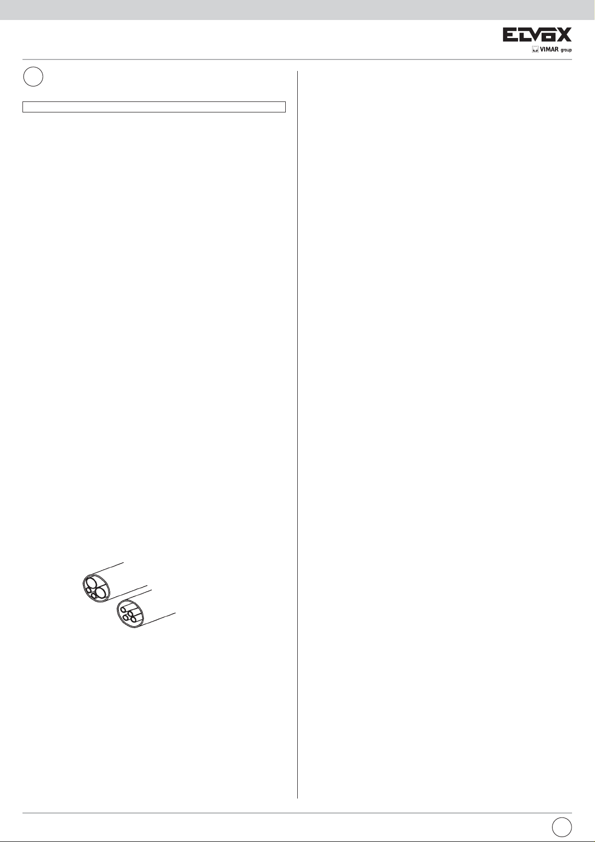
FR
Télécharger le manuel d’instructions sur le site www.vimar.com
INSTALLATION DES ALIMENTATIONS
L’alimentation devra être placée dans un endroit sec, à l’abri de la poussière
et loin de toute source de chaleur. Afin de faciliter les contrôles et les mises au
point, choisir un endroit facilement accessible. Fixer l’alimentation sur le mur à
l’aide des chevilles fournies de série ou en l’insérant dans un tableau approprié
avec barre DIN en oméga. Avant d’effectuer le raccordement, s’assurer, à l’aide
d’un testeur normal, que les conducteurs ne sont pas interrompus ou en court-circuit. Pour une plus grande sécurité de l’utilisateur, tous les appareils fonctionnent
en basse tension et sont séparés du réseau par un transformateur à haute isolation. Il convient dans tous les cas d’interposer un disjoncteur magnétothermique
d’une portée appropriée entre le réseau d’alimentation et l’appareil. Puis:
1) câbler les borniers de raccordement en suivant les schémas joints à ce ma-
nuel;
2) câbler le bornier d’alimentation situé sous la protection arrière;
3) Mettre sous tension l’alimentation; après la première phase de stabilisation
de l’installation, seules doivent rester allumées les LED ROUGES L1 et L6
indiquant la présence de tension à la plaque, aux postes et aux moniteurs.
Notez que ces recommandations s’appliquent également à tous les appareils
composant l’installation. En outre, pour les plaques avec caméra et pour les
caméras externes, il faut tenir compte des exigences suivantes:
4) La caméra fonctionne de -5°C à +50°C; pour éviter la surchauffe de l’appa-
reil, il convient de la protéger des rayons du soleil par un auvent ou autres
protections similaires.
5) L’objectif ne doit pas être exposé directement à des rayons de lumière (soleil,
phares de voiture, etc...).
6) Le sujet à filmer doit être éclairé de face; dans le cas d’éclairage insuffisant,
utilisez une lampe supplémentaire externe alimentée directement du réseau.
CONSIGNES GENERALES D’INSTALLATION ET DE POSE DES CABLES
Pour monter correctement une installation DIGIBUS, on doit tenir compte de
deux facteurs:
- le type de site où l’installation est effectuée;
- l’extension de l’installation
Tous les appareils sont réalisés aux normes “CE” selon la directive 2004/108/CE
et suivantes concernant les normes européennes de sécurité et les normes européennes pour la compatibilité électromagnétique. Malgré cela, pour que l’installation soit réalisée selon les règles de l’art, on doit tenir compte des quelques
indications qui suivent:
- les conducteurs de l’installation doivent être posés en tenant compte de la
longueur globale de l’installation et plus précisément, pour des installations
plus longues, on doit employer des câbles d’une section appropriée (faire
référence aux tableaux de cette page);
- ne pas faire passer les câbles entre le poste externe et l’alimentation et entre
cette dernière et les appareils internes conjointement à des lignes de puissance (230V ou supérieures); les faire passer dans des conduits séparés.
Conduit câbles énergie
Conduit câbles DIGIBUS
CARACTÉRISTIQUES TECHNIQUES DE L’ALIMENTATION ART.6948
Alimentation de base pour toutes les installations de portier vidéo DIGIBUS avec
boîtier en technopolimère classe V-0 elle est prédisposée pour un montage sur
tableaux avec barre DIN à oméga, avec un encombrement de douze modules, ou
bien avec fixation murale par chevilles. Cette alimentation est réalisée avec des
cartes interchangeables et des borniers extractibles pour assurer un entretien
rapide. L’alimentation dispose d’un générateur d’appel sonore et d’une rangée
de 6 LED pour la signalisation de l’état de fonctionnement.
Spécifications de l’alimentation:
- Dimensions: 208 x 135 x 72
- Poids seule alimentation: 1,5 Kg
- Alimentation: 230 V c.a. (+6/-10%) 50 - 60 Hz (autres tensions d’alimentation
sur demande)
- Puissance maximale absorbée: 60 VA.
- Alimentation partie électronique: 13,5V cc. 0,5A cycle intermittent (90 sec. ON,
420 sec. OFF). 0,5A cycle continu (maximum 10 distributeurs Art.949B et une
plaque avec caméra ou bien 60 appareils de type Art.887B, 6204, 6344, 6554,
6624, 6614 et une plaque avec caméra)
- Alimentation moniteurs: 18V cc. 0,8A cycle intermittent (90 sec. ON, 420 sc.
OFF). (maximum deux moniteurs en parallèle).
- Sortie pour gâche: 15 V rectifiés 1 A. cycle intermittent (30 sec. ON, 480 sc.
OFF).
- Sorties pour l’activation de fonctions supplémentaires: 12Vc.c. 0,15A cycle
intermittent (255 sec. ON, 255 sc. OFF). (maximum 1 relais de type 0170/001,
etc.)
Protections insérées dans l’alimentateur:
- Enroulement primaire transformateur: PTC SIEMENS type C840.
- 1er enroulement secondaire du transformateur pour alimentation électronique
interne: fusible 3,15 AL 250 V (F1).
- 2ème enroulement secondaire du transformateur pour la commande de la
gâche électrique et/ou des lampes: PTC SIEMENS type C945
- Genérateur appel électronique: PTC SIEMENS type C945
- Protection électronique contre les surcharges ou les courts-circuits sur le montant moniteur.
Contrôles visuels par une rangée de LED:
L1- Alimentation moniteur (bornes + et -) LED ROUGE
L2- Commande gâche électrique (borne S) LED JAUNE
L3- Fonction auxiliaire 1 (borne F1) LED VERT
L4- Fonction auxiliaire 2 (borne F2) LED JAUNE
L5- Phonie et bouton d’appel (3) LED VERT
L6- Alimentation du circuit digital (4 et 5) LED ROUGE
Bornes de l’alimentation et description de fonctionnement:
M1-M2:Bornes traversantes de fixation pour l’enveloppe du câble coaxial
V1-V2: Bornes traversantes de fixation pour l’âme du câble coaxial
+I: Circuit de commande d’extinction du moniteur
La borne est utilisée par les plaques ou par le standard pour éteindre
le moniteur avant un nouvel appel et à la fin de la conversation. En
court-circuitant la borne +I sur la borne 4, la tension entre les bornes +
et - chute à zéro volt et reste nulle pendant toute la durée de court-circuit
de la borne +I. Le manque de tension sur les bornes + et - est signalée
par l’extinction de la LED L1.
CH: Circuit de commande de l’activation de l’appel sonore.
La borne est utilisée par les plaques ou par le standard pour activer le
générateur de notes implanté dans l’alimentation. En court-circuitant la
borne CH sur la borne 4, on active le signal d’appel, lequel sort de la
borne 3. Le signal reste actif pendant toute la durée de court-circuit de
la borne CH.
S: Circuit de commande de la gâche électrique.
La borne est utilisée par les plaques ou par le standard pour l’ouver-
ture de la gâche électrique associée à la plaque ou au standard. En
court-circuitant la borne S sur la borne 4, on court-circuite la borne S1
sur la borne 0 (relative aux 15 V rectifiés) et la LED L2 s’allume. La borne
S1 reste en court-circuit pendant toute la durée d’activation de la borne
S.
F1: Circuit de commande d’activation de la 1re fonction auxiliaire.
La borne est utilisée par les plaques ou par le standard pour signaler l’ac-
tivation de la fonction F1. En court-circuitant la borne F1 sur la borne 4,
la tension à la borne R1 monte à 12 Vcc et cette tension reste appliquée
pendant toute la durée de court-circuit de la borne F1. L’activation de la
fonction est signalée par l’allumage de la LED L3.
12
FR
Page 13
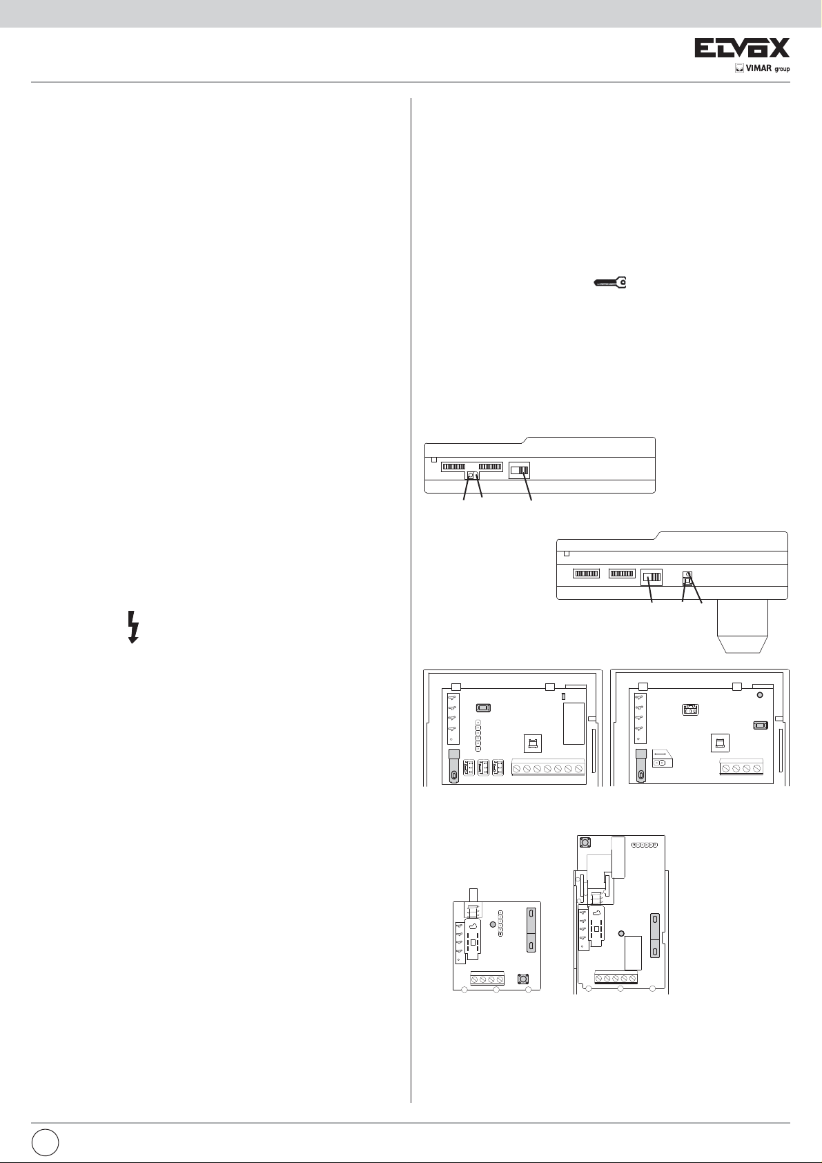
F2: Circuit de commande d’activation de la 2e fonction auxiliaire.
La borne est utilisée par les plaques ou par le standard pour signaler
l’activation de la fonction F2. En court-circuitant la borne F2 sur la borne
4, la tension à la borne R2 monte à 12 Vcc et cette tension reste appliquée pendant toute la durée de court-circuit de la borne F2. L’activation
de la fonction est signalée par l’allumage de la LED L4.
3: Circuit d’appel et phonie.
La borne est utilisée pour transmettre le signal d’appel le long de la
colonne montante et pour signaler la présence d’appareils insérés avec
combiné décroché. Au moment de l’activation de la borne CH, le signal
modulé d’appel sort de la borne 3 et la LED L5 s’allume. Dans le cas de
borne CH inactive, le circuit de la borne 3 signale la présence d’un ou
de plusieurs postes d’appartement (moniteurs) insérés avec combiné
décroché à travers l’allumage de la LED L5.
4: Circuit du <<moins>> pour l’alimentation du circuit digital.
5: Circuit +13,5 Vcc 0,5A pour l’alimentation intermittent 0,5A pour
l’alimentation continu.
La présence de tension à la borne 5 est signalée par l’allumage de la
LED L6.
-: Circuit du <<moins>> pour l’alimentation du moniteur.
+: Circuit du +18 Vcc 0,8 A pour l’alimentation du moniteur.
La présence de tension à la borne + est signalée par l’allumage de la
LED L1.
4: Circuit négatif pour les fonctions auxiliaires.
R1: Circuit +12 Vcc 0,15 A pour la fonction auxiliaire 1.
La borne est utilisée pour activer un relais avec l’activation de la fonction
F1. Quand la borne F1 est activée, une tension de 12 Vcc est présente
à la borne R1.
4: Circuit négatif pour les fonctions auxiliaires.
R2: Circuit +12 Vcc 0,15 A pour la fonction auxiliaire 2.
La borne est utilisée pour activer un relais avec l’activation de la fonction
F2. Quand la borne F2 est activée, une tension de 12 Vcc est présente
à la borne R2.
S1: Circuit pour l’actionnement de la gâche électrique 1 A.
Quand la borne S est activée, la borne S1 est court-circuitée sur la borne
0.
Le circuit est protégé par une PTC SIEMENS C945.
15 - 0: Circuit 15 V rectifiés et 1 A
Bornes pour l’alimentation de la gâche électrique et des services.
Le circuit est protégé par une PTC SIEMENS C945.
PRIM: Bornes d’alimentation: 230 Vca +6/-10% 50-60 Hz.
Ces bornes sont situées sous la protection en thermoplastique marquée
PROGRAMMATION DU NUMÉRO USAGER POUR POSTES D’APPARTEMENT, MONITEURS ET DISTRIBUTEURS DIGITAUX
Si le système prévoit le raccordement de plaques en parallèle, seulement pour
la phase de programmation du numéro usager, il convient de débrancher les
plaques qui ont le pontage ON-OFF coupé (ou en position OFF). L’utilisation des
plaques Art. 8843, 8845, 8844, 8847, 8943, 8945, 943/..., 945/5.. pour la programmation des postes d’appartement ou des moniteurs n’est possible qu’après
avoir programmé chaque touche de la plaque. Effectuez la programmation des
appareils un à la fois.
Programmation des postes d’appartement et des moniteurs par codage
interne Art. 887B, 887B/1, 6204, 62K4, 6304, 6504 par l’intermédiaire de la
plaque
1) Enfoncez pendant un instant le poussoir de programmation situé sur le
poste d’appartement ou sur le moniteur.
2) Appuyez ensuite sur la touche
à proximité du poussoir de programmation.
3) Si la LED ne s’allume pas, répétez l’opération à partir du point 1.
4) Décrocher le combiné téléphonique, vérifiez le raccordement audio avec la
plaque.
5) Composez sur la plaque le numéro de programmation de l’appareil et lancez l’appel au moyen de la touche “C”.
6) Attendre l’éxtinction de la LED sur le poste d’appartement comme confirmation de la programmation.
7) Continuez la programmation des autres appareils à partir du point 1.
jusqu’à allumage de la LED située
Partie inférieure du moniteur Art. 6304 - 6324
B
A
D
Partie inférieure du moniteur Art. 6504
A
B
D
du symbole
borne de mise à la terre n’est pas présente du fait que l’alimentation est
construite en classe 2.
OPÉRATIONS PRÉLIMINAIRES
Après l’installation et le raccordement de tous les appareils, mettre sous tension
le système et vérifier la présence de tension au système par l’intermédiaire des
LED situées sur les alimentations.
Dans le cas de montage des alimentations Art.6941, 6942 et 6947, la présence
de tension est signalée par l’allumage de la seule LED rouge L6, tandis que pour
les alimentations Art.948, on aura l’allumage des LED rouges L1 et L6. Avant
d’effectuer la programmation sur les appareils, attendez au moins une dizaine
de secondes après la mise sous tension du système.
Ensuite, vérifier et éventuellement programmer les paramètres de fonctionnement des plaques et/ou du standard.
Notez qu’un paramétrage de base a déjà été effectué en usine pour la plaque et
le standard. Ce paramétrage pouvant toutefois être adapté à vos besoins précis.
Pour la programmation des plaques et du standard, référez-vous aux notices
accompagnant les appareils. Après avoir entré les paramètres de fonctionnement de la plaque et du standard, effectuez la programmation du numéro usager
des postes d’appartement et des moniteurs. Si le système est prévu pour un
ensemble collectif d’habitations, il convient d’effectuer la programmation du numéro usager par l’intermédiaire des plaques au pied de l’escalier (secondaires).
et sont utilisées pour le raccordement au secteur. La
B
C
A
F
C
Art. 6204
Art. 62K4
B
Art. 887B/1
D
D
C
C
A
B
A- voyant interne d’indication état programmation/activation phonique
B- Bouton reset/programmation
C- Bouton gâche
D- Sélecteur à 4 positions (uniquement sur Art. 887B et 887B/1)
F- Cavalier volume sonnerie haut/bas (uniquement sur Art. 62K4)
A
Art. 887B
A
B
FR
13
Page 14
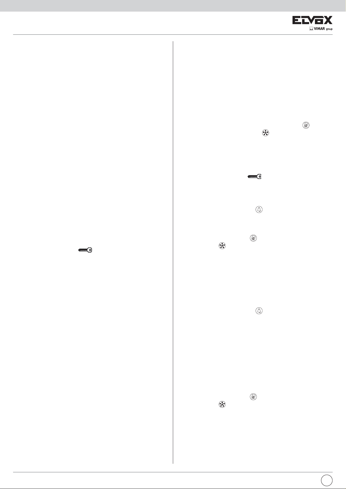
REMARQUES DE FONCTIONNEMENT ET PROGRAMMATION DES POSTES
D’APPARTEMENT ART. 62K4 ET ART. 887B/1
Signal d’appel
Les postes d’appartement Art. 62K4 et Art. 887B/1 dans la version de base ont le
signal d’appel sur le haut-parleur du poste d’appartement ; lorsque l’on décroche
le combiné de son logement, le signal d’appel s’interrompt.
Procédure de programmation paramètres d’appel (seulement pour l’Art.
887B/1)
Le poste d’appartement génère internement le signal d’appel et la relative durée:
la pression simultanée des boutons-poussoirs du poste d’appartement pour un
certain temps permet d’accéder au menu de programmation des paramètres d’appel (fréquence audio: haute, moyenne basse ; durée du signal : brève, moyenne,
prolongée).
Pour accéder au menu de programmation paramètres d’appel :
a) fréquence haute et durée brève,
b) fréquence haute et durée moyenne,
c) fréquence haute et durée prolongée ;
d) fréquence moyenne et durée brève,
e) fréquence moyenne et durée moyenne,
f) fréquence moyenne et durée prolongée ;
g) fréquence basse et durée brève,
h) fréquence basse durée moyenne,
i) fréquence basse et durée prolongée ;
Option réglage volume sonnerie (uniquement pour poste d’appartement
62K4)
Le poste d’appartement Art. 62K4 permet également de programmer deux niveaux
différents de volume de la sonnerie d’appel ; en agissant sur le cavalier “CN6 VOL” (référence “F” de la figure), on modifie le volume dans les deux modalités
suivantes :
- cavalier inséré = volume de sonnerie haut
- cavalier désinséré = volume de sonnerie bas
Procédure de programmation des paramètres d’appel pour le poste d’appartement 62K4
1) Appuyer pendant un moment sur le bouton de programmation présent sur le
poste d’appartement.
2) Appuyer ensuite sur la touche
maintenant la touche appuyée pendant 5 autres secondes, afin que le voyant
rouge passe de fixe à clignotant.
3) Si le voyant rouge ne se met à pas clignoter, répéter l’opération depuis le point
1.
4) Le poste d’appartement commence à reproduire la mélodie programmée. En
appuyant plusieurs fois sur la touche gâche “C”, on peut sélectionner en séquence 9 mélodies différentes de type et durée.
5) Après avoir choisi la mélodie désirée, il suffit d’attendre l’extinction du voyant
rouge sur le poste d’appartement en confirmation de la programmation effectuée.
Procédure de programmation des paramètres d’appel pour le poste d’appartement 887B/1
Pour accéder au menu de programmation des paramètres d’appel :
1) appuyer simultanément pendant 5 secondes environ sur les deux touches du
poste d’appartement : ce dernier activera le premier appel (fréquence élevée
et brève durée) ;
2) la pression répétée de la touche relative à la fonction auxiliaire F1 (2ème
touche) permettra de créer différentes typologies d’appel (en fréquence et
durée).
3) la pression de la touche relative à la fonction gâche (1ère touche) permettra de
confirmer et d’enregistrer le choix effectué du type d’appel ;
4) si les touches ne sont pas appuyées pendant au moins 20 secondes, le poste
d’appartement quitte la programmation des paramètres d’appel et retourne
dans son état normal de fonctionnement.
Programmation des distributeurs digitaux Art.949B par l’intermédiaire de la
plaque
1) Enfoncez pendant un instant le poussoir PS1 situé sur le distributeur digital.
2) Appuyez ensuite sur le poussoir PS2, situé sur le distributeur, jusqu’à l’allu-
mage de la première des quatre LED présentes sur le distributeur.
3) Si la LED ne s’allume pas, répétez l’opération à partir du point 1.
4) Décrochez le combiné de le poste d’appartement ou du moniteur reliés à la
borne A1 et A3 du distributeur concerné, vérifiez ensuite le raccordement
audio avec la plaque.
5) Composez sur la plaque ou sur le standard le numéro de programmation de
l’appareil et provoquez l’appel au moyen de la touche “C”.
6) Attendre l’éxtinction de la LED sur le poste d’appartement comme confirma-
tion de la programmation.
7) Pour continuer la programmation des 3 autres postes intercommuniquants
(postes d’appartement ou moniteurs) reliés au distributeur en question, réap-
jusqu’à l’allumage du voyant rouge, en
puyez sur le poussoir PS1 puis maintenez enfoncé le poussoir PS2 jusqu’à
l’allumage de la deuxième ou troisième ou encore de la quatrième LED.
8) L’allumage des LED indique le poste intercommuniquant qui est en phase de
programmation selon le tableau suivant:
LED1 ¬ ® Bornes A1 et A3
LED2 ¬ ® Bornes B1 et B3
LED3 ¬ ® Bornes C1 et C3
LED4 ¬ ® Bornes D1 et D3
9) Continuez la programmation des appareils en répétant pour chacun d’eux les
opérations décrites à partir du point 1.
PROGRAMMATION DES POSTES D’APPARTEMENT, MONITEURS ET DISTRIBUTEURS DIGITAUX A PARTIR DU STANDARD Art.945B E et Art.955
La programmation du numéro à associer aux postes d’appartement ou aux moniteurs, en utilisant le standard, s’effectue de la manière suivante:
- Positionner le standard dans le mode « INTERNE ».
- Décrochez le combiné du standard et appuyez sur la touche
à allumer le témoin associé à la touche
- Sans raccrocher le combiné du standard, effectuez la programmation de le
poste d’appartement ou du moniteur ou bien du distributeur:
Programmation des postes d’appartement et des moniteurs par codage interne Art. 887B, 6204, 6304, 6324, 6504
1) Enfoncez pendant un instant le poussoir de programmation situé sur le poste
d’appartement ou sur le moniteur (voir figures ci-dessous).
2) Appuyez ensuite sur la touche
proximité du poussoir de programmation.
3) Si la LED ne s’allume pas, répétez l’opération à partir du point 1.
4) Décrocher le combiné téléphonique, vérifiez le raccordement audio avec le
standard.
5) Composez sur le standard le numéro de programmation de l’appareil et provo-
quez l’appel au moyen de la touche
6) Attendre l’éxtinction de la LED sur le poste d’appartement comme confirmation
de la programmation.
7) Continuez la programmation des autres appareils à partir du point 1.
N.B.: Le raccordement audio entre le standard et le poste d’appartement n’est
réalisé que si le témoin de la touche
puyez sur la touche
correspond au temps maximum de conversation présélectionné dans le standard.
Programmation des distributeurs digitaux Art.949B
1) Enfoncez pendant un instant le poussoir PS1 situé sur le distributeur digital.
2) Appuyez ensuite sur le poussoir PS2, situé sur le distributeur, jusqu’à l’allu-
mage de la première des quatre LED présentes sur le distributeur.
3) Si la LED ne s’allume pas, répétez l’opération à partir du point 1.
4) Décrochez le combiné de le poste d’appartement ou du moniteur reliés à la
borne A1 et A3 du distributeur concerné, vérifiez ensuite le raccordement audio
avec le standard.
5) Composez sur le standard le numéro de programmation de l’appareil et provo-
quez l’appel au moyen de la touche
6) Attendre l’éxtinction de la LED sur le poste d’appartement comme confirmation
de la programmation.
7) Pour continuer la programmation des autres 3 postes intercommuniquants
(postes d’appartement ou moniteurs) reliés au distributeur en question, réappuyez sur le poussoir PS1 puis maintenez enfoncé le poussoir PS2 jusqu’à
l’allumage de la deuxième ou troisième ou encore de la quatrième LED.
8) L’allumage des LED indique le poste intercommuniquant qui est en phase de
programmation selon le tableau suivant:
LED1 ¬ ® Bornes A1 et A3
LED2 ¬ ® Bornes B1 et B3
LED3 ¬ ® Bornes C1 et C3
LED4 ¬ ® Bornes D1 et D3
9) Continuez la programmation des appareils en répétant pour chacun d’eux les
opérations décrites à partir du point 1.
N.B.: Le raccordement audio entre le standard et le poste d’appartement n’est
réalisé que si le témoin de la touche
puyez sur la touche
correspond au temps maximum de conversation présélectionné dans le standard.
pour allumer le témoin. Le temps d’allumage du témoin
pour allumer le témoin. Le temps d’allumage du témoin
.
jusqu’à allumage de la LED située à
.
est allumé; dans le cas contraire, réap-
.
est allumé; dans le cas contraire, réap-
de manière
14
FR
Page 15
FONCTIONNEMENT DE L’INSTALLATION
Les portiers vidéo de la série DIGIBUS comporte une alimentation de base
Art.6948.
Cette solution permet d’alimenter les moniteurs, les postes d’appartement, les
distributeurs digitaux, les plaques et le standard.
Dans le cas où l’installation l’exigerait, pour des motifs de longueur de circuit ou
de quantité d’appareils ou bien de chute de tension, il est possible d’utiliser les
alimentations supplémentaires suivantes: Art.6942 pour alimenter les plaques, le
standard, les distributeurs digitaux, les postes d’appartement et les moniteurs
(pour le circuit digital); Art.6947 pour alimenter les moniteurs et pour regénérer le
signal d’appel. Pour la disposition des alimentations, référez-vous aux schémas
relatifs à l’installation. Les appels à partir de la plaque ou du standard vers les
appareils, postes d’appartement ou moniteurs, s’effectuent en composant d’abord
sur le clavier de la plaque ou du standard le numéro du correspondant interne
puis en appuyant sur la touche C ou bien sur la touche
appels, appuyez sur la touche R.
Une fois enfoncée le bouton d’appel, la plaque ou le standard transmettra le
code numérique qui permettra de mettre en communication l’interne. Ensuite, la
première plaque ou le premier standard, relié à la colonne montante des moniteurs (ou des postes d’appartement), couperont momentanément l’alimentation
aux bornes + et - de la colonne montante, de manière à éteindre les moniteurs
éventuellement allumés, activeront le générateur d’appel de l’alimentation pour
la durée du temps d’appel sélectionné sur ceux-ci, et transféreront le signal d’appel vers la colonne montante. Au terme de l’appel, le poste d’appartement ou le
moniteur se relieront en mode audio avec la plaque de rue ou bien avec le standard. Dans le cas de moniteur et de plaque avec caméra ou bien de moniteur et
de standard avec caméra, sur les moniteurs apparaîtra respectivement l’image
filmée par la caméra de la plaque ou par la caméra du standard.
Une fois enclenché le poste d’appartement ou le moniteur, on pourra à partir de
ceux-ci: effectuer l’ouverture de la gâche électrique au moyen de la touche
.
Les fonctions complémentaires pourront être activées indépendamment si l’interne est en communication ou non; toutefois, la touche
ture de la gâche électrique de la plaque uniquement si l’interne est relié avec la
plaque de rue, sinon il effectuera l’appel au standard conciergerie. Après l’appel,
la liaison entre les postes restera active pendant toute la durée du temps d’attente
(sélectionné sur la plaque ou sur le standard), si le combiné n’est pas décroché
ou bien pour toute la durée du temps de conversation si les postes communiquent
entre eux. Si vous raccrochez le combiné avant que le temps de conversation soit
écoulé, le portier ou le moniteur se désactiveront après environ 5 s.
DESCRIPTION DES INSTALLATIONS-TYPE:
Nous décrivons ci-après trois installations de portiers vidéo DIGIBUS qui utilisent
l’alimentation Art.6948.
Dans le cas d’utilisation des deux fonctions auxiliaires, il faut prévoir le raccordement des bornes F1 ou F2 de la plaque (ou du standard) avec les bornes respectives de l’alimentation. L’utilisation des deux fonctions auxiliaires avec les postes
d’appartement et les moniteurs Art.8877, 6201, 6327nécessite le raccordement
des fonctions entre le poste/moniteur et le distributeur digital Art.949B.
A) Installation type portier vidéo avec plaque avec caméra (voir dessin SI212).
B) Installation type portier vidéo pour ensemble collectif d’habitations avec plaque
principale avec caméra et plaques secondaires vidéo/audio (voir dessin
si177).
C) Installation type portier vidéo avec plaque avec caméra et standard concier-
gerie comportant un moniteur et une caméra (voir dessin si176).
A) Installation type portier vidéo avec plaque avec caméra (schéma SI212).
- Frappe au clavier de la plaque du numéro usager, 77 par exemple.
- Pression sur la touche C.
- Activation de la borne +L de la plaque.
- Envoi sur la ligne 1 du code numérique afférent au numéro 77 vers la colonne
montante moniteur.
- Activation de courte durée de la borne +I et extinction des moniteurs éventuellement allumés.
- Raccordement du circuit audio du moniteur avec le code 77 à la colonne
montante.
- Activation de la borne CH de la plaque pour la durée du temps d’appel et
transfert du signal d’appel vers la ligne 3 de la colonne montante.
- Raccordement du circuit audio de la plaque après le temps d’appel.
- Si le combiné du moniteur n’est pas décroché, la plaque compte le temps
d’attente.
- Si le combiné du moniteur est décroché avant que le temps d’attente soit
écoulé, la plaque commence à compter le temps de conversation maximum.
- Avec combiné raccroché ou décroché, il est possible d’activer les deux fonctions complémentaires et l’ouverture de la gâche électrique. Notez que les
deux fonctions complémentaires peuvent être activées même si le moniteur
n’a pas été appelé.
- Si la touche
tante le code d’ouverture de la gâche électrique avec son numéro respectif
(77); la plaque d’où a été effectué l’appel, une fois le code reconnu, activera
donc la borne S pour la durée du temps de gâche électrique, affecté à celle-ci.
est enfoncée, le moniteur enverra vers la colonne mon-
. Pour annuler les
permet l’ouver-
En conséquence, la borne S1 de l’alimentation chutera à zéro volt pour la
durée du temps d’activation de la borne S.
- Si la touche
le code de la fonction complémentaire F2 avec son numéro respectif (77); la
plaque, après avoir reconnu le code, activera donc la borne F2 pour la durée
du temps F2.
- Si la touche
tante le code de la fonction complémentaire F1 avec son numéro respectif
(77); la plaque, après avoir reconnu le code, activera donc la borne F1 pour
la durée du temps F1.
- Une fois le temps d’attente ou de conversation écoulé, la plaque reliée au
moniteur enverra un code de remise à zéro pour désactiver le moniteur et par
conséquent activera la borne +I pour éteindre le moniteur.
- Il en est de même au raccrochage du combiné du moniteur avant que le
temps de conversation soit écoulé; environ 5 s après le raccrochage du combiné, la plaque envoie un code de remise à zéro et active la borne +I.
B) Installation type portier vidéo pour ensemble collectif d’habitations
avec plaque principale avec caméra et plaques secondaires vidéo/audio
(schéma SI177).
- Frappe au clavier de la plaque principale du numéro usager, par exemple 77.
- Pression sur la touche C.
- Activation de la borne +L de la plaque principale.
- Envoi sur la ligne 1 du code numérique afférent au numéro 77 vers la colonne
montante.
- Reconnaissance du code numérique d’appel, afférent au numéro 77, par
toutes les plaques secondaires. Si le code d’appel (77) est compris entre le
numéro minimum et le numéro maximum d’une des plaques secondaires, la
plaque respective aura le comportement suivant.
- Positionnement de la plaque secondaire dans l’état “OCCUPÉ-ATTENDEZ”.
- Activation temporaire de la borne +I de la plaque secondaire et extinction des
moniteurs éventuellement allumés.
- Regénération et répétition du code d’appel associé au numéro 77 vers la
colonne montante moniteur.
- Raccordement du circuit audio du moniteur avec le code 77 vers la colonne
montante.
- Activation de la borne CH de la plaque secondaire pour la durée du temps
d’appel, présélectionné sur la plaque secondaire et transfert du signal d’appel
vers la ligne 3 de la colonne montante.
- Raccordement du circuit audio de la plaque principale après le temps d’appel,
présélectionné sur la plaque principale.
- Si le combiné du moniteur n’est pas décroché, la plaque principale compte le
temps d’attente.
- Si le combiné du moniteur est décroché avant que le temps d’attente soit
écoulé, la plaque principale commencer à compter le temps de conversation
maximum.
- Avec combiné raccroché ou décroché, il est possible d’activer les deux fonctions complémentaires et l’ouverture de la gâche électrique. Notez que les
deux fonctions complémentaires peuvent être activées même si le moniteur
n’a pas été appelé.
- Si la touche
d’ouverture de la gâche électrique avec son numéro respectif (77); la plaque
principale d’où a été effectué l’appel, une fois le code reconnu, activera donc
la borne S pour la durée du temps de gâche électrique, affecté à celle-ci. En
conséquence, la borne S1 de l’alimentation chutera à zéro volt pour la durée
du temps d’activation de la borne S.
- Si la plaque secondaire, qui a reproduit l’appel, a le paramètre de validation
gâche électrique ajusté à 0001, celle-ci activera aussi sa borne S au moment
de la pression sur la touche
- Si la touche
le code de la fonction complémentaire F2 avec son numéro respectif (77); la
plaque secondaire et la plaque principale, après avoir reconnu le code, activeront leurs bornes respectives F2 pour la durée du temps F2.
- Si la touche
le code de la fonction complémentaire F1 avec son numéro respectif (77); la
plaque secondaire et la plaque principale, après avoir reconnu le code, activeront leurs bornes respectives F1 pour la durée du temps F1.
- Une fois le temps d’attente ou de conversation écoulé, la plaque principale
reliée au moniteur enverra un code de remise à zéro pour désactiver le moniteur. En conséquence, la plaque secondaire activera la borne +I pour éteindre
le moniteur et quittera l’état “OCCUPÉ-ATTENDEZ”.
- Il en est de même au raccrochage du combiné du moniteur avant que le
temps de conversation soit écoulé; environ 5 s après le raccrochage du combiné, la plaque principale enverra un code de remise à zéro et la plaque
secondaire activera la borne +I.
- En même temps que la plaque principale est en conversation avec un moniteur, il est possible d’appeler les moniteurs ou les postes d’appartement à
partir des autres plaques secondaires qui ne se trouvent pas en état “OCCUPÉ-ATTENDEZ”.
est enfoncée, le moniteur enverra vers la colonne montante
est enfoncée, le moniteur enverra vers la colonne mon-
est enfoncée, le moniteur enverra vers la plaque le code
.
est enfoncée, le moniteur enverra vers la colonne montante
est enfoncée, le moniteur enverra vers la colonne montante
FR
15
Page 16

N.B.: dans une installation pour immeubles collectifs, il faut tenir compte que
le temps d’activation de la sonnerie, de la plaque principale, doit être plus
long du temps des plaques secondaires d’au moins une seconde, afin d’éviter
le retour du signal d’appel dans l’écouteur de la plaque principale.
C) Installation type portier vidéo avec plaque avec caméra et standard
conciergerie comportant un moniteur et une caméra (schéma si176).
Avec le standard conciergerie en position EXTERNE (témoin de la touche
allumé)
- Frappe au clavier de la plaque principale du numéro usager, par exemple 77.
- Activation de la borne +L de la plaque.
- Envoi sur la ligne 1 du code numérique afférent au numéro 77 vers la colonne
montante.
- Reconnaissance du code numérique d’appel par le standard conciergerie et
activation temporaire de la borne +I pour l’extinction des moniteurs éventuellement allumés.
- Visualisation sur le standard de l’indication “STOP”.
- Activation de la borne I du standard, pour maintenir le moniteur du standard
éteint.
- Regénération et répétition du code d’appel associé au numéro 77 vers la
colonne montante moniteur.
- Raccordement du circuit audio du moniteur avec le code 77 vers la colonne
montante.
- Activation de la borne CH du standard pour la durée du temps d’appel, présélectionné sur le standard et transfert du signal d’appel vers la ligne 3 de la
colonne montante.
- Raccordement du circuit audio de la plaque après le temps d’appel, présélectionné sur la plaque.
- Si le combiné du moniteur n’est pas décroché, la plaque compte le temps
d’attente.
- Si le combiné du moniteur est décroché avant que le temps d’attente soit
écoulé, la plaque commence à compter le temps de conversation maximum.
- Avec combiné raccroché ou décroché, il est possible d’activer les deux fonctions complémentaires et l’ouverture de la gâche électrique. Notez que les
deux fonctions complémentaires peuvent être activées même si le moniteur
n’a pas été appelé.
- Si la touche est enfoncée, le moniteur enverra vers la colonne montante le code d’ouverture de la gâche électrique avec son numéro respectif
(77); la plaque d’où a été effectué l’appel, une fois le code reconnu, activera
donc la borne S pour la durée du temps de gâche électrique, présélectionnée
sur celle-ci. En conséquence, la borne S1 de l’alimentation chutera à zéro volt
pour la durée du temps d’activation de la borne S.
- Si le standard a le paramètre de validation gâche électrique ajusté à 0001,
celui-ci activera aussi sa borne S au moment de la pression sur la touche
du moniteur.
- Si la touche
le code de la fonction complémentaire F2 avec son numéro respectif (77); le
standard et la plaque, après avoir reconnu le code, activeront leurs bornes
respectives F2 pour la durée du temps F2.
- Si la touche
le code de la fonction complémentaire F1 avec son numéro respectif (77); le
standard et la plaque, après avoir reconnu le code, activeront leurs bornes
respectives F1 pour la durée du temps F1.
- Une fois le temps d’attente ou de conversation écoulé, la plaque principale
reliée au moniteur enverra un code de remise à zéro pour désactiver le moniteur. En conséquence, le standard activera la borne +I pour éteindre le moniteur et effacer l’indication “STOP”.
- Il en est de même au raccrochage du combiné du moniteur avant que le temps
de conversation soit écoulé; environ 5 s après le raccrochage du combiné, la
plaque enverra un code de remise à zéro et le standard activera la borne +I.
Avec le standard conciergerie en position INTERNE (témoin de la touche
éteint)
- Frappe au clavier de la plaque principale du numéro usager, par exemple 77.
- Pression sur la touche C.
- Activation de la borne +L de la plaque.
- Envoi sur la ligne 1 du code numérique afférent au numéro 77 vers la colonne
montante.
- Visualisation du numéro 77 sur l’afficheur de droit du standard et activation du
signal sonore d’appel.
- Si la borne I du standard est active, désactivation de la borne.
- Allumage du moniteur du standard avec visualisation de l’image filmée par la
caméra de la plaque.
- Raccordement du circuit audio du standard avec la plaque.
- Si le combiné du standard n’est pas décroché, la plaque compte le temps
d’attente.
- Si le combiné du standard est décroché avant que le temps d’attente soit
écoulé, la plaque commencer à compter le temps de conversation maximum.
- Si la touche
est enfoncée, le moniteur enverra vers la colonne montante
est enfoncée, le moniteur enverra vers la colonne montante
est enfoncée, le standard enverra le code de la fonction
complémentaire; la plaque, après avoir reconnu le code, activa la borne F2
pour la durée du temps F2.
- Une fois le temps d’attente ou de conversation écoulé, la plaque principale
reliée au moniteur enverra un code de remise à zéro pour déclencher le standard. En conséquence, le standard activera la borne +I pour éteindre le moniteur.
- Il en est de même au raccrochage du combiné du moniteur avant que le temps
de conversation soit écoulé; environ 5 s après le raccrochage du combiné, la
plaque enverra un code de remise à zéro et le standard activera la borne +I.
Avec le standard conciergerie en position INTERNE et appel à partir du moniteur
(ou poste d’appartement):
- Avec le moniteur désactivé (éteint), pression sur la touche
- Envoi sur la ligne 1 du code numérique afférent à l’appel conciergerie avec le
numéro du moniteur, 77 par exemple.
- Visualisation du numéro 77 sur l’afficheur de gauche du standard et activation
du signal sonore d’appel.
- Si la standardiste veut appeler le moniteur d’où a été effectué l’appel, elle
devra effectuer les opérations suivantes:
- Transfert du numéro 77 sur l’afficheur à l’aide de la touche
- Pression sur la touche marquée
- Envoi sur la ligne 1 du code numérique afférent au numéro 77 vers la colonne
montante.
- Activation temporaire de la borne T du standard, pour l’allumage de la caméra.
- Si la borne +I du standard est active, désactivation de la borne.
- Activation temporaire de la borne +I et extinction des moniteurs éventuellement allumés.
- Raccordement du circuit audio du moniteur avec le code 77 vers la colonne
montante.
- Activation de la borne CH du standard pour la durée du temps d’appel, et
transfert du signal d’appel vers la ligne 3 de la colonne montante.
- Raccordement du circuit audio du standard après le temps d’appel.
- Si le combiné du moniteur n’est pas décroché, le standard compte le temps
d’attente.
- Si le combiné du moniteur est décroché avant que le temps d’attente soit
écoulé, le standard commence à compter le temps de conversation maximum.
- Avec combiné raccroché ou décroché, il est possible d’activer les deux
fonctions complémentaires. Notez que les deux fonctions complémentaires
peuvent être activées même si le moniteur n’a pas été appelé.
- Une fois le temps d’attente ou de conversation écoulé, le standard relié au
moniteur enverra un code de remise à zéro pour désactiver le moniteur, activera la borne +I pour éteindre le moniteur de la colonne montante, activera la
borne I pour éteindre son moniteur et désactivera la borne T pour éteindre sa
caméra.
- Il en est de même au raccrochage du combiné du moniteur avant que le temps
de conversation soit écoulé; environ 5 s après le raccrochage du combiné, le
standard enverra un code de remise à zéro et activera les bornes respectives.
N.B.: dans une installation avec plaque principale et standard, il faut tenir
compte que le temps d’activation de la sonnerie, de la plaque principale,
doit être plus long du temps du standard d’au moins une seconde, afin
d’éviter le retour du signal d’appel dans l’écouteur de la plaque principale.
.
.
16
FR
Page 17

DE
Die Bedienungsanleitung ist auf der Website www.vimar.com zum
Download verfügbar
INSTALLATION DER NETZGERÄTE
Das Netzgerät ist an einem trockenen und staubfreien Ort unter Vermeidung der
Nähe von Wärmequellen zu installieren. Zur Erleichterung von Kontrollen und
Einstellungen sollte der Aufstellungsort gut zugänglich sein. Das Netzgerät mit
den beigepackten Dübeln an der Wand befestigen oder in einen Verteiler mit
DIN-Omegaschiene einsetzen. Vor dem Anschluß an das Stromnetz mit einem
Testgerät sicherstellen, daß die Leiter nicht unterbrochen oder kurzgeschlossen
sind. Zur größeren Sicherheit des Anwenders werden alle Apparate mit Niederspannung betrieben und durch einen stark isolierenden Transformator vom
Stromnetz getrennt. In jedem Fall sollte jedoch zwischen dem Stromnetz und
der Anlage ein Fehlerstromschutzschalter von angemessener Stromfestigkeit
installiert werden. Um die Installation zu beenden, folgendermaßen vorgehen:
1) Die Anschlußklemmenleisten unter Beachtung der diesem Handbuch beiliegenden Pläne verkabeln.
2) Die Versorgungsklemmenleiste unterhalb der Abdeckung an der Rückseite
anschließen.
3) Netzgerätversorgung einschalten: Nach einer ersten Einrichtphase der Anlage dürfen lediglich die ROTEN LED L1-L6 für die Anzeige der Versorgungsspannung des Klingeltableaus, der Sprechgeräte und der Monitoren
aufleuchten. Diese Hinweise gelten ebenso für alle anderen Apparate dieser
Anlage. Darüber hinaus ist bei Klingeltableaus mit Kamera und bei Außenkameras folgendes zu beachten:
4) Betrieb bei Temperaturen zwischen -5° und +50°C. Um die Anlage vor Überhitzung, z.B. vor starker Sonneneinstrahlung zu schützen, empfiehlt sich die
Montage einer Sonnenblende oder anderer Wetterschutzvorrichtungen.
5) Das Objektiv ist vor direkten Lichtquellen zu schützen (Sonne, Scheinwerferlicht usw.).
6) Der Besucher muß von vorne angeleuchtet werden. Bei unzureichender
Beleuchtung ist zusätzlich eine netzversorgte Außenlampe anzubringen.
ALLGEMEINE HINWEISE FÜR INSTALLATION UND VERKABELUNG
Für die korrekte Installation einer DIGIBUS-Anlage sind folgende Faktoren zu
berücksichtigen:
- der Typ des Gebäudes, in dem die Installation erfolgt
- die Größe der Anlage
Alle Apparate sind nach den “CE“-Normen gemäß der 89/336/EWG bezüglich der europäischen Sicherheitnormen und der europäischen Normen bzgl.
der elektromagnetiscen Verträglichkeit konstruiert. Trotzdem ist im Sinne einer
einwandfreien Installation die Beachtung einiger wenigen, einfachen Hinweise
erforderlich:
- Die Leiter der Anlage sind unter Berücksichtigung der Gesamtlänge der An-
lage zu verlegen; der Querschnitt der Adern steigt mit der Gesamtlänge der
Verkabelung wie in der untenstehenden Tabelle ersichtlich.
- Die Kabel zwischen den Außenstationen/Innenstellen und dem Netzgerät
dürfen nicht gemeinsam mit den Stromleitungen (230V oder mehr) verlegt
werden, sondern sind in getrennten Kanälen zu führen.
Stromkabelkanal
DIGIBUS-Kabelkanal
Technische Merkmale des Netzgerätes Art. 6948
Basis-Netzgerät für sämtliche DIGIBUS-Videotürsprechanlagen mit technopolimerem V-0-Klasse-Gehäuse und Vorrüstung für die Montage auf DIN-OmegaSchiene (12 Module) bzw. für Wandbefestigung mit Dübeln.
Das Netzgerät verfügt über auswechselbare Karten und abnehmbare Klemmenleisten für eine schnelle Wartung sowie über einen Ruftongenerator und 6 LED
für die Betriebsanzeige.
Technische Daten des Netzgerätes:
- Abmessungen: 208x135x72
- Gewicht (nur Netzgerät): 1,5Kg
- Versorgung: 230V A.C. (+6/-10%) 50-60Hz (auf Anfrage auch andere erhältlich)
- maximale Leistungsaufnahme: 70VA
- Ausgang für Stromversorgung von Sprechanlagen
und Klingeltableau: 13,5VDC 0,5A aussetzender Zyklus (90 Sek. ON, 420
Sek. OFF) 0,5 A ständig (Max. 10 Verteiler Art. 949B und eine Videotürstelle
oder 60 Apparatevom Typ Art. 887B, 6204, 6344, 6554, 6624, 6614 und eine
Videotürstelle)
- Ausgang für die Monitor-Stromversorgung: 18VDC 0,8A aussetzender Zyklus
(90 Sek. ON, 420 Sek. OFF) (Max. 2 parallele Monitore vom)
- Türöffnerausgang: 15V gleichgerichtet 1A aussetzender Zyklus (30 Sek. ON,
480 Sek. OFF)
- Ausgänge für die Aktivierung von Zusatzfunktionen:12VDC 0,15A aussetzender Zyklus (255 Sek. ON, 255 Sek. OFF) (Max. 1 Relais vom Typ 0170/001
usw.)
Eingebaute Schutzvorrichtungen:
- Transformator-Primärwicklung: PTC SIEMENS Typ C840;
- 1. Sekundärwicklung für Stromversorgung des internen Schaltkreises: Sicherung F- 3,15 AL 250 V (F1);
- 2. Sekundär-Trafowicklung für die Versorgung des Türöffners und/oder der
Lampen: PTC SIEMENS Typ C945;
- elektronischer Rufgenerator: PTC SIEMENS Typ C945;
- elektronischer Schutz vor Überlast oder Kurzschluß an der Monitor-Steigleitung bzw am Klingeltableau.
LED-Kontrollanzeige:
L1 - Versorgung Monitor (Klemmen + und -) ROT LED
L2 - Türöffnerfunktion (Klemme S) GELB LED
L3 - Hilfsfunktion 1 (Klemme F1) GRÜN LED
L4 - Hilfsfunktion 2 (Klemme F2) GELB LED
L5 - Sprechleitung und Ruftongenerator (3) GRÜN LED
L6 - Versorgung digitaler Schaltkreis (4 und 5) ROT LED
Funktionsbeschreibung der Netzgerätklemmen
M1-M2: Befestigungsklemmen für Abschirmung des Koaxialkabels
V1-V2: Befestigungsklemmen für Innenleiter des Koaxialkabels
+I: Anschluß für die Funktion Monitorausschaltung
Diese Klemme der Klingeltableaus oder der Telefonzentrale dient der
Monitorausschaltung am Ende eines Gespräches und vor einem neuen
Anruf. Wenn die Klemme +I mit der Klemme 4 kurzgeschlossen wird,
fällt die Spannung zwischen den Klemmen + und – auf Null ab und
bleibt für die gesamte Kurzschlußzeit auf Null. Die LED L1 schaltet sich
bei fehlender Spannung an den Klemmen + und – aus.
CH: Anschluß Ruftonaktivierung
Diese Klemme der Klingeltableaus oder der Telefonzentrale dient der
Aktivierung des Ruftongenerators im Netzgerät. Durch Kurzschließen
von Klemme CH mit Klemme 4 wird ein Rufton ausgelöst, der von der
Klemme 3 ausgeht. Der Ton dauert solange an, wie die Klemme CH
kurzgeschlossen bleibt.
S: Anschluß Türöffnerfreigabe
Diese Klemme der Klingeltableaus oder der Telefonzentrale dient dem
Öffnen des Schlosses der entsprechenden Türstelle. Schließt man die
Klemme S mitauf der Klemme 4 kurz, so wird die Klemme S1 mit der
Klemme O (entsprechend den gleichgerichteten 15 V) kurzgeschlossen,
und die LED L2 leuchtet auf. Die Klemme S1 bleibt so lange kurzgeschlossen, wie die Klemme S aktiviert ist.
F1: Anschluß 1. Hilfsfunktion
Diese Klemme der Klingeltableaus oder der Telefonzentrale dient der
Aktivierung der Funktion F1. Durch Kurzschließen von Klemme F1 mit
Klemme 4 steigt die Spannung an Klemme R1 auf 12Vdc und bleibt solange auf 12V, wie die Klemme F1 kurzgeschlossen ist. Die Aktivierung
wird durch LED L3 angezeigt.
DE
17
Page 18

F2: Anschluß 2. Hilfsfunktion
Diese Klemme der Klingeltableaus oder der Telefonzentrale dient der
Aktivierung der Funktion F2. Durch Kurzschließen von Klemme F2 mit
Klemme 4 steigt die Spannung an Klemme R2 auf 12Vdc und bleibt solange auf 12V, wie die Klemme F2 kurzgeschlossen ist. Die Aktivierung
wird durch LED L4 angezeigt.
3: Anschluß für Ruf- und Sprechfunktion
Diese Klemme sendet Rufsignale über die Steigleitung und signalisiert
eingeschaltete Sprechgeräte mit abgenommenem Hörer. Bei Aktivierung der Klemme CH geht von der Klemme 3 ein moduliertes Rufsignal
aus und LED L5 schaltet sich ein. Wenn die Klemme CH deaktiviert ist,
signalisiert die Klemme 3 das Vorhandensein von einer oder mehreren
Sprechgeräten (Monitore) mit abgehobenem Hörer durch Aufleuchten
von LED L5.
4: Minus-Versorgung Digitalschaltkreis
5: +13,5Vdc 0,5A ständig 0,5A aussetzender Zyklus für Versor-
gung Digitalschaltkreis
Aufleuchten von LED L6 zeigt an, daß Klemme 5 unter Spannung steht.
-: Minus-Versorgung Monitor
+: +18Vdc 0,8A für Versorgung Monitor Aufleuchten von LED L1
zeigt an, daß Klemme + unter Spannung steht.
4: Minus-Versorgung für Hilfsfunktionen
R1: +12Vdc 0,15A für Hilfsfunktion 1
Die Klemme dient zur Aktivierung der Funktion F1. Wenn die Klemme F1
aktiviert ist, weist die Klemme R1 eine Spannung von 12Vdc auf.
4: Minus-Versorgung für Hilfsfunktionen
R2: +12Vdc 0,15A für Hilfsfunktion 2
Die Klemme dient zur Aktivierung der Funktion F2. Wenn die Klemme F1
aktiviert ist, weist die Klemme R2 eine Spannung von 12Vdc auf.
S1: Anschluß Türöffnerfreigabe 1A
Bei Aktivierung von Klemme S wird Klemme S1 mit Klemme 0 kurzge-
schlossen. Die Leitung ist mit der PTC SIEMENS Typ C945;
15-0: 15V gleichgerichtet
Klemmen für Versorgung der Türöffner und Verbraucher.
und 1A für Türöffnerfreigabe
Die Leitung ist mit der PTC SIEMENS Typ C945;
PRIM: Versorgungsklemmen: 230Vac +6/-10% 50-60Hz
Diese Klemmen befinden sich unter einer Schutzabdeckung aus Ther-
Programmierung der Teilnehmernummern für Sprechanlangen, Monitore
und digitale Verteiler
Wenn die Anlage einen Parallelanschluß der Klingeltableaus vorsieht, empfiehlt
es sich, die Verbindung zu den Klingeltableaus, dessen Brücke EIN/AUS stromlos oder in Position AUS ist, für die Zeit der Programmierung zu unterbrechen.
Die Benutzung der Klingeltableaus Art. 8843, 8845, 8844, 8847, 8943, 8945,
943/... und 943/5... zur Programmierung der Sprechgeräte und Monitore darf
erst nach Programmierung aller Tasten des Tableaus erfolgen. Die Apparate
einzeln programmieren.
Programmierung der Sprechgeräte und der Monitore mit interner Codierung Art. 887B, 8871/B, 6204, 62K4, 6304, 6504 vom Klingeltableau aus
1) Drücken Sie kurz den Programmierungsschalter, der sich sowohl auf der
Sprechgarnitur als auch auf den Monitoren befindet.
2) Drücken Sie dann die Taste
mierungsschalter aufleuchtet.
3) Sollte die LED nicht aufleuchten, wiederholen Sie den Vorgang ab 1).
4) Heben Sie den Hörer ab und überprüfen Sie die Audioverbindung mit dem
Klingeltableau.
5) Geben Sie auf dem Klingeltableau die Nummer ein, mit der die Sprechgarnitur programmiert werden soll und senden Sie den Ruf mit Hilfe der Taste
“C“.
6) Warten Sie für die LED-Ausschaltung beim Haustelefon als Programmierungbastätigung.
7) Gehen Sie bei der Programmierung der anderen Apparate in der gleichen
Weise vor.
, bis die rote LED neben dem Program-
Monitorunterseite Art. 6304 - 6324
B
A
D
Monitorunterseite Art. 6504
moplastmaterial mit dem Zeichen
Es gibt kein Erdungskabel, da es sich hier um ein Netzgerät der Klasse
2 handelt.
Einstellungen vor der Inbetriebnahme
Nach Installation und Anschluß der Anlage die Stromversorgung einschalten und
das Anliegen von Spannung anhand der LED auf dem Netzgerät kontrollieren.
Bei den Netzgeräten Art. 6941, 6942 und 6947 wird die Spannung durch das
Aufleuchten von nur einer LED (L6 rot) angezeigt, während bei dem Netzgerät
Art. 6948 die roten LED L1 und L6 aufleuchten. Nach dem Einschalten der Stromversorgung müssen mind. 10 s vergehen, bevor mit der Programmierung der Anlage begonnen werden kann. Anschließend müssen die Funktionsparameter der
Klingeltableaus und der Hauptstelle kontrolliert und evtl. programmiert werden.
Sowohl die Klingeltableaus als auch die Hauptstelle sind werkseitig bereits mit
einer Basisprogrammierung konfiguriert, welche je nach Anforderung der Anlage
verändert werden kann. Zur Programmierung der Klingeltableaus und der Hauptstelle siehe beiliegende Anleitungen.
Geben Sie nach Programmierung der Funktionsparameter von Klingeltableaus
und Hauptstelle die Teilnehmernummern der Sprechgeräte und der Monitore ein.
Bei Anlagen für große Gebäudekomplexe empfiehlt es sich, die Teilnehmernummern an den Klingeltableaus der Nebeneingänge zu programmieren.
und dienen dem Netzanschluß.
B
C
Art. 6204
Art. 887B/1
D
A
A
B
D
A
A
B
F
C
Art. 62K4
B
D
C
C
A
B
Art. 887B
18
A- Interne Led für die Statusanzeige Programmierung/Aktivierung Sprechleitung
B- Reset-/Programmierungstaste
C- Türöffnertaste
D- Wahlschalter mit 4 Stellungen (nur Art. 887B und 887B/1)
F - Jumper Ruftonlautstärke hoch/niedrig (nur Art. 62K4)
DE
Page 19

HINWEISE ZU BETRIEB UND PROGRAMMIERUNG DER HAUSTELEFONE
ART. 62K4 UND ART. 887B/1
Rufsignal
Die Haustelefone Art. 62K4 und Art. 887B/1 in Basisausführung haben Rufsignal
am Lautsprecher des Haustelefons, natürlich wird das Rufsignal bei Abnehmen
des Hörers unterbrochen.
Das Haustelefon erzeugt intern das Rufsignal und die entsprechende Dauer:
das gleichzeitige Drücken der Ruftasten für einige Zeit ermöglicht den Zugriff
auf dem Programmiermenü der Rufparameter (Audiofrequenz: hoch, mittlere,
niedrig; Signaldauer: kurz, mittlere, verlängert). Um das Programmiermenü der
Rufparameter zu erreichen folgende Punkte durchführen:
a) Hohe Frequenz und kurze Dauer
b) Hohe Frequenz und mittlere Dauer
c) Hohe Frequenz und verlängerte Dauer
d) Mittlere Frequenz und kurze Dauer
e) Mittlere Frequenz und mittlere Dauer
f) Mittlere Frequenz und verlängerte Dauer
g) Niedrige Frequenz und kurze Dauer
h) Niedrige Frequenz und mittlere Dauer
i) Niedrige Frequenz und verlängerte Dauer
Option Regelung der Ruftonlautstärke (nur Haustelefon 62K4)
Das Haustelefon Art. 62K4 bietet außerdem die Möglichkeit einer zweistufigen
Regelung der Ruftonlautstärke; mit dem Jumper “CN6 - VOL” (Pos. “F” der Abbildung) wird folgendermaßen die Lautstärke geändert:
- Jumper ein = hohe Ruftonlautstärke
- Jumper aus = niedrige Ruftonlautstärke
Programmierungsprozedur der Rufparameter für Haustelefon 62K4
1) Die Programmierungstaste am Haustelefon kurz drücken.
2) Anschließend die Taste
tere 5 Sekunden gedrückt halten, bis die rote Led von Dauerlicht auf Blinken
wechselt.
3) Wenn die LED nicht anfängt zu blinken, muss der Vorgang ab Punkt 1 wiederholt werden
4) Das Haustelefon beginnt, die aktuell eingestellte Melodie abzuspielen. Durch
mehrmaliges Drücken der Türöffnertaste “C” können nacheinander 9 unterschiedliche und verschieden lange Melodien gewählt werden.
5) Nach Wahl der gewünschten Melodie warten, bis die erfolgte Programmierung durch Erlöschen der roten Led am Haustelefon bestätigt wird.
Programmierungsprozedur der Rufparameter für Haustelefon 887B/1
Das Programmierungsmenü der Rufparameter folgendermaßen öffnen:
1) Die zwei Tasten des Haustelefons gleichzeitig etwa fünf Sekunden lang drücken: das Haustelefon aktiviert den ersten Ruf (hohe Frequenz und kurze
Dauer);
2) Durch wiederholtes Drücken der Taste der Zusatzfunktion F1 (2. Taste)
können andere Rufarten (mit verschiedener Frequenz und Dauer) generiert
werden.
3) Durch Drücken der Taste mit Türöffnerfunktion (1. Taste) wird die erfolgte
Wahl der Rufart bestätigt und gespeichert;
4) wenn mindestens zwanzig Sekunden lang keine Tasten gedrückt werden,
verlässt das Haustelefon die Programmierung der Rufparameter und kehrt
zum Normalbetrieb zurück.
Programmierung der digitalen Verteiler Art. 949B vom Klingeltableaus aus
1) Drücken Sie kurz die Taste PS1 auf dem digitalen Verteiler.
2) Drücken Sie dann die Taste PS2 auf dem digitalen Verteiler, bis die erste
der vier LED aufleuchtet, die sich ebenfalls auf dem Verteiler befinden.
3) Sollte sich die LED nicht einschalten, wiederholen Sie den Vorgang ab 1).
4) Heben Sie den Hörer der Sprechgarnitur oder des Monitors ab, der an die
Klemmen A1 und A3 des betreffenden Verteilers angeschlossen ist, und
überprüfen Sie die Audioverbindung mit dem Klingeltableau.
5) Geben Sie auf dem Klingeltableau oder der Hauptstelle die Nummer ein,
mit der die Sprechgarnitur programmiert werden soll und senden Sie den
Ruf mit Hilfe der Taste „C“.
6) Warten Sie für die LED-Ausschaltung beim Haustelefon als Programmie-
rungbastätigung.
7) Zur Programmierung der anderen drei an diesen Verteiler angeschlosse-
nen Sprechstellen (Sprechgarnitur oder Monitor) drücken Sie erneut die
Taste PS1 und halten Sie dann die Taste PS2 gedrückt, bis die zweite,
dritte oder vierte LED aufleuchtet.
8) Die LED zeigen wie folgt an, welche Sprechstelle gerade im Programmier-
modus ist:
LED1 <--> Klemmen A1 und A3
LED2 <--> Klemmen B1 und B3
LED3 <--> Klemmen C1 und C3
LED4 <- -> Klemmen D1 und D3
9) Gehen Sie bei der Programmierung der anderen Verteiler in der gleichen
Weise vor.
drücken, bis die rote Led aufleuchtet. Wei-
von der Zentrale Art. 945B oder 955 aus.
Die Programmierung der Nummer für Sprechgeräte und Monitore von der Zentrale aus, erfolgt in folgender Weise:
- Drehen Sie den Schlüssel, um ihn auf die Funktion „Intern“ einzustellen.
- Heben Sie den Hörer der Zentrale ab und drücken Sie auf die Taste
Die Kontrollampe neben der Taste
- Programmieren Sie jetzt die Sprechgarnitur, den Monitor oder den Verteiler,
ohne den Hörer wieder aufzulegen:
Programmierung der Sprechgeräte und Monitore mit interner Codierung
Art. 887B, 6204, 6304, 6324, 6504
1) Drücken Sie kurz den Programmierungsschalter, der sich sowohl auf der
Sprechgarnitur als auch auf den Monitoren befindet (siehe Abbildungen auf
dieser Seite).
2) Drücken Sie dann die Taste
grammierungsschalter einschaltet.
3) Sollte sich die LED nicht einschalten, wiederholen Sie den Vorgang ab 1).
4) Heben Sie den Hörer ab und überprüfen Sie die Audioverbindung mit der
Zentrale.
5) Geben Sie an der Zentrale die Nummer ein, mit der die Sprechgarnitur
programmiert werden soll und senden Sie den Ruf mit Hilfe der Taste
.
6) Warten Sie für die LED-Ausschaltung beim Haustelefon als Programmierungbastätigung.
7) Gehen Sie bei der Programmierung der anderen Apparate in der gleichen
Weise vor.
Hinweis: Die Audioverbindung zwischen Zentrale und Sprechgarnitur erfolgt nur
dann, wenn die Kontrollampe der Taste
so muß erneut die Taste
Leuchtdauer der Kontrollampe entspricht der an der Zentrale eingestellten maximalen Gesprächsdauer.
Programmierung der digitalen Verteiler Art. 949B
1) Drücken Sie kurz die Taste PS1 auf dem digitalen Verteiler.
2) Drücken Sie dann die Taste PS2 auf dem digitalen Verteiler bis die erste
der vier LED aufleuchtet, die sich ebenfalls auf dem Verteiler befinden.
3) Sollte die LED nicht aufleuchten, wiederholen Sie den Vorgang ab 1).
4) Heben Sie den Hörer der Sprechgarnitur oder des Monitors ab, der an die
Klemmen A1 und A3 des betreffenden Verteilers angeschlossen ist, und
überprüfen Sie die Audioverbindung mit der Zentrale. Legen Sie dann den
Hörer wieder auf.
5) Geben Sie auf der Zentrale die Teilnehmernummer ein, mit der die Sprechgarnitur programmiert werden soll und senden Sie den Ruf mit Hilfe der
Taste
6) Warten Sie für die LED-Ausschaltung beim Haustelefon als Programmierungbastätigung.
7) Zur Programmierung der anderen drei an diesen Verteiler angeschlossenen Sprechstellen (Sprechgarnitur oder Monitor) drücken Sie erneut die
Taste PS1 und halten Sie dann die Taste PS2 gedrückt, bis die zweite,
dritte oder vierte LED aufleuchtet.
8) Die LED zeigen wie folgt an, welche Sprechstelle gerade im Programmiermodus ist:
LED 1 ¬ ® Klemmen A1 und A3
LED 2 ¬ ® Klemmen B1 und B3
LED 3 ¬ ® Klemmen C1 und C3
LED 4 ¬ ® Klemmen D1 und D3
9) Gehen Sie bei der Programmierung der anderen Verteiler in der gleichen
Weise vor wie zuvor.
Hinweis: Die Audioverbindung zwischen Zentrale und Sprechgarnitur erfolgt nur
dann, wenn die Kontrollampe der Taste
so muß erneut die Taste
Leuchtdauer der Kontrollampe entspricht der an der Zentrale eingestellten maximalen Gesprächsdauer.
.
gedrückt werden, um sie einzuschalten. Die
gedrückt werden, um sie einzuschalten. Die
leuchtet auf.
, bis sich die LED neben dem Pro-
leuchtet. Sollte sie nicht leuchten,
leuchtet. Sollte sie nicht leuchten,
.
Programmierung von Sprechgeräten, Monitoren und digitalen Verteilern
DE
19
Page 20

FUNKTIONSWEISE DER ANLAGE
Bei den Türsprechanlagen der Serie DIGIBUS wird das Basisnetzgerät Art. 6948
verwendet.
Durch dieses werden Monitore, Sprechgeräte, digitale Verteiler, Klingeltableaus
und Zentrale versorgt.
Wenn nötig können Zusatznetzgeräte benutzt werden, z.B. bei langen Leitungen,
einer großen Anzahl von Apparaten oder Spannungsabfällen, und zwar: Art. 6942
zur Versorgung von Klingeltableaus, Zentrale, digitalen Verteilern, Sprechgeräten
und Monitoren (für den digitalen Schaltkreis). Art. 6947 zur Versorgung von Monitoren und Wiederaufbau des Rufsignals. Zum Anschluß der Netzgeräte siehe
Schaltpläne der entsprechenden Anlagen.
Das Senden des Rufsignals an Apparate, Sprechgeräte oder Monitore vom Klingeltableau oder der Zentrale aus erfolgt, indem die interne Nummer auf der Tastatur des Klingeltableaus oder der Zentrale eingegeben und anschließend die
Taste “C“ oder
Die Zusatzfunktionen können unabhängig voneinander aktiviert werden. Nach
Drücken der Ruftaste senden das Klingeltableau bzw. die Zentrale den digitalen
Code, der die Einschaltung der Intern-Funktion ermöglicht. Das erste Klingeltableau bzw. die erste Zentrale in Verbindung mit der Steigleitung der Monitore (oder
Sprechgeräte) unterbricht für einen Moment die Versorgung der Klemmen + und
– der Steigleitung, um eventuell eingeschaltete Monitore auszuschalten, aktiviert
dann den Rufgenerator des Netzgerätes für die zuvor eingestellte Zeitdauer und
sendet schließlich das Rufsignal zur Steigleitung. Am Ende des Rufes baut die
Sprechgarnitur bzw. der Monitor automatisch die Sprechverbindung zum externen
Klingeltableau oder der Zentrale auf. Bei Verbindungen zwischen Monitor und
Video-Türsprechstelle oder Monitor und Zentrale mit Kamera erscheint das Bild,
welches durch die Kamera der Video-Türsprechstelle oder der Zentrale aufgenommen wird. Nach dem Verbindungsaufbau ist es möglich, die Kamera der Vi-
deo-Türsprechstelle mit der Taste
können unabhängig davon, ob interne Anschlüsse sich eingeschaltet haben, ak-
tiviert werden. Die Türöffnertaste
nur, wenn der interne Anschluß mit der externen Türsprechstelle in Verbindung
steht. Andernfalls geht der Ruf bei der Pförtnerzentrale ein. Sobald der Ruf erfolgt
ist, bleibt die Verbindung zwischen den Apparaten für die auf dem Klingeltableau
oder der Zentrale eingestellten Wartezeit bestehen, wenn der Hörer nicht abgenommen wird bzw. für die Dauer des Gesprächs, wenn die Verbindung zwischen
den Apparaten aufgebaut wird. Bei Auflegen des Hörers vor Ablauf der Gesprächsdauer, wird die Verbindung zur Sprechgarnitur oder dem Monitor nach ca.
5 s unterbrochen.
Beschreibung der Standardanlagen:
Im Folgenden werden drei Standardanlagen für DIGIBUS Videotürsprechanlagen
mit Netzgerät Art. 6948 beschrieben.
Sollen die Hilfsfunktionen benutzt werden, so müssen die Klemmen F1 und F2
des Klingeltableaus an die entsprechenden des Netzgerätes angeschlossen werden. Die Benutzung der zwei Hilfsfunktionen in Verbindung mit den Sprechgeräten und Monitoren Art. 8877, 6201, 6327 erfordert den Anschluß der Funktionen
zwischen Sprechgarnitur/Monitor und digitalem Verteiler Art. 949B.
A) Video-Türsprechanlage mit einem Klingeltableau (siehe SI212).
B) Video-Türsprechanlage für große Gebäudekomplexe mit einer Video-Haupt-
türstelle sowie Nebentürstellen oder Video-Nebentürstellen (siehe si177).
C) Video-Türsprechanlage mit einem Klingeltableau und mit Monitor und Kamera
ausgestattete Pförtnerzentrale (siehe Abb. si176).
A) Video-Türsprechanlage mit einem Klingeltableau (siehe SI212)
- Geben Sie auf der Tastatur des Klingeltableaus die Nummer des gewünschten Teilnehmers ein, z.B. 77.
- Drücken Sie die Taste “C“.
- Die Klemme +L des Klingeltableaus wird aktiviert.
- Auf der Leitung 1 wird der digitale Code für die Benutzernummer 77 zur Steigleitung des Monitors übermittelt.
- Für einen kurzen Moment wird die Klemme +I aktiviert und evtl. angeschaltete
Monitore ausgeschaltet.
- Verbindungsaufbau Sprechschaltkreis des Monitors mit der Benutzernummer
77 zur Steigleitung.
- Aktivierung der Klemme CH des Klingeltableaus für die Rufdauer und Senden
des Rufsignals auf Leitung 3 der Steigleitung.
- Verbindungsaufbau Sprechschaltkreis des Klingeltableaus nach erfolgtem
Ruf.
- Wenn der Hörer des Monitors nicht abgenommen wird, beginnt die Wartezeit
am Klingeltableau zu laufen.
- Wenn der Hörer des Monitors vor Ablauf der Wartezeit abgenommen wird,
beginnt am Klingeltableau die max. Gesprächsdauer zu laufen.
- Sowohl bei aufgelegtem als auch bei abgehobenem Hörer können die beiden
Zusatzfunktionen sowie die Türöffnerfunktion, wobei die Zusatzfunktionen
genutzt werden, auch dann aktiviert werden können, wenn der Apparat nicht
zuvor angerufen wurde.
- Wenn die Taste
tung den Türöffnercode mit der eigenen Benutzernummer (z.B. 77). Das Klingeltableau, von dem der Ruf ausging, erkennt den Code und aktiviert die
Klemme S für die eingestellte Türöffnungsdauer. Während dieser Zeit, in der
gedrückt wird. Zum Annullieren des Rufes Taste “R” drücken.
zu neigen. Die Zusatzfunktionen
öffnet das Schloß der Türstelle jedoch
gedrückt wird, sendet der Monitor über die Steiglei-
die Klemme S aktiviert ist, fällt die Spannung an der Klemme S1 des Netzgerätes auf 0V ab.
- Wenn die Taste
den Zusatzfunktionscode F2 mit der eigenen Benutzernummer (z.B. 77). Das
Klingeltableau, von dem der Ruf ausging, erkennt den Code und aktiviert die
Klemme F2 für die eingestellte Zeit F2.
- Wenn die Taste
tung den Zusatzfunktionscode F1 mit der eigenen Benutzernummer (z.B.
77). Das Klingeltableau, von dem der Ruf ausging, erkennt den Code und
aktiviert die Klemme F1 für die eingestellte Lichtdauer F1.
- Nach Ablauf der Wartezeit oder der max. Gesprächsdauer sendet das mit
dem Monitor verbundene Klingeltableau einen Resetcode und aktiviert somit
die Klemme +I zum Ausschalten des Monitors.
- Diese erfolgt auch bei Auflegen des Hörers vor Ablauf der max. Gesprächsdauer. Ca. 5 s nachdem der Hörer aufgelegt wurde, sendet das Klingeltableau einen Resetcode und aktiviert somit die Klemme +I zum Ausschalten
des Monitors.
B) Video-Türsprechanlage für große Gebäudekomplexe mit einer Vi-
deo-Haupttürstelle sowie Nebentürstellen oder Video-Nebentürstellen
(siehe Abb. SI177).
- Geben Sie auf der Tastatur des Klingeltableaus die Nummer des gewünsch-
ten Teilnehmers ein, z.B. 77.
- Drücken Sie die Taste “C“.
- Die Klemme +L der Haupttürstelle wird aktiviert.
- Auf der Leitung 1 wird der digitale Code für die Benutzernummer 77 zur
Steigleitung des Monitors übermittelt.
- Der digitale Rufcode für die Benutzernummer 77 wird von allen Nebentür-
stellen erkannt. Die Nebenstelle, unter deren Rufcodes sich der Code 77
befindet, reagiert wie folgt:
- Die Nebentürstelle zeigt den Modus “Besetzt – Bitte warten“ an.
- Für einen kurzen Moment wird die Klemme +I aktiviert und evtl. angeschal-
tete Monitore ausgeschaltet.
- Erneutes Senden des Rufcodes für die Benutzernummer 77 zur Steigleitung
des Monitors.
- Verbindungsaufbau Sprechschaltkreis des Monitors mit der Benutzernum-
mer 77 zur Steigleitung.
- Aktivierung der Klemme CH der Nebentürstelle für die Rufdauer, die an der
Nebentürstelle eingestellt ist, und Senden des Rufsignals auf Leitung 3 der
Steigleitung.
- Verbindungsaufbau Sprechschaltkreis der Haupttürstelle nach abgelaufener
Rufzeit, die an der Haupttürstelle eingestellt ist.
- Wenn der Hörer des Monitors nicht abgenommen wird, beginnt die Wartezeit
an der Haupttürstelle zu laufen.
- Wenn der Hörer des Monitors vor Ablauf der Wartezeit abgenommen wird,
beginnt an der Haupttürstelle die max. Gesprächsdauer zu laufen.
- Sowohl bei aufgelegtem als auch bei abgehobenem Hörer können die bei-
den Zusatzfunktionen sowie die Türöffnerfunktion genutzt werden, wobei
die Zusatzfunktionen auch dann aktiviert werden können, wenn der Apparat
nicht zuvor angerufen wurde.
- Wenn die Taste
tung den Türöffnercode mit der eigenen Benutzernummer (z.B. 77). Die
Haupttürstelle, von der der Ruf ausging, erkennt den Code und aktiviert die
Klemme S für die eingestellte Türöffnungsdauer. Während dieser Zeit, in der
die Klemme S aktiviert ist, fällt die Spannung an der Klemme S1 des Netzgerätes auf 0V ab.
- Wenn die Nebentürstelle, welche den Ruf wiederholt hat, über die Türöffner-
funktion verfügt, so aktiviert auch sie nach dem Druck der Taste
0001 die eigene Klemme S.
- Wenn die Taste
den Zusatzfunktionscode F2 mit der eigenen Benutzernummer (z.B. 77). Die
Neben- und Haupttürstelle erkennen den Code und aktivieren jeweils die
Klemme F2 für die eingestellte Zeit F2.
- Wenn die Taste
tung den Zusatzfunktionscode F1 mit der eigenen Benutzernummer (z.B.
77). Die Neben- und Haupttürstelle erkennen den Code und aktivieren jeweils die Klemme F1 für die eingestellte Lichtdauer F1.
- Nach Ablauf der Wartezeit oder der max. Gesprächsdauer sendet die mit
dem Monitor verbundene Haupttürstelle einen Resetcode und aktiviert somit
die Klemme +I zum Ausschalten des Monitors. Sie verläßt den „Besetzt Bitte warten“-Modus.
- Diese erfolgt auch bei Auflegen des Monitorhörers vor Ablauf der max.
Gesprächsdauer. Ca. 5 s nachdem der Hörer aufgelegt wurde sendet die
Haupttürstelle einen Resetcode und aktiviert somit die Klemme +I zum Ausschalten des Monitors.
- Während zwischen der Haupttürstelle und einem Monitor ein Gespräch statt-
findet, können von den Nebentürstellen aus, die sich nicht im “Besetzt - Bitte
warten“-Modus befinden, Sprechgeräte und Monitore angerufen werden.
Hinweis: Bei den Anlagen für große Gebäudekomplexe muß darauf geach-
gedrückt wird, sendet der Monitor über die Steigleitung
gedrückt wird, sendet der Monitor über die Steiglei-
gedrückt wird, sendet der Monitor über die Steiglei-
bei
gedrückt wird, sendet der Monitor über die Steigleitung
gedrückt wird, sendet der Monitor über die Steiglei-
20
DE
Page 21

tet werden, daß die Türklingel der Haupttürstelle mindestens eine Sekunde
länger läutet als die der Nebentürstellen, damit das Rufsignals nicht im Lautsprecher der Haupttürstelle nachhallt.
C) Video-Türsprechanlage mit einem Klingeltableau und mit Monitor
und Kamera ausgestatteter Pförtnerzentrale (siehe Abb. si176).
Pförtnerzentrale in Position EXTERN (Kontrollampe der Taste
- Geben Sie auf der Tastatur der Haupttürstelle die Nummer des gewünschten
Teilnehmers ein, z.B. 77.
- Drücken Sie die Taste „C“.
- Die Klemme +L des Klingeltableaus wird aktiviert.
- Auf der Leitung 1 wird der digitale Code für die Benutzernummer 77 zur
Steigleitung des Monitors übermittelt.
- Der digitale Rufcode wird durch die Pförtnerzentrale erkannt und die Klemme
+I für einen kurzen Moment aktiviert, um evtl. angeschaltete Monitore auszuschalten.
- Auf der Anzeige der Pförtnerzentrale erscheint „STOP“.
- Die Klemme I der Pförtnerzentrale wird aktiviert, damit der Monitor der Zentrale ausgeschaltet bleibt.
- Erneutes Senden des Rufcodes für die Benutzernummer 77 zur Steigleitung
des Monitors.
- Verbindungsaufbau Sprechschaltkreis des Monitors mit der Benutzernummer 77 zur Steigleitung.
- Aktivierung der Klemme CH der Zentrale für die Rufdauer, die auf dieser
eingestellt ist, und Senden des Rufsignals auf Leitung 3 der Steigleitung.
- Verbindungsaufbau Sprechschaltkreis des Klingeltableaus nach erfolgtem
Ruf.
- Wenn der Hörer des Monitors nicht abgenommen wird, beginnt die Wartezeit
am Klingeltableau zu laufen.
- Wenn der Hörer des Monitors vor Ablauf der Wartezeit abgenommen wird,
beginnt am Klingeltableau die max. Gesprächsdauer zu laufen.
- Sowohl bei aufgelegtem als auch bei abgehobenem Hörer können die beiden Zusatzfunktionen sowie die Türöffnerfunktion genutzt werden, wobei
die Zusatzfunktionen auch dann aktiviert werden können, wenn der Apparat
nicht zuvor angerufen wurde.
- Wenn die Taste
tung den Türöffnercode mit der eigenen Benutzernummer (z.B. 77). Das Klingeltableau, von dem der Ruf ausging, erkennt den Code und aktiviert die
Klemme S für die eingestellte Türöffnungsdauer. Während dieser Zeit, in der
die Klemme S aktiviert ist, fällt die Spannung an der Klemme S1 des Netzgerätes auf 0V ab.
- Wenn die Zentrale über die Türöffnerfunktion verfügt, so aktiviert auch sie
nach dem Druck der Taste
- Wenn die Taste
den Zusatzfunktionscode F2 mit der eigenen Benutzernummer (z.B. 77). Die
Zentrale und das Klingeltableau erkennen den Code und aktivieren jeweils die
Klemme F2 für die eingestellte Zeit F2.
- Wenn die Taste
den Zusatzfunktionscode F1 mit der eigenen Benutzernummer (z.B. 77). Die
Zentrale und das Klingeltableau erkennen den Code und aktivieren jeweils die
Klemme F1 für die eingestellte Lichtdauer F1 (Parameter –07- und –10-).
- Nach Ablauf der Wartezeit oder der max. Gesprächsdauer sendet die mit dem
Monitor verbundene Haupttürstelle einen Resetcode zum Ausschalten des
Monitors. Die Zentrale aktiviert somit die Klemme +I und löscht die Aufschrift
„STOP“.
- Dieses erfolgt auch bei Auflegen des Monitorhörers vor Ablauf der max. Ge-
sprächsdauer. Ca. 5 s nachdem der Hörer aufgelegt wurde, sendet das Klingeltableau einen Resetcode und die Zentrale aktiviert die Klemme +I.
Pförtnerzentrale in Position INTERN (Kontrollampe der Taste
schaltet), Ruf vom Klingeltableau aus:
- Gehen Sie auf der Tastatur der Haupttürstelle die Nummer des gewünschten
Teilnehmers ein, z.B. 77.
- Drücken Sie die Taste „C“.
- Die Klemme +L des Klingeltableaus wird aktiviert.
- Auf der Leitung 1 wird der digitale Code für die Benutzernummer 77 zur Steig-
leitung des Monitors übermittelt.
- Die Nummer 77 erscheint auf dem rechten Display der Pförtnerzentrale, das
akustische Rufsignal wird ausgelöst.
- Sofern die Klemme I aktiviert ist, wird sie deaktiviert.
- Der Monitor der Zentrale schaltet sich ein und es erscheint das Bild der rufen-
den Person.
- Verbindungsaufbau Sprechschaltkreis zwischen Zentrale und Klingeltableau.
- Wenn der Hörer des Monitors nicht abgenommen wird, beginnt die Wartezeit
am Klingeltableau zu laufen.
- Wenn der Hörer des Monitors vor Ablauf der Wartezeit abgenommen wird,
beginnt am Klingeltableau die max. Gesprächsdauer zu laufen.
- Wenn die Taste
code F2. Das Klingeltableau erkennt den Code, aktiviert die Klemme F2 für
gedrückt wird, sendet der Monitor über die Steiglei-
bei 0001 die eigene Klemme S.
gedrückt wird, sendet der Monitor über die Steigleitung
gedrückt wird, sendet der Monitor über die Steigleitung
gedrückt wird, sendet die Zentrale den Zusatzfunktions-
leuchtet)
ausge-
die eingestellte Zeit F2.
- Nach Ablauf der Wartezeit oder der max. Gesprächsdauer sendet die Haupttürstelle einen Resetcode, um die Verbindung zur Zentrale zu unterbrechen.
Die Zentrale aktiviert somit die Klemme +I zum Ausschalten des eigenen
Monitors.
- Dies geschieht auch bei Auflegen des Hörers der Zentrale vor Ablauf der max.
Gesprächsdauer. Ca. 5 s nachdem der Hörer aufgelegt wurde, sendet das
Klingeltableau einen Resetcode und die Zentrale aktiviert die Klemme +I.
Pförtnerzentrale in Position INTERN, Ruf vom Monitor oder einer Sprechgar-
nitur aus:
- Bei ausgeschaltetem Monitor drücken Sie die Taste
- Auf der Leitung 1 wird der digitale Code für den Pförtnerruf mit der Nummer
des Monitors (z.B. 77) übermittelt.
- Die Nummer 77 erscheint auf dem linken Display der Pförtnerzentrale, das
akustische Rufsignal wird ausgelöst.
- Gehen Sie wie folgt vor, um den Monitor von der Pförtnerzentrale aus anzuwählen:
- Übertragen Sie die Nummer 77 durch Druck der Taste
Display.
- Drücken Sie dann die Taste mit dem Symbol
- Auf der Leitung 1 wird der digitale Code für die Benutzernummer 77 über die
Steigleitung gesendet.
- An der Zentrale wird die Klemme T für die Kamerafreigabe aktiviert.
- Sofern die Klemme I aktiviert ist, wird sie deaktiviert.
- Die Klemme +I wird für einen kurzen Moment aktiviert, um evtl. angeschaltete
Monitore auszuschalten.
- Verbindungsaufbau Sprechschaltkreis des Monitors mit der Benutzernummer
77 zur Steigleitung.
- Aktivierung der Klemme CH der Zentrale für die Rufdauer und Senden des
Rufsignals auf Leitung 3 der Steigleitung.
- Verbindungsaufbau Sprechschaltkreis der Zentrale nach abgelaufener Rufzeit.
- Wenn der Hörer des Monitors nicht abgenommen wird, beginnt die Wartezeit
an der Zentrale zu laufen.
- Wenn der Hörer des Monitors vor Ablauf der Wartezeit abgenommen wird,
beginnt an der Zentrale die max. Gesprächsdauer zu laufen.
- Sowohl bei aufgelegtem als auch bei abgehobenem Hörer können die beiden
Zusatzfunktionen benutzt werden. Dies ist auch möglich, wenn der Apparat
nicht zuvor angerufen wurde.
- Nach Ablauf der Wartezeit oder der max. Gesprächsdauer sendet die mit
dem Monitor verbundene Zentrale einen Resetcode, um den Monitor auszuschalten, aktiviert die Klemme +I zum Ausschalten des Steigleitungsmonitors,
aktiviert die Klemme I, um den eigenen Monitor auszuschalten und deaktiviert
die Klemme T zum Ausschalten der eigenen Kamera.
- Dies geschieht auch bei Auflegen des Monitorhörers vor Ablauf der max.
Gesprächsdauer. Ca. 5 s nachdem der Hörer aufgelegt wurde, sendet die
Zentrale einen Resetcode und aktiviert die entsprechenden Klemmen.
Hinweis: Bei einer Anlage mit Haupttürstelle und Pförtnerzentrale muß darauf
geachtet werden, daß die Türklingel der Haupttürstelle mindestens eine Sekunde
länger läutet als die der Nebentürstellen, damit das Rufsignals nicht im Lautsprecher der Haupttürstelle nachhallt.
.
.
auf das rechte
DE
21
Page 22

ES
El manual de instrucciones se puede descargar en la página web www.
vimar.com
INSTALACIÓN DE LOS ALIMENTADORES
El alimentador tiene que ser colocado en un lugar seco y lejos del polvo y fuentes
de calor. Al fin de facilitar controles y puestas a punto el lugar de la instalación
debe ser fácilmente accesible.
Fijar a la pared el alimentador por medio de tacos en dotación o insertándolo
en un cuadro apropiado con barra DIN a omega. Ante de proceder al conexionado asegurarse, por medio de un normal tester, que los conductores no sean
interrumpidos o en cortocircuito Para una mayor seguridad del usuario, todas
los aparatos funcionan a baja tensión y son separados de la red por un transformador a alta isolación. Es oportuno de todas maneras poner entre la red de
alimentación y el aparato un interruptor magnetotérmico de portada adecuada.
Luego:
1) Conectar las cajas de conexiones siguiendo los esquemas adjuntos a este
manual.
2) Conectar la caja de conexiones de la alimentación que se encuentra debajo
de la protección posterior.
3) Dar tensión al alimentador: después de la primera fase de adaptación de
la instalación solamente los diodos indicadores de tensión a la placa, a los
teléfonos y a los monitores deben permanecer encendidos. Estas advertencias son válidas también para todos los otros aparatos que componen la
instalación. Además, en lo que concierne las placas provistas de camara y
las cámaras externas, hay que considerar lo que sigue:
4) La cámara funciona de - 5° C a 50° C; para evitar el sobrecalentamiento del
aparato es oportuno protegerlo de los rayos solares con un abrigo especial.
5) El objetivo no debe ser iluminado directamente por rayos de luz (sol, faroles
de coches etc.).
6) El sujeto que hay que captar debe ser iluminado frontalmente; en caso de
iluminación insuficiente utilizar una lámpara suplementaria externa alimentada directamente por la red.
7) Antes de efectuar la clausura definitiva, limpiar bien el vidrio de protección y
el objetivo; repetir esta operación periódicamente.
NORMAS GENERALES PARA LA INSTALACIÓN Y COLOCACIÓN DE LOS
CABLES
Para efectuar correctamente una instalación DIGIBUS hay que tener presente
dos cosas:
- El lugar en el cual viene efectuada la instalación
- La extensión de la instalación
Todos los aparatos han sido construídos según la norma “CE“ : EMC 2004/108/
CE y siguientes concernientes las normas europeas de seguridad y las normas
europeas para la compatibilidad electromagnética. A pesar de esto, para efectuar una instalación con todo esmero hay que seguir unas pocas indicaciones:
- Los conductores de la instalación deben ser instalados considerando el largo
total de la instalación, es decir para instalaciones más largas hay que utilizar
cables con una sección adecuada siguiendo el prospecto que sigue en esta
página.
- Los cables entre el aparato externo y el alimentador y entre el alimentador y
los aparatos internos no deben ser instalados junto con líneas de alimentación (230V o superiores), mas tienen que pasar por conductores separados.
Conductores cables energía
Conductores cables DIGIBUS
CARACTERÍSTICAS TÉCNICAS DEL ALIMENTDOR ART. 6948
Alimentador base para todas las instalaciones de vídeo porteros DIGIBUS con
contenedor en tecnopolímeros clase V-0 predispuesto para el montaje en cuadros con barra DIN a omega con dimensiones de doce módulos o fijación a
pared por medio de tacos.
Realizado con fichas intercambiables y cajas de conexiones extraíbles para
asegurar una rápida manutención. El alimentador dispone de un generador de
llamada acústica y de un grupo de 6 LEDS para la señalación del estado de
funcionamiento.
Datos generales del alimentador
- Dimensiones: 208x135x72
- Peso del solo alimentador: 1,5 Kg.
- Alimentación: 230V c.a. (+ 6/ - 10%) 50-60 Hz (según pedido alimentaciones
diversas).
- Potencia máxima absorbida: 60VA
- Salida para alimentación parte digital: 13,5V c.c. 0,5A ciclo intermitente (90
sec. ON, 420 sec. OFF)
0,5A ciclo continuos (máximo 10 distribuidores Art. 949B y una placa vídeo o
60 aparatos Art. 887B, 6204, 6344, 6554, 6624, 6614 y una placa vídeo)
- Salida para alimentación monitor: 18V c.c. 0,8A ciclo intermitente (90 sec. ON,
420 sec. OFF) (máximo dos monitores en paralelo).
- Salida para cerradura: 15V rectificados 1A ciclo intermitente (30 sec. ON, 480
sec. OFF)
- Salida para activación funciones suplementarias: 12V c.c. 0,15A ciclo intermitente (255 sec. ON, 255 sec. OFF) (máximo 1 relé Art. 0170/001, ecc.).
Protecciones insertadas en el alimentador:
- Enrollamiento primario transformador: PTC tipo SIEMENS C840
- 1° enrollamiento segundario tranformador para alimentación electrónica interna: Fusible F3,15AL 250V (F1)
- 2° enrollamiento segundario transformador para alimentación cerradura y/o
lámparas: PTC tipo SIEMENS C945
- Generador de llamada electrónica: PTC tipo SIEMENS C945
- Protección electrónica contra las sobrecargas o cortocircuitos en el montante
monitor o placas.
Controles visivos por medio grupo LED:
L1 - Alimentación monitor (bornes + e -) LED ROJO
L2 - Mando cerradura (borne S) LED AMARILLO
L3 - Función auxiliar 1 (borne F1) LED VERDE
L4 - Función auxiliar 2 (borne F2) LED AMARILLO
L5 - Fónica y generador de llamada (3) LED VERDE
L6 - Alimentación circuito digital (4 y 5) LED ROJO
Bornes alimentadores y descripción del funcionamiento
M1-M2: Bornes pasantes de anclaje para trenza cable coaxial
V1-V2: Bornes pasantes de anclaje para trenza cable coaxial.
+I: Línea de mando apagamiento monitor:
El borne viene utilizado por las placas o por la central para apagar los
monitores antes de una nueva llamada o al final de conversación.Cortocircuitando el borne +I en el borne 4 la tensión entre los bornes + e
- baja a cero Volt y permanece a cero por el tiempo en el cual el borne
+I viene cortocircuitado. La falta de tensión en los bornes + y - viene
señalada por el apagamiento del LED L1.
CH: Línea de mando activación acústica.
El borne viene utilizado por las placas o por la central para activar el
generador de nota presente en el alimentador. Cortocircuitando el borne
CH en el borne 4 viene activada la señal de llamada, la cual pasa por el
borne 3. La señal queda activada por el tiempo en el cual el borne CH
viene cortocircuitado.
S: La línea de mando abertura cerradura.
El borne viene utilizado por las placas y por la central para abrir la ce-
rradura relativa a la placa o a la central. Cortocircuitando el borne S en
el borne 4 viene cortocircuitado el borne S1 en el borne O (relativo a los
15V rectificados) iluminándose el LED L2. El borne S1 queda cortocircuitado por el tiempo por el cual el borne S viene activado.
F1: Línea de mando activación
El borne viene utilizado por las placas o por la central 1ra. función auxi-
liar para señalar la activación de la función F1. Cortocircuitando el borne
F1 en el borne 4 la tensión en el borne R1 sube a 12V c.c. y queda a
12V por el tiempo por el cual F1 viene cortocircuitado. La activación de
la función viene señalada por el encendido del LED L3.
22
ES
Page 23

F2: Línea de mando activación 2da.
El borne viene utilizado por las placas o por la central función auxiliar
para señalar la activación función F2.
Cortocircuitando el borne F2 en el borne 4 la tensión en el borne R2
sube a 12V c.c. y permanece a 12V por el tiempo por el cual el borne
F2 viene cortocircuitado. La activación de la función viene señalada por
el encendido del LED L4.
3: Línea de llamada y fónica.
El borne viene utilizado para enviar la señal de llamada al montante y
para señalar la presencia de aparatos insertados con el microteléfono
descolgado. Cuando viene activado el borne CH, del borne 3 sale la
señal modulada de llamada y se enciende el LED L5. Si el borne CH
es inactivo, la línea del borne 3 señala, por medio del encendido del
LED L5, que hay uno o más teléfonos (monitores) insertados con el
microteléfono descolgado.
4: Línea negativo para alimentación circuito digital.
5: Línea +13,5V cc 0,5A para ciclo intermitente 0,5A para ciclo conti-
nuos
La presencia de tensión en el borne 5 viene señalada por el encendido
del LED L6.
-: Línea negativo para alimentación monitor
+: Línea +18V c.c. 0,8A para alimentación monitor.
La presencia de tensión en el borne + viene señalada por el encendido
del LED L1.
4: Línea negativo para funciones auxiliares
R1: Línea +12V c.c. 0,15A para función auxiliar 1
El borne viene utilizado para activar un relé con la activación de la fun-
ción F1. Cuando el borne F1 viene activado, en el borne R1 hay una
tensión de 12V c.c.
4: Línea negativo para funciones auxiliares.
R2: Línea + 12V c.c. 0,15A para función auxiliar 2.
El borne viene utilizado para activar un relé para la activación de la
función F2. Cuando el borne F2 viene activado, en el borne R2 hay una
tensión de 12V c.c.
S1: Línea para abertura cerradura 1A.
Cuando el borne S viene activado, el borne S1 viene cortocircuitado en
el borne 0.
La línea viene protegida por una PTC tipo SIEMENS C945.
15-0: Línea 15V rectificados 1A para abertura cerradura
Bornes para alimentación cerradura y servicios.
La línea viene protegida por una PTC tipo SIEMENS C945.
PRI: Bornes de alimentación: 230Vc.a. + 6/-10% - 50-60Hz
Estos bornes vienen protegidos por material termoplástico e identifica-
PROGRAMACIÓN DEL NÚMERO USUARIO PARA TELEFONOS, MONITORES Y DISTRIBUIDORES DIGITALES
Si la instalación preve el conexionado de placas en paralelo, es oportuno desconectar las placas que tienen el puente ON-OFF cortado (o en posición OFF)
solamente para la fase de programación del número usuario.
Primero hay que programar todos los pulsadores de la placa y luego es posible el
uso de las placas Art. 8843, 8845, 8844, 8847, 8943, 8945, 943/... y 943/5... para
la programación de los teléfonos o de los monitores. Efectuar la programación
de los aparatos uno a la vez.
Programación teléfonos y monitores con codificación interna Art. 887B,
887B/1, 6204, 62K4, 6304 e 6504 por medio de la placa.
1) Presionar por un instante el pulsador de programación presente en el telé-
fono o en los monitores.
2) Presionar sucesivamente el pulsador
que se encuentra cerca del pulsador de programación.
3) Si el LED no se ilumina repetir la operación a partir del punto 1.
4) Descolgar el microteléfono del aparato y verificar el conexionado audio con
la placa.
5) Componer en la placa el número con el cual programar el aparato y enviar la
llamada por medio del pulsador “C”.
6) Esperar el apagamiento del LED en el teléfono como confirmación de la
programmación.
7) Seguir la programación de los otros aparatos a partir del punto 1.
hasta el encendido del LED
Parte inferior del monitor Art. 6304 - 6324
B
A
D
Parte inferior del monitor Art. 6504
A
B
D
dos por el símbolo
red. No hay borne para la conexión a tierra, pues trátase de alimentador
construido en clase 2.
OPERACIONES PRELIMINARES
Ejecutada la instalación total de los aparatos y el relativo conexionado dar alimentación al sistema, verificar, por medio de los LEDS puestos en los alimentadores, la presencia de tensión en la instalación. Con los alimentadores Art.
6941. 6942, 6947 la averiguación se hace por medio del encendido del solo
LED rojo L6, mientras en el alimentador Art. 6948 se obtiene como resultado el
encendido de los LEDS rojos L1 y L6. Antes de efectuar cualquier programación
en los aparatos esperar por lo menos una decena de segundos a partir del momento en el cual se ha dado tensión a la instalación. Sucesivamente verificar y
eventualmente programar los parámetros de funcionamiento de las placas y/o
de la central. Hay que tener presente que las placas y la central disponen ya de
una programación base hecha en fábrica. Esta programación debe ser hecha en
función de las exigencias de la instalación. Para las programación de las placas
y de la central leer las instrucciones adjuntas a los aparatos. Programados los
parámetros de funcionamiento de las placas y de la central, efectuar la programación número usuario de los teléfonos y de los monitores. Si la instalación es
para complejo edificio es oportuno ejecutar la progrmación del número usuario
por medio de las placas segundarias.
y vienen utilizados para el conexionado con la
B
C
A
F
C
Art. 6204
Art. 62K4
B
Art. 887B/1
D
D
C
C
A
B
A
Art. 887B
A- LED interno que indica el estado de
programación/activación de la línea fónica
B- Pulsador reset/programación
C- Pulsador abrepuertas
D- Selector de 4 posiciones (sólo en Art. 887B y 887B/1)
F- Jumper volumen del timbre alto/bajo (sólo en Art. 62K4)
A
B
ES
23
Page 24

NOTAS SOBRE EL FUNCIONAMIENTO Y LA PROGRAMACIÓN DE LOS
PORTEROS AUTOMÁTICOS ART. 62K4 Y ART. 887B/1 Señal de llamada
Los porteros automáticos Art. 62K4 y Art. 887B/1 en su versión básica tienen la
señal de llamada en el altavoz del portero automático y, al descolgar el microteléfono de su alojamiento, se interrumpe la señal de llamada.
El teléfono genera internamente la señal de llamada y la relativa duración: la
presión simultánea de los pulsadores del teléfono por un cierto tiempo permite
de acceder al menú de programación de los parámetros de llamada (frecuencia
audio: alta, media, baja; duración de la señal: breve, media, prolongada).
Para acceder al menú de programación parámetros de llamada:
a) frecuencia alta y duración breve,
b) frecuencia alta y duración media,
c) frecuencia alta y duración prolongada;
d) frecuencia media y duración breve,
e) frecuencia media y duración media,
f) frecuencia media y duración prolongada;
g) frecuencia baja y duración breve,
h) frecuencia baja y duración media,
i) frecuencia baja y duración prolongada;
Opción de ajuste del volumen del timbre (sólo para portero automático
62K4)
El portero automático Art. 62K4 ofrece también la posibilidad de configurar dos
niveles distintos de volumen del timbre de llamada; actuando en el Jumper “CN6
- VOL” (referencia “F” de la figura) se modifica el volumen en los dos modos
siguientes:
- jumper conectado = volumen de timbre alto
- jumper desconectado = volumen de timbre bajo
Procedimiento de programación de parámetros de llamada para portero
automático 62K4
1) Pulse por un momento el pulsador de programación en el portero automá-
tico.
2) Pulse entonces la tecla
téngala pulsada durante otros 5 segundos, hasta que el LED rojo empiece a
parpadear.
3) Si el LED rojo no empieza a parpadear, repita la operación desde el punto 1.
4) El portero automático empieza a reproducir la melodía configurada en ese
momento. Pulsando repetidamente la tecla abrepuertas “C” se pueden seleccionar en secuencia 9 melodías diferentes por tipo y duración.
5) Una vez seleccionada la melodía deseada, basta con esperar que se apague
el LED rojo en el portero automático para confirmar la programación.
Procedimiento de programación de los parámetros de llamada para el por-
tero automático 887B/1
Para acceder al menú de programación de los parámetros de llamada:
1) pulse a la vez durante unos cinco segundos las dos teclas del portero automático: el portero automático activará la primera llamada (frecuencia alta y
duración breve);
2) pulsando repetidamente la tecla correspondiente a la función auxiliar F1 (2ª
tecla) es posible generar distintos tipos de llamada (como frecuencia y duración).
3) pulsando la tecla correspondiente a la función abrepuertas (1ª tecla) es posible confirmar y guardar la selección del tipo de llamada;
4) si no se pulsan las teclas durante al menos veinte segundos, el portero automático se sale de la programación de los parámetros de llamada y se vuelve
al estado de funcionamiento normal.
Programación distribuidores digitales Art. 949B por medio de la placa.
1) Presionar por un instante el pulsador PS1 que se encuentra en el distribuidor
digital.
2) Presionar sucesivamente en el distribuidor el pulsador PS2 hasta el encendido del primero de los cuatro LEDS que se encuentran en el mismo distribuidor.
3) Si el LED no se enciende repetir la operación a partir del punto 1.
4) Descolgar el microteléfono del teléfono o del monitor conectados a los bor-
nes A1 y A3 del distribuidor del cual se habla y verificar el conexionado audio
con la placa.
5) Seleccionar en la placa el número con el cual programar el aparato y enviar
la llamada por medio del pulsador “C”.
6) Esperar el apagamiento del LED en el teléfono como confirmación de la
programmación.
7) Para continuar con la programación de los otros 3 derivados (teléfonos o
monitores) conectados al distribuidor, presionar nuevamente el pulsador PS1
y sucesivamente mantener presionado el pulsador PS2 hasta el encendido
del segundo o del tercer o del cuarto LED.
8) El encendido de los LEDS indica el derivado en fase de programación según
el siguiente prospecto:
LED1 ¬ ® Bornes A1 y A3
LED2 ¬ ® Bornes B1 y B3
LED3 ¬ ® Bornes C1 y C3
hasta que se encienda el LED rojo y man-
LED4 ¬ ® Bornes D1 y D3
9) Continuar la programación de los aparatos repetiendo por cadauno el procedimiento como descrito a partir del punto 1.
PROGRAMACIÓN TELEFONOS, MONITORES Y DISTRIBUIDORES DIGITA-
LES DE LA CENTRAL ART. 945B Y ART. 955.
La programación del número que hay que asociar a los teléfonos o a los
monitores, utilizando la central, se hace de la siguiente manera:
- Posicionar la central en el modo „INTERNO”
- Descolgar el microteléfono de la central y presionar el pulsador
encender el indicador relativo al pulsador
- Sin colgar el microteléfono de la central, efectuar la programación del teléfono o del monitor o del distribuidor:
Programación teléfonos y monitores con codificación interna Art. 887B,
6204, 6304, 6504, 6324.
1) Presionar por un instante el pulsador de programación presente en el telé-
fono o en los monitores (ver figuras siguientes).
2) Presionar sucesivamente el pulsador
que se encuentra cerca del pulsador de programación.
3) Si el LED no se ilumina repetir la operación a partir del punto 1.
4) Descolgar el microteléfono del aparato y verificar el conexionado audio con
la central.
5) Componer en la central el número con el cual programar el aparato y enviar
la llamada por medio del pulsador
6) Esperar el apagamiento del LED en el teléfono como confirmación de la
programmación.
7) Continuar la programación de los otros aparatos a partir del punto 1.
N.B. Tener presente que el conexionado audio entre la central y el teléfono se
hace solamente cuando el indicador del pulsador
si el indicador tuviese que estar apagado presionar nuevamente el pulsador
para encenderlo. El tiempo por el cual el indicador permanece encendido es el
tiempo de conversación máximo programado en la central.
Programación distribuidores digitales Art. 949B
1) Presionar por un momento el pulsador PS! presente en el distribuidor digital.
2) Presionar sucesivamente en el distribuidor el pulsador PS2 hasta el encen-
dido del primero de los cuatro LEDS, que se encuentran en el mismo distribuidor.
3) Si el LED no se enciende repetir la operación a partir del punto 1.
4) Decolgar el microteléfono del teléfono o del monitor conectados a los bornes
A1 y A3 del distribuidor y verificar la conexión audio con la central; colgar de
nuevo el microteléfono del teléfono o del monitor.
5) Componer en la central el número con el cual programar el aparato y enviar
la llamada por medio del pulsador
6) Esperar el apagamiento del LED en el teléfono como confirmación de la
programmación.
7) Para continuar con la programación de los 3 derivdos (teléfonos o monitores)
conectados al distribuidor, presionar de nuevo el pulsador PS1 y sucesivamente mantener presionado el pulsador PS2 hasta el encendido del 2do. o
del 3er. o del 4to. LED.
8) El encendido de los LEDS indica cuál derivado está en fase de programación
según el prospecto siguiente:
LED1 ¬ ® Bornes A1 y A3
LED2 ¬ ® Bornes B1 y B3
LED3 ¬ ® Bornes C1 y C3
LED4 ¬ ® Bornes D1 y D3
9) Continuar la programación de los aparatos repetiendo por cada uno el pro-
cedimiento descrito a partir del punto 1.
N.B. Tener presente que la conexión audio entre la central y el monitor se hace
solamente cuando el indicador del pulsador
el indicador tuviese que estar apagado presionar de nuevo el pulsador
encenderlo. El tiempo por el cual el indicador permanece encendido es el tiempo
de conversación máximo programado en la central.
.
hasta el encendido del LED
.
está encendido, por esto
.
está encendido, por lo tanto si
, para
para
24
ES
Page 25

FUNCIONAMENTO INSTALACIÓN
El Art. 6948 viene utilizado como alimentador base en la instalaciones de vídeo
porteros serie DIGIBUS.
Esto permite de alimentar los monitores, los teléfonos, los distribuidores digitales, las placas y la central.
Si la instalación lo pide, a causa de una línea larga o porque hay muchos
aparatos o a causa de caídas de tensión, se pueden utilizar los siguientes alimentadores suplementarios: Art. 6942 para alimentar las placas, la central, los
distribuidores digitales, los teléfonos y los monitores (para el circuito digital); Art.
6947 para alimentar los monitores y para regenerar la señal de llamada. Para
la disposición de los alimentadores ver los esquemas relativos a la instalación.
Las llamadas desde la placa o la central hacias los aparatos internos, teléfonos
o monitores vienen hechas seleccionando en el teclado de la placa o de la central el número del aparato interno y luego presionando el pulsador C o el pulsa-
dor
.
Para anular las llamadas presionar el pulsador R.
Presionado el pulsador de llamada, la placa o la central envia el código digial
que permite de conectar
el aparato interno. Sucesivamente la primera placa o la primera central conectada al montante monitores (o teléfonos), quitan momentáneamente la alimentación en los bornes + y - del montante, de manera que eventuales monitores
encendidos vengan apagados, activan el generador de llamada del alimentador
por el tiempo de llamada programado en las mismas y envian la señal de lamada
hacia el montante. Al final de la llamada el teléfono o el monitor se conecta fónicamente con la placa externa o con la central. Si hay monitor y placa vídeo o
monitor y central con cámara, en el monitor viene visualizada respectivamente
la imagen captada por la placa o por la cámara de la central.
Insertados el teléfono y el monitor, será posible, desde los mismos, efectuar las
siguientes operaciones: abrir la cerradura de la puerta por medio del pulsador
.
Las funciones suplementarias se pueden activar indipendentemente si el aparato
interno está conectado o no; pero el pulsador
placa solamente si el aparato interno está conectado con la placa externa, contrariamente efectúa la llamada a la central conserjería. Efectuada la llamada, la
comunicación entre los aparatos dura por el tiempo de espera (programado en
la placa o en el central) si el microteléfono no viene descolgado o por el tiempo
de conversación si los aparatos se ponen en conversación entre ellos. Si se
cuelga el microteléfono antes del expirar el tiempo de conversación, el teléfono
o el monitor se desconectan después de 5 segundos más o menos.
DESCRIPCIÓN DE LA INSTALACIÓN
A continuación vienen descritos tres tipos de instalaciones de vídeo portero DIGIBUS que utilizan el alimentador Art. 6948.
Si se utilizan las dos funciones auxiliares se debe prever el conexionado a los
bornes F1 y F2 de la placa (o central) con aquellos del alimentador. El uso de
las dos funciones auxiliares con los teléfonos y los monitores Art. 8877, 6201,
6327 requiere el conexionado de las funciones entre el teléfono/monitor y el
distribuidor digital Art. 949B.
A) Instalación tipo de vídeo portero con una placa vídeo (ver esquema SI212).
B) Instalación tipo para complejo edificio con placa principal vídeo y placas se-
gundarias vídeo/audio (ver esquema si177).
C) Instalación tipo de vídeo portero con placa vídeo y central conserjería pro-
vista de monitor y cámara (ver esquema si176).
A) Instalación tipo de vídeo portero con una placa vídeo (esquema SI212).
- Composición, en el teclado de la placa, del número usuario, ejemplo 77.
- Presión del pulsador C
- Activación del borne +L de la placa.
- Envio en la línea 1 del código digital relativo al nümero 77 hacia el montante
monitor.
- Activación por un breve momento del borne +I y apagamiento de eventuales
monitores encendidos.
- Conexión circuito fónica del monitor con código 77 al montante.
- Activación del borne CH de la placa por el tiempo de llamada y envio de la
señal de llamada através la línea 3 del montante.
- Conexión del circuito fónica de la placa después del tiempo de llamada.
- Si el microteléfono del monitor no viene descolgado, la placa hace la cuenta
del tiempo de espera.
- Si el microteléfono del monitor viene descolgado antes del expirar del tiempo
de espera, la placa comienza la cuenta del tiempo de conversación máximo.
- Con microteléfono colgado o descolgado se pueden activar las dos funciones
suplementarias y la abertura cerradura. De todos modos las dos funciones
suplementarias pueden ser activadas también si el monitor no ha sido llamado.
- Si se pulsa
rradura con el propio número (77); la placa de la cual se ha efectuado la
llamada, reconocido el código, activa el borne S por el tiempo cerradura
programado en la misma. Por lo tanto el borne S1 del alimentador baja a
cero volt por el tiempo por el cual el borne S permanece activado.
el monitor envia al montante el código de abertura ce-
abre la cerradura de la
- Si se pulsa
mentaria F2 con el propio número (77); la placa, reconocido el código, activa
el borne F2 por el tiempo F2.
- Si se pulsa
mentaria F1 con su propio número (77); la placa, reconocido el código, activa
el borne F1 por el tiempo F1.
- Expirado el tiempo de espera o de conversación, la placa en conexión con
el monitor envia un código de puesta a cero para desconectar el monitor y
activa el borne +I para apagar el monitor.
- Lo mismo pasa al colgar el microteléfono del monitor antes que expire el
tiempo de conversación; después de 5 segundos, más o menos, que el microteléfono ha sido colgado la placa envia un código de puesta a cero y
activa el borne +I.
B) Instalación de vídeo portero para complejo edificio con placa principal
vídeo y placas segundarias vídeo/audio (esquema SI177).
- Composición en el teclado de la placa principal del número relativo al usuario, ejemplo 77.
- Presión del pulsador C.
- Activación del borne +L de la placa principal.
- Envio en la línea 1 del código digital relativo al número 77 hacia el montante.
- Todas las placas segundarias reconocen el código digital de llamada relativo
al número 77. Si el código de llamada (77) es comprendido entre el número
mínimo y máximo de una de las placas segundarias, la placa relativa se
comporta de la siguiente manera:
- Colocación de la placa segundaria en la situación de “OCUPADO-ESPERAR”
- Activación momentánea del borne +I de la placa segundaria y apagamiento
de eventuales monitores encendidos.
- Regeneración y repetición del código de llamada relativo al número 77 hacia
el montante monitor.
- Conexionado circuito fónica del monitor con código 77 al montante.
- Activación del borne CH de la placa segundaria por el tiempo de llamada
programado en la placa segundaria y envio de la señal de llamada a la línea
3 del montante.
- Conexión del circuito fónica de la placa principal después del tiempo de lla-
mada programado en la placa principal.
- Si el microteléfono del monitor no viene descolgado, la placa principal cuenta
el tiempo de espera.
- Si el microteléfono del monitor viene descolgado antes del expirar del tiempo
de espera, la placa principal comienza la cuenta del tiempo de conversación
máximo.
- Con microteléfono a colgado o descolgado se pueden activar las dos funcio-
nes suplementarias y la abertura cerradura. De todos modos las dos funciones suplementarias pueden ser activadas también si el monitor no ha sido
llamado.
- Si viene presionado el pulsador
código de abertura cerradura con el propio número (77); la placa principal de
la cual ha sido efectuada la llamada, reconocido el código, activa el borne S
por el tiempo cerradura programado en ella. El borne S1 del alimentador baja
a cero volt por el tiempo que el borne S permanece activado.
- Si la placa segundaria, que ha repetido la llamada, tiene el parámetro “habilita
cerradura” a 0001 también ella activa el propio borne S cuando se pulsa
- Si se pulsa
mentaria F2 con el propio número (77); la placa segundaria y aquella principal, reconocido el código, activan sus propios bornes F2 por el tiempo F2.
- Si se pulsa
mentaria F1 con el propio número (77); la placa segundaria y aquella principal, reconocido el código, activan sus propios bornes F1 por el tiempo F1.
- Expirado el tiempo de espera o de conversación, la placa principal conectada
al monitor envia un código de puesta a cero para desconectar el monitor. De
consecuencia la placa segundaria activa el borne +I para apagar el monitor y
salir de la situación de “OCUPADO-ESPERAR”.
- Lo mismo acontece cuando viene colgado el microteléfono del monitor, antes
del expirar del tiempo de conversación , depués de más o menos 5” que el
microteléfono ha sido colgado la placa principal envia un código de puesta a
cero y la placa segundaria activa el borne +I.
- Siendo la placa principal en comunicación con el monitor, las otras placas se-
cundarias, que no se encuentran en la posición de “OCUPADO-ESPERAR”,
pueden llamar los monitores y los teléfonos.
N.B. En una instalación de complejo edificio el tiempo de activación del timbre
de la placa principal debe ser mayor que aquello de las placas segundarias
de almenos un segundo, ésto para evitar el retorno de la señal de llamada en
el receptor de la placa principal.
c) Instalación tipo de vídeo portero y central conserjería provista de moni-
tor y cámara (esquema si176).
el monitor envia al montante el código de la función suple-
el monitor envia al montante el código de la función suple-
el monitor envia hacia la placa el
.
el monitor envia al montante el código de la función suple-
el monitor envia al montante el código de la función suple-
ES
25
Page 26

Con central conserjería en posición de EXTERNO ( indicador del pulsador
encendido).
- Composición en el teclado de la placa principal del número relativo al usuario,
ejemplo 77.
- Presión del pulsador C.
- Activación del borne +L de la placa.
- Envio en la línea 1 del código digital relativo al número 77 hacia el montante.
- Reconocimiento del código digital de llamada por la central conserjería y activación momentánea del borne +I para el apagamiento de eventuales monitores encendidos.
- Visualización en la central del letrero “STOP”.
- Activación del borne I de la central, para mantener el monitor de la central
apagado.
- Regeneración y repetición del código de llamada relativo al número 77 hacia
el montante monitor.
- Conexión circuito fónica del monitor con dódigo 77 al montante.
- Activación del borne CH de la central por el tiempo de llamada programado
en la central y envio de la señal de llamada a la línea 3 del montante.
- Conexión del circuito fónica de la placa después del tiempo de llamada, programado en la misma placa.
- Si el microteléfono del monitor no viene descolgado, la placa cuenta el
tiempo de espera.
- Si el microteléfono del monitor viene descolgado antes del expirar del tiempo
de espera, la placa comienza la cuenta del tiempo de conversación máximo.
- Siendo el microteléfono colgado o descolgado se pueden activar las dos
funciones suplementarias y la abertura cerradura. De todos modos las dos
funciones suplementarias pueden ser activadas también si el monitor no ha
sido llamado.
- Si se pulsa
dura con el propio número (77); la placa de la cual ha sido efectuada la llamada, reconocido el código, activa el borne S por el tiempo cerradura
programado en la misma. El borne del alimentador S1 baja a 0 Volt por el
tiempo que el borne S permance activado.
- Si la central tiene el parámetro “habilita cerradura” puesto a 0001, también
ella activa su propio borne S cuando en el monitor se pulsa
- Si se pulsa
mentaria F2 con el propio número (77); la central y la placa, reconocido el
código, activan sus propios bornes F2 por el tiempo F2.
el monitor envia al montante el código de abertura cerra-
.
el monitor envia al montante el código de la función suple-
teléfono):
- Con monitor desconectado (apagado), presión del pulsador
- Envio en la línea 1 del código digital relativo a la llamada consejería con el
número del monitor, ejemplo 77.
- Viasualización del número 77 en el display de la izquierda de la central y
activación de la señal sonora de llamada.
- Si el operador quiere llamar el monitor que ha efectuado la llamada debe
hacer lo siguiente:
- Transferencia del número 77 al display de la derecha através del pulsador
.
- Presión del pulsador con
- Envio a la línea 1 del código digital relativo al número 77 hacia el montante.
- Activación momentánea del borne +I y apagamiento de eventuales monitores
encendidos.
- Conexionado circuito fónica del monitor con código 77 al montate.
- Activación del borne CH de la central por el tiempo de llamada y envio de la
señal de llamada a la línea 3 del montante.
- Conexión del circuito de la central después del tiempo de llamada.
- Si el microteléfono del monitor no viene descolgado, la central cuenta el
teimpo de espera.
- Si el microteléfono del monitor viene descolgado antes del expirar del tiempo
de espera, la central comienza la cuenta del tiempo de conversación máximo.
- Sea con microeléfono descolgado sea colgado se pueden activar las dos
funciones suplementarias. De todos modos las dos funciones suplementarias
pueden ser activadas también si el monitor no ha sido descolgado.
- Expirado el tiempo de espera o de conversación, la central en conexión con
el monitor envia un código de puesta a cero para desconectar el monitor,
activa el borne +I para apagar el monitor del montate, activa el borne I para
apagar su propio monitor y desconecta el borne T para apagar su propia
cámara.
- Lo mismo acontece cuando se cuelga de nuevo el microteléfono del monitor
antes del expirar del tiempo de conversación; después de 5”, más o menos,
que el microteléfono ha sido colgado de nuevo la central envia un código de
puesta a cero y activa los relativos bornes.
N.B.: En una instalación con placa principal y central el tiempo de activación
del timbre de la placa principal debe ser mayor que aquello de la central de
almenos un segundo, ésto para evitar el retorno de la señal de llamada en el
receptor de la placa principal.
.
- Si viene presionado el pulsador
de la función suplementaria F1 con su propio número (77); la central y la
placa, reconocido el código, activan los propios bornes por el tiempo F1.
- Expirado el tiempo de espera o de conversación, la placa principal conectada con el monitor envia un código de puesta cero para desconectar el
monitor. La central activa el borne +I para apagar el monitor y anula el letrero
STOP
- Lo mismo acontece cuando se cuelga el microteléfono del monitor antes del
expirar del tiempo de conversación; después de 5”, más o menos, que el
microteléfono ha sido colgado la placa envia un código de puesta a cero y la
central activa el borne +I.
Con central conserjería en posición INTERNO (indicador del puslador
gado) y llamada desde la placa:
- Composición en el teclado de la placa principal del número relativo al usuario,
ejemplo 77.
- Presión del pulsador C.
- Acitvación del borne +L de la placa.
- Envio en la línea 1 del código digital relativo al número 77 hacia el montante.
- Visualización del número 77 en el display de la derecha de la central y activación señal sonora de llamada.
- Si borne I de la central es activo, desactivación del borne.
- Encendido monitor de la central con visualización de la imagen captada por
la placa.
- Conexión circuito fónica de la central con placa.
- Si el microteléfono de la central no viene descolgado, la central cuenta el
tiempo de espera.
- Si el microteléfono de la central viene descolgado antes del expirar del
tiempo de espera, la central comienza la cuenta del tiempo de conversación
máximo.
- Si se pulsa
placa, reconocido el código, activa el borne F2 por el tiempo F2.
- Expirado el tiempo de espera o de conversación, la placa principal envia un
código de puesta a cero para desconectarse de la central. La central activa
el borne I para apagar su monitor.
- Lo mismo acontece cuando se cuelga el microteléfono de la central antes
del expirar del tiempo de conversación; después de 5”, más o menos, que el
microteléfono ha sido colgado la placa envia un código de puesta a cero y la
central activa el borne I.
la central envia el código de la función suplementaria F2; la
el monitor envia al montante el código
apa-
Con central conserjería en posición INTERNO y llamada desde el monitor (o
26
ES
Page 27

PT
É possível descarregar o manual de instruções no site www.vimar.com
INSTALACAO DOS ALIMENTADORES
O alimentador deverá ser colocado num local seco e afastado de poeiras e fontes de calor. Para facilitar os controlos e colocação em funcionamento, o local
da instalação deve ser de fácil acesso. Fixar na parede o alimentador através
de parafusos e buchas fornecidos ou inseí-lo num quadro com calha DIN. Antes
de proceder à ligação, verificar, com um aparelho de medida, se os condutores
estão interrompidos ou em curto-circuito. Para uma maior segurança do utente,
todos os aparelhos funcionam com uma tensão reduzida e estão separados da
rede por um transformador com alto isolamento. É aconselhável interpor, entre
a rede de alimentação e o aparelho, um interruptor magnetotérmico de calibre
adequado. De seguida:
1) Ligar as réguas de bornes de ligação, seguindo os esquemas apresentados
neste manual.
2) Ligar a régua de bornes da alimentação situada por baixo da protecção
posterior.
3) Fornecer tensão ao alimentador: após a primeira fase de ajuste da instalação, apenas devem permanecer acesos os LED’s VERMELHO L6 indicadores de tensão para a botoneira, para os telefones e para os monitores.
Não esquecer que estas recomendações se mantêm para todos os apare-
lhos que fazem parte da instalação. Além disso, para as botoneiras com
telecâmara e para as telecâmaras externas deve-se considerar o seguinte:
4) A telecâmara funciona de -5° a + 50° C; para evitar osl sobreaquecimentos
da aparelhagem é aconselhável protegê-la dos raios solares com uma cobertura ou com outro tipo de protecção.
5) A objectiva não deve ser investida directamente por feixes de luz (sol, faróis
de veículos, etc.)
6) O sujeito a focar deve ser iluminado frontalmente; no caso de iluminação
insuficiente, utilizar uma lâmpada suplementar externa alimentada directamente pela rede.
NORMAS GERAIS DE INSTALACAO E SECÇÃO DOS CABOS
Para efectuar correctamente a instalação de um circuito DIGIBUS é necessário
ter presente dois factores:
- O tipo de local em que é feita a instalação
- A extensão da instalação
Todas as aparelhagens são construídas de acordo com a norma “CE” segundo
a directiva 2004/108/CE e seguintes no que diz respeito às normas europeias
de segurança e de compatibilitade electromagnética. Apesar disto, é necessário,
para completar uma instalação de acordo com as regras de arte, ter em linha de
conta as seguintes indicações:
- Os condutores da instalação devem ser estendidos de acordo com o seu
comprimento e, no caso de instalações muito compridas, utilizar cabos com
secções adequadas, consultando a tabela desta página.
- Os cabos entre o posto externo e o alimentador e entre este e os aparelhos
internos não devem ser passados juntamente com linhas de potência (230V
ou superiores), mas sim inseridos em canalizações separadas.
CARACTERÍSTICAS TÉCNICAS DO ALIMENTADOR ART. 6948
Alimentador base para todas as instalações de video-porteiros DIGIBUS com
caixa en material tecnopolímero classe V-0 preparado para montagem em quadros com calha DIN com ocupação de doze módulos ou fixação na parede através de parafusos e buchas. Fabricado com placas intercambiáveis e régua de
bornes extraíveis para garantir uma manutenção rápida. O alimentador possui
módulo duplo de chamada acústica e um grupo de 6 LED’s para a sinalização
do estado de funcionamento.
Dados gerais do alimentador:
- Dimensões: 208x135x72
- Peso só do alimentador: 1,5 Kg
- Alimentação: 230V ca (+6/-10%) 50-60Hz (sob pedido outras alimentações)
- Potência máxima absorvida: 60VA
- Saída para alimentação parte digital: 13,5Vcc 0,5A ciclo intermitente (90 sec.
ON, 420 sec. OFF).
0,5A ciclo continuos (máximo 10 distribuidores Art. 949B e uma botoneira de
vídeo ou 60 aparelhos tipo Art. 887B, 6204, 6344, 6554, 6624, 6614 e uma
botoneira de vídeo)
- Saída para alimentação monitor: 18Vcc 0,8A ciclo intermitente (90 sec. ON,
420 sec. OFF).
(máximo dois monitores em paralelo).
- Saída para trinco: 15V rectificados 1A ciclo intermitente (30 sec. ON, 480 sec.
OFF).
- Saídas para activação funções suplementares: 12Vcc 0,15A ciclo intermitente
(255 sec. ON, 255 sec. OFF).
(máximo 1 relé tipo 0170/001, etc.)
Protezioni inserite nell’alimentador:
- Enrolamento primário do transformador: PTC tipo SIEMENS C840
- 1° enrolamento secundário transformador para alimentação electrónica interna: Fusível F 3,15AL 250V (F1)
- 2°enrolamento secundário do transformador para alimentação do trinco e/ou
lâmpadas: PTC tipo SIEMENS C945
- Gerador de chamada electrónica: PTC tipo SIEMENS C945
- Protecção electrónica de sobrecargas ou curto-circuitos na coluna montante
monitores ou botoneiras.
Controlos visíveis através do grupo de LED’s:
L1- Alimentação monitor (bornes + e -) LED VERMELHO
L2 - Comando trinco (borne S) LED AMARELO
L3 - Função auxiliar 1 (borne F1) LED VERDE
L4 - Função auxiliar 2 (borne F2) LED AMARELO
L5 - Fonica e gerador de chamada (3) LED VERDE
L6 - Alimentação circuito digital (4 e 5) LED VERMELHO
PT
Tubos para os cabos de energia
Tubos para cabos DIGIBUS
Bornes do alimentador e descrição de funcionamento:
M1-M2: Bornes fixação para a malha do cabo coaxial.
V1-V2: Bornes fixação para a alma do cabo coaxial
+I: Linha de comando para desligar o monitor.
O borne é utilizado pelas botoneiras ou pela central para desligar os
monitores antes de uma nova chamada e no final da conversação.
Curto-circuitando o borne +I no borne 4, a tensão entre os bornes + e
- desce para zero volt e permanece em zero enquanto o borne +I está
curto-circuitado. A falta de tensão nos bornes + e - é assinalada pelo
apagar do LED L1.
CH: Linha de comando activação chamada acústica
. O borne é utilizado pelas botoneiras ou pela central para activar o gera-
dor do toque existente no alimentador. Curto-circuitando o borne CH no
borne 4 é activado o sinal de chamada, o qual sai do borne 3. O sinal
permanece activo enquanto o borne CH está curto-circuitado.
S: Linha de comando abertura trinco.
O borne é utilizado pelas botoneiras ou pela central para abrir o trinco
referente à botoneira ou à central. Curto-circuitando o borne S no borne
4 é curto-circuitado o borne S1 no borne 0 (referente aos 15V rectificados) e acende o LED L2. O borne S1 permanece curto-circuitado
enquanto o borne S está activo.
F1: Linha de comando activação 1ª função auxiliar.
O borne é utilizado pelas botoneiras ou pela central para assinalar a
activação da função F1. Curto-circuitando o borne F1 no borne 4, a
tensão no borne R1 sobe para 12Vcc e permanece em 12V enquanto
o borne F1 está curto-circuitado. A activação da função é assinalada
pelo acendimento do LED L3.
27
Page 28

F2: Linha di comando activação 2ª função auxiliar.
O borne é utilizado pelas botoneiras ou pela central para assinalar a
activação da função F2. Curto-circuitando o borne F2 no borne 4, a
tensão no borne R2 sobe para 12Vcc e permanece em 12V enquanto o
borne F2 está curto-circuitado. A activação da função é assinalada pelo
acendimento do LED L4.
3: Linha de chamada e linha audio.
O borne é utilizado para enviar o sinal de chamada ao longo da coluna
montante e para assinalar a presença de aparelhos inseridos com o
telefone levantado. Quando é activado o borne CH, do borne 3 sai o
sinal de chamada modulado e acende-se o LED L5. No caso em que o
borne CH está inactivo, a linha do borne 3 assinala a presença de um
ou vários telefones (monitores) inseridos com a pega levantada através
do acendimento do LED L5.
4: Linha (-) para alimentação do circuito digital.
5: Linha +13,5Vcc 0,5A para ciclo intermitente 0,5A para ciclo conti-
nuos
A presença de tensão no borne 5 é assinalada pelo acendimento do
LED L6.
-: Linha (-) para alimentação do monitor.
+: Linha +18Vcc 0,8A para alimentação do monitor.
A presença de tensão no borne + é assinalada pelo acendimento do
LED L1.
4: Linha (-) para funções auxiliares.
R1: Linha +12Vcc 0,15A para função auxiliar 1.
O borne é utilizado para activar um relé com o accionamento da função
F1. Quando o borne F1 está activo, no borne R1 está presente uma
tensão de 12Vcc.
4: Linha (-) para funções auxiliares.
R2: Linha +12Vcc 0,15A para função auxiliar 2.
O borne é utilizado para activar um relé com o accionamento da função
F2. Quando o borne F2 está activo, no borne R2 está presente uma
tensão de 12Vcc.
S1: Linha para abertura do trinco 1A.
Quando o borne S está activo, o borne S1 está curto-circuitado no borne
0. A linha está protegida por um PTC tipo SIEMENS C945.
15 - 0: Linha 15V rectificados 1A para abertura do trinco.
Bornes para alimentação, trinco e serviços.
A linha está protegida por um PTC tipo SIEMENS C945.
PRIM: Bornes de alimentação: 230Vca +6/-10% 50-60Hz
Estes bornes estão situados por baixo da protecção em material termo-
PROGRAMAÇÃO DO NÚMERO DE UTENTES PARA TELEFONES, MONITORES E DISTRIBUIDORES DIGITAIS.
Se a instalação prevê a ligação de botoneiras em paralelo, somente para a fase
de programação do número de utentes é aconselhável desligar as botoneiras
que têm a ponte ON-OFF cortada (ou na posição OFF).
A utilização das botoneiras Art. 8843, 8845, 8844, 8847, 8943, 8945, 943/...,
943/5... para a programação dos telefones deve acontecer após ter programado
cada botão da botoneira. Executar a programação dos aparelhos um a um.
Programação dos telefones e monitores com codificação interna Art.
887B, 6204, 6304, 6324 e 6504 através da botoneira.
1) Premir, por instantes, o botão de programação existente no telefone.
2) Premir, sucessivamente, o botão
proximidades do botão de programação.
3) Se o LED não acender, repetir a operação a partir do ponto 1.
4) Levantar o telefone do aparelho e verificar a ligação audio com a botoneira.
5) Marcar na botoneira o número com que se pretende programar o aparelho
e enviar a chamada através do botão “C”.
6) Esperar a desligação do LED no telefone como confirmação da programação.
7) Prosseguir a programação dos outros aparelhos a partir do ponto 1.
até acender o LED situado nas
Parte inferior do monitor Art. 6304 - 6324
B
A
D
Parte inferior do monitor Art. 6504
A
B
D
plástico com o símbolo
existe o borne de ligação à terra visto tratar-se de um alimentador construído na classe 2.
OPERAÇÕES PRELIMINARES
Executada a instalação dos aparelhos e a sua ligação, alimentar o sistema e
verificar, através dos LED situados nos alimentadores, a presença de tensão
na instalação.
No caso dos alimentadores Art. 6941, 6942, 6947 esta verificação é efectuada
através do LED vermelho L6, enquanto que para o alimentador Art. 6948 é através do acendimento dos LED’s vermelhos L1 e L6. Antes de efectuar qualquer
programação nos aparelhos aguardar pelo menos uma décima de segundos a
partir do momento em que foi fornecida tensão à instalação.
De seguida, verificar e, eventualmente, programar os parâmetros de funcionamento das botoneiras e/ou da central.
Não esquecer que as botoneiras e a central já possuem uma programação base
fornecida de fábrica. Esta programação deve ser examinada em função das
exigências da instalação.
Para a programação das botoneiras e da central seguir as instruções que acompanham os aparelhos.
Definidos os parâmetros de funcionamento das botoneiras e da central, executar a programação do número de utentes dos telefones. Se a instalação é do
tipo edifício complexo, é aconselhável executar a programação do número de
utentes através das botoneiras de patamar (secundárias).
e são utilizados para a ligação à rede. Não
B
C
A
F
C
Art. 6204
Art. 62K4
B
Art. 887B/1
D
D
C
C
A
B
A- LED interno de indicação do estado de
programação/activação do áudio
B- Botão de reset/programação
C- Botão do trinco
D- Selector de 4 posições (apenas no Art. 887B e 887B/1)
F- Jumper do volume da campainha alto/baixo (apenas no Art. 62K4)
A
Art. 887B
A
B
28
PT
Page 29

NOTAS DE FUNCIONAMENTO E PROGRAMAÇÃO DOS TELEFONES ART.
62K4 E ART. 887B/1
Sinal de chamada
Os telefones Art. 62K4 e Art. 887B/1 têm, na versão base, o sinal de chamada
no altifalante do telefone. Obviamente, ao levantar o microtelefone do respectivo
gancho, o sinal de chamada é interrompido.
Procedimento de programação parámetros de chamada (só para Art.
887B/1)
O telefone gera internamente o sinal de chamada e a referida duração: a pressão simultânea dos botões do telefone por um certo tempo permite aceder ao
menú de programação dos paramáteros de chamada (freqüência audio: alta,
media, baixa; duração do sinal: breve, media, prolongada).
Para aceder ao menú de programação parámetros de chamada:
a) freqüência alta e duração breve,
b) freqüência alta e duração media,
c) freqüência alta e duração prolongada,
d) freqüência media e duração breve,
e) freqüência media e duração media,
f) freqüência media e duração prolongada;
g) freqüência baixa e duração breve,
h) freqüência baixa e duração media,
i) freqüência baixa e duração prolongada;
Opção de regulação do volume da campainha (apenas para o telefone
62K4)
O telefone Art. 62K4 tem ainda a possibilidade de definir dois níveis diferentes
do volume da campainha de chamada; actuando ao nível do Jumper “CN6 VOL” (referência “F” da figura), altera-se o volume dos dois modos seguintes:
- jumper activado = volume da campainha alto
- jumper desactivado = volume da campainha baixo
Procedimento de programação dos parâmetros de chamada para o tele-
fone 62K4
1) Prima, durante alguns instantes, o botão de programação existente no te-
lefone.
2) Prima, de seguida, o botão
mantendo-o premido mais 5 segundos, até que o LED vermelho passe de
aceso a intermitente.
3) Se o LED vermelho não ficar intermitente, repita a operação desde o ponto
1.
4) O telefone começa a reproduzir a melodia actualmente definida. Premindo
repetidamente o botão do trinco “C” podem seleccionar-se em sequência 9
melodias diferentes em termos de tipo e duração.
5) Uma vez escolhida a melodia pretendida, basta aguardar que o LED ver-
melho se apague no telefone, confirmando a execução da programação.
Procedimento de programação dos parâmetros de chamada para o tele-
fone 887B/1
Para aceder ao menu de programação dos parâmetros de chamada:
1) prima simultaneamente, durante cerca de cinco segundos, os dois botões
do telefone: o telefone activa a primeira chamada (frequência alta e duração
breve);
2) premir repetidamente o botão relativo à função auxiliar F1 (2° botão) per-
mite gerar diferentes tipos de chamada (como frequência e duração).
3) premir o botão relativo à função do trinco (1° botão) permite confirmar e
guardar o tipo de chamada escolhida;
4) se não se premirem os botões durante pelo menos vinte segundos, o te-
lefone sai da programação dos parâmetros de chamada e volta ao estado
normal de funcionamento.
Programação dos distribuidores digitais Art 949B através da botoneira.
1) Premir, por instantes, o botão PS1 existente no distribuidor digital.
2) Premir, sucessivamente, no distribuidor o botão PS2 até ao acendimento
do primeiro dos quatro LED’s, situados no referido distribuidor.
3) Se o LED não acender, repetir a operação a partir do ponto 1.
4) Levantar a pega da base do telefone ou do monitor ligados aos bornes A1
e A3 do distribuidor em análise e verificar a ligação audio com a botoneira.
5) Marcar, na botoneira, o número com que se pretende programar o aparelho
e enviar a chamada através do botão “C”.
6) Esperar a desligação do LED no telefone como confirmação da programa-
ção.
7) Para prosseguir com a programação dos outros 3 aparelhos (telefones ou
monitores) ligados ao distribuidor em questão, premir, novamente, o botão
PS1 e, sucessivamente, manter pressionado o botão PS2 até acendimento
do segundo, do terceiro ou do quarto LED.
8) O acendimento do LED indica qual o aparelho na fase de programação de
acordo com a seguinte tabela:
LED1 ¬ ®Bornes A1 e A3
LED2 ¬ ® Bornes B1 e B3
até que se acenda o LED vermelho,
LED3 ¬ ® Bornes C1 e C3
LED4 ¬ ® Bornes D1 e D3
9) Continuar a programação dos aparelhos, repetindo, para cada um, o
procedimento desde o ponto 1.
PROGRAMAÇÃO DOS TELEFONES, MONITORES E DISTRIBUIDORES DI-
GITAIS DA CENTRAL Art. 945B E Art. 955.
A programação do número a atribuir aos telefones ou aos monitores, utilizando
a central, efectua-se do seguinte modo:
- Posicionar la central no modo de “INTERNO”
- Levantar o telefone da central e premir o botão
LED referente ao botão
- Sem pousar o telefone na central, efectuar a programação do telefone, do
monitor ou do distribuidor:
Programação dos telefones e monitores com codificação interna Art. 887B
- 6204 - 6304 - 6504 - 6324
1) Premir, por instantes, o botão de programação existente no telefone ou nos
monitores (ver figuras seguintes).
2) Premir, sucessivamente, o botão
tuado na proximidade do botão de programação.
3) Se o LED não acender, repetir a operação a partir do ponto 1.
4) Levantar o telefone do aparelho e verificar a ligação audio com a central.
5) Marcar na central o número do aparelho a programar e enviar a chamada
através do botão
6) Esperar a desligação do LED no telefone como confirmação da programa-
ção.
7) Prosseguir a programação dos outros aparelhos a partir do ponto 1.
N.B.: não esquecer que a ligação audio entre a central e o telefone só acontece
quando o LED do botão
premir, novamente, o botão
permanece aceso é o tempo de conversação máximo programado na central.
Programação dos distribuidores digitais Art 949B.
1) Premir, por instantes, o botão PS1 existente no distribuidor digital.
2) Premir, sucessivamente, no distribuidor, o botão PS2 até ao acendimento
do primeiro dos quatro LED’s, situados no referido distribuidor.
3) Se o LED não acender, repetir a operação a partir do ponto 1.
4) Levantar o telefone da sua base ou do monitor ligados aos bornes A1 e A3
do distribuidor em análise e verificar a ligação audio com a central.
5) Marcar, na central, o número com o qual se pretende programar o aparelho
e enviar a chamada através do botão
6) Esperar a desligação do LED no telefone como confirmação da programa-
ção.
7) Para prosseguir a programação dos outros 3 aparelhos (telefones ou moni-
tores) ligados ao distribuidor em questão, premir, novamente, o botão PS1
e, sucessivamente, manter pressionado o botão PS2 até ao acendimento
do segundo, do terceiro ou do quarto LED.
8) O acendimento dos LED’s indica qual é o aparelho que está na fase de
programação, segundo a seguinte tabela:
LED1 ¬ ® Bornes A1 e A3
LED2 ¬ ® Bornes B1 e B3
LED3 ¬ ® Bornes C1 e C3
LED4 ¬ ® Bornes D1 e D3
9) Continuar a programação dos aparelhos repetindo, para cada um, o proce-
dimento descrito desde o ponto 1.
N.B.: não esquecer que a ligação audio entre a central e o monitor só acontece
quando o LED do botão
premir, novamente, o botão
permanece aceso é o tempo de conversação máximo programado na central.
.
até acender o LED vermelho si-
.
está aceso, por isso, se o LED estiver apagado,
para acendê-lo. O tempo durante o qual o LED
.
está aceso, por isso, se o LED estiver apagado,
para acendê-lo. O tempo durante o qual o LED
, de modo a acender o
PT
29
Page 30

FUNCIONAMENTO DA INSTALAÇÃO
Nas instalações de video-porteiro da série DIGIBUS é utilizado como alimentador base o Art. 6948.
Este alimenta os monitores, os telefones, os distribuidores digitais, as botoneiras
e a central.
Nos casos em que a instalação o solicite, por motivos de linhas compridas ou
pela quantidade de aparelhos ou pelas quedas de tensão, podem-se utilizar os
seguintes alimentadores suplementares: Art. 6942 para alimentar as botoneiras,
a central, os distribuidores digitais, os telefones e os monitores (para o circuito
digital); Art. 6947 para alimentar os monitores e para regenerar o sinal de chamada. Para a disposição dos alimentadores analisar os esquemas referentes à
instalação.
As chamadas da botoneira ou da central para os aparelhos, telefones ou monitores, efectuam-se marcando, no teclado da botoneira ou da central, o número
do interior e depois pressiona-se o botão C ou o botão
Para anular as chamadas, pressiona-se o botão R. Uma vez pressionado o
botão de chamada, a botoneira ou a central enviará o código digital que permitirá aceder ao interior. De seguida, a primeira botoneira ou a primeira central
ligada a montante dos monitores (ou telefones), retirarão, momentaneamente, a
alimentação aos bornes + e - da coluna montante, de modo a desligar eventuais
monitores ligados, activarão o gerador de chamada do alimentador durante o
tempo de chamada programado, e enviará o sinal de chamada para montante.
No final da chamada, o telefone ou o monitor farão a ligação audio com a botoneira externa ou com a central. No caso de monitor e botoneira de vídeo ou
de monitor e central com telecâmara, no monitor aparecerá, respectivamente, a
imagem focada pela botoneira ou pela telecâmara da central.
Uma vez inseridos o telefone ou o monitor, destes poder-se-á: abrir o trinco da
botoneira através do botão
As funções suplementares poder-se-ão activar independentemente de o interior
estar ou não inserido; porém, o botão
o interior estiver ligado com a botoneira externa, senão efectuará a chamada
para a central de portaria. Efectuada a chamada, a ligação entre os aparelhos
manter-se-á durante o tempo de espera (programado na botoneira ou na central), se o telefone não for levantado ou durante o tempo de conversação se os
aparelhos ficam em conversação entre si. Pousando o telefone antes de terminar
o tempo de conversação, o telefone ou o monitor desligar-se-ão decorridos cerca
de 5”.
DESCRIÇÃO DAS INSTALAÇÕES TIPO:
De seguida serão descritas três instalações tipo de vídeo-porteiro DIGIBUS que
utilizam o alimentador Art. 6948.
No caso da utilização das duas funções auxiliares, deve-se prever a ligação dos
bornes F1 ou F2 da botoneira (ou central), com os do alimentador. A utilização
das duas funções auxiliares com os telefones e os monitor Art. 8877, 6201,
6327 necessita da ligação das funções entre o telefone/monitor e o distribuidor
digital Art. 949B.
A) Instalação tipo de vídeo-porteiro com uma botoneira de vídeo (ver esquema
SI212).
B) Instalação tipo de vídeo-porteiro para edifícios complexos com botoneira
principal de vídeo e botoneiras secundárias vídeo/audio (ver esquema
si177).
C) Instalação tipo de vídeo-porteiro com uma botoneira de vídeo e central de
portaria com monitor e telecâmara (ver esquema si176).
A) Instalação tipo de vídeo-porteiro com uma botoneira de vídeo (esquema
SI212).
- Marcar no teclado da botoneira o número referente ao utente, exemplo. 77.
- Pressionar o botão C.
- Activação do borne +L da botoneira.
- Envio na linha 1 do código digital referente ao número 77 para a coluna montante do monitor.
- Activação, por instantes, do borne +I e desligar de possíveis monitores acesos.
- Ligação do circuito audio do monitor com o código 77 a montante.
- Activação do borne CH da botoneira durante o tempo de chamada e envio do
sinal de chamada ao longo da linha 3 da coluna montante.
- Ligação do circuito audio da botoneira após o tempo de chamada.
- Se o telefone do monitor não for levantado, a botoneira conta o tempo de
espera.
- Se o telefone do monitor for levantado antes de terminar o tempo de espera,
a botoneira inicia a contagem do tempo de conversação máximo.
- Com o telefone em repouso ou levantado, podem-se activar as duas funções
suplementares e a abertura do trinco. De qualquer modo, as duas funções
suplementares também podem ser activadas se o monitor não for chamado.
- Se for pressionado o botão
digo de abertura do trinco com o próprio número (77); a botoneira de onde foi
efectuada a chamada, reconhecido o código activará, como consequência, o
borne S durante o tempo trinco, programado na mesma. Portanto, o borne S1,
do alimentador, passa a zero volt durante o tempo em que o borne S permanece activo.
.
só abrirá o trinco da botoneira se
, o monitor enviará para montante, o có-
.
- Se for pressionado o botão
da função suplementar F2 com o próprio número (77); a botoneira reconhecido o código activará, como consequência, o borne F2 durante o tempo F2.
- Se for pressionado o botão
da função suplementar F1 com o próprio número (77); a botoneira reconhecido o código activará, como consequência, o borne F1 durante o tempo F1.
- Terminado o tempo de espera ou de conversação, a botoneira ligada com o
monitor enviará um código de azeramento para desinserir o monitor e, como
consequência, activará o borne +I para desligar o monitor.
- O mesmo acontece quando se pousa o telefone do monitor antes de terminar
o tempo de conversação, decorridos cerca de 5” após o telefone ter sido
pousado, a botoneira envia um código de azeramento e activa o borne +I.
B) Instalação tipo de vídeo-porteiro para edifícios complexos com boto-
neira principal vídeo e botoneiras secundárias vídeo/audio (esquema
si2317 da pág.19).
- Marcar com o teclado da botoneira principal o número referente ao utente,
exemplo 77.
- Pressionar o botão C.
- Activação do borne +L da botoneira principal.
- Envio pela linha 1 do código digital referente ao número 77 para montante.
- Reconhecimento do código digital de chamada, referente ao número 77 por
parte de todas as botoneiras secundárias. Se o código de chamada (77),
está compreendido entre o número mínimo e máximo de uma das botoneiras
secundárias, a botoneira respectiva comportar-se-á do seguinte modo.
- Posicionamento da botoneira secundária no estado de “OCUPADO-ESPERAR”.
- Activação, momentânea, do borne +I da botoneira secundária e os monitores
acesos são desligados.
- Regeneração e repetição do código de chamada referente ao número 77 para
a coluna montante dos monitores.
- Ligação do circuito audio do monitor com o código 77 para montante.
- Activação do borne CH da botoneira secundária durante o tempo de chamada, programado na botoneira secundária, e envio do sinal de chamada ao
longo da linha 3 para montante.
- Ligação do circuito audio da botoneira principal após o tempo de chamada,
programado na botoneira principal.
- Se o telefone do monitor não for levantado, a botoneira principal conta o
tempo de espera.
- Se o telefone do monitor for levantado antes do terminar o tempo de espera,
a botoneira principal inicia a contagem do tempo de conversação máximo.
- Com telefone em repouso ou levantado podem-se activar as duas funções
suplementares e a abertura do trinco. De qualquer modo, as duas funções
suplementares também podem ser activadas se o monitor não for chamado.
- Se for pressionado o botão
código de abertura do trinco com o próprio número (77); a botoneira principal
de onde foi efectuada a chamada, reconhecido o código, activará, como consequência, o borne S durante o tempo de trinco, programado na mesma.
Portanto, o borne S1 do alimentador passa para zero volt durante o tempo em
que o borne S permanece activo.
- Se a botoneira secundária, que repetiu a chamada, tem o parâmetro “disponibiliza trinco” em 0001, também essa activará o próprio borne S quando se
premir o botão
- Se for pressionado o botão , o monitor enviará, para montante, o código
da função suplementar F2 com o próprio número (77); a botoneira secundária
e a principal reconhecido o código activarão os bornes F2 durante o tempo
F2.
- Se for pressionado o botão
da função suplementar F1 com o próprio número (77); a botoneira secundária
e a principal reconhecido o código activarão os bornes F1 durante o tempo
F1.
- Terminado o tempo de espera ou de conversação, a botoneira principal li-
gada ao monitor, enviará um código de azeramento para desinserir o monitor.
Como consequência, a botoneira secundária activará o borne +I para desligar
o monitor e sairá do estado de “OCUPADO-ESPERAR”.
- O mesmo acontece quando se pousa o telefone do monitor, antes de terminar
o tempo de conversação, decorridos cerca de 5” após o telefone ter sido pousado, a botoneira principal enviará um código de azeramento e a botoneira
secundária activará o borne +I.
- Ao mesmo tempo que a botoneira principal está em conversação com um mo-
nitor, das outras botoneiras secundárias que não estão no estado de “OCUPADO-ESPERAR” podem-se chamar os monitores ou os telefones.
N.B.: numa instalação para edifícios complexos, não esquecer que o tempo
de activação da campainha, da botoneira principal, deve ser superior ao
tempo das botoneiras secundárias em pelo menos um segundo, para evitar o
retorno do sinal de chamada no receptor da botoneira principal.
C) Instalação tipo de vídeo-porteiro com uma botoneira vídeo e central de
, o monitor enviará para montante, o código
, o monitor enviará para montante, o código
, o monitor enviará para a botoneira, o
, o monitor enviará, para montante, o código
30
PT
Page 31

portaria com monitor e telecâmara (esquema si176).
Com central de portaria na posição EXTERNO ( LED do botão
- Marcar no teclado da botoneira principal o número referente ao utente, exemplo 77.
- Pressionar o botão C.
- Activação do borne +L da botoneira.
- Envio na linha 1 do código digital referente ao número 77 para a coluna montante.
- Reconhecimento do código digital de chamada por parte da central de portaria
e activação, momentânea, do borne +I para desligar os possíveis monitores
acesos.
- Visualização, na central, da inscrição “STOP”.
- Activação do borne I da central, para manter o monitor da central desligado.
- Regeneração e repetição do código de chamada referente ao número 77 para
a coluna montante dos monitores.
- Ligação do circuito audio do monitor com o código 77 a montante.
- Activação do borne CH da central durante o tempo de chamada, programado
na central, e envio do sinal de chamada ao longo da linha 3 para montante.
- Ligação do circuito audio da botoneira após o tempo de chamada, programado na referida botoneira.
- Se o telefone do monitor não for levantado, a botoneira contega o tempo de
espera.
- Se o telefone do monitor for levantado antes de terminar o tempo de espera,
a botoneira inicia a contagem do tempo de conversação máximo.
- Com telefone em repouso ou levantado, podem-se activar as duas funções
suplementares e a abertura do trinco. De qualquer modo, as duas funções
suplementares também podem ser activadas se o monitor não for chamado.
- Se for pressionado o botão
digo de abertura do trinco com o próprio número (77); a botoneira de onde foi
efectuada a chamada, reconhecido o código, activará, como consequência, o
borne S durante o tempo trinco, programado na mesma. Portanto, o borne S1
do alimentador passa para zero volt durante o tempo em que o borne S permanece activo.
- Se a central tem o parâmetro “disponibiliza trinco” em 0001, também ela activará o borne S quando no monitor se premir o botão
- Se for pressionado o botão
da função suplementar F2 com o próprio número (77); a central e a botoneira,
reconhecido o código, activarão os bornes F2 durante o tempo F2.
- Se for pressionado o botão
da função suplementar F1 com o próprio número (77); a central e a botoneira,
reconhecido o código, activarão os bornes F1 durante o tempo F1.
- Terminado o tempo de espera ou de conversação, a botoneira principal li-
gada ao monitor, enviará um código de azeramento para desinserir o monitor.
Como consequência, o central activará o borne +I para desligar o monitor e
apagará a inscrição STOP.
- O mesmo acontece quando se pousa o telefone do monitor antes de terminar
o tempo de conversação, decorridos cerca de 5” após o telefone ter sido
pousado, a botoneira enviará um código de azeramento e a central activará
o borne +I.
, o monitor enviará para montante, o có-
, o monitor enviará para montante, o código
, o monitor enviará para montante, o código
aceso)
.
Com a central de portaria na posição INTERNO e chamada do monitor (ou te-
lefone):
- Com o monitor desinserido (desligado), pressionar o botão
- Envio pela linha 1 do código digital referente à chamada da portaria com o
número do monitor, exemplo 77.
- Visualização do número 77 no display da esquerda da central e activação do
sinal sonoro de chamada.
- Se o operador da central quer chamar o monitor que efectuou a chamada,
deve-se proceder do seguinte modo:
- Transferir o número 77 para o display da direita através do botão
- Pressionar o botão com
- Envio pela linha 1 do código digital referente ao número 77 para montante.
- Activação do borne T da central, para ligar a telecâmara.
- Se o borne I da central está activo, desactivar o borne.
- Activação, momentânea, do borne +I e desligar possíveis monitores ligados.
- Ligação do circuito audio do monitor com código 77 a montante.
- Activação do borne CH da central durante o tempo de chamada, e envio do
sinal de chamada ao longo da linha 3 da coluna montante.
- Ligação do circuito audio da central após o tempo de chamada.
- Se o telefone do monitor não for levantado, a central conta o tempo de espera.
- Se o telefone do monitor for levantado antes de terminar o tempo de espera,
a central inicia a contagem do tempo de conversação máximo.
- Com o telefone em repouso ou levantado, podem-se activar as duas funções
suplementares. De qualquer modo, as duas funções suplementares também
podem ser activadas se o monitor não for chamado.
- Terminado o tempo de espera ou de conversação, a central ligada ao monitor enviará um código de azeramento para desinserir o monitor, activará o
borne +I para desligar o monitor da coluna montante, activará o borne I para
desligar o próprio monitor e desactivará o borne T para desligar a propria
telecâmara.
- O mesmo acontece quando se pousa o telefone do monitor antes de terminar
o tempo de conversação, decorridos cerca de 5” após o telefone ter sido
pousado a central enviará um código de azeramento e activará os respectivos
bornes.
- N.B.: Numa instalação com botoneira principal e central, não esquecer que o
tempo de activação da campainha, da botoneira principal deve ser superior
ao tempo da central em pelo menos um segundo, para evitar o retorno do
sinal de chamada no receptor da botoneira principal.
.
.
.
Com central de portaria na posição INTERNO ( LED do botão
chamada da botoneira:
- Marcar no teclado da botoneira principal o número referente ao utente, exemplo 77.
- Pressionar o botão C.
- Activação do borne +L da botoneira.
- Envio pela linha 1 do código digital referente ao número 77 para a coluna
montante.
- Visualização do número 77 no display da direita da central e activação do
sinal sonoro de chamada.
- Se o borne I da central está activo, desactivar o borne.
- Acendimento do monitor da central com visualização da imagem focada pela
botoneira.
- Ligação do circuito audio da central com a botoneira.
- Se o telefone do central não for levantado, a botoneira conta o tempo de
espera.
- Se o telefone do central for levantado antes de terminar o tempo de espera,
a botoneira inicia a contagem do tempo de conversação máximo.
- Se for pressionado o botão
mentar F2; a botoneira, reconhecido o código, activará, como consequência,
o borne F2 durante o tempo F2.
- Terminado o tempo de espera ou de conversação, a botoneira principal en-
viará um código de azeramento para se desligar da central. Como consequência, a central activará o borne I para desligar o monitor.
- O mesmo acontece quando se pousa o telefone da central antes de termianr
o tempo de conversação, decorridos cerca de 5” após o telefone ter sido
pousado a botoneira enviará um código de azeramento e a central activará o
borne I.
, a central enviará o código da função suple-
desligado) e
PT
31
Page 32

Schemi installativi - Connection diagrams - Diagrams de connexion Schaltplan - Esquema de conexión - Esquemas de Ligação
SEZIONE MINIMA CONDUTTORI (in mm2)
MINIMUM CONDUCTOR SECTION (in mm2)
SECTION MINIMALE CONDUCTEURS (en mm2)
MINDESLEITUNGDURCHMESSER (mm2)
SECCIÓN MÍNIMA CONDUCTORES (en mm
SECÇÃO MÍNIMA CONDUTORES (em mm2)
2
)
Morsetti - Terminals
Bornes - Klemmen
Bornes - Bornes
4, 5, 9, 10 0,75 mm
+, -, serratura +, -, lock
+, -, gâche
+, -, cerradura
+, -, Türöffner
+, -, trinco
Altri Others
Autres
Andere
Outros
Otros
Video
Video
Vidéo
Video
Vídeo
Vídeo
Ø fino a 50 m - Ø up to 50 m
Ø jusqu’à 50 m - Ø bis 50 m
Ø hasta 50 m - Ø até 50 m
2
2
1 mm
2
0,5 mm
Ø fino a 100 m - Ø up to 100 m
Ø jusqu’à 100 m - Ø bis 100 m
Ø hasta 100 m - Ø até 100 m
2
1 mm
2
1,5 mm
0,75 mm
2
Cavo coassiale 75 Ohm (tipo RG59) o RG11 a doppio isolamento
75 Ohm coaxial cable (type RG59) or RG11double insulation
Câble coaxial 75 Ohm (type RG59) ou RG11 à double isolation
75 Ohm Koaxialkabel (RG59) oder RG11 mit Doppelisolation
Cable coaxial de 75 Ohm (tipo RG59 o RG11 com doble aislamiento)
Cabo coaxial 75 Ohm (tipo RG59) ou RG11 com duplo isolamento
Tabella comparativa delle sezioni-diametri resistenze x 100m di conduttori commerciali.
Conversion table of sections-diameters and relative resistances for 100 m. standard conductors.
Tableau de comparaison des sections-diamètres résistances x 100m des conducteurs en commerce.
Umrechnungstabelle für Querschnitte, Durchmesser und Widerstand x 100m für Standardleitung
Prospecto comparativo de las secciones-diámetros-resistencias x 100 m. de conductores comerciales
Tabela comparativa das secções-diâmetros resistências x 100 m de condutores comerciais
Sezione mm2 - Section mm
2 -
Section mm
Durchmesser mm2 - Sección mm
Diametro - Diameter mm. - Diamètre mm.
2 -
Secção mm
2
2
0,12 0,25 0,35 0,50 0,75 1,00 1,50 2,50 4,00 6,00
0,40 0,58 0,68 0,80 1,00 1,15 1,40 1,80 2,30 2,80
Querschnitt mm - Diámetro mm. - Diâmetro mm.
Diametro in decimi - Decimal diameter - Diamètre décimal
4/10 6/10 8/10 10/10 12/10 14/10 18/10
Dezimal ø - Diámetro en décimos - Diâmetro em décimos
5HVLVWHQ]DP5HVLVWDQFHP5pVLVWDQFH:P
Widerstand W pro 100m -
Resistencia Ohm 100 m. -
Resistência W x
14,00 6,60 4,80 3,50 2,20 1,70 1,14 0,69 0,39 0,28
100m.
Ø fino a 200 m - Ø up to 200 m
Ø jusqu’à 200 m - Ø bis 200 m
Ø hasta 200 m - Ø até 200 m.
2
1,5 mm
2
2,5 mm
2
1 mm
Simboli adottati negli schemi - Dyagram symbols
SYMBOLES - SCHALTPLÄNESYMBOLE
SÍMBOLOS ADOPTADOS EN LOS ESQUEMAS - SÍMBOLOS ADOPTADOS NOS ESQUEMAS
Ronzatore in c.a.
A.C. buzzer
Ronfleur en c.a.
Wechselstromsummer
Zumbador en c.a.
Besouro em c.a.
Suoneria in c.a.
A.C. bell
Sonnerie en c.a.
Wechselstromklingel
Timbre en c.a.
Campainha em c.a.
Serratura elettrica
Electric lock
Gâche électrique
Elektrischer Türöffner
Cerradura eléctrica
Trinco eléctrico
Lampada
Lamp
Ampoule
Lampe
Lámpara
Lâmpada
Pulsante
Push-button
Poussoir
Taste
Pulsador
Botão
Interruttore
Switch
Interrupteur
Schalter
Interruptor
Interruptor
Altoparlante
Loudspeaker
Haut-parleur
Lautsprecher
Altavoz
Altifalante
Microfono amplificato
Amplified microphone
Microphone amplifié
Mikrofon mit Vorverstärker
Micrófono amplificado
Microfone amplificado
Ricevitore
Receiver
Récepteur
Hörkapsel
Receptor
Receptor
32
Alimentazione in rete c.a.
A.C. supply from mains
Alimentation du réseau c.a.
Netzanschluß ~
Alimentación de red c.a.
Alimentação em rede c.a.
Simbolo di terra
Ground
Symbole de terre
Erdungssymbol
Símbolo de tierra
Símbolo de terra
Fissacavo coassiale
Coaxial cable grip
Bride de serrage pour câble coaxial
koaxiale Kabelbefestigung
Sujeta cable coaxial
Fixador do cabo coaxial
ENFRDEESPT IT
Page 33

IMPIANTO CONDOMINIALE SEMPLICE CON VIDEOCITOFONI MUNITI DI DECODIFICA INTERNA.
SIMPLE RESIDENTIAL INSTALLATION WITH DISTRIBUTORS EQUIPPED WITH INTERNAL DECODING.
INSTALLATION SIMPLE POUR IMMEUBLE AVEC DISTRIBUTEURS À L’ÉTAGE ÉQUIPÉS DU DÉCODAGE INTERNE.
EINFACHE WOHNHAUSANLAGE MIT MONITOREN MIT INTERNER DECODIERUNG.
INSTALACIÓN CONDOMINIAL SIMPLE CON VÍDEO PORTEROS PROVISTOS DE CODIFICACIÓN INTERNA SERIE GALILEO.
INSTALAÇÃO DE CONDOMÍNIO SIMPLES COM DISTRIBUIDOR DE PISO COM DESCODIFICADOR INTERNO.
Montante monitor - Monitor cable riser
N.B. L’ultimo distributore video deve
essere caricato con la resistenza da 75
Ohm collegata al morsetto V libero.
Note: Last video distributor must be loaded with 75 Ohm resistor connected to
free terminal V.
N.B. Le dernier distributeur vidéo doit
être chargé avec la résistance de 75
Ohm connectée à la borne V libre.
N.B. Der letzte Videoverteiler muss über
den 75 Ohm Widerstand, der an der V
Freiklemme angeschlossen ist, geladen
werden.
N.B. El último distribuidor vídeo ha de
ser cargado con la resistencia de 75
Ohm conectada al borne V libre.
N.B. O ultimo distribuidor video deve ser
carregado com a rêsistencia de 75 Ohm
ligada ao terminal V livre.
D - Targa esterna video a pulsanti
Push-button external video entrance panel
Plaque de rue vidéo à boutons
Externes Video-Klingeltableau mit Tasten
Placa externa vídeo con teclas
Botoneira externa vídeo de botões
D0 - Targa esterna video alfanumerica
Alphanumeric external video entrance panel
Plaque de rue vidéo alphanumérique
Externes alfanumerisches Video-Klingeltableau
Placa externa vídeo alfanumérica
Botoneira externa vídeo alfanumérica
L - Serratura elettrica 12V~
12V~ electric lock
Gâche électrique 12V c.a.
Elektrischer Türöffner 12V ~
Cerradura eléctrica 12V~
Trinco eléctrico 12V~
P - Pulsante supplementare serratura
Additional push-button for lock
Poussoir supplémentaire gâche
zusätzliche Türöffnertaste
Pulsador suplementario cerradura
Botão suplementar do trinco
Rif. Schema SI357
Ref. Diagram SI357
Réf. Schéma SI357
Siehe Plan SI357
Ref. Esquema: SI357
Refª esquema SI357
Videocitofono - Monitor
Moniteur - Videohaustelefone
Videocitofono - Monitor
Moniteur - Videohaustelefone
Art. 6020 + 6204 + 6145
Art. 6023 + 6204 + 6145
Art. 6344
Art. 6354
Distributorevideo
Video distributor
Distributeur
Verteiler
Distribuidor
Distribuidor video
Art. 5556/004 - 5555
M
V
1
3
4
5
6
8
V1
M1
DO
V2
SR
+I
CH
VL
88888888
1
2
5
4
8
7
0
R
3
6
*
9
C
4
F1
J1
F2
+L
1V3 54
75ohm
V2
V1
M
V3
13
12
11
10
9
8
7
6
5
4
3
2
1
V1
M
V2
75ohm
M
V3
CN1
+A
+
-
+D
CH
CN2
MONIT.
1
3
4
5
6
12
11
V4
V3
V2
V1
V
V
-
+
1V543+-
V
1
3
4
5
DDO
SR
+I
CH CH
D
J1
Montant moniteur - Monitor-Steigleitung
-
+
Coluna montante dos monitores
V3
75ohm
M
V1
13
12
Videocitofono - Monitor
11
Moniteur - Videohaustelefone
10
9
Monitor
8
Art. 6624, 6724, 662D
7
Art. 6614, 6714
6
5
4
3
2
1
V1
75ohm
Rete-Mains
Réseau-Netz
Red-Rede
M
V
1
3
4
5
6
8
V1
M1
V2
SR
+I
CH
VL
4
F1
F2
+L
V
1
3
4
5
SR
+I
M
V2
M
V3
CN1
+A
+
-
+D
CH
CN2
MONIT.
1
3
4
5
6
12
11
Videocitofono - Monitor
Moniteur - Videohaustelefone
Art. 6020 + 6204 + 6145
Art. 6023 + 6204 + 6145
PRI
CH S F1 F2 3 4 5 + 15 O
+I
Alimentatore
Power supply
Alimentation
Netzgerät
Alimentador
ART. 6948
R1
4
R2
4
-
S1M1V1V2M2
P
L
PTESDEFRENIT
33
Page 34

MONTANTE MONITOR CON APPARECCHI MUNITI DI DECODIFICA INTERNA DEL SEGNALE DIGITALE.
MONITOR CABLE RISER WITH UNITS EQUIPPED WITH INTERNAL DIGITAL SIGNAL DECODING.
MONTANT MONITEURS AVEC APPAREILS EQUIPES DU DECODAGE INTERNE DU SIGNAL DIGITAL.
MONITOR-STEIGLEITUNG MIT APPARATEN MIT INTERNER DIGITALSIGNAL-DECODIERUNG.
MONTANTE MONITOR CON APARATOS PROVISTOS DE CODIFICACIÓN INTERNA DE LA SEÑAL DIGITAL.
COLUNA MONTANTE DOS MONITORES COM APARELHOS COM DESCODIFICADOR INTERNO DO SINAL DIGITAL.
Il montante rappresentato deve essere aggiunto a tutti gli schemi di tipo videocitofonico presenti in questa raccolta (questo schema viene utilizzato in alternativa allo schema
si036).
The riser shown must be included in all the video interphone diagrams in this collection (this diagram is an alternative to diagram si036)
Le montant représenté doit être ajouté à tous les schémas de type portier-vidéo présents dans ce recueil (ce schéma est utilisé en alternative au schéma si036)
Die dargestellte Steigleitung ist allen Videotürsprechanlagenplänen in diesem Handbuch hinzuzufügen (dieser Plan dient als Alternative zum Plan si036).
El montante indicado arriba debe ser añadido a todos los esquemas de vídeo portero presentes en esta colección (este esquema viene utilizado en alternativa al esquema
si036).
A coluna montante representada deve ser associada a todos os esquemas do tipo videoporteiro existentes neste manual (este esquema é utilizado como alternativa ao esquema si036).
Montante monitor
Monitor cable riser
Montant moniteur
Monitor-Steigleitung
Videocitofono - Monitor
Moniteur - Videohaustelefone
Art. 6344
Art. 6354
V2
V1
M
V3
13
12
11
10
Coluna montante dos monitores
75ohm
9
8
7
6
5
4
3
2
1
1 V 3 5 4
-
+
V3
75ohm
M
V1
13
12
11
Videocitofono - Monitor
10
Moniteur - Videohaustelefone
9
Monitor
8
Art. 6624, 6724, 662D
7
Art. 6614, 6714
6
5
4
3
2
1
Videocitofono - Monitor
Moniteur - Videohaustelefone
Art. 6020 + 6204 + 6145
Art. 6023 + 6204 + 6145
Distributorevideo
Video distributor
Distributeur
Verteiler
Distribuidor
Distribuidor video
Art. 5556/004 - 5555
CN1
V1
M
V2
M
V3
+A
+
-
+D
CH
1
3
4
5
6
12
11
CN2
MONIT.
V4
V3
V2
V1
+
V
V
-
75ohm
75ohm
V1
M
V2
M
V3
+A
+
-
+D
CH
1
3
4
5
6
12
11
CN2
MONIT.
CN1
Videocitofono - Monitor
Moniteur - Videohaustelefone
Art. 6020 + 6204 + 6145
Art. 6023 + 6204 + 6145
Rif schema: SI035
Ref. diagram SI035
Réf. schéma SI035
Siehe Plan SI035
Ref. esquema SI035
Refª. esquema SI035
34
1 V 5 4 3 + -
Montante monitor
Monitor cable riser
Montant moniteur
Monitor-Steigleitung
Coluna montante dos monitores
ENFRDEESPT IT
Page 35

MONTANTE MONITOR CON DISTRIBUTORE AL PIANO ART. 949B
MONITOR RISER WITH FLOOR DISTRIBUTOR ART. 949B
MONTANT MONITEURS AVEC DISTRIBUTEUR A L’ETAGE ART. 949B.
MONITOR-STEIGLEITUNG MIT ETAGENVERTEILER ART. 949B
MONTANTE MONITOR CON DISTRIBUÍDOR AL PISO ART. 949B
COLUNA MONTANTE DOS MONITORES COM DISTRIBUIDOR DE PISO ART. 949B
Il montante rappresentato deve essere aggiunto a tutti gli schemi di tipo videocitofonico presenti in questa raccolta (questo schema viene utilizzato in alternativa allo schema
si035).
The riser shown must be included in all the video interphone diagrams in this collection (this diagram is an alternative to diagram si035)
Le montant représenté doit être ajouté à tous les schémas de type portier-vidéo présents dans ce recueil (ce schéma est utilisé en alternative au schéma si035)
Die dargestellte Steigleitung ist allen Videotürsprechanlagenplänen in diesem Handbuch hinzuzufügen (dieser Plan dient als Alternative zum Plan si035).
El montante indicado arriba debe ser añadido a todos los esquemas de vídeo portero presentes en esta colección (este esquema viene utilizado en alternativa al esquema
si035).
A coluna montante representada deve ser associada a todos os esquemas do tipo videoporteiro existentes neste manual (este esquema é utilizado como alternativa ao esquema si035).
Montante monitor
Monitor cable riser
Montant moniteur
Monitor-Steigleitung
Coluna montante dos monitores
V+-5431
75 ohm
M
V
M
V
FP
6P
Videocitofono - Monitor
13
Moniteur - Videohaustelefone
12
Monitor
11
Art. 6627
10
8
7
6
3
1
Videocitofono - Monitor
Moniteur - Videohaustelefone
Art. 6327/C
75ohm
V2
V1
M
V3
13
12
11
10
9
8
7
6
5
4
3
2
1
Videocitofono - Monitor
Moniteur - Videohaustelefone
Art. 6020 + 6201 + 6145
Art. 6023 + 6201 + 6145
Distributorevideo
Video distributor
Distributeur
Verteiler
Distribuidor
Distribuidor video
Art. 5556/004 - 5555
Rif schema: SI036
Ref. diagram SI036
Réf. schéma SI036
Siehe Plan SI036
Ref. esquema SI036
Refª. esquema SI036
C1
A1
A3
4
A
B
V1
M
75ohm
V2
M
V3
CN1
+A
+
+D
CH
CN2CN4
1
2
3
4
SR
5
SD
6
C
A
V4
V3
V2
V1
V
V
+
B1
54321
C3
4
X
C
D
D1
D3
54321B3
75ohm
Videocitofono - Monitor
Moniteur - Videohaustelefone
Art. 6020 + 6201 + 6145
V1
Art. 6023 + 6201 + 6145
M
V2
M
V3
CN1
+A
+
+D
CH
CN2
CN4
1
2
3
4
SR
5
SD
6
C
A
X - Distributore digitale 949B
Distributor Art. 949B
Distributeur à l’étage Art. 949B
V+-5431
Montante monitor
Monitor cable riser
Montant moniteur
Monitor-Steigleitung
Coluna montante dos monitores
Etagenverteiler Art. 949B
Distribuidor Art. 949B
Distribuidor digital de piso Art. 949B
PTESDEFRENIT
35
Page 36

IMPIANTO CONDOMINIALE SEMPLICE CON DUE O PIÛ TARGHE IN PARALLELO
SIMPLE RESIDENTIAL INSTALLATION WITH TWO OR MORE PANELS IN PARALLEL
INSTALLATION SIMPLE POUR IMMEUBLE AVEC DEUX PLAQUES EN PARALLELE OU PLUS. RÉF. SCHÉMA SI213
EINFACHE WOHNHAUSSPRECHANLAGE MIT ZWEI ODER MEHREREN PARALLELGESCHALTETEN KLINGELTABLEAUS. SIEHE PLAN SI213
INSTALACIÓN CONDOMINIAL SIMPLE CON DOS O VARIAS PLACAS EN PARALELO.
INSTALAÇÃO DE CONDOMÍNIO SIMPLES COM DUAS OU VÁRIAS BOTONEIRAS EM PARALELO. REFª ESQUEMA SI213
P
Trasformatore
Transformer
Transformateur
Transformator
Transformador
Alimentatore
Power supply
Alimentation
Netzgerät
Alimentador
Art. M832
Transformador
Rete-Mains
Réseau-Netz
Red-Rede
ART. 6942
Rete-Mains
Réseau-Netz
Red-Rede
120
Art. M832ART. 6948
PRI
12345
Relè - Relé
Relè - Relay
Art. 0170/001
Relais - Relais
4R14
0S1 15
R2
54F2 3
ART. 6942
PRI
CH S F1
Relè - Relé
Relè - Relay
Art. 0170/051
Relais - Relais
LL
M
V1
M1
8
6
3
1
4
5
V
D
341
5
V
+I
CH
4
+I
V2
SR
+L
F2
F1
VL
CH
J1
D
PP
Per la disattivazione del generatore di corrente tagliare il ponticello metallico
“J1” posizionato sul retro (in basso a destra) dell’unità elettronica.
To disconnect the metal jumper “J1” located on the rear side (down on the right)
of the electronic unit.
Couper le pontage metallique “J1” puor la déactivation du générateur de courant
derrière (en bas à droite) de l’unité electronique.
Um die Stromgeneratorsdeaktivierung die Metallbrücke « J1“ , die sich auf der
5FNVHLWHXQWHQDXIGHU5HFKWVHLWHGHUHOHNWURQLVFKHQ(LQKHLWEH¿QGHW
Para la inhabilitación del generador de corriente cortar el puente metálico “J1”
posicionado detrás (abajo a la derecha) de la unidad electrónica.
Para a disactivação do gerador de corrente talhar a ponte metálica “J1” coloca-
da detrás (debaixo à direita) da unidade electrónica.
8
M
V1
M1
6
4
3
1
5
V
D
4
+I
V2
SR
+L
F2
F1
VL
CH
J1
D
Alimentatore
Power supply
Alimentation
Rif. Schema SI213
Ref. Diagram SI213
Réf. Schéma SI213
Siehe Plan SI213
Ref. Esquema: SI213
Refª esquema SI213
Netzgerät
Alimentador
ART. 6948
Rete-Mains
Réseau-Netz
Relè - Relé
Relè - Relay
Art. 0170/051
Relais - Relais
45V1 3 - +
Montante monitor
Montant moniteur
Monitor cable riser
Monitor-Steigleitung
Coluna montante dos monitores
4R24
R1
PRI
Red-Rede
CHSF1F2345+ 15O
+I - S1M1V1V2M2
412 335 533214
L
143
5
V
6
3
1
4
5
V
M
+I
SR
8
+I
V1
V2
M1
SR
D
+L
CH
L - Serratura elettrica 12V~
12V~ electric lock
Gâche électrique 12V c.a.
Elektrischer Türöffner 12V ~
Cerradura eléctrica 12V~
Trinco eléctrico 12V~
P - Pulsante supplementare serratura
Additional push-button for lock
Poussoir supplémentaire gâche
zusätzliche Türöffnertaste
Pulsador suplementario cerradura
Botão suplementar do trinco
4
+L
F2
F1
VL
CH
J1
DDO
534
1
V
6
3
1
4
5
V
M
+I
SR
8
+I
V1
V2
M1
SR
DO
+L
CH
4
+L
F2
F1
VL
CH
J1
*
9
6
3
C
0
8
5
88888888
1
2
7
R
4
D - Targa esterna video a pulsanti
Push-button external video entrance panel
Plaque de rue vidéo à boutons
Externes Video-Klingeltableau mit Tasten
Placa externa vídeo con teclas
Botoneira externa vídeo de botões
D0 - Targa esterna video alfanumerica
Alphanumeric external video entrance panel
Plaque de rue vidéo alphanumérique
Externes alfanumerisches Video-Klingeltableau
Placa externa vídeo alfanumérica
Botoneira externa vídeo alfanumérica
36
ENFRDEESPT IT
Page 37

IMPIANTO CONDOMINIALE CON UNA TARGA PRINCIPALE E DUE O PIÙ TARGHE A PIÈ SCALA (COMPLESSO EDILIZIO).
RESIDENTIAL INST ALLATION WITH ONE MAIN PANEL AND TWO OR MORE STAIRWAY PANELS (BUILDING COMPLEX).
INSTALLATION POUR IMMEUBLE A VEC UNE PLAQUE PRINCIPALE ET DEUX PLAQUES OU PLUS DE BAS D’ESCALIER (COMPLEXE IMMOBILIER).
WOHNHAUSSPRECHANLAGE MIT ZWEI HAUPT-KLINGELTABLEAU UND ZWEI ODER MEHREREN TREPPENHAUS-NEBENTABLEAUS (GEBÄUDEKOMPLEX).
INSTALACIÓN CONDOMINIAL CON UNA PLACA PRINCIPAL Y DOS O MÁS PLACAS SEGUNDARIAS (COMPLEJO EDIFICIO).
INSTALAÇÃO DE CONDOMÍNIO COM UMA BOTONEIRA PRINCIPAL E DUAS OU MAIS BOTONEIRAS SECUNDÁRIAS (EDIFÍCIOS COMPLEXOS).
Parametri da impostare:
Montante monitor
Monitor cable riser
Montant moniteur
Monitor-Steigleitung
Coluna montante dos monitores
Montante - Cable riser - Montant
Steigleitung - Coluna montante
V
6
8
4
C - Targa esterna audio a pulsanti
Push-button external audio entrance panel
Plaque de rue audio à boutons
Externes Audio-Klingeltableau mit Tasten
Placa externa audio con teclas
Botoneira externa áudio de botões
D - Targa esterna video a pulsanti
Push-button external video entrance panel
Plaque de rue vidéo à boutons
Externes Video-Klingeltableau mit Tasten
Placa externa vídeo con teclas
Botoneira externa vídeo de botões
D0 - Targa esterna video alfanumerica
Alphanumeric external video entrance panel
Plaque de rue vidéo alphanumérique
Externes alfanumerisches Video-Klingeltableau
Placa externa vídeo alfanumérica
Botoneira externa vídeo alfanumérica
L - Serratura elettrica 12V~
12V~ electric lock
Gâche électrique 12V c.a.
Elektrischer Türöffner 12V ~
Cerradura eléctrica 12V~
Trinco eléctrico 12V~
P - Pulsante supplementare serratura
Additional push-button for lock
Poussoir supplémentaire gâche
zusätzliche Türöffnertaste
Pulsador suplementario cerradura
Botão suplementar do trinco
Rif schema: SI177
Ref. diagram SI177
Réf. schéma SI177
Siehe Plan SI177
Ref. esquema SI177
Refª. esquema SI177
Rete-Mains
+ - 3 1 V 5 4
Réseau
Netz
Red
Rede
J1
PRI
M2 V2 V1 M1 S1 - +I
M
V
1
3
4
5
6
8
V1
M1
C
V2
SR
+I
CH
VL
4
F1
F2
+L
DO
88888888
1
4
7
R
3
2
6
5
*
9
8
C
0
Alimentatore
Power supply
Alimentation
Netzgerät
Alimentador
ART. 6948
L
M
V
1
3
4
5
6
8
V1
M1
DO
V2
SR
+I
CH
VL
4
F1
J1
F2
+L
Montante monitor
Monitor cable riser
Montant moniteur
Monitor-Steigleitung
Coluna montante dos monitores
R1
4
R2
4
O 15 + 5 4 3 F2 F1 S CH
D C
P
Art. 5556/004
Art. 5555
V V V V 4 3 1
V4
V3
Alimentatore
V2
Power supply
V1
Alimentation
V
75ohm
V
Netzgerät
-
Alimentador
+
Distributore video - Video distributor
Distributeur - Verteiler
Distribuidor - Distribuidor video
V
1
3
4
5
D
SR
D
J1
J1
+ - 3 1 V 5 4
D
M
V
1
3
4
5
6
8
V1
M1
V2
SR
+I
CH
VL
4
F1
F2
+L
Rete-Mains
Réseau
Netz
PRI
Red
Rede
M2 V2 V1 M1 S1 - +I
M
V
1
3
4
5
6
8
V1
75 Ohm
M1
V2
SR
+I
CH
VL
4
F1
F2
+L
Rete-Mains
Réseau -Netz
Red - Rede
PRI
Art. 6582
+U - +I
Alimentatore
Power supply
Alimentation
Netzgerät
Alimentador
ART. 6948
R1
4
R2
4
O 15 + 5 4 3 F2 F1 S CH
P
L
Alimentatore - Power supply
Alimentation - Netzgerät
Alimentador
Rete-Mains
Réseau -Netz
Red - Rede
PRI
CH S F1 D C B A
V
1
3
4
5
SR
Art. 6942
5 4 F2 3
Art. 6942
R1
4
R2
4
0 S1 15
P
L
3DUDPHWUL GD PRGL¿FDUH VXOOH WDUghe “a piè scala”.
Utente iniziale
8WHQWH¿QDOH
I numeri compresi tra utente iniziale
HXWHQWH ¿QDOHGLRJQL WDUJDQRQGHvono coincidere con quelli di un’altra
targa “a piè scala”.
3DUDPHWULGDPRGL¿FDUHVXOODWDUJD
principale.
Durata suoneria
Il tempo di chiamata della targa
principale dev’essere maggiore del
tempo di chiamata delle targhe “a
piè scala” (almeno di un secondo).
Parameter setting:
- Parameters to modify on the stair
way panels:
Initial user
Final user
The numbers included between the
LQLWLDODQGWKH¿QDOXVHULQHDFKSDQHO
must not coincide with those of another “stairways” panel.
- Parameters to modify on the main
entrance panel:
Chime time dwell
The chime dwell on the main entrance panel must be longer than the
call time on the “stairway” panels (at
least of one second).
Programmation des parametres:
3DUDPqWUHV j PRGL¿HU GDQV OHV
plaques “de bas d’escalier”.
Usager initial
8VDJHU¿QDO
Les numéros compris entre usager
LQLWLDO HW XVDJHU ¿QDO GH WRXWHV OHV
plaques ne doivent pas coïncider
avec ceux d’une autre plaque de bas
d’escalier.
3DUDPqWUHVjPRGL¿HUVXUODSODTXH
principale.
Durée sonnerie
Le temps d’appel de la plaque prin
cipale doit être majeur du temps
d’appel des plaques de rue « de
bas d’escalier » (au moins d’une
seconde).
V
Programmierung der Parameter:
6
- Zuprogrammierende Parameter
8
4
bei Treppenhaus-Nebenklingeltableaus
Anfangsbenutzer
Endbenutzer
Die Nummern zwischen dem Anfangsbenutzer und dem Endbenutzer jedes Klingeltableaus mußen
mit denen eines anderen Treppenhaus-Klingeltableaus nicht übereinstimmen.
- Zuprogrammierenden Parameter
bei Haupt-Klingeltableaus
Ruftondauer
Die Rufzeit des Haupt-Klingeltableaus muss länger als der Rufzeit der
Treppenhaus-Nebenklingeltableaus
(mindesten von 1 Sekunde) sein.
Programación de los parámetros:
3DUiPHWURVTXHKD\TXHPRGL¿FDU
en las placas secundarias:
Utente inicial
8WHQWH¿QDO
Los números comprendidos entre
XVXDULRLQLFLDO\XVXDULR¿QDOGHFDGD
placa no han de coincidir con los de
otra placa secúndaria.
3DUiPHWURV SDUD PRGL¿FDU HQODV
placas principales.
Duración timbre
El tiempo de llamada de la placa
principal debe ser mayor del tiempo
de llamada de las placas “secunda
rias” (por lo menos de un segundo).
Programação dos parámetros:
- Alteração dos parámetros nas bo
toneiras secundárias:
Utente inicial
8WHQWH¿QDO
Os números compreendidos entre
XWHQWH LQLFLDOH XWHQWH ¿QDO GH FDGD
botoneira não devem coincidir com
aqueles de outra botoneira “secundária”.
- Alteração dos parámetros nas botoneiras principais:
Duração campainha
O tempo de chamada da botoneira
principal deve ser maior do tempo
de chamada das botoneiras “secundárias” (pelo menos de 1 segundo).
-
-
-
-
PTESDEFRENIT
37
Page 38

IMPIANTO CONDOMINIALE VIDEOCITOFONO CON UNA TARGA PRINCIP ALE CENTRALINO PORTINERIA E DUE O PIÙ TARGHE A PIÈ SCALA (COMPLESSO EDILIZIO).
RESIDENTIAL VIDEO ENTRY INSTALLATION WITH ONE MAIN PANEL, PORTER’S SWITCHBOARD AND TWO OR MORE STAIR WAY PANELS (BUILDING COMPLEX).
INSTALLATION PORTIER-VIDEO POUR IMMEUBLE A VEC UNE PLAQUE PRINCIPALE, UN STANDARD DE CONCIERGERIE ET DEUX PLAQUES OU PLUS DE BAS D’ESCALIER (COMPLEXE IMMOBILIER).
WOHNHAUS-SPRECHANLAGE MIT EINEM HAUPT-KLINGELTABLEAU, PFÖRTNERZENTRALE UND ZWEI ODER MEHREREN TREPPENHAUS-NEBENTABLEAUS (GE
BÄUDEKOMPLEX).
INSTALACIÓN CONDOMINIAL DE VÍDEO PORTERO CON UNA PLACA PRINCIPAL, CENTRAL CONSERJERÍA Y DOS O VARIAS PLACAS SEGUNDARIAS (COMPLEJO
EDIFICIO).
IMPIANTO CONDOMINIALE VIDEOCITOFONO CON UNA TARGA PRINCIP ALE CENTRALINO PORTINERIA E DUE O PIÙ TARGHE A PIÈ SCALA (COMPLESSO ED ILIZIO).
Montante monitor
Monitor cable riser
Montant moniteur
Monitor-Steigleitung
Coluna montante dos monitores
V
6
8
4
134VV VV
Rete-Mains
+-31V54
Réseau
Netz
PRI
Red
Rede
M2 V2 V1 M1 S1-+I
M
V
1
3
4
5
6
8
V1
M1
C
V2
SR
+I
CH
VL
4
F1
J1
F2
+L
Distributore - Distributor
Distributeur - Verteiler
Distribuidor - Distribuidor
Art. 5556/004 - 5555
Rete-Mains
V4
V3
V2
V1
75ohm
V
V
-
+
C - T arga esterna audio a pulsanti
Push-button external audio entrance panel
Plaque de rue audio à boutons
Externes Audio-Klingeltableau mit Tasten
Placa externa audio con teclas
Botoneira externa áudio de botões
D - T arga esterna video a pulsanti
Push-button external video entrance panel
Plaque de rue vidéo à boutons
Externes Video-Klingeltableau mit Tasten
Placa externa vídeo con teclas
Botoneira externa vídeo de botões
Rif schema: SI317
Ref. diagram SI317
Réf. schéma SI317
Siehe Plan SI317
Ref. esquema SI317
Refª. esquema SI317
Réseau-Netz
Red-Rede
Alimentatore
Power supply
Alimentation
Netzgerät
Alimentador
ART. 6948
R1
4
R2
4
O15+543F2F1SCH
P
L
Centralino - Centralino
Standard - Pförtnerzentrale
Central - Central
ART. 945B, 0955
M
V
1
3
4
5
6
8
V1
M1
V2
SR
+I
CH
VL
4
F1
F2
+L
219834567
ART. 945B, 0955
PRI
ART. 6582 ART. 6942
+I-+U
ABCD F1SCH
L - Serratura elettrica 12V~
12V~ electric lock
Gâche électrique 12V c.a.
Elektrischer Türöffner 12V ~
Cerradura eléctrica 12V~
Trinco eléctrico 12V~
P - Pulsante supplementare serratura
Additional push-button for lock
Poussoir supplémentaire gâche
zusätzliche Türöffnertaste
Pulsador suplementario cerradura
Botão suplementar do trinco
88888888
1
2
5
4
8
7
0
R
DO
3
J1
6
*
9
C
Montante monitor
Monitor cable riser
Montant moniteur
Monitor-Steigleitung
Coluna montante dos monitores
DC
M
10
R-CHHR+5F1SF23C4
V
1
3
4
5
DDO
Rete-Mains
+-31V54
Réseau
Netz
Red
Rede
M2 V2 V1 M1 S1-+I
M
V
1
3
4
5
6
8
V1
75 Ohm
M1
D
V2
SR
+I
CH
VL
4
F1
J1
F2
+L
POWER LINE
Interc
1
3
In/Out
4
526
Interc2
809
7
Line2
R
R
BB BAA A
TI+ I
M
V
1
3
4
5
6
8
V1
M1
D
V2
SR
+I
CH
VL
4
F1
J1
F2
+L
Alimentatore
Power supply
Alimentation
Netzgerät
Alimentador
PRI
ART. 6948
L
Montante - Cable riser
Montant - Steigleitung
Coluna montante
Alimentatore - Power supply
Alimentation - Netzgerät
Alimentador
Rete-Mains
Réseau-Netz
Red-Rede
PRI
3F2 4 5R215S1 0
V
1
3
4
5
SRSR
L
R1
R2
P
R1
P
Parametri da impostare:
3DUDPHWULGDPRGL¿FDUHVXOOHWDUJKH³D
piè scala”.
Utente iniziale
8WHQWH¿QDOH
I numeri compresi tra utente iniziale e
XWHQWH ¿QDOH GL RJQL WDUJD QRQ GHYRQR
coincidere con quelli di un’altra targa “a
piè scala”.
4
3DUDPHWUL GD PRGL¿FDUH VXOOD WDUJD
principale.
4
Durata suoneria
Il tempo di chiamata della targa princi-
O15+543F2F1SCH
pale dev’essere maggiore del tempo di
chiamata delle targhe “a piè scala” (almeno di un secondo).
Parameter setting:
- Parameters to modify on the stairway
panels:
Initial user
Final user
The numbers included between the ini
WLDODQGWKH¿QDOXVHULQHDFKSDQHOPXVW
not coincide with those of another “stairways” panel.
- Parameters to modify on the main entrance panel:
Chime time dwell
The chime dwell on the main entrance
panel must be longer than the call time
on the “stairway” panels (at least of one
second).
Programmation des parametres:
3DUDPqWUHV j PRGL¿HU GDQV OHV
plaques “de bas d’escalier”.
Usager initial
8VDJHU¿QDO
Les numéros compris entre usager initial
HWXVDJHU¿QDOGHWRXWHV OHVSODTXHVQH
doivent pas coïncider avec ceux d’une
autre plaque de bas d’escalier.
3DUDPqWUHV j PRGL¿HU VXU OD SODTXH
principale.
Durée sonnerie
Le temps d’appel de la plaque principale
doit être majeur du temps d’appel des
plaques de rue « de bas d’escalier » (au
moins d’une seconde).
V
Programmierung der Parameter:
6
- Zuprogrammierende Parameter bei
8
Treppenhaus-Nebenklingeltableaus
4
Anfangsbenutzer
Endbenutzer
Die Nummern zwischen dem Anfangs
benutzer und dem Endbenutzer jedes
Klingeltableaus mußen mit denen eines
anderen Treppenhaus-Klingeltableaus
nicht übereinstimmen.
- Zuprogrammierenden Parameter bei
Haupt-Klingeltableaus
Ruftondauer
Die Rufzeit des Haupt-Klingeltableaus
4
4
muss länger als der Rufzeit der Treppenhaus-Nebenklingeltableaus (mindesten von 1 Sekunde) sein.
Programación de los parámetros:
3DUiPHWURV TXHKD\ TXHPRGL¿FDUHQ
las placas secundarias:
Utente inicial
8WHQWH¿QDO
Los números comprendidos entre usua
ULR LQLFLDO \XVXDULR¿QDO GH FDGD SODFD
no han de coincidir con los de otra placa
secúndaria.
3DUiPHWURV SDUDPRGL¿FDU HQODV SODcas principales.
Duración timbre
El tiempo de llamada de la placa principal debe ser mayor del tiempo de llamada de las placas “secundarias” (por
lo menos de un segundo).
Programação dos parámetros:
- Alteração dos parámetros nas botonei
ras secundárias:
Utente inicial
8WHQWH¿QDO
Os números compreendidos entre uten-
WHLQLFLDOHXWHQWH¿QDOGHFDGDERWRQHLUD
não devem coincidir com aqueles de
outra botoneira “secundária”.
- Alteração dos parámetros nas botoneiras principais:
Duração campainha
O tempo de chamada da botoneira
principal deve ser maior do tempo de
chamada das botoneiras “secundárias”
(pelo menos de 1 segundo).
-
-
-
-
-
38
ENFRDEESPT IT
Page 39

IMPIANTO CONDOMINIALE VIDEOCITOFONICO CON MONITOR E TELECAMERA PER CENTRALINO PORTINERIA.
RESIDENTIAL VIDEO ENTRY INSTALLATION WITH PORTER’S SWITCHBOARD MONITOR AND CAMERA.
INSTALLATION PORTIER-VIDEO POUR IMMEUBLE AVEC MONITEUR ET CAMERA POUR STANDARD DE CONCIERGERIE.
WOHNHAUS-VIDEOTÜRSPRECHANLAGE MIT MONITOR UND KAMERA FÜR DIE PFÖRTNERZENTRALE.
INSTALACIÓN CONDOMINIAL DE VÍDEO PORTERO CON MONITOR Y CÁMARA PARA CENTRAL EN CONSERJERÍA.
INSTALAÇÃO DE CONDOMÍNIO VIDEO-PORTEIRO COM MONITOR E TELECÂMARA PARA CENTRAL PORTARIA.
4R24
R1
S1M1V1V2M2
-
Alimentatore
Power supply
Alimentation
Netzgerät
Alimentador
ART. 6948
CH S F1 F2 3 4 5 + 15 O
ART. 6948
+I
V
V
M
Monitor
Art. 6020 + 6A41
Art. 6023 + 6A41
Centralino
Centralino
Standard
Pförtnerzentrale
9
6
3
5
2
8
7
4
1
POWER LINE
Interc2
In/Out
Interc
M
Central
Central
ART. 945B, 0955
0
R
Line2
R
PRI
Rete-Mains
Réseau-Netz
Red-Rede
bb baa a
10
TI+ I
R-CHHR+5F1SF23C4
L
P
143
5
3
1
4
5
SRSR
8
6
V1
M1
D
4
+I
V2
SR
+L
F2
F1
VL
CH
J1
CN1
-
M
V3
V1MV2
Telecamera tipo TVCC 12V d.c.
CCD Camera 12V d.c.
+A
+
75ohm
Caméra TVCC 12V d.c.
Kamera CCTV 12V d.c.
Telecámeratipo TVCC 12V d.c.
Telecâmara tipo TVCC 12V d.c.
+D
CH
MV-+T
CN2
Relè - Relay
Relais - Relais
Alimentatore
Power supply
Art. 0170/945
Relè - Relay
Relais - Relais
Relè - Relé
Relè - Relé
Art. 0170/051
Alimentation
Netzgerät
Alimentador
Art. 945B - 0955
219834567
PRI
Rete-Mains
Réseau-Netz
Red-Rede
PRI
Rete
ART. 6582ART. 6582ART. 6582
DDO
534
1
V
8
M
VV
+
+UI
-
D
+U +I B CA
-
ABCD
+I-+U
V1
M1
DO
6
3
1
4
5
V
4
+I
V2
SR
+L
F2
F1
VL
CH
J1
*
6
9
3
C
8
0
5
2
88888888
1
7
R
4
Rif schema: SI175
Ref. diagram SI175
Réf. schéma SI175
Siehe Plan SI175
Ref. esquema SI175
Refª. esquema SI175
Distributore
Distributor
Montante monitor
PTESDEFRENIT
Distributeur
Verteiler
Distribuidor
Distribuidor
Alimentatore
Power supply
Alimentation
Netzgerät
Alimentatore
Power supply
Alimentation
Netzgerät
Alimentador
1V543+-
Monitor cable riser
Montant moniteur
Monitor-Steigleitung
Coluna montante
dos monitores
75ohm
V4
Art. 5556/004
Art. 5555
Alimentador
Rete-Mains
Réseau-Netz
75ohm
V3
V1VV2
PRI
Red-Rede
R1
PRI
Rete
75ohm
-
+
V
DCBA
+U-+I 412 335
015S144
R2
534F1SCH F2
ART. 6942
L - Serratura elettrica 12V~
12V~ electric lock
Gâche électrique 12V c.a.
Elektrischer Türöffner 12V ~
Cerradura eléctrica 12V~
Trinco eléctrico 12V~
P - Pulsante supplementare serratura
Additional push-button for lock
Poussoir supplémentaire gâche
zusätzliche Türöffnertaste
Pulsador suplementario cerradura
Botão suplementar do trinco
D - Targa esterna video a pulsanti
Push-button external video entrance panel
Plaque de rue vidéo à boutons
Externes Video-Klingeltableau mit Tasten
Placa externa vídeo con teclas
Botoneira externa vídeo de botões
D0 - Targa esterna video alfanumerica
Alphanumeric external video entrance panel
Plaque de rue vidéo alphanumérique
Externes alfanumerisches Video-Klingeltableau
Placa externa vídeo alfanumérica
Botoneira externa vídeo alfanumérica
39
Page 40

V
IMPIANTO CONDOMINIALE VIDEOCITOFONO CON UNA TARGA PRINCIPALE, DUE TARGHE SECONDARIE, UNA VIDEO (CON TELECAMERA
ART. 559) E UNA AUDIO (CON POSTO ESTERNO ART. 930/037, 930D).
VIDEO INSTALLATION FOR BLOCK OF FLATS WITH ONE MAIN ENTRANCE PANEL, TWO SECONDARY ENTRANCE PANELS: ONE VIDEO (WITH
CAMERA TYPE 559) AND ANOTHER AUDIO (WITH SPEECH UNIT TYPE , 930/037, 930D).
INSTALLATION VIDEO POUR UN BLOC D’APPARTEMENTS AVEC UNE PLAQUE DE RUE PRINCIPALE, DEUX PLAQUE DE RUE SECONDAIRES:
UNE PLAQUE VIDÉO (AVEC CAMÉRA ART. 559) ET UNE AUDIO (AVEC POSTE EXTERNE ART. 930/037, 930D).
IMPIANTO CONDOMINIALE VIDEOCITOFONO CON UNA TARGA PRINCIPALE, DUE TARGHE SECONDARIE, UNA VIDEO (CON TELECAMERA
ART. 559) E UNA AUDIO (CON POSTO ESTERNO ART. 930/037, 930D).
INSTALACIÓN VÍDEO CONDOMINIAL CON UNA PLACA PRINCIPAL, DOS PLACAS SECUNDARIAS: UNA VÍDEO (CON CÁMARA ART. 559) Y UNA
AUDIO (CON APARATO EXTERNO ART. 930/037, 930D).
INSTALAÇÃO VIDEO CONDOMINIAL COM UMA BOTONEIRA PRINCIPAL, DUAS BOTONEIRAS SEGUNDARIAS: UMA VIDEO (COM TELECÂMARA
ART. 559) E UMA AUDIO (COM POSTO EXTERNO ART. 930/037, 930D).
D - Targa esterna video a pulsanti
Push-button external video entrance panel
Plaque de rue vidéo à boutons
Externes Video-Klingeltableau mit Tasten
Placa externa vídeo con teclas
Botoneira externa vídeo de botões
D0 - Targa esterna video alfanumerica
Alphanumeric external video entrance panel
Plaque de rue vidéo alphanumérique
Externes alfanumerisches Video-Klingeltableau
Placa externa vídeo alfanumérica
Botoneira externa vídeo alfanumérica
L - Serratura elettrica 12V~
12V~ electric lock
Gâche électrique 12V c.a.
Elektrischer Türöffner 12V~
Cerradura eléctrica 12V~
Trinco eléctrico 12V~
P - Pulsante supplementare serratura
Additional push-button for lock
Poussoir supplémentaire gâche
zusätzliche Türöffnertaste
Pulsador suplementario cerradura
Botão suplementar do trinco
C2 - Targa secondaria audio
Secondary audio entrance panel
Plaque secondaire audio
Audio-Treppenhaus-Nebenklingeltableau
Placa secundaria audio
Botoneira secundária audio
D2 - Targa secondaria video
Secondary video entrance panel
Plaque secondaire vidéo
Video-Treppenhaus-Nebenstelle
Placa secundaria video
Botoneira secundária video
Targa secondaria audio
FA - Posto esterno - Speech unit
Poste externe- Außenstelle
Aparato externo - Posto externo
Art. 930D
FV- Telecamera - Camera
Caméra - Kamera
Cámara - Telecâmara
Art. 55A
FD - Diodo - Diode
Art. 0027/005, 0002/994
FO - Lampada occupato attendere Art. 8291
“Engaged – please wait” lamp Art. 8291
Lampe “Occupé - Attendre” Art. 8291
“Besetzt – Bitte Warten” Lampe Art. 8291
Lámpara “Ocupado - Esperar” Art. 8291
Lámpada “Ocupado - Esperar” Art. 8291
FL - Led di illuminazione cartellino portanomi (10 moduli LED max.)
30 moduli LED con Art. M832, 40 moduli LED con Art. 0832/030
Name-tag lighting Led (10 LED modules max.)
30 LED modules with type M832, 40 LED modules with type 0832/030
Led d’éclairage porte-nomes (10 modules LED max.)
30 modules LED avec Art. M832, 40 modules LED avec Art. 0832/030
Beleuchtungsled des namenschilds (max. 10 LED-Mödule)
30 LED-Mödule mit Art. M832, 40 LED-Mödule mit Art. 0832/030
Led de iluminación de la tarjeta portanombres (10 módulos LED máx.)
30 módulos LED con art. M832, 40 módulos LED con art. 0832/030
Led de iluminação do cartão portanomes (10 módulos LED máx.)
30 módulos LED com Art. M832, 40 módulos LED com Art. 0832/030
1
2
4
5
+
75ohm
V1
M
V2
M
V3
CN1
Videocitofono - Monitor
Moniteur - Videohaustelefone
Art. 6020 + 6204 + 6145 + 6152
Art. 6023 + 6204 + 6145 + 6152
V1
75ohm
M
V2
M
V3
CN1
+A
+
-
+D
CH
CN2
MONIT.
1
3
4
5
6
12
11
4
8
L
Rete-Mains-Réseau
Netz-Red-Rede
PRI
0 12
#
FL
1
2
3
4
5
6
C2
FA
1 5 4 3 + -
V V V V
Art. 5556/004
Art. 5555
V4
V3
V2
V1
75ohm
V
V
-
+
3 1 V 5 4
+ -
Rete-Mains
Réseau-Netz
Red-Rede
PRI
Trasformatore
Transformer
Transformateur
Transformator
Transformador
Transformador
Art. M832
P
4 5 V 1 3
- +
+A
+
-
+D
CH
CN2
MONIT.
1
3
4
5
6
12
11
4
8
Rete-Mains-Réseau
Netz-Red-Rede
PRI
ART . 6948
M3 V3 V1 M1 P2 AU V2 M2 + - - C 6 8 5 2 +I AM+ L0 - +T P1 S1 0 15
FD
FO
D2
FL
5
6
7
8
+T
V
FV
M
ELVOX
-
ART . 6582
+I - +U
A B C D
Videocitofono
Monitor
Moniteur
Videohaustelefone
Art. 6020 + 6204 + 6145
+ 6152
Art. 6023 + 6204 + 6145
+ 6152
Alimentatore
Power supply
Alimentation
Netzgerät
Alimentador
P
L
Montante - Cable riser
Montant - Steigleitung
Coluna montante
Alimentatore - Power supply
Alimentation - Netzgerät - Alimentador
Rete-Mains
Réseau-Netz
Red-Rede
PRI
ART . 6948
+I
CH S F1 F2 3 4 5 + 15 O
R1
4
R2
4
-
S1 M1 V1 V2 M2
V
1
2
4
5
+
Cavo di alimentazione separato dai rimanenti conduttori da collega-
#
re direttamente ai morsetti 3 e 6 del posto esterno.
Supply voltage cable separated from the remaining conductors and
to connect directly to terminals 3 and 6 of door station.
Câble d’alimentation separé des restants conducteurs à raccorder
directement aux bornes 3 et 6 du poste externe.
Versorgungsspannungskabel, getrennt von den anderen Leitern und
zum direkten Anschluss an Klemmen 3 und 6 der Externtürstation.
Cable de alimentación separada de los cables restantes que se co-
nectarán directamente a los terminales 3 y 6 de la puerta..
Cabo de alimentação separado dos restantes conductorespara ligar
directamente aos terminais 3 e 6 do posto externo.
Rif schema - Ref. diagram - Réf. schéma - Siehe Plan - Ref. esquema - Refª. esquema
SI175-
40
1
4
7
R
88888888
2
5
8
0
Distributore - Distributor
Distributeur - Verteiler
Distribuidor - Distribuidor
M
V
V
1
1
3
3
4
5
V1
M1
DO
V2
SR
+I
CH
3
6
*
9
C
VL
J1
F1
F2
+L
4
5
6
8
SR
CH
4
D DO
+I
M
V1
M1
D
V2
SR
+I
CH
VL
J1
F1
F2
+L
V
V
1
1
3
3
4
4
5
5
6
8
SR
+I
CH
4
P
L
ENFRDEESPT IT
Page 41

Videocitofono
Monitor
Videohaustelefone
Videohaustelefone
Moniteur
Art. 6627
Videocitofono
Monitor
Moniteur
Art. 6327/C
Montante monitor - Monitor cable riser
Montant moniteur - Monitor-Steigleitung
Coluna montante dos monitores
75 ohm
M
V
M
V
FP
6P
13
12
11
10
8
7
6
3
1
V2
75ohm
V1
M
V3
13
12
11
10
9
8
7
6
5
4
3
2
1
V-+
1 345
A
Distributore
Distributor
Distributeur à l’étage
Etagenverteiler
Distribuidor
4
A
Art. 949B
B
Distribuidor digital
423 5 D3
A1 1 3245C1
A3 C3
B1
B3 1
A
1 345
4
C
D
D1
-+CHV
Variante 2A - Variante 2A - Variante 2A
Videocitofono - Monitor
Moniteur - Videohaustelefone
Art. 6020 + 6201 + 6145
V1
Art. 6023 + 6201 + 6145
M
V2
75ohm
M
V3
+A
CN1
+
-
+D
CH
CN2
CN4
1
2
3
4
A
A
B
SR
5
SD
6
C
A
Citofono - Phone - Poste
Haustelefon - Teléfono - Telefone
Art. 8877
1
3
6
7
C
Rete-Mains
Réseau-Netz
Red-Rede
PRIPRI
ART. 6948
Sonderschaltung 2A - Variación 2A - Variante 2A
Collegamento pulsante chiamata fuoriporta su citofoni
o monitor senza decodifica interna.
Door call button connection for interphones/monitors
without internal decoding.
Raccordement poussoir appel hors porte sur postes ou
moniteurs sans décodage interne.
Anschluß der Wohnungstür-Klingeltasten an Haustelefonen oder Monitoren ohne interne Decodierung.
Conexionado pulsador llamada puerta apartamiento en
los teléfonos o monitor sin codificación interna.
Ligação botão chamada do patamar em telefones o monitor senza descodificador interno.
Alimentatore
Power supply
Alimentation
Netzgerät
Alimentador
S1S1+-+-SF2F1 3 4SF2F1 3 4M1V1 +I CHM1V1 +I CH 55V2M2 V2M2
Collegando nell’impianto il modulo generatore di chiamata Art. 0002/831.06 e un trasformatore Art. M832
azionando il pulsante fuoriporta il citofono e/o il monitor
suona con timbro differente da quello ottenuto con la
chiamata dalla targa esterna.
If you connect call generating module Art. 0002/831.06
and transformer Art. M832 to the system, and press
the door push-button, the entry phone and/or moni
tor will have a ringing sound different from the sound
obtained by means of the entrance panel.
Collegando nell’impianto il modulo generatore di chia
mata Art. 0002/831.06 e un trasformatore Art. M832
azionando il pulsante fuoriporta il citofono e/o il moniteur suona con timbro differente da quello ottenuto con
la chiamata dalla targa esterna.
Bei Anschluß des Rufgeneratormoduls Art.
0002/831.06 und eines Transformators Art. M832
läutet bei Betätigung der Klingel an der Wohnungstür
das Haustelefon und/oder der Monitor mit anderem
Klang als beim Ruf von der Außenstelle.
Conectando en la instalación el módulo generador
1515 OO12OPRICP2CP115 0
de llamada Art. 0002/831.06 y un transformador Art.
M832, accionando el pulsador puerta apartamiento el
repetidor de llamada del teléfono y/o monitor suena
con tonalidad diferente de aquella de llamada de la
placa externa.
Ligando, na instalação, o módulo gerador de chamada
Art. 0002/831.06 e um transformador Art. M832, accio
nando o botão do patamar, o telefone e/ou o monitor
toca com um timbre diferente do obtido com a chamada da botoneira externa.
-
-
-
V2
V1
M
V3
13
12
11
10
Art. 6344
Art. 6354
9
8
7
6
5
4
3
2
1
1
3
4
5
6
Art. 62K4
V4
V3
V2
75ohm
V1
75ohm
V
V
+
Distributore - Distributor
Distributeur - Verteiler
Distribuidor - Distribuidor
Art. 5556/004 - 5555
Montante monitor - Monitor cable riser
Montant moniteur - Monitor-Steigleitung
Coluna montante dos monitores
75ohm
A
-
3V145
+
CH
75ohm
A
A
A
V 1345- CH+
V2
Videocitofono
V1
Monitor
M
V3
Moniteur
13
Videohaustelefone
12
Art. 6344
11
10
Art. 6354
9
8
7
6
5
4
3
2
1
1
3
4
5
6
2
3
5
6
1
3
4
5
6
11
12
B
Citofono - Phone - Poste
Haustelefon - Teléfono - Telefone
Art. 887B
Art. 887B/1
Ripetitore di chiamata - Call repeater
Répétiteur d’appel - Rufwiederholer
Repetidor de llamada - Repetidor de chamada
Art. 0002/841.05
Citofono - Phone - Poste
Haustelefon - Teléfono - Telefone
Art. 6204
Alimentatore
Power supply
Rete-Mains
Réseau-Netz
Red-Rede
PRIPRI
C
OCP20 CP115 PRI
Alimentation
Netzgerät
Alimentador
ART. 6948
Variante 2B - Variante 2B - Variante 2B
Sonderschaltung 2B - Variación 2B - Variante 2B
Collegamento pulsante chiamata fuoriporta su citofoni
o monitor muniti di decodifica interna.
Door call button connection for interphones/monitors
with internal decoding.
Collegamento pulsante chiamata fuoriporta su citofoni
o moniteur muniti di decodifica interna.
Anschluß des Wohnungstür-Klingelknopfes an Haustelefonen oder Monitoren mit interner Decodierung.
Conexionado pulsador llamada puerta apartamiento
en teléfonos o monitores provistos de codificación interna.
Ligação do botão de chamada do patamar em telefones
ou monitores com descodificador interno.
A - Pulsante di chiamata fuoriporta
Door call button
Bouton d’appel palier
Etagenruftaster
Tecla de llamada desde fuera de
la puerta
Botão de chamada de patamar
B- Trasformatore
Transformer
Transformateur
Transformator
Transformador
Transformador
Art. M832
C - Generatore di chiamata
Call generator
Générateur d’appel
Rufgenerator
Generador de llamada
Módulo de chamada
1515+I+IV1V1 M1M1V2V212 M2M2
++--S1S155CHCH F1F1SS33F2F2 44OO
PTESDEFRENIT
41
Page 42

Variante 3A - Variante 3A - Variante 3A - Sonderschaltung 3A - Variación 3A - Variante 3A
Collegamento funzioni ausiliarie F1 - F2 in impianti
videocitofonici senza decodifica interna.
È possibile l’attivazione di funzioni ausiliarie (F1-F2)
comandata dai monitor collegando 2 relè Art. 0170/001
come da schema (morsetti R1-4 e R2-4 dell’alimentatore).
N.B. La funzione ausiliaria “F1” è attivabile tramite il pul-
sante con il simbolo
vabile tramite il pulsante con il simbolo
, mentre la funzione “F2” è atti-
.
ATTENZIONE: Le funzioni F1 e F2 sono gestite dalla
programmazione del distributore digitale 949B. Vedere le istruzioni allegate per la sua programmazione.
Anschluß der Zusatzfunktionen F1-F2 an Video-Türsprechanlagen ohne interne Decodierung.
Es ist möglich die Zusatzfunktionen F1 – F2 über den
Monitor zu aktivieren, indem 2 Relais Art. 0170/001
gemäß Schema angeschlossen werden (Klemmen R1-4,
R2-4 des Netzgeräts).
HNWEIS: Die « F1“ Funktion kann durch die Taste mit
dem
Funktion kann durch die Taste mit dem
Symbol aktiviert werden, während die „F2“
Symbol aktiviert werden.
ACHTUNG: Die F1 und F2 Funktionen sind vom digitalen
Verteiler Art. 949B gesteuert. Für die Programmierung
siehe die beigelegte Anweisungen..
Coluna montante dos monitores
75 ohm
M
V
M
V
FP
Videocitofono - Monitor
Moniteur - Videohaustelefone
Videocitofono - Monitor
Moniteur - Videohaustelefone
Art. 6627
Art. 6327/C
6P
13
12
11
10
8
7
6
3
1
V2
75ohm
V1
M
V3
13
12
11
10
9
8
7
6
5
4
3
2
1
Centralino
Centralino
Standard
Pförtnerzentrale
Central
Central
ART. 945B
Connecting additional function F1-F2 to video door
entry systems with internal decoding.
An additional monitor controlled functions (F1-F2) can be
activated by connecting 2 relais Art. 0170/001 as per diagram (terminals R1-4, R2-4 of the power supply).
N.B. The “F1” auxiliary function can be activated by
means of push-button with the “
” symbol, white the
“F2” function may be activated by push-button with the
symbol.
ATTENTION: The F1 and F2 functions are managed by
the digital programming distributor type 949B. For its programming see enclosed intructions.
Conexionado función auxiliar F1 - F2 en instalaciones
de vídeo portero sin codificación interna.
Es posible la activación de una función auxiliar (F1,
F2) mandada por los monitores conectando 2 relé Art.
0170/001 como muestra el esquema (bornes R1-4, R2-4
del alimentador).
N.B. La función auxiliar « F1 » es activable por medio del
pulsador con el símbolo
, mientras la función “F2”
es activable por medio del pulsador con el símbolo
ATENCIÓN: Las funciones F1 et F2 vienen administradas
por la programación del distribuidor digital Art. 949B. Para
la programación ver las intrucciones adjuntas.
Montante monitor
Monitor cable riser
Montant moniteur
Monitor-Steigleitung
11 43-5
A1 1 423 5
A3
4
A
B
B1
V1 435-
Z
123
ART. 945B
+
C1
C3
4
C
D
D1
D3
53241B3
+
4
56 879
F1HCHS
F2 3C 54R+
V1
M
V2
75ohm
M
V3
+A
+
+D
CH
CN2
CN4
1
2
3
4
5
6
4
8
4
9
MEMORY
EXTERNAL
INTERC
LINE
Rete-Mains
Réseau-Netz
Red-Rede
PRIPRI
aa1O a bb b
I+R- I T
V2V2M2M2 V1V1 M1M1 +I+I CHCH F1F1SSF2F2 553344++--1515 OO
CN1
SR
SD
C
A
Alimentatore
Power supply
Alimentation
Netzgerät
Alimentador
ART. 6948
ART. 6948
Videocitofono - Monitor
Moniteur - Videohaustelefone
Art. 6020 + 6201 + 6152 + 6145
Art. 6023 + 6201 + 6152 + 6145
F1
F2
R1
4
R2
4
S1
Alla targa o al centralino
To entrance panel or to porter’s switchboard
Vers la plaque de rue ou vers le standard conciergerie
zum Klingeltableau oder zur Zentrale
A la placa o a la central consergería
Para a botoneira ou para a central
Raccordement des fonctions auxiliaires F1-F2 dans
des installations portiers-vidéo sans décodage interne.
On peut activer une fonction auxiliaires (F1-F2) commandée par les moniteurs en reliant 2 relais Art. 0170/001
selon le schéma (bornes R1-4, R2-4 de l’alimentation).
N.B. La fonction auxiliaire « F1 » peut être activée au
moyen du bouton-poussoir avec le symbole
que la fonction « F2 » peut être activée par le bou-
ton-poussoir avec le symbole
.
ATTENTION :Le fonctions F1 et F2 sont gérées par la
programmation du distributeur digital Art. 949B. Pour la
programmation voir les instructions jointes.
Ligação das funções auxiliares F1 - F2 em instalações
vídeo-porteiros sem descodificador interno.
É possível a activação de uma função auxiliar (F1, F2)
comandada dos monitores ligando 2 relé Art. 0170/001
como se mostra no esquema (bornes R1-4, R2-4 do alimentador).
N.B. A função auxiliar « F1 » é ativável através do botão
com o símbolo
.
através do botão com o símbolo
, em vez a função « F2 » é ativável
.
ATENÇÃO : As funções F1 e F2 são geridas pela programação do distribuidor 949B. Para a sua programação ver
as instruções unidas.
Z - Distributore digitale 949B
Distributor Art. 949B
Distributeur à l’étage Art. 949B
Etagenverteiler Art. 949B
Distribuidor Art. 949B
Distribuidor digital de piso Art. 949B
Relè - Relay - Relais
Relais - Relè - Relé
Art. 0170/001
21345
4312 5
X Y
X - Funzione supplementare “F1”
Funzione supplementare “F1”
Fonction supplémentaire “F1”
“F1” zusätzliche Funktion
Función suplementaria “F1”
Função suplementar “F1”
Y - Funzione supplementare “F2”
Funzione supplementare “F2”
Fonction supplémentaire “F2”
“F2” zusätzliche Funktion
Función suplementaria “F2”
Função suplementar “F2”
, tandis
42
ENFRDEESPT IT
Page 43

Variante 3B - Variante 3B - Variante 3B - Sonderschaltung 3B - Variación 3B - Variante 3B
Collegamento funzioni ausiliarie F1 - F2 in impianti
videocitofonici muniti di decodifica interna.
È possibile l’attivazione di due funzioni ausiliarie (F1-F2)
comandata dai monitor collegando due relè Art. 0170/001
come da schema (morsetti R1-4 e R2-4 dell’alimentatore).
N.B. La funzione ausiliaria “F1” è attivabile tramite il pul-
sante con il simbolo
vabile tramite il pulsante con il simbolo
, mentre la funzione “F2” è atti-
.
ATTENZIONE: Il citofono Art. 6204 richiede l’Art. 6C59
per utilizzare le funzioni F1 e F2. L’Art. 6C59 permette il
collegamento di pulsanti esterni in parallelo a quelli forniti
con l’acessorio.
Connecting additional function F1-F2 to video door
entry systems with internal decoding.
An additional monitor controlled functions (F1-F2) can be
activated by connecting 2 relais Art. 0170/001 as per diagram (terminals R1-4, R2-4 of the power supply).
N.B. The “F1” auxiliary function can be activated by
means of push-button with the “
” symbol, while the
“F2” function may be activated by push-button with the
symbol.
ATTENTION: Interphone type 6204 requires type 6C59
for the F1 and F2 functions. Art. 6C59 allows the connection of external push-buttons connected in parallel to
those supplied with the accessory.
Raccordement des fonctions auxiliaires F1 - F2 dans
des installations portiers-vidéo équipés du décodage
interne.
On peut activer une fonction auxiliaire (F1-F2) commandée par les moniteurs en reliant un relais Art. 0170/001
selon le schéma (bornes R1-4 de l’alimentation).
N.B. La fonction auxiliaire « F1 » peut être activée au
moyen du bouton-poussoir avec le symbole
, tandis
que la fonction « F2 » peut être activée par le bouton-poussoir avec le symbole
.
ATTENTION: Le poste d’appartement Art. 6204 exige
l’Art. 6C59 pour utiliser les fonctions F1 et F2. L’Art. 6C59
permet le raccordement des boutons-poussoirs externes
en parallèle à ceux fournis avec l’accessoire.
Anschluß der Zusatzfunktion F2 an Video-Türsprechanlagen mit interner Decodierung.
Es ist möglich, eine über den Monitor gesteurte Zusatzfunktion (F1-F2) zu aktivieren, indem 2 Relais Art.
0170/001 gemäß Schema angeschlossen wird (Klemmen
R1-4, R2-4 des Netzgeräts).
HNWEIS: Die “F1“ Funktion kann durch die Taste mit
dem
Funktion kann durch die Taste mit dem
Symbol aktiviert werden, während die „F2“
Symbol aktiviert werden.
ACHTUNG: Das Haustelefon Art. 6204 vordert den Art.
6C59 um die Funktionen F1 und F2 zu nutzen. Art. 6C59
ermöglicht den Anschluss von externen Tasten parallel
geschaltet an denen, die mit dem Zubehör mitgeliefert
sind.
Montante monitor
Monitor cable riser
Montant moniteur
Monitor-Steigleitung
Videocitofono
Monitor
Videohaustelefone
Moniteur
Art. 6344
Art. 6354
Coluna montante dos monitores
V2
V1
M
V3
13
12
11
10
9
8
7
6
5
4
3
2
1
1134 -5+
75ohm
V1 435-+
Rete-Mains
Réseau
Netz
Red
Rede
To entrance panel or to porter’s switchboard
Vers la plaque de rue ou vers le standard conciergerie
Conexionado función auxiliares F1 - F2 en instalaciones con vídeo portero provistos de codificación
interna.
Es posible la activación de una función auxiliar (F1,
F2) mandada por los monitores conectando 2 relé Art.
0170/001 como de esquema (bornes R1-4, R2-4 del alimentador).
N.B. La función auxiliar “F1” es activable por medio del
pulsador con el símbolo
, mientras la función “F2”
es activable por medio del pulsador con el símbolo
ATENCIÓN: Para utilizar las funciones F1 y F2 el teléfono
Art. 6204 requiere el Art. 6C59 permite el conexionado
de los pulsadores en paralelo a aquellos suministrados
con el accesorio.
V1
M
75ohm
PRIPRI
V2
M
V3
+A
CN1
+
+D
CH
CN2
MONIT.
1
3
A
4
5
T36
1112T2
T1
C
T1
B
T2
1
3
A
4
5
6
T3
11
T2
T1
12
C
D
T1
C
T2
Alimentatore - Power supply
Alimentation - Netzgerät
Alimentador
ART. 6948
V2V2M2M2 V1V1 M1M1 +I+I CHCH F1F1SSF2F2 553344++--1515 OO
Videocitofono - Monitor
Moniteur - Videohaustelefone
Art. 6020 + 6204 + 6C59 + 6145
Art. 6023 + 6204 + 6C59 + 6145
Citofono - Phone - Poste
Haustelefon - Teléfono - Telefone
Art. 6204 + 6C59
Art. 6204 + 6C59
T1=F1
T2=T2
T1=F1
T2=T2
R1
4
R2
4
Relè - Relay - Relais
Relais - Relè - Relé
Art. 0170/001
21345S1
X Y
Alla targa o al centralino
zum Klingeltableau oder zur Zentrale
A la placa o a la central consergería
Para a botoneira ou para a central
F1 F2
Ligação das funções auxiliares F1 - F2 em instalações
vídeo-porteiros com descodificador interno.
É possível a activação de uma função auxiliar (F1, F2)
comandada dos monitores ligando 2 relé Art. 0170/001
como se mostra no esquema (bornes R1-4, R2-4 do alimentador).
N.B. A função auxiliar « F1 » é ativável através do botão
com o símbolo
através do botão com o símbolo
.
ATENÇÃO: Para utilizar as fuções F1 e F2 o interfone
, em vez a função « F2 » é ativável
.
Art. 6204 requer o Art. 6C59. O Art. 6C59 permite a ligação dos botões externos em paralelo àqueles fornecidos com o acessório.
A - Art. 6204
B - Art. 6159
C - Art. 6C59
D - Pulsanti esterni
External push-buttons
Boutons-poussoirs externes
Externtasten
Pulsadores externos
Botões externos
X - Funzione supplementare “F1”
312 54
Funzione supplementare “F1”
Fonction supplémentaire “F1”
“F1” zusätzliche Funktion
Función suplementaria “F1”
Função suplementar “F1”
Y - Funzione supplementare “F2”
Funzione supplementare “F2”
Fonction supplémentaire “F2”
“F2” zusätzliche Funktion
Función suplementaria “F2”
Função suplementar “F2”
PTESDEFRENIT
43
Page 44

Variante 4A - Variante 4A - Variante 4A
Sonderschaltung 4A - Variación 4A - Variante 4A
Collegamento suonerie supplementari a timpano con citofoni e monitor senza
decodifica interna.
Supplementary membrane bell connection for interphones/monitors without internal decoding.
Raccordement sonneries supplémentaires à timbre avec postes et moniteurs
sans décodage interne.
Anschluß zusätzlicher Läutwerke an Haustelefonen und Monitoren ohne interne
Decodierung.
Conexionado timbres suplementarios con teléfonos y monitores sin codificación
interna.
Ligação de campainhas suplementares com telefones e monitores sem descodificador interno.
V1
M
75ohm
V2
M
V3
+A
CN1
+
-
+D
CH
CN2
CN4
1
2
3
4
SR
5
SD
6
C
A
Videocitofono - Monitor
Moniteur - Videohaustelefone
Art. 6020 + 6201 + 6145
Art. 6023 + 6201 + 6145
M
V
Videocitofono
Moniteur
Videohaustelefone
Art. 6627
Citofono
Phone
Poste
Haustelefon
Teléfono
Telefone
Art. 8877
Videocitofono
Monitor
Moniteur
Videohaustelefone
Art. 6327/C
M
V
Monitor
FP
6P
13
12
11
10
8
7
6
3
1
1
3
6
7
Alimentation sonnerie - Versorgung des Läutwerks
Alimentación timbre - Alimentação da campainha
V2
75ohm
V1
M
V3
13
12
11
10
9
8
7
6
5
4
3
2
1
Alimentation sonnerie - Versorgung des Läutwerks
Alimentación timbre - Alimentação da campainha
15C12 RC 435
Alimentazione suoneria - Bell supply
Alimentation sonnerie - Versorgung des Läutwerks
Alimentación timbre - Alimentação da campainha
C31521RC45
Alimentazione suoneria - Bell supply
Alimentation sonnerie - Versorgung des Läutwerks
Alimentación timbre - Alimentação da campainha
15 432C1 5RC
Alimentazione suoneria - Bell supply
21C4RC 315 5
Alimentazione suoneria - Bell supply
Relè-Relay-Relais
Art. 0170/101
Carico massimo-Max. load
Charge max.-Max. Last
Carga máxima
3A-220V
Suoneria 12V c.a.
Bell 12V A.C.
Sonnerie 12V c.a.
Läutwerk 12V ~
Timbre 12V c.a.
Campainha 12V c.a.
Relè-Relay-Relais
Art. 0170/101
Carico massimo-Max. load
Charge max.-Max. Last
Carga máxima
3A-220V
Suoneria 12V c.a.
Bell 12V A.C.
Sonnerie 12V c.a.
Läutwerk 12V ~
Timbre 12V c.a.
Campainha 12V c.a.
Relè-Relay-Relais
Art. 0170/101
Carico massimo-Max. load
Charge max.-Max. Last
Carga máxima
3A-220V
Suoneria 12V c.a.
Bell 12V A.C.
Sonnerie 12V c.a.
Läutwerk 12V ~
Timbre 12V c.a.
Campainha 12V c.a.
Relè-Relay-Relais
Art. 0170/101
Carico massimo-Max. load
Charge max.-Max. Last
Carga máxima
3A-220V
Suoneria 12V c.a.
Bell 12V A.C.
Sonnerie 12V c.a.
Läutwerk 12V ~
Timbre 12V c.a.
Campainha 12V c.a.
Si possono collegare suonerie supplementari funzionanti a 12V c.a. utilizzando il relè Art. 0170/101 collegandolo come da schema. Portata dei contatti 3A-250V.
N.B. Se vengono collegate suonerie supplementari con
elevato assorbimento effettuare anche il collegamento
tra i morsetti RC-4 del relè Art. 0170/101.
12V A.C. additional bells can be fitted using the relay
Art. 0170/101 connected as shown in the diagram. Con
tact rating 3A - 250V.
N.B: If additional bells with high absorption are fitted,
also connect terminals RC-4 of relay Art. 0170/101.
On peut raccorder des sonneries supplémentaires en
12V c.a. avec le relais Art. 0170/101 raccordé suivant le
schéma. Portée des contacts 3A-250V.
N.B. Si on raccorde des sonneries supplémentaires
ayant une absorption élevée, effectuer également
le raccordement entre les bornes RC-4 du relais Art.
0170/101.
Variante 4B - Variante 4B - Variante 4B
Sonderschaltung 4B - Variación 4B - Variante 4B
Collegamento suonerie supplementari a timpano con citofoni e monitor muniti di
decodifica interna.
Supplementary membrane bell connection for interphones/monitors with internal
decoding.
Raccordement sonneries supplémentaires à timbre avec postes et moniteurs équipés du décodage interne.
Anschluß zusätzlicher Läutwerke an Haustelefonen und Monitoren mit interne
Decodierung.
Conexionado timbres suplementarios con teléfonos y monitores provistos de codificación interna.
Ligação de campainhas suplementares com telefones e monitores com descodificador interno.
Relè-Relay-Relais
Art. 0170/101
Carico massimo-Max. load
Citofono - Phone
Poste - Haustelefon
Teléfono - Telefone
Art. 887B, 887B/1
Art. 62K4
1
3
4
5
6
Alimentation sonnerie - Versorgung des Läutwerks
Alimentación timbre - Alimentação da campainha
V2
Monitor
V1
M
V3
13
12
11
10
9
8
7
6
5
4
3
2
1
CN1
Videocitofono
Moniteur
Videohaustelefone
Art. 6344
Art. 6354
Videocitofono - Monitor
Moniteur - Videohaustelefone
Art. 6020 + 6204 + 6145
Art. 6023 + 6204 + 6145
21C43RC15 5
Alimentazione suoneria - Bell supply
75ohm
Alimentazione suoneria - Bell supply
Alimentation sonnerie - Versorgung des Läutwerks
Alimentación timbre - Alimentação da campainha
V1
M
V2
75ohm
M
V3
+A
+
-
+D
CH
CN2
MONIT.
1
3
4
5
6
11
12
Alimentazione suoneria - Bell supply
Alimentation sonnerie - Versorgung des Läutwerks
Alimentación timbre - Alimentação da campainha
Es ist möglich, zusätzliche 12V AC Lautwerke zu installieren, in dem das Relais Art. 0170/101 gemäß Schema angeschlossen wird. Stromfestigkeit der Kontakte 3A-250V.
Anm.: Bei Anschluß zusätzlicher Läutwerke mit hoher
Stromaufnahme auch die Klemmen RC-4 des Relais Art.
0170/101 verbinden.
Se pueden conectar timbres suplementarios funcionantes
a 12V c.a. utilizando el relé Art. 0170/101 conectándolo
como muestra el esquema. Capacidad de los contactos
3A-250V.
N.B. Si se conectan timbres suplementarios con elevada
absorción efectuar también el conexionado entre los bor
nes RC-4 del relé Art. 0170/101.
Podem-se ligar campainhas suplementares funcionando
a 12V c.a. utilizando o relé Art. 0170/101, ligando-o como
se mostra no esquema. Carga nos contactos 3A-250V.
N.B. Se forem ligadas campainhas suplementares com
elevado consumo, efectuar também a ligação, entre os
bornes RC-4, do relé Art. 0170/101.
Charge max.-Max. Last
Carga máxima
3A-220V
Suoneria 12V c.a.
Bell 12V A.C.
Sonnerie 12V c.a.
Läutwerk 12V ~
Timbre 12V c.a.
Campainha 12V c.a.
Relè-Relay-Relais
Art. 0170/101
Carico massimo-Max. load
Charge max.-Max. Last
Carga máxima
15C12 RC 435
C1512 RC
3A-220V
435
Suoneria 12V c.a.
Bell 12V A.C.
Sonnerie 12V c.a.
Läutwerk 12V ~
Timbre 12V c.a.
Campainha 12V c.a.
Relè-Relay-Relais
Art. 0170/101
Carico massimo-Max. load
Charge max.-Max. Last
Carga máxima
3A-220V
Suoneria 12V c.a.
Bell 12V A.C.
Sonnerie 12V c.a.
Läutwerk 12V ~
Timbre 12V c.a.
Campainha 12V c.a.
-
44
ENFRDEESPT IT
Page 45

Variante 5A - Variante 5A - Variante 5A
Sonderschaltung 5A - Variación 5A - Variante 5A
Collegamento del ripetitore di chiamata Art. 0002/841.05 con apparecchi senza
decodifica interna.
Call repeater Art. 0002/841.05 connection for units without internal decoding.
Raccordement du répétiteur d’appel Art. 0002/841.05 avec appareils sans décodage interne.
Anschluß des Rufwiederholers Art. 0002/841.05 an Apparaten ohne interne Decodierung.
Conexionado del repetidor de llamada Art. 0002/841.05 con aparatos sin codificación interna.
Ligação do repetidor de chamada Art. 0002/841.05 com aparelhos sem descodificador interno.
Il modulo altoparlante Art. 0002/841.05 ripete lo stesso suono elettronico riprodotto da
citofoni o monitor.
Loudspeaker module Art. 0002/841.05 emits the same electronic sound reproduced by
the entry phones and monitors.
Le module haut-parleur Art. 0002/841.05 répète le même son électronique émis par les
postes ou les moniteurs.
Die Lautsprechermodul Art. 0002/841.05 wiederholt den gleichen elektronischen Ruf,
der von den Haustelefonen oder dem Monitor reproduziert wird.
El módulo altavoz Art. 0002/841.05 repite el mismo sonido electrónico reproducido por
los teléfonos o monitores.
O altifalante Art. 0002/841.05 repete o mesmo toque electrónico reproduzido pelos
telefones ou monitores.
Variante 5B - Variante 5B - Variante 5B
Sonderschaltung 5B - Variación 5B - Variante 5B
Collegamento del ripetitore di chiamata Art. 0002/841.05 con apparecchi muniti
di decodifica interna.
Call repeater Art. 0002/841.05 connection for units with internal decoding.
Raccordement du répétiteur d’appel Art. 0002/841.05 avec appareils équipés de
décodage interne.
Anschluß des Rufwiederholers Art. 0002/841.05 an Apparaten mit interner Decodierung.
Conexionado del repetidor de llamada Art. 0002/841.05 con aparatos provistos
de codificación interna.
Ligação do repetidor de chamada Art. 0002/841.05 com aparelhos com descodificador interno.
Il modulo altoparlante Art. 0002/841.05 ripete lo stesso suono elettronico riprodotto
da citofoni o monitor.
Loudspeaker model Art. 0002/841.05 emits the same electronic sound reproduced by
the entry phones and monitors.
Le module haut-parleur Art. 0002/841.05 répète le même son électronique émis par
les postes ou les moniteurs.
Die Lautsprechermodul Art. 0002/841.05 wiederholt den gleichen elektronischen Ruf,
der von den Haustelefonen oder dem Monitor reproduziert wird.
El módulo altavoz Art. 0002/841.05 repite el mismo sonido electrónico reproducido por
los teléfonos o monitores.
O altifalante Art. 0002/841.05 repete o mesmo toque electrónico reproduzido pelos
telefones ou monitores.
Citofono
Phone
Poste
Haustelefon
Teléfono
Telefone
Art. 8877
1
3
6
7
2
3
5
6
Ripetitore di chiamata
Call repeater
Répétiteur d’appel
Rufwiederholer
Repetidor de llamada
Repetidor de chamada
Art. 0002/841.05
Videocitofono - Monitor
Moniteur - Videohaustelefone
Art. 6020 + 6201 + 6145
Art. 6023 + 6201 + 6145
SR
SD
C
A
Ripetitore di chiamata
Call repeater
Répétiteur d’appel
Rufwiederholer
Repetidor de llamada
Repetidor de chamada
Art. 0002/841.05
CN1
Videocitofono - Monitor
Moniteur - Videohaustelefone
V1
M
75ohm
V2
M
V3
+A
+
-
+D
CH
CN2
Videohaustelefone
1
2
3
4
5
6
2
3
5
6
CN4
Art. 6327/C
Ripetitore di chiamata
Call repeater
Répétiteur d’appel
Rufwiederholer
Repetidor de llamada
Repetidor de chamada
Art. 0002/841.05
Videocitofono
Monitor
Moniteur
Monitor
Art. 6627
Ripetitore di chiamata
Call repeater
Répétiteur d’appel
Rufwiederholer
Repetidor de llamada
Repetidor de chamada
Art. 0002/841.05
Citofono
Citofono
Phone
V2
75ohm
V1
M
V3
13
12
11
10
9
8
7
6
5
4
3
2
1
2
3
5
6
75 ohm
M
V
M
V
FP
6P
13
12
11
10
8
7
6
3
1
AA
2
3
5
6
Poste
Haustelefon
Teléfono
Telefone
Art. 62K4
Ripetitore di chiamata
Repetidor de llamada
Repetidor de chamada
Phone
Poste
Haustelefon
Teléfono
Telefone
Art. 887B
Art. 887B/1
Call repeater
Répétiteur d’appel
Rufwiederholer
Art. 0002/841.05
Moniteur - Videohaustelefone
1
3
4
5
6
Videohaustelefone
2
3
5
6
Ripetitore di chiamata
Call repeater
Répétiteur d’appel
Rufwiederholer
Repetidor de llamada
Repetidor de chamada
Art. 0002/841.05
Videocitofono - Monitor
Art. 6020 + 6204 + 6145
Art. 6023 + 6204 + 6145
Ripetitore di chiamata
Répétiteur d’appel
Rufwiederholer
Repetidor de llamada
Repetidor de chamada
Art. 0002/841.05
Videocitofono
Monitor
Moniteur
Art. 6344
Art. 6354
Call repeater
V2
75ohm
V1
M
V3
13
12
11
10
9
8
7
6
5
4
3
2
1
2
3
5
6
V1
M
V2
75ohm
M
V3
+A
CN1
+
-
+D
CH
CN2
MONIT.
1
3
4
5
6
11
12
2
3
5
6
PTESDEFRENIT
45
Page 46

Variante 6A - Variante 6A - Variante 6A
Sonderschaltung 6A - Variación 6A - Variante 6A
Collegamento dell’alimentatore Art. 6942 in impianti videocitofonici con molti
utenti o forti cadute di tensione (monitor senza decodifica interna).
Power supply Art. 6942 connection in video entry installations with many users or
subject to strong voltage drops (monitors without internal decoding).
Raccordement de l’alimentation Art. 6942 dans des installations portier vidéo
avec de nombreux utilisateurs ou de fortes chutes de tension (moniteurs sans
décodage interne).
Anschluß des Netzgeräts Art. 6942 in Video-Türsprechanlagen mit zahlreichen
Teilnehmern oder starken Spannungsabfällen (Monitore ohne interne Decodierung)
Conexionado del alimentador Art. 6942 en instalaciones de vídeo portero con
muchos usuarios o fuertes caídas de tensión (monitor sin codificación interna).
Ligação do alimentador Art. 6942 em instalações vídeo-porteiros com muitos
utentes ou fortes quedas de tensão (monitores sem descodificador interno).
L’alimentatore andrà collegato nell’impianto in presenza di linee lunghe e comunque
con impianti con più di 10 distributori Art. 949B.
The power supply is installed in systems with long cable runs or more than 10 distributors Art. 949B.
L’alimentation sera raccordée dans l’installation en cas de lignes longues et dans tous
les cas avec des installations ayant plus de 10 distributeurs Art. 949B.
Das Netzgerät wird in Anlagen mit langen Leitungen bzw. in Anlagen mit mehr als 10
Verteilern Art. 949B installiert.
El alimentador viene utilizado en instalaciones con líneas largas y siempre en instalaciones con más de 10 distribuidores Art. 949B.
O alimentador será ligado em instalações com linhas longas e ainda em instalações
com mais de 10 distribuidores Art. 949B.
Montante monitor
Monitor cable riser
Videocitofono - Monitor
Moniteur - Videohaustelefone
Art. 6020 + 6201 + 6145
Art. 6023 + 6201 + 6145
V1
M
75ohm
V2
M
V3
+A
CN1
+
-
+D
CH
CN2
CN4
1
2
3
4
SR
5
SD
6
C
A
Distributore - Distributor
Distributeur - Verteiler
Distribuidor - Distribuidor
Art. 5556/004
Art. 5555
Videocitofono
Monitor
Moniteur
Videohaustelefone
Art. 6327/C
75ohm
V4
75ohm
V3
75ohm
V2
V1
V
V
+
75ohm
V2
V1
M
V3
13
12
11
10
9
8
7
6
5
4
3
2
1
75ohm
V4
75ohm
V3
75ohm
V2
V1
V
V
+
Distributore - Distributor
Distributeur - Verteiler
Distribuidor - Distribuidor
Art. 5556/004 - 5555
Hacia el alimentador - Para o alimentador
X - Distributore digitale 949B
Distributor Art. 949B
Distributeur à l’étage Art. 949B
Etagenverteiler Art. 949B
Distribuidor Art. 949B
Distribuidor digital de piso Art. 949B
Montant moniteur
Monitor-Steigleitung
Coluna montante dos monitores
V1345 - +
C1
1
A1 2345
A3
4
A
B
A1 21345C1
4
A
B
B1
B3
C3
4
C
X
D
D1
D31B3B13245
C3A3
4
C
X
D
D1
21345
D3
V1345 - +
Citofono - Phone
Poste - Haustelefon
Teléfono - Telefone
Art. 8877
Citofono - Phone
Poste - Haustelefon
Teléfono - Telefone
Art. 6201
Rete-Mains
Réseau
PRI R1
Netz
Red
ART. 6942
Rede
Citofono - Phone
Poste - Haustelefon
Teléfono - Telefone
Art. 8877
Citofono - Phone
Poste - Haustelefon
Teléfono - Telefone
Art. 6201
All’alimentatore - To power supply
À l’alimentation - Zum Netzgerät
Art. 6948
1
3
6
7
1
2
3
4
5
6
F2CH S F1 4 5 S13C 15 O
1
3
6
7
1
2
3
4
5
6
4
R2
4
Variante 6B - Variante 6B - Variante 6B
Sonderschaltung 6B - Variación 6B - Variante 6B
Collegamento dell’alimentatore Art. 6942 in impianti videocitofonici con molti
utenti o forti cadute di tensione (monitor muniti di decodifica interna).
Power supply Art. 6942 connection in video entry installations with many users or
subject to strong voltage drops (monitors with internal decoding).
Raccordement de l’alimentation Art. 6942 dans des installations portier vidéo avec
de nombreux utilisateurs ou de fortes chutes de tension (moniteurs équipés du
décodage interne).
Anschluß des Netzgeräts Art. 6942 in Video-Türsprechanlagen mit zahlreichen
Teilnehmern oder starken Spannungsabfällen (Monitore mit interne Decodierung)
Conexionado del alimentador Art. 6942 en instalaciones de vídeo portero con muchos usuarios o fuertes caídas de tensión (monitores con codificación interna).
Ligação do alimentador Art. 6942 em instalações vídeo-porteiros com muitos
utentes ou fortes quedas de tensão (monitores com descodificador interno).
L’alimentatore andrà collegato nell’impianto in presenza di linee lunghe e comunque
dopo i primi 60 monitor.
The power supply is installed in systems with long cable runs after the first 60 monitors.
L’alimentation sera raccordée dans l’installation en cas de lignes longues et dans tous
les cas après les 60 premiers moniteurs.
Das Netzgerät wird in Anlagen mit langen Leitungen oder nach den ersten 60 Haustelefonen installiert.
El alimentador viene utilizado en instalaciones con líneas largas y siempre después de
los primeros 60 monitores.
O alimentador será ligado em instalações com linhas longas e ainda após os primeiros
60 monitores.
Montante monitor
Monitor cable riser
Montant moniteur
Monitor-Steigleitung
V2
V1
Monitor
CN1
V4
V3
V2
V1
V
V
-
+
V3
V1
M
V2
M
V3
+A
+
-
+D
CH
1
3
4
5
6
11
12
M
13
12
11
10
9
8
7
6
5
4
3
2
1
CN2
MONIT.
75ohm
75ohm
Videocitofono
Videohaustelefone
Videocitofono - Monitor
Moniteur - Videohaustelefone
Art. 6020 + 6204 + 6145
Art. 6023 + 6204 + 6145
Moniteur
Art. 6344
Art. 6354
Distributore - Distributor
Distributeur - Verteiler
Distribuidor - Distribuidor
Art. 5556/004 - 5555
Hacia el alimentador - Para o alimentador
Coluna montante dos monitores
75ohm
75ohm
All’alimentatore - To power supply
À l’alimentation - Zum Netzgerät
3V1 4 5
1V34-5
Art. 6948
-
+
Alimentatore
Power supply
Alimentation
Netzgerät
Alimentador
Rete-Mains
Réseau-Netz
Red-Rede
PRI
ART. 6942
CH F2SF1 3C4
+
R1
4
R2
4
S1
515O
46
ENFRDEESPT IT
Page 47

REGOLE DI INSTALLAZIONE.
L’installazione deve essere effettuata con l’osservanza delle
disposizioni regolanti l’installazione del materiale elettrico in
vigore nel Paese dove i prodotti sono installati.
Garantire delle distanze minime attorno all’apparecchio in
PRGRFKHYLVLDXQDVXI¿FLHQWHYHQWLOD]LRQH
L’apparecchio non deve essere sottoposto a stillicidio o a
spruzzi d’acqua.
ATTENZIONE: Per evitare di ferirsi , l’apparecchio deve es
sere assicurato alla parete secondo quanto indicato nelle istruzioni di installazione.
A monte dell’alimentatore, deve essere installato un interrut
tore di tipo bipolare facilmente accessibile con separazione
tra i contatti di almeno 3 mm.
CONFORMITÀ NORMATIVA.
Direttiva BT
Direttiva EMC
Norme EN 60065, EN 61000-6-1, EN 61000-6-3.
INFORMAZIONE AGLI UTENTI AI SENSI DELLA
DIRETTIVA 2002/96 (RAEE)
$O ¿QH GL HYLWDUH GDQQL DOO¶DPELHQWH H DOOD VDOXWH
umana oltre che di incorrere in sanzioni ammini
strative, l’apparecchiatura che riporta questo sim-
EROR GRYUj HVVHUH VPDOWLWD VHSDUDWDPHQWH GDL UL¿XWL XUEDQL
ovvero riconsegnata al distributore all’atto dell’acquisto di una
nuova. La raccolta dell’apparecchiatura contrassegnata con
il simbolo del bidone barrato dovrà avvenire in conformità
alle istruzioni emanate dagli enti territorialmente preposti allo
VPDOWLPHQWRGHLUL¿XWL 3HUPDJJLRULLQIRUPD]LRQL FRQWDWWDUHLO
numero verde 800-862307.
I prodotti sono conformi al marchio CE e alle direttive:
- Alla direttiva europea 2004/108/CE e successive.
- Alla direttiva europea 2006/95/CE (73/23/CEE).
Gli alimentatori costituiscono una sorgente SELV rispettando
i requisiti previsti dall’articolo 411.1.2.2 della norma CEI 64-8
(ed. 2003).
La produzione dell’alimentatore è
sotto costante sorveglianza:
V
E
D
INSTALLATION RULES.
Installation should be carried out observing current installation
regulations for electrical systems in the Country where the
products are installed.
(QVXUHFOHDUDQFH DURXQGWKHDSSOLDQFHVRWKHUH LVVXI¿FLHQW
ventilation.
There must be no dripping or splashes of water on the ap
pliance.
-
WARNING: To prevent injury, the appliance must be secured
to the wall as described in the installation instructions.
Above the power supply there must be a bipolar circuit break
-
er that is easily accessible with a contact gap of at least 3 mm.
CONFORMITY .
LV directive
EMC directive
Standards EN 60065, EN 61000-6-1, EN 61000-6-3.
INFORMATION FOR USERS UNDER DIRECTIVE
2002/96 (WEEE)
In order to avoid damage to the environment and
-
human health as well as any administrative sanc
tions, any appliance marked with this symbol must
be disposed of separately from municipal waste, that is it must
be reconsigned to the dealer upon purchase of a new one.
Appliances marked with the crossed out wheelie bin symbol
must be collected in accordance with the instructions issued
by the local authorities responsible for waste disposal.
Product is according to CE mark and directives:
- EC Directives 2004/108/EC and following
norms.
- EC Directives 2006/95/EC (73/23/CEE) and fol
lowing norms.
Power supplies constitute SELV sources in compliance with
the requirements stipulated in Article 411.1.2.2 of CEI stand
ard 64-8 (ed. 2003).
Production is subject to costant
surveillance:
RÈGLES D’INSTALLATION.
L’installation doit être effectuée dans le respect des disposi
tions régulant l’installation du matériel électrique en vigueur
dans le Pays d’installation des produits.
Garantir des distances minimums autour de l’appareil pour
REWHQLUXQHYHQWLODWLRQVXI¿VDQWH
L’appareil ne doit pas être soumis à un suintement ou des
éclabous sures d’eau.
ATTENTION: Pour éviter toute blessure, l’appareil doit être
assuré au mur selon les instructions d’installation.
En amont de l’alimentateur, installer un interrupteur de type
bipolaire facilement accessible avec separation des contact
d’au moins 3 mm.
CONFORMITÉ AUX NORMES.
Directive BT
Directive EMC
Normes EN 60065, EN 61000-6-1, EN 61000-6-3.
COMMUNICATION AUX UTILISATEURS
CONFORMÉMENT À LA DIRECTIVE 2002/96
(RAEE)
-
-
-
V
E
D
Pour protéger l’environnement et la santé des per
sonnes et éviter toute sanction administrative, l’ap-
pareil portant ce symbole ne devra pas être éliminé avec les
RUGXUHV PpQDJqUHV PDLV GHYUD rWUH FRQ¿p DX GLVWULEXWHXU
lors de l’achat d’un nouveau modèle. La récolte de l’appa
reil portant le symbole de la poubelle barrée devra avoir lieu
conformément aux instructions divulguées par les organisms
régionaux préposés à l’élimination des déchets.
Les produits sont conformes à la marque CE et à
les directives :
- À la directive européenne 2004/108/CE et sui
vantes.
- À la directive européenne 2006/95/CE (73/23/
CEE) et suivantes.
Les alimentations constituent une source SELV et respectent
les qualités requises par l’article 411.1.2.2 de la norme CEI
64-8 (ed. 2003).
La production est sous constante
surveillance:
-
-
-
-
V
E
D
INSTALLATIONSVORSCHRIFTEN.
Die Installation hat gemäß den im jeweiligen Verwendungs
land der Produkte geltenden Vorschriften zur Installation elektrischer Ausrüstungen zu erfolgen.
Bitte beachten Sie die vorgeschriebenen Mindestabstände
um das Gerät, um eine ausreichende Belüftung zu gewähr
leisten.
Das Gerät darf weder Tropfwasser noch Wasserspritzern
ausgesetzt sein.
ACHTUNG: Zum Schutz vor Verletzungen muss das Gerät
nach den Vorgaben der Installationsanleitungen an der Wand
befestigt werden.
Vor dem Netzgerät ist ein leicht zugänglicher, zweipoliger
Schalter mit Mindestabstand zwischen den Kontakten von 3
mm zu installieren.
NORMKONFORMITÄT .
NS-Richtlinie
EMC-Richtlinie
Normen DIN EN 60065, EN 61000-6-1, EN 61000-6-3.
VERBRAUCHERINFORMATION GEMÄSS
RICHTLINIE 2002/96 (WEEE)
Zum Schutz von Umwelt und Gesundheit, sowie
um Bußgelder zu vermeiden, muss das Gerät mit
diesem Symbol getrennt vom Hausmüll entsorgt
oder bei Kauf eines Neugeräts dem Händler zurückgegeben
werden. Die mit dem Symbol der durchgestrichenen Müllton
ne gekennzeichneten Geräte müssen gemäß den Vorschriften der örtlichen Behörden, die für die Müllentsorgung zuständig sind, gesammelt warden.
Die Produkte sind konform zu den CE-Markenzei
chen und Richtlinien:
- zu den EG-Richtlinien 2004/108/EG und Fol
genden.
- zu den EG-Richtlinien 2006/95/EG (73/23/CEE)
und Folgenden.
Die Netzgeräte, die die vom Art. 411.1.2.2 der CEI 64-8 (Aus
gabe 2003) Norm Vorgesehene Fähigkeiten respektieren,
eine SELV Quelle bestellen.
Die Netzgerätserzeugung ist unter
ständiger Aufsicht:
-
-
-
-
-
-
V
E
D
NORMAS DE INSTALACIÓN.
El aparato se ha de instalar en conformidad con las disposi
ciones sobre material eléctrico vigentes en el País.
Para garantizar una correcta ventilación del aparato, hay que
dejar un espacio adecuado a su alrededor.
No dejar que gotas o chorros de agua mojen el aparato.
ATENCIÓN: para evitar daños personales, el aparato se ha
GH¿MDU DOD SDUHGWDO FRPRVH GHVFULEHHQ ODVLQVWUXFFLRQHV
de instalación.
Aguas arriba del alimentador se ha de instalar un interrup
tor bipolar, fácilmente accesible y con una distancia entre los
contactos de al menos 3 mm.
CONFORMIDAD NORMATIVA.
Directiva BT
Directiva EMC
Normas EN 60065 y EN 61000-6-1, EN 61000-6-3.
INFORMACIÓN A LOS USUARIOS DE CON
FORMIDAD CON LA DIRECTIV A 2002/96 (RAEE)
Para evitar perjudicar el medio ambiente y la salud
de las personas, así como posibles sanciones ad
ministrativas, el aparato marcado con este símbolo
no deberá eliminarse junto con los residuos urbanos y podrá
entregarse en la tienda al comprar uno nuevo. La recogida
del aparato marcado con el símbolo del contendedor de
basura tachado deberá realizarse de conformidad con las
instrucciones emitidas por las entidades encargadas de la
eliminación de los residuos a nivel local.
Los productos son conformes a la marca CE y a
las normas :
- A las normas europeas 2004/108/CE y siguien
tes
- A las normas europeas 2006/95/CE (73/23/
CEE) y siguientes.
Los alimentadores constituyen una fuente SELV y respectan
los requisitos previstos por el artículo 411.1.2.2 de la norma
CEI 64-8 (ed. 2003).
La producción del alimentador es
bajo constante vigilancia:
V
E
D
REGRAS DE INSTALAÇÃO
A instalacao deve ser efectuada de acordo com as disposi
coes que regulam a instalacao de material electrico, vigentes
no Pais em que os produtos sao instalados.
Não obstruir as aberturas ou ranhuras de ventilação ou de
dissipação de calor e não expor o aparelho ao estilicidio du
pulverização de agua.
ATENÇÃO: 3DUDHYLWDUIHULUVHHVWHDSDUHOKRGHYHVHU¿[DGR
na parede de acordo com as instruções de instalação.
É necessário instalar, perto da fonte de alimentação, um in
terruptor apropriado, do tipo omnipolar, com uma separação
minima de 3 mm entre os contactos.
CUMPRIMENTO DE REGULAMENTAÇÃO
Directiva BT
Directiva EMC
Normas EN 60065, EN 61000-6-1, EN 61000-6-3.
-
-
-
INFORMAÇÃO AOS UTILIZADORES NOS TER
MOS DA DIRECTIV A 2002/96 (REEE)
Para evitar danos ao meio ambiente e à saúde hu
mana, e evitar incorrer em sanções administrativas,
o equipamento que apresenta este símbolo deverá
ser eliminado separatamente dos resíduos urbanos ou entre
gue ao distribuidor aquando da aquisição de um novo. A recolha do equipamento assinalado com o símbolo do contentor de lixo barrado com uma cruz deverá ser feita de acordo
com as instruções fornecidas pelas entidades territorialmente
previstas para a eliminação de resíduos.
Os produtos estão en conformidade com a marca
« CE » e as directivas :
- À directiva europeia 2004/108/CE e seguintes
- À directiva europeia 2006/95/CE (73/23/CEE) e
seguintes.
Os alimentadores constituem uma fonte SELV respeitando
os requisitos previstos pelo artigo 411.1.2.2 da norma CEI
64-8 (ed. 2003).
A fabrico do alimentador está sob a
constante vigilância de:
-
-
-
-
-
V
E
D
PTESDEFRENIT
47
Page 48

Vimar SpA: Viale Vicenza, 14
36063 Marostica VI - Italy
T el. +39 0424 488 600 - Fax (Italia) 0424 488 188
Fax (Export) 0424 488 709
www.vimar .com
49400628A0 00 1401
VIMAR - Marostica - Italy
 Loading...