

Page 1
Manuale installatore - Installer guide - Manuel installateur
Technisches Handbuch - Instrucciones instalador - Manual do instalador
6624 - 662D - 6724
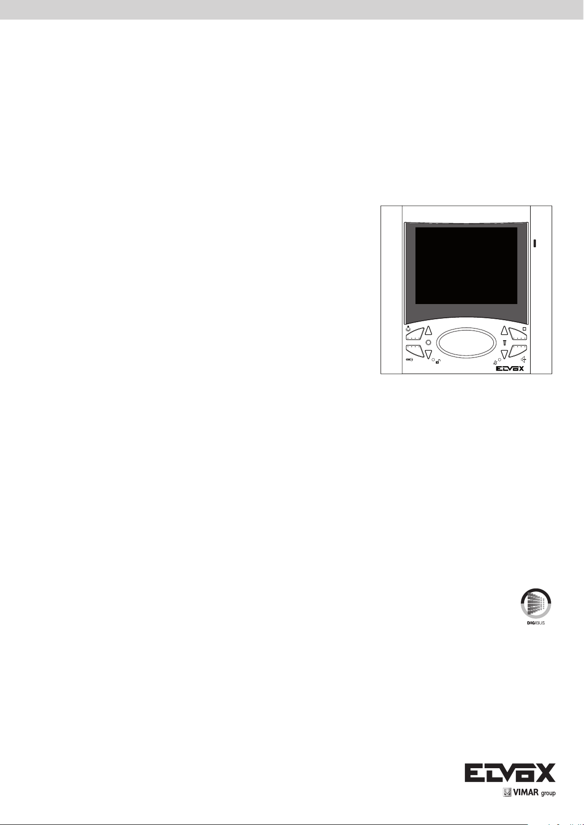
Videocitofono incasso Digibus / Videocitofono tavolo Digibus / Videocitofono parete Digibus
Digibus flush-mount monitor / Digibus desktop monitor / Wall monitor Digibus
Portier-v encastr. Digibus / Portier-v de table Digibus / Portier-v saillie Digibus
UP-Videohaustelefon Digibus / Videohaustelefon Tischgerät Digibus / AP-Monitor Digibus
Videoportero de empotrar Digibus / Videoportero sobremesa Digibus / Videoportero sup. Digibus
Video porteiro de embeber Digibus / Video porteiro montagem saliente Digibus / Video porteiro de mesa Digibus
Page 2
6600
A
C
B
D1
D2
E1
F
G
L M
141 mm
H
I
E2
139 mm
2
PTESDEFRENIT
Page 3
6600
Regolazioni colore e selezione segnale video su
Colour adjustment and video signal selection on
Réglage couleur et sélection signal vidéo sur boucle
Farbeinstellung oder Wahl des Videosignals bei
Regulación color y selección señal vídeo sobre
Regulação da cor e seleção do sinal vídeo sobre
Regolazione colore
Colour adjustment
Réglage couleur
Farbeinstellung
Regulación color
Regulação da cor
doppino o coassiale per 6724
double cable or coaxial for type 6724
ou coaxial pour Art. 6724.
Schleife oder Koaxial für Art. 6724.
cable trenzado o coaxial para Art. 6724.
cabo trançado ou coaxial para Art. 6724
1
Regolazioni colore e selezione segnale video su
doppino o coassiale per 6624
Colour adjustment and video signal selection on
double cable or coaxial for type 6624
Réglage couleur et sélection signal vidéo sur
boucle ou coaxial pour Art. 6624.
Farbeinstellung oder Wahl des Videosignals bei
Schleife oder Koaxial für Art. 6624.
Regulación color y selección señal vídeo sobre
cable trenzado o coaxial para Art. 6624
Regulação da cor e seleção do sinal vídeo sobre
cabo trançado ou coaxial para Art. 6624.
Regolazione colore
Colour adjustment
Réglage couleur
Farbeinstellung
Regulación color
Regulação da cor
Fig. 1
Fig. 2
Commutatore - Switching module
Commutateur - Umschaltrelais
Conmutador - Comutador
D= Doppino, Double cable, Boucle, Schleife
Cable trenzado, Fio trançado
C= Coassiale,Coaxial, Coaxial, Koaxial
Coaxial, Coaxial
Commutatore - Switching module
Commutateur - Umschaltrelais
Conmutador - Comutador
D= Doppino, Double cable, Boucle, Schleife
Cable trenzado, Fio trançado
C= Coassiale,Coaxial, Coaxial, Koaxial
Coaxial, Coaxial
No coax Coax
Commutatore - Switching module
Commutateur - Umschaltrelais
Conmutador - Comutador
Regolazione colore
Colour adjustment
Réglage couleur
Farbeinstellung
Regulación color
Regulação da cor
VIMAR group
Regolazioni colore e selezione segnale video su
doppino o coassiale per 662D
Colour adjustment and video signal selection on
double cable or coaxial for type 662D
Réglage couleur et sélection signal vidéo sur
boucle ou coaxial pour Art. 662D
Farbeinstellung oder Wahl des Videosignals bei
Schleife oder Koaxial für Art. 662D
Regulación color y selección señal vídeo sobre
cable trenzado o coaxial para Art. 662D
Regulação da cor e seleção do sinal vídeo sobre
cabo trançado ou coaxial para Art. 662D
PTESDEFRENIT
3
Page 4
6600
Il manuale istruzioni è scaricabile dal sito
www.vimar.com
REGOLE DI INSTALLAZIONE.
L’installazione deve essere effettuata con l’osservanza delle disposizioni regolanti l’installazione del
materiale elettrico in vigore nel Paese dove i prodotti
sono installati.
CONFORMITÀ NORMATIVA.
Direttiva EMC
Norme EN 61000-6-1, EN 61000-6-3.
INFORMAZIONE AGLI UTENTI AI SENSI
DELLA DIRETTIVA 2012/19/UE (RAEE)
Al fine di evitare danni all’ambiente e alla
salute umana oltre che di incorrere in san-
zioni amministrative, l’apparecchiatura che
riporta questo simbolo dovrà essere smaltita separatamente dai rifiuti urbani ovvero riconsegnata
al distributore all’atto dell’acquisto di una nuova.
La raccolta dell’apparecchiatura contrassegnata
con il simbolo del bidone barrato dovrà avvenire in
conformità alle istruzioni emanate dagli enti territorialmente preposti allo smaltimento dei rifiuti. Per
maggiori informazioni contattare il numero verde
800-862307.
DESCRIZIONE:
Videocitofono viva voce bicanale con monitor LCD
a colori 3,5”. Lo schermo del monitor è inclinabile
verticalmente.
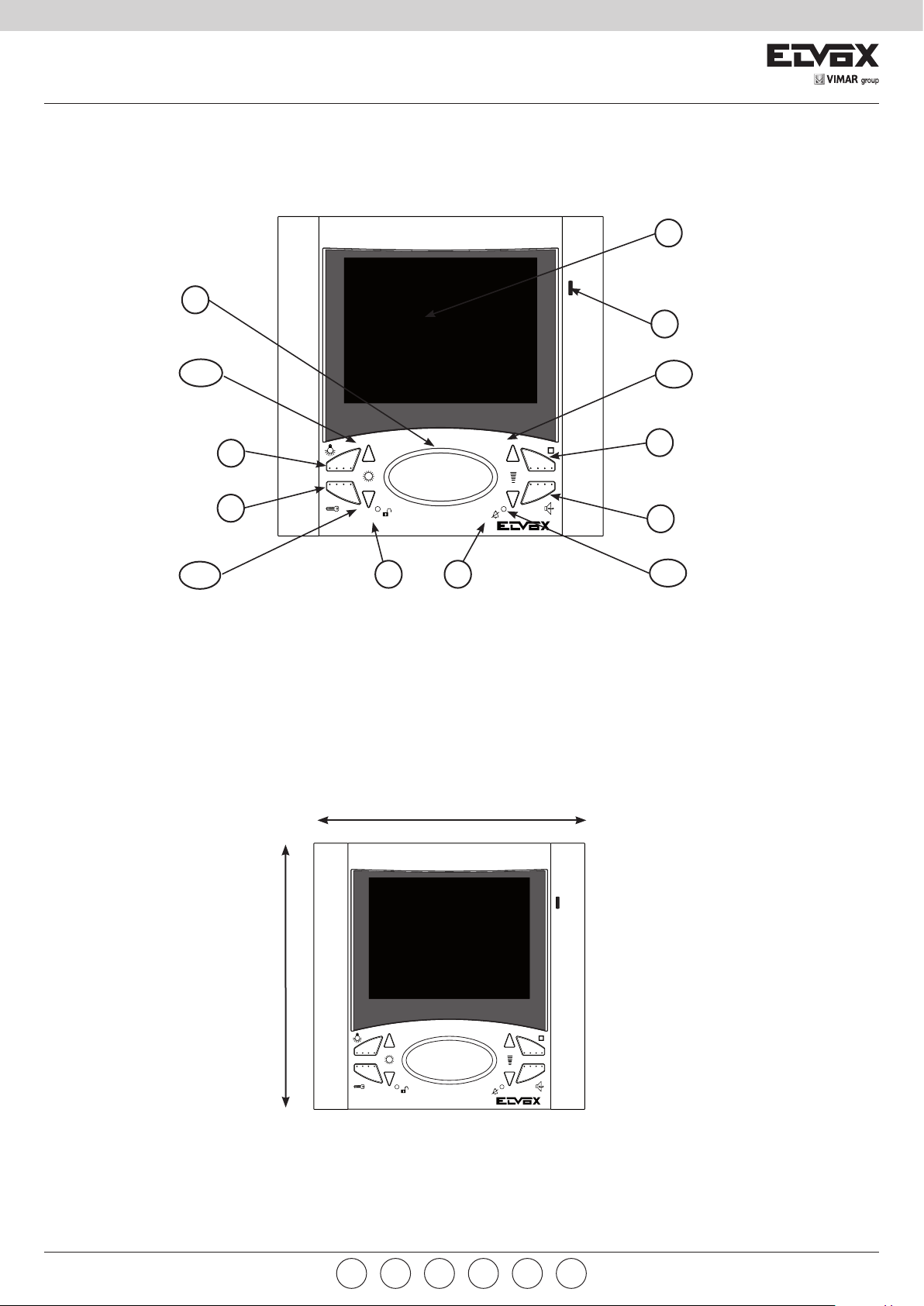
PULSANTI E REGOLAZIONI
A) Monitor LCD 3,5” a schermo piatto.
B) Microfono
C) Altoparlante
D1-D2)
E1-E2)
F)
G)
H) Comando funzione F2. In alternativa è possibi-
I)
L)
M)
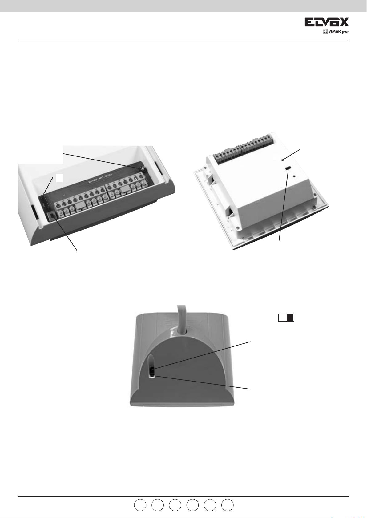
MORSETTIERA DI COLLEGAMENTO
1) Linea di chiamata digitale
2) Linea fonica secondaria
3) Linea di fonica
4) Linea negativo
5) Linea +13.5 Vcc
6) Segnalazione monitor inserito (per suonerie
7) Linea negativo monitor
8) Linea positivo monitor
Coppia pulsanti: scelta suonerie /
regolazione luminosità
Coppia pulsanti: volume suonerie /
regolazione contrasto / regolazione volume
fonica
Comando funzione F1
Comando chiamata verso centralino o
serratura (a monitor chiamato)
le programmare il tasto come funzione F3 o F4
o F5. Il pulsante
F4 o F5 funziona in modo ciclico, ad ogni pressione del tasto cioè cambia funzione.
Pulsante parla/ascolta per abilitazione
conversazione: dopo la chiamata e/o l’accensione del monitor mantenere premuto il pulsante per la conversazione con il posto esterno.
Segnalazione LED attivazione serratura
esterna. La segnalazione è opzionale in relazione al tipo di installazione.
Segnalazione LED per esclusione suoneria / programmazioni varie
supplementari o altri servizi)
programmato come F3 o
9) Linea per chiamata fuoriporta
10) Alimentazione distributore video al piano
11) F1 - collegamento per funzioni ausiliarie da
collegare se indicato nello schema
12) F2 - collegamento per funzioni ausiliarie da
collegare se indicato nello schema
13) Alimentazione segnalatore LED verde
V1) Ingresso segnale video
M) Massa video
V3) ingresso segnale video non coassiale
PROGRAMMAZIONE NUMERO/CODICE DI
CHIAMATA
A monitor spento:
Tenere premuti contemporaneamente i tasti I e H.
Attendere 3 secondi finchè il led rosso M non inizia
a lampeggiare.
A questo punto rilasciare i due tasti I e H e premere
il tasto G entro 5 secondi circa per almeno 3 secondi fino all’accensione fissa del led rosso M. Ora il
dispositivo si trova nello stato programmazione e
può ricevere da una targa o dal programmatore
Art. 950B il numero da codificare. Alla ricezione del
codice e dopo una corretta programmazione, il led
rosso M si spegnerà ed il dispositivo ritornerà allo
stato base.
CHIAMATA FUORIPORTA
Attraverso il cablaggio del morsetto dedicato è possibile differenziare il suono di una chiamata proveniente dal pulsante fuoriporta (ad esempio pianerottolo, entrata secondaria, ecc.) per distinguerla da
quella proveniente da un posto esterno.
Il morsetto 9 prevede l’ingresso per il filo di chiamata
per una targa fuoriporta (il posto esterno 930D) o
per un semplice pulsante N.A. (collegato tra il 9
ed il 5) che fa suonare il videocitofono con la suoneria programmata. È possibile, in seguito ad una
chiamata fuoriporta, fare in modo di accendere il
monitor ed inviare un comando digitale per poter
commutare il segnale video in ingresso con quello
di un’eventuale telecamera sul fuoriporta. Per fare
questo bisogna:
1° abilitare l’accensione del monitor dalla chiamata
fuoriporta, premere a monitor spento D1 e E1 fino al
lampeggio del led rosso M e poi premere H, 2° scegliere quale comando inviare nel bus digitale, premere a monitor spento E1 e E2 fino al lampeggio del
led rosso M e poi premere il tasto corrispondente
alla funzione
FUNZIONE UTENTE-ASSENTE
Questo tipo di funzione consente all’utente, tramite
la targa esterna, di segnalare la propria assenza a
coloro che effettuano la chiamata; può inoltre essere
utilizzata anche nel caso in cui l’utente sia in casa
ma non voglia essere disturbato. Quando la funzione è abilitata il videocitofono che riceve la chiamata
non si accende e non emette nessuna segnalazione acustica ma invia il comando di “UTENTE
ASSENTE” verso un eventuale centralino e fa lampeggiare il LED rosso M, tante volte quante sono le
chiamate non risposte (max 4). Per abilitare questa
funzione, tenere premuti a monitor spento i tasti D1
e E1 fino al lampeggio del led rosso e poi premere I;
il led M si accenderà e resterà acceso per indicare
che la funzione è attiva. Per disabilitare questa
funzione, tenere premuti a monitor spento i tasti D2
e E2 fino al lampeggio del led M e poi premere I; il
led si spegnerà.
SCELTA SUONERIE
È possibile scegliere la suoneria da abbinare alla
chiamata da targa e quella da abbinare alla chiamata fuoriporta. Per scegliere la suoneria per la
chiamata da targa, a monitor spento, premere per
almeno 5 secondi circa D1 o D2, da quando parte
la prima suoneria si possono scorrere tutte le altre
premendo ripetutamente D1 o D2.
Per scegliere la suoneria per la chiamata da fuo-
, .
riporta, a monitor spento, premere per almeno 5
secondi circa i tasti D1 e D2 contemporaneamente
fino all’accensione intermittente del led rosso M,
a questo punto premere D1 o D2 per scegliere la
suoneria.
ESCLUSIONE SUONERIA
Per regolare il volume delle suonerie, a monitor
spento premere E1 o E2 per almeno 5 secondi finchè non parte la suoneria abbinata alla chiamata da
targa. A questo punto aumentare o diminuire il volume premendo rispettivamente E1 o E2. L’esclusione
della suoneria si ha premendo continuamente il
tasto E2 fino all’accensione del led rosso M.
SELEZIONE INGRESSO VIDEO
Il doppio deviatore posto nel retro del monitor, (fig.
1 per 6624 e fig. 2 per 6724) seleziona se il segnale
video di ingresso è di tipo coassiale oppure tramite
doppino.
REGOLAZIONI VIDEO
La regolazione del colore viene fatta tramite un trimmer presente nel retro del monitor (figura 1 per 6624
e figura 2 per 6724). La regolazione della luminosità
e del contrasto vengono fatte a monitor acceso tramite due trimmer digitali premendo rispettivamente i
tasti D1,D2 e E1,E2.
REGOLAZIONI AUDIO/FONICA
Per regolare il volume della fonica bisogna, durante
una conversazione, premere E1 oppure E2 assieme
al tasto I.
SCELTA FUNZIONAMENTO TASTO H (
Di default la pressione del tasto H corrisponde ad
inviare nel bus digitale il comando F2. Con la procedura seguente si può cambiare funzionamento
facendo perdere al tasto la corrispondenza con F2
ed acquisendo la funzionalità F3, F4, F5 in modo
ciclico. Per abilitare la funzione F3, F4, F5 si devono
tenere premuti contemporaneamente a monitor
spento i tasti D1 ed E1 fino al lampeggio del LED
rosso M, dopodichè premere il tasto F (
rosso M si spegnerà. Per disabilitare la funzione F3,
F4, F5 (e ritornare a quella impostata di default): si
devono tenere premuti contemporaneamente i tasti
D2 ed E2 fino al lampeggio del LED rosso M, dopo-
dichè premere il tasto F (
spegnerà .
FUNZIONAMENTO
I videocitofoni 6624, 662D, 6724 possono essere
utilizzati esclusivamente su impianti videocitofonici
ELVOX di tipo digitale DigiBus; per l’alimentazione
si devono utilizzare esclusivamente alimentatori
appartenenti alla gamma DigiBus (es. Art. 6948).
Il sistema DigiBus consente di realizzare tipologie di
impianti nei quali l’identificazione dei dispositivi e dei
comandi è di tipo digitale. A seconda della configurazione dell’impianto, ognuno dei dispositivi collegati
è caratterizzato da un codice numerico a 4 oppure
8 cifre (che deve essere univoco) ed è in grado di
ricevere e spedire dei pacchetti dati all’interno dei
quali sono contenute tutte le informazioni relative
alla gestione della comunicazione; ogni pacchetto
dati è infatti costituito dall’indentificativo del dispositivo di destinazione e dal comando che quest’ultimo
deve effettuare. Tutte le operazioni di comando
tipiche di un sistema videocitofonico quali, ad esempio, chiamata, apertura elettroserratura, accensione
luci scale, ecc., sono quindi codificate. La fonica
per la comunicazione vocale e il segnale video per
la visualizzazione delle immagini sono invece dei
segnali che rimangono di tipo analogico.
); il LED rosso M si
)
); il LED
4
IT
Page 5
6600
The instruction manual is downloadable from
the site www.vimar.com
INSTALLATION RULES.
Installation should be carried out observing current
installation regulations for electrical systems in the
Country where the products are installed.
CONFORMITY.
EMC directive
Standards EN 61000-6-1, EN 61000-6-3.
INFORMATION FOR USERS UNDER DIRECTIVE 2012/19/UE (WEEE)
In order to avoid damage to the environ-
ment and human health as well as any administrative sanctions, any appliance marked with
this symbol must be disposed of separately from
municipal waste, that is it must be reconsigned to
the dealer upon purchase of a new one. Appliances
marked with the crossed out wheelie bin symbol
must be collected in accordance with the instructions issued by the local authorities responsible for
waste disposal.
DESCRIPTION:
Monitor with “open voice” twin channel and 3,5’’
colour LCD screen. The monitor screen may be
vertically sloped.
PUSH-BUTTONS AND ADJUSTMENTS
A) Flat 3,5” LCD screen.
B) Microphone
C) Loudspeaker
D1-D2)
E1-E2)
F)
G)
H) Command function F2. In alternative it is possi-
I)
L) LED Sign for external activation
M)
TERMINAL BLOCK
1) Digital call line
2) Secondary entrance panel audio line
3) Audio line
4) Negative line
5) + 13,5V DC line
6) Inserted monitor signalling (for additional
7) Monitor negative line
8) Monitor positive line
9) Line for outside door call.
Pair of push-buttons:chime choice /
lighting adjustment
Pair of push-buttons: chime volume /
contrast adjustment / volume adjustment
audio line
Command function F1
Command call to the switchoboard or
door lock (when monitor is called)
ble to program the push-button as function F3
or F4 or F5. The push-button
as F3 or F4 or F5 operates in cyclical way, i.e.
each pressure of push-button changes function.
Push-button talk / listen, for conversation
enabling. After the call and/or switch-on of the
monitor, hold the push-button down for conversation with the speech unit.
Led indicator for chime exclusion / vari-
ous programmings
chimes or other services)
programmed
10) Supply voltage for video floor distributor
11) F1 - connection for auxiliary functions, to
be connected if indicated on the diagram.
12) F2 - connection for auxiliary functions, to
be connected if indicated on the diagram.
13) Supply voltage for green LED indicator
V1) Input for the video signal
M) Video earth
V3) Video signal input for cable other than coaxial
PROGRAMMING THE NUMBER/CALL CODE
With monitor switched off, operate as it follows:
Press simultaneously and hold the “I” and “H”
push-buttons.
Wait for 3 seconds until the red led “M” starts flashing.
Release both push-buttons “I” and “H” and press
the “G” push-button within 5 seconds for at least 3
seconds until the red LED “M” is steadily lit. Now the
device is on programming mode and can receive the
number to code from an entrance panel or from the
programmer Art. 950B. At the code reception and
after a correct programming, the red led M switches
off and the device returns to the basic mode.
OUTDOOR CALL
Through a dedicated terminal cabling it is possible
to discriminate the call tone coming from an outdoor
push-button (for example passage, secondary entry
etc.) from that coming from an outdoor station.
Terminal 9 is preset for the input of the call wire for
an apartment entrance panel (the speech unit Art.
930D) or for a simple push-button N.A. (connected
between 9 and 5) which make the monitor ring
through a programmed chime. On receiving an
apartment outdoor call it is possible to turn the monitor on and send a digital command able to switch
the video signal in the entrance with that of a possible camera on the apartment door. To do so you
must enable the monitor switching on (from outdoor
call unit by pressing the “D1” and “E1” push-buttons,
being the monitor switched off, until the red led “M”
flashes and then pressing the “H” push-button) and
choose the command to route (by pressing the “E1”
and “E2” push-buttons (with monitor off) until the led
M flashes and press then the push-button corre-
sponding to the function,
“UNANSWERED CALL” FUNCTION
By means of an external entrance panel this type
of function allows the user to signal his absence to
the calling visitor; it may also be used when the user
is at home, but does not want to answer. When the
function is enabled the video-interphone receiving
the call does not emit an acoustic signal, but sends
a “USER ABSENT” command to a possible switchboard and, in addition, makes the “M” red LED flash
as many times as the ananswered calls (max 4). To
enable this function, it is enough to press and hold
the “D1” and “E1” push-buttons (with monitor off)
until the led M lights up, then press the “I” push-button; the Led “M” will light up and remain ON to show
the function is active.
To disable this function, with monitor off, press and
hold the “D2” and “E2” push-buttons until the led M
lights up and then press the “I” push-button; the led
switches off.
CHOOSING THE RING TONE
With monitor off, press push-button “D1” or “D2”
for nearly 5 seconds to choose the ring tone for the
entrance panel call; when the first ring tone sounds
you can scroll all the ring tones by pressing several
times “D1” or “D2”.
To choose the outdoor call ring tone, (always with
monitor off) press “D1” and “D2” simultaneously
for nearly 5 seconds until the red led “M” flashes
intermittently; now press “D1” or “D2” to choose the
ring tone.
, .
CHIME EXCLUSION
To adjust the chime volume, with monitor off press
“E1” or “E2” for at least 5 seconds until the chime
associated with the entrance panel starts ringing.
Now increase or decrease the volume by pressing
the “E1” or “E2” push-button respectively. You can
get the chime exclusion by pressing continuously
the “E2” push-button until the red led “M” switches
on.
SELECTING THE VIDEO INPUT
The double switch on the rear of monitor (fig. 1 for
6624 und fig. 2 for 6724) selects the input video
signal: for the coaxial type cable or for the double
cable.
VIDEO ADJUSTMENT
The colour adjustment is carried out by a trimmer
on the rear of monitor (fig. 1 for 6624 und fig. 2 for
6724). The brightness and contrast adjustment is
made with monitor on and by two digital trimmers
pressing the “D1”, “D2” and “E1”, “E2” push-buttons
respectively.
AUDIO ADJUSTMENT
To adjust the audio volume, (during a conversation)
press the “E1” or “E2” push-button together with the
“I” push-button.
CHOOSING THE “H” PUSH-BUTTON
OPERATION (
As default the pressure of push-button H routes the
F command to the digital BUS.
With the following procedure it is possible to change
the operation making the push-button lose its correspondence to “F2” and adquiring the F3, F4, F5
functions in a cyclical way. To enable the F3, F4
and F5 functions press and hold down (with monitor
off) the D1 and E1 push-buttons at the same time
until the red led M flashes, press then the F
push-button (
ble the F3, F4, F5 function (the one set as default)
press the D2 and E2 push-buttons at the same time
until the red LED M flashes, now press the F
push-button (
OPERATION
Monitors type 6624, 662D, 6724 must be used only
on digital Digibus type ELVOX video-interphone
installations; for the supply voltage use only the digibus range power supplies (for example type 6948).
The digibus system allows you to carry out installations with digital type device and command identification. According to the installations configuration,
each device connected is identified by a 4 or 8
univocal numerical code and it is able to receive and
send a data packet containing all the information
related to the communication management; in fact
each data packet includes the identification of the
destination device and the command to be carried
out. All typical command operations of a video-interphone system, such as call, electrical lock release,
stair-light switching on etc., are then codified.The
audio and video signals are, on the contrary, analogical type signals.
)
); the red LED M turns off. To disa-
) ; the red LED M turns off .
VIMAR group
EN
5
Page 6
6600
Télécharger le manuel d’instructions sur le
site www.vimar.com
RÈGLES D’INSTALLATION.
L’installation doit être effectuée dans le respect
des dispositions régulant l’installation du matériel
électrique en vigueur dans le Pays d’installation
des produits.
CONFORMITÉ AUX NORMES.
Directive EMC
Normes EN 61000-6-1, EN 61000-6-3.
COMMUNICATION AUX UTILISATEURS
CONFORMÉMENT À LA DIRECTIVE
2012/19/UE (DEEE)
Pour protéger l’environnement et la santé
des personnes et éviter toute sanction administrative, l’appareil portant ce symbole ne devra pas être
éliminé avec les ordures ménagères mais devra être
confié au distributeur lors de l’achat d’un nouveau
modèle. La récolte de l’appareil portant le symbole
de la poubelle barrée devra avoir lieu conformément
aux instructions divulguées par les organisms régionaux préposés à l’élimination des déchets.
DESCRIPTION :
Monitor à deux canaux à vive voix et écran de 3,5’’
en couleurs. L’écran du moniteur peut être incliné
verticalement.
BOUTONS-POSSOIRS ET RÉGLAGES
A) Moniteur 3,5” à écran plat.
B) Microphone
C) Haut-parleur
D1-D2)
E1-E2)
F)
G)
H) Commande fonction F2. En alternative il est
I)
L)
M)
BORNIER DE RACCORDEMENT
1) Ligne d’appel digital
2) Ligne de phonique sécondaire
3) Ligne de phonique
4) Ligne negatif
5) Ligne +13,5 V c.c.
6) Signalisation moniteur enclenché (pour sonne-
7) Ligne negatif moniteur
Paire boutons-poussoirs: choix sonne-
rie / réglage luminosité
Paire boutons-poussoirs: volume sonnerie / réglage contraste / réglage volume
phonique
Commande fonction F1
Commande appel vers le standard ou
gâche (avec moniteur appelé)
possible de programmer le bouton-poussoir
comme fonction F3 ou F4 ou F5. Le bou-
ton-poussoir
ou F5 fonctionne de façon cyclique, c’est-àdire chaque pression du bouton-poussoir
change fonction.
Bouton-poussoir parle-écoute, pour validation conversation. Après l’appel et/ou l’allumage du monteur, appuyer continuellement
sur le bouton-poussoir pour la conversation
avec le poste extérieur.
Signalisation LED activation externe
Signalisation LED para exclusion sonne-
rie / diverses programmations.
rie supplémentaire et d’autres services)
programmé comme F3 ou F4
8) Ligne positif moniteur
9) Ligne pour appels porte palière
10) Alimentatin distributeur vidéo à l’étage
11) F1 - raccordement pour fonctions auxiliaires, à
connecter si indiqué dans le schéma
12) F2 - raccordement pour fonctions auxiliaires, à
connecter si indiqué dans le schéma
13) Alimentation signalisateur LED verte.
V1 Entrée signal vidéo
M) Masse vidéo
V3) Entrée signal vidéo non coaxial
PROGRAMMATION NUMÉRO/ CODE D’APPEL
Avec moniteur éteint :
Appuyer simultanément et maintenir enfoncés
les boutons-poussoirs « I » et « H ». Attendre 3
secondes jusqu’à la led rouge « M » commence
à clignoter.À ce point relâcher les deux poussoirs
« I » et « H »; appuyer sur le poussoir « G » d’ici
5 secondes pour au moins 3 secondes jusqu’à
l’allumage fixe de la led rouge « M ». Maintenant
le dispositif se trouve dans le mode de programmation et peut recevoir le numéro à coder depuis
une plaque de rue ou depuis le programmateur Art.
950B. À la réception du code et après une correcte
programmation, la led rouge M s’éteint et le dispositif retourne au mode base.
APPEL PORTE PALIÈRE
La borne 9 est pour l’entrée du fil d’appel pour une
plaque porte palière (le poxte externe l’Art. 930D) ou
pour un simple poussoir N.A. (raccordé entre le 9 et
le 5) qui fait sonner le moniteur au moyen d’une
sonnerie programmée. Suite à un appel de la porte
palière il est possible d’allumer le moniteur et d’envoyer une commande digitale pour pouvoir commuter le signal vidéo en entrée avec celui d’une caméra eventuelle à la porte palière. Pour faire cela il faut
valider l’allumage du moniteur (en appuyant appel
porte palière, avec moniteur déclenché, sur “D1” et
“E1” jusqu’à ce que la led rouge « M » clignote et
ensuite en appuyant sur la touche « H ») et choisir
la commande qu’on veut envoyer (en appuyant,
avec moniteur déclenché, sur « E1 » et « E2 »
jusqu’à la led M clignote et ensuite appuyer sur la
touche correspondant à la fonction
FONCTION « APPEL SANS RÉPONSE »
Ce type de fonction permet à l’usager, au moyen
d’une plaque de rue, de signaliser la propre absence
à celui qui appelle ; de plus, elle peut être utilisée
aussi lorsque l’usager est dans la maison, mais il
ne veut pas répondre. Quand la fonction est validée
le vidéo-interphone qui reçoit l’appel n’émet aucune
signalisation acoustique, mais il envoi la commande
« USAGER ABSENT » vers un standard éventuel
et, en plus, il fait clignoter la LED rouge « M » autant
de fois combien les appels sans réponse (max. 4).
Pour valider cette fonction, avec moniteur éteint,
maintenir enfoncés les boutons « D1 » et « E1 »
jusqu’à la led clignote “M” et ensuite appuyer sur «
I »; la Led s’allumera et restera allumée pour indiquer que la fonction est active.. Pour invalider cette
fonction, il suffit de maintenir enfoncé les poussoirs
« D2 » et « E2 » avec moniteur éteint jusqu’à la led
clignote et ensuite appuyer sur «I » ; la led s’éteint.
CHOIX DES SONNERIES
Il est possible de choisir la sonnerie à associer à
l’appel depuis la plaque de rue et celle à associer
à l’appel depuis la porte palière. Avec moniteur
éteint appuyer sur « D1 » ou « D2 » pour au moins
5 secondes pour choisir la sonnerie pour les appels
depuis la plaque de rue, dès que la première sonnerie sonne on peut faire défiler toutes les sonneries
en appuyant plusieurs fois sur les touches “D1”
et “D2”. Toujours avec moniteur éteint, on peut
choisir la sonnerie pour les appels porte palière en
appuyant sur les touches “ D1“ et “D2” simultanément pour environ 5 secondes jusqu’à la led rouge
, .
«M» s’allume avec lumière intermittente; maintenant
appuyer sur “D1” ou “D2” pour choisir la sonnerie.
EXCLUSION DE LA SONNERIE
Pour régler le volume des sonneries, avec moniteur
éteint appuyer sur « E1 » ou « E2 » pour au moins
5 secondes jusqu’à ce que la sonnerie associée à
l’appel depuis la plaque de rue ne sonne. A ce point
augmenter ou diminuer le volume en appuyant sur
« E1 » ou «E2 » respectivement. On obtient l’exclusion de la sonnerie en appuyant continuellement sur
la touche « E2 » jusqu’à la led rouge « M » s’allume.
SÉLECTION ENTRÉE VIDÉO
Le double commutateur placé à l’arrière du moniteur
(fig. 1 pour 6624 et fig. 2 pour 6724) sélectionne
l’entrée vidéo: type pour câble coaxial ou du type
pour «boucle».
RÉGLAGE VIDÉO
Le réglage de la couleur est fait au moyen du trimmer présent à l’arrière du moniteur (fig. 1 pour 6624
et fig. 2 pour 6724). Le réglage de la luminosité et
du contraste est fait avec moniteur allumé au moyen
de deux trimmers digitaux en appuyant sur les deux
touches D1, D2 et E1, E2 respectivement.
RÉGLAGE DE L’AUDIO
Pour régler le volume de l’audio il faut appuyer (pendant une conversation) sur le bouton-poussoir «E1 »
ou « E2 » simultanément avec le poussoir «I».
CHOIX DU FONCTIONNEMENT DU BOUTON-
POUSSOIR “H” (
Par défaut (default) la pression du bouton-poussoir
H envoie la commande F2 au digital BUS. Avec la
procédure suivante on peut changer le fonctionnement en faisant perdre la correspondance avec F2
au bouton-poussoir et en acquérant la fonction F3,
F4, F5 de façon cyclique. Pour valider les fonctions
F3, F4, F5 ont doit maintenir enfoncé simultanément
(avec moniteur éteint) les boutons D1 et E1 jusqu’à
ce que la LED rouge M clignote, depuis appuyer sur
le bouton F (
invalider la fonction F3, F4, F5 (celle programmée
par défaut): appuyer et maintenir le doigt sur le boutons D2 et E2 jusqu’à ce que la LED rouge M cli-
gnote, ensuite appuyer sur le bouton F (
LED rouge M s’éteint .
FONCTIONNEMENT
Le vidéo-interphones 6624, 662D, 6724 peut être
utilisé exclusivement dans les installations de portier-vidéo ELVOX type digital DigiBus; pour l’alimentation on doit utiliser seulement alimentations de la
série DigiBus (par exemple Art. 6948). Le système
DigiBus permet de réaliser types d’installations dans
lesquels l’identification des dispositifs et des commandes est de type digital. Selon l’identification de
la configuration de l’installation, chaque dispositif
raccordé est caractérisé par un code numérique univoque à 4 ou 8 chiffres et peut recevoir et envoyer
des paquets données contenant tous les renseignements relatifs à la gestion de la communication;
chaque paquet données contient l’identification du
dispositif de destination et la commande qu’il doit
effectuer. Toutes les opérations typiques de commande d’un système vidéo-interphonique telles que,
par exemple, appel, ouverture de la gâche électrique, allumage lumière escalier etc., sont donc
identifiées.
La phonique pour la communication vocale et le
signal vidéo pour la visualisation des images sont,
au contraire, des signaux analogiques.
)
) ; la LED rouge M s’éteint. Pour
) ; la
6
FR
Page 7

6600
Die Bedienungsanleitung ist auf der Website
www.vimar.com zum Download verfügbar
INSTALLATIONSVORSCHRIFTEN.
Die Installation hat gemäß den im jeweiligen Verwendungsland der Produkte geltenden Vorschriften zur
Installation elektrischer Ausrüstungen zu erfolgen.
NORMKONFORMITÄT.
EMC-Richtlinie
Normen DIN EN 61000-6-1, EN 61000-6-3.
VERBRAUCHERINFORMATION GEMÄSS RICHTLINIE 2012/19/UE (WEEE)
Zum Schutz von Umwelt und Gesund-
heit, sowie um Bußgelder zu vermeiden,
muss das Gerät mit diesem Symbol getrennt vom
Hausmüll entsorgt oder bei Kauf eines Neugeräts
dem Händler zurückgegeben werden. Die mit dem
Symbol der durchgestrichenen Mülltonne gekennzeichneten Geräte müssen gemäß den Vorschriften
der örtlichen Behörden, die für die Müllentsorgung
zuständig sind, gesammelt warden.
BESCHREIBUNG:
2-Canal “ Frei-Handiger “mit 3,5’’ Farbbildschirm.
Der Bildschirm des Monitors kann senkrecht geneigt
werden.
TASTEN UND EINSTELLUNGEN
A) 3,5” LCD-Flachbildschirm.
B) Mikrofon
C) Lautsprecher
D1-D2)
E1-E2)
Lautstärkeeinstellung Audiolinie
F)
G)
H) Befehl Funktion F2. Als Alternative ist es mög-
I)
L)
M)
ANSCHLUSSKLEMMENLEISTE
1) Digitale Rufleitung
2) Sekundär-Sprechleitung
3) Sprechleitung
4) Minusleitung
5) Leitung +13.5 VDC
6) Eingeschaltete Monitoranzeige (für
7) Monitor-Minusleitung
8) Monitor-Plusleitung
9) Leitung für Etagenruf
Paar Tasten: Wahl der Klingeln /
Helligkeiteinstellung
Paar Tasten: Klingellautstärke /
Kontrasteinstellung /
Befehl Funktion F1
Befehl Ruf zur Zentrale oder Türöffner
(mit angerufenem Monitor)
lich di Taste als Funktion F3 oder F4 oder F5
zu programmieren. Die Taste
miert als F3 oder F4 oder F5 arbeitet in zyklischem Zustand, dass heißt jeder Druck ändert
Funktion.
„Sprechen-Hören“-Taste, für
Gesprächsfreigabe. Für Verbindung mit der
Außenstation nach Ruf und/oder
Monitoreinschaltung (Taste gedrückt halten).
Externaktivierunganzeige LED
Led-Anzeige für die Klingelausschaltung
/ verschiedene Programmierungen
Zuzatsklingel und andere Dienste)
program-
10) Spannungsversorgung für video Stockverteiler
11) F1 - Anschluss für Zusatzfunktionen, insofern
im Schaltplan vorgesehen
12) F2 - Anschluss für Zusatzfunktionen, insofern
im Schaltplan vorgesehen
13) Spannungsversorgung für grüne LED-Anzeige.
V1) Eingang für den Videosignal
M) Video-Erde
V3) Eingang für den Video-Signal ohne Koaxkabel.
PROGRAMMIERUNG DER NUMMER/ RUFCODE
Die Tasten beim ausgeschalteten Monitor wie folgend drücken:
Die Tasten „I“ und „H“ gleichzeitig drücken und
gedrückt halten.
Warten sie auf 3 Sekunden bis die rote Led „M“
blinkt.
Die zwei Tasten „I“ und „H“ loslassen und innerhalb
5 Sekunden die „G“ Taste für zirka 3 Sekunden
drücken bis die rote Led „M“ sich beleuchtet mit
Festlicht. Jetzt befindet sich die Vorrichtung auf
Programmierungszustand und kann von einem
Klingeltableau oder dem Programmiergerät Art.
950B die kodifizierende Nummer erhalten. Nach
Empfang des Codes und nach einer vollkommenen
Programmierung, erlischt die rote Led M und geht
die Vorrichtung auf die Grundzustand zurück.
WOHNTÜRRUF
Die Klemme 9 ist vorbereitet für den Rufdraht für ein
Wohntür-Klingeltableau (außenstelle Art. 930D) oder
für eine einfache Taste (zwischen 9 und 5 angeschlossen), die einen Ton beim Monitor durch eine
programmierte Klingel erzeugt. Nach einem Ruf von
der Wohntür ist es möglich den Monitor einzuschalten und einen digitalen Befehl übertragen um das
Videosignal beim Eingang mit dem einer eventuellen
Kamera an der Wohntür umschalten zu können. Um
diese Funktion zu ermöglichen ist der
Monitoreinschaltung freizugeben (durch Drücken mit
ausgeschaltetem Monitor) der „D1“ und „E1“ Tasten
bis die rote Led M blinkt und dann die „H“ Taste drücken und wählen Sie den Befehl zu übertragen (bei
Drücken mit ausgeschaltetem Monitor) die „E1“ und
„E2“ Tasten bis die rote Led blinkt und dann die auf
der zuübertragenden Funktion entsprechende Taste
, .
„UNANTWORTETER RUF“- FUNKTION
Durch ein Externklingeltableau erlaubt diese
Funktion dem Benutzer ihre Abwesenheit am
Rufenden anzuzeigen; dieselbe Funktion kann auch
benutzt werden als der Benutzer zu Haus ist, aber
antworten will er nicht, Soll diese Funktion freigegeben wird, so überträgt das Video-Haustelefon (das
den Ruf empfängt) keine akustische Anzeige, aber
nur einen „BENUZTER ABWESEND“-Befehl zu
einer eventuellen Zentrale, und makt die rote LED
„M“ blinken wie viele Male wie die unantworteten
Rufe (max. 49). Um diese Funktion freizugeben ist
es genug (mit ausgeschaltetem Monitor) die Tasten
„E1“ und „E2“ zu drücken und gedrückt zu halten
bis die Led blinkt und dann die „I“ Taste drücken;
die Led “M” wird sich beleuchten und beleuchtet
bleiben um zu zeigen dass die Funktion aktiv ist. Um
die Funktion auszuschalten, mit ausgeschaltetem
Monitor, die „D2“ und „E2“ Tasten drücken bis die
M Led blinkt und dann die „I“ Taste drücken; die Led
erlischt.
AUSWAHL DES RUFTONS
Man kann wählen den Rufton, der am
Klingeltableauruf und jener, der am Wohntüruf
zugewiesen werden kann. Um den Rufton für den
Klingeltableauruf (mit ausgeschaltetem Monitor)
auszuwählen die „D1“ oder „D2“ Taste für zirka
5 Sekunden drücken; nachdem der erste Rufton
ertönt hat, kann man durch mehrmals Drücken der
„D1“ oder „D2“ Taste alle Klingeln blättern. Um den
Rufton für den Wohntürruf auszuwählen, immer mit
ausgeschaltetem Monitor, die „D1“ und „D2“ Tasten
gleichzeitig drücken für zirka 5 Sekunden bis die
rote Led M sich intermittierend leuchtet; um die
Klingel zu wählen die Taste „D1“ oder „D2“ drücken.
AUSSCHALTUNG DER KLINGEL
Um die Lautstärke einzustellen, mit eingeschaltem Monitor (Abb. 1 für 6624 und Abb. 2 für 6724)
die „E1“ oder „E2“ Taste für 5 Sekunden drücken
bis die mit dem Klingeltableau zugewiese Klingel
ertönt. Die Lautstärke mittels der entsprechenden
Taste „E1“ oder „E2“ erhöhen oder vermindern. Die
Klingelausschaltung erfolgt durch ständiges Drücken
der „E2“ Taste bis die rote Led M sich beleuchtet.
AUSWAHL DES VIDEO-EINGANGS
Der Doppelumschalter, der sich hinter dem Monitor
(Abb. 1 für 6624 und Abb. 2 für 6724) befindet,
wählt den Koax-Eingangsignal oder den SchleifeEingangssignal.
EINSTELLUNG DER VIDEO
Die Farbeinstellung wird mittels eines an der
Rückseite des Monitors Trimmers durchgeführt.
Die Helligkeit- und der Kontrasteinstellung wird mit
eingeschaltetem Monitor und durch zwei digitalen
Trimmer bei Drücken der entsprechenden Tasten
„D1“, „D2“ und „E1“, „E2“ durchgeführt.
EINSTELLUNG DER AUDIO-LINIE
Um die „Audio“-Lautstärke einzustellen, während
eines Gesprächs die „E1“ oder „E2“. Taste gleichzeitig mit der „I“ Taste drücken.
WAHL DES TASTEBETRIEBS « H » (
Als Default der Druck der Taste H überträgt den
Befehl F2 zum digitalen BUS. Mit folgender
Prozedur kann der Betrieb verändert werden und die
Übereinstimmung der Taste mit F2 abkommen lassen und durch die Funktionen F3, F4, F5 in zyklischer Weise annehmen. Um die Funktion F3, F4, F5
freizugeben die Tasten D1 und E1 (mit ausgeschaltetem Monitor) gleichzeitig drücken und gedrückt
halten bis die rote LED M blinkt, dann die Taste F
drücken (
F4, F5 Funktion auszuschalten (die als Default programmiert wurde): die D2 und E2 Tasten gleichzeitig
drücken und gedrückt halten bis die rote LED M
blinkt, dann die F Taste drücken (
M erlischt.
BETRIEB
Das Video-Haustelefons Art. 6624, 662D, 6724
muss nur bei Digital-DigiBus ELVOX Anlagen verwendet werden; für die Versorgungsspannung
können nur Netzgeräte Baureihe DigiBus (zB.
Art. 6948) genutzt werden. Das DigiBus-System
ermöglicht Anlagen mit Digitalidentifizierung
der Vorrichtungen und Befehle. Gemäß der
Konfiguration der Anlage, wird jede angeschlossene Vorrichtung mittels eines 4 oder 8 eindeutigen numerischen Codes identifiziert und kann sie
Data-Packets, die alle bezüglichen Informationen
der Steuerungskommunication enthalten, empfangen und übertragen; jedes Data-Packet
umfasst die Identifizierung des Bestimmungsorts
der Vorrichtung und des entsprechenden durchfürenden Befehls. Alle bestimmten Betriebe des
Befehls eines Video-Haustelefonanlage-Systems
wie, zum Beispiel, Ruf, Türöffnung, TreppenlichtBeleuchtung usw., werden kodifiziert. Die Audiound Videosignale sind, dagegen, analogische
Signale.
); die rote LED M erlischt. Um die F3,
)
); die rote LED
VIMAR group
DE
7
Page 8

6600
El manual de instrucciones se puede descargar en la página web www.vimar.com
NORMAS DE INSTALACIÓN.
El aparato se ha de instalar en conformidad con
las disposiciones sobre material eléctrico vigentes
en el País.
CONFORMIDAD NORMATIVA.
Directiva EMC
Normas EN 61000-6-1 y EN 61000-6-3.
INFORMACIÓN A LOS USUARIOS DE
CONFORMIDAD CON LA DIRECTIVA
2012/19/UE (RAEE)
Para evitar perjudicar el medio ambiente y
la salud de las personas, así como posibles sanciones administrativas, el aparato marcado con este
símbolo no deberá eliminarse junto con los residuos
urbanos y podrá entregarse en la tienda al comprar
uno nuevo. La recogida del aparato marcado con el
símbolo del contendedor de basura tachado deberá realizarse de conformidad con las instrucciones
emitidas por las entidades encargadas de la eliminación de los residuos a nivel local.
DESCRIPCIÓN:
Monitor con dos canales a viva voz y pantalla de
3,5’’ en color. La pantalla puede ser inclinada verticalmente.
PULSADORES Y REGULACIONES
A) Pantalla plana de cristal líquido de 3,5”.
B) Micrófono
C) Altavoz
D1-D2)
E1-E2)
F)
G)
H) Mando función F2. En alternativa es posible
I)
L)
M)
REGLETA DE CONEXIONES
1) Línea de llamada digital
2) Línea fónica secundaria
3) Línea de fónica
4) Línea negativo
5) Línea + 13,5V c.c.
6) Señalización monitor insertado (para timbres
7) Línea negativo monitor
8) Línea positivo monitor
Par pulsadores:elección timbres /
regulación luminosidad
Par pulsadores: volumen timbres /
regulación contraste / regulación volumen
fónica
Mando Función F1
Mando llamada hacia la central o cerra-
dura (con monitor llamado)
programar el pulsador como función F3 o F4 o
F5. El pulsador
o F5 funciona de manera cíclica, es decir
cada presión del pulsador cambia función.
Pulsador habla/escucha, para habilitación
conversación. Manter premido o botão para a
conversação com o posto externo. Permite o
autoacendimento do monitor sem ter sido chamado (a função é opcional em relação ao tipo
de instalação).
Señalización activación externa LED
Señalización LED exclusión timbre / pro-
gramaciones varias
suplementarios o otros servicios).
programado como F3 o F4
9) Línea para llamada fuera de la puerta
10) Alimentación distribuidor vídeo a la planta
11) F1 - conexionado para funciones auxiliares;
conectar si indicado en el esquema
12) F2 - conexionado para funciones auxiliares;
conectar si indicado en el esquema
13) Alimentación LED indicador verde
V1) Entrada señal vídeo
M) Tierra vídeo
V3) Entrada señal vídeo para cable no coaxial.
PROGRAMACIÓN NÚMERO/ CÓDIGO DE LLA-
MADA
Con monitor pagado:
Pulsar simultáneamente los pulsadores “I” y “H”
y mantenerlos presionados. Esperar 3 segundos
hasta que el led rojo M comience a parpadear. A
este punto soltar los dos pulsadores “I” y “H”, pulsar
el pulsador “G” dentro de cerca 5 segundos por
almenos 3 segundos hasta que le led rojo “M” se
encienda. Ahora el dispositivo se encuentra en el
estado de programación y puede recibitr el número
para programar desde una placa o desde el programador Art. 950B. A la recepción del código y después de una correcta programación, el led rojo M se
apaga y el dispositivo vuelve al estado base.
LLAMADA PUERTA APARTAMIENTO
El borne “9” está predispuesto para el hilo de llamada para una placa puerta apartamiento (aparato
externo el Art. 930D) o para un simple pulsador N.A.
(conectado entre el 9 y el 5) que hace tocar el monitor con un timbre programado. Tras una llamada
desde la puerta apartamiento es posible encender el
monitor y enviar un mando digital para poder conmutar la señal vídeo en entrada con aquella de una
cámara eventual en la puerta apartamiento. Para
hacer esto hay que habilitar el encendido del monitor (da llamada puerta apartamiento pulsando, con
monitor apagado, el pulsador “D1” y “D2” hasta que
el led rojo “M” parpadee y luego pulsando “H”) y
escoger el mando que hay que enviar (pulsando,
con monitor apagado, “E1” y “E2” hasta que el led M
parpadee y luego pulsar el pulsador correspondien-
te a la función
FUNCIÓN “LLAMADA SIN REPUESTA”
Este tipo di función permite al usuario, por medio
de una placa externa, de señalizar la propia ausensia a quien efectúa una llamada; además puede
ser utilizada también cuando el usuario está en la
vivienda, mas no quiere responder.
Cuando la función está habilitada el videoteléfono
que recibe la llamada no emite alguna señalización acústica, mas envia el mando “USUSARIO
AUSENTE” hacia una eventual central y, además,
hace parpadear el LED rojo “M” tantas veces cuantas son las llamadas sin respuestas (4 max.). Para
habilitar esta función es suficiente, siendo el monitor
apagado, pulsar y mantener presionados los pulsadores “D1” y “E1” hasta que el led parpadee y luego
pulsar “I”; el Led M se enciende e quedrá encendio
para indicar que la función es activa. Para deshabilitar esta función, es suficiente tener presionados,
con monitor apagado, los pulsadores “D2” y “E2”
hasta que el led parpadee y luego pulsar “I”; el el
se apaga.
ELECCIÓN DE LOS TIMBRES
Es posible escoger el timbre que hay que asociar
a la llamada desde la placa y aquello que hay que
asociar a la llamada desde la puerta apartamiento.
Con monitor apagado pulsar por al menos 5 segundos los pulsadores “D1” o “D2” para elegir el timbre
de la llamada desde la placa; cuando el primer
timbre toca se pueden desfilar todos los otros presionando repetidamente “D1” o “D2”.
Simpre con monitor apagado, para elegir el timbre para la llamada puerta apartamiento, pulsar
por al menos 5 segundos los pulsadores “D1” y
, .
“D2” simultáneamente hasta que el led rojo “M” se
encienda con luz intermitente; pulsar ahora “D1” o
“D2” para elegir el timbre.
EXCLUSIÓN TIMBRE
Para regular el volumen de los timbres, con monitor
apgado, pulsar “E1” o “E2” por al menos 5 segundos
hasta que toque el timbre associado a la llamada
desde la placa. Aumentar o disminuir el volumen
pulsando “E1” o “E2” respectivamente. La exclusión
del timbre se obtiene pulsando continuamente el
puslandor “E2” hasta que el led rojo “M” se encienda.
SELECCIÓN ENTRADA VÍDEO
El doble conmutador que se encuentra detrás del
monitor (fig. 1 para 6624 y fig. 2 para 6724), selecciona la señal vídeo para el cable coaxial o para el
cable trenzado.
REGULACIÓN VÍDEO
La regulación del color se hace por medio de un
trimmer que se encuentra detrás del monitor (fig.
1 para 6624 y fig. 2 para 6724). La regulación de
la luminosidad y del contraste se hace con monitor
encendido y por medio de dos trimmers digitales utilizando los pulsadores “D1”, “D2” y “E1”, “E2”.
REGULACIÓN AUDIO
Para regular el volumen del audio, durante una conversación pulsar “E1” o “E2” junto con el pulslador
“I”.
ELECCIÓN DEL FUNCIONAMIENTO DEL
PULSADOR (
Por defecto (default) la presión del pulsador “H”
corresponde al envio del mando F2 al BUS digital.
Con el procedimiento siguiente se puede cambiar el
funcionamiento haciendo perder al pulsador la
correspondencia con F2 y adquiriendo la funcionalidad F3, F4, F5 de manera cíclica. Para habilitar la
función F3, F4, F5 se deben tener presionados
simultáneamente (con monitor apagado) los pulsadores D1 y E1 hasta que el LED rojo “M” relampa-
guee, después presionar el pulsador F” (
LED rojo “M” se paga.
Para inhabilitar la función F3, F4, F5 (aquella programada por defecto (default)): se deben tener presionado simultáneamente los pulsadores D2 y E2
hasta que el LED rojo “M” relampaguee, luego pul-
sar el pulsador F (i
FUNCIONAMIENTO
Los vídeo-teléfonos Art. 6624, 662D, 6724 puede
ser utilizado solamente en instalaciones de
videoportero ELVOX de tipo digital DigiBus (por
ejemplo Art. 6948). El sistema digiBus permite realizar tipos de instalaciones en las cuales la identificación de los dispositivos y de los mandos es de
tipo digital. Según la configuración de la instalación,
cada dispositivo conectado se caracteriza por un
código numérico unívoco de 4 o 8 cifras y puede
recibir y enviar paquetes datos contenentes todas
las informaciones relativas a la gestión de la comunicación; cada paquete datos comprende la identificación del dispostivo de destinación y el mando
que tiene que efectuar. Todas la operaciones de
mando típicas de un sistema vídeotelefónico, cuales, por ejemplo, llamada, apertura de la cerradura
eléctrica, encendico de la luz escalera etc., son así
codificadas.
La fónica para la comunicación vocal y la señal
vídeo para la visualización de las imágenes son en
cambio señales de tipo analógico.
)
); el
); el LED rojo se apaga .
8
ES
Page 9

6600
É possível descarregar o manual de instruções no site www.vimar.com
REGRAS DE INSTALAÇÃO
A instalacao deve ser efectuada de acordo com as
disposicoes que regulam a instalacao de material
electrico, vigentes no Pais em que os produtos sao
instalados.
CUMPRIMENTO DE REGULAMENTAÇÃO
Directiva EMC
Normas EN 61000-6-1, EN 61000-6-3.
INFORMAÇÃO AOS UTILIZADORES
NOS TERMOS DA DIRECTIVA 2012/19/
UE (REEE)
Para evitar danos ao meio ambiente e à
saúde humana, e evitar incorrer em sanções administrativas, o equipamento que apresenta este
símbolo deverá ser eliminado separatamente dos
resíduos urbanos ou entregue ao distribuidor
aquando da aquisição de um novo. A recolha do
equipamento assinalado com o símbolo do contentor de lixo barrado com uma cruz deverá ser feita
de acordo com as instruções fornecidas pelas entidades territorialmente previstas para a eliminação
de resíduos.
DESCRIÇÃO:
Monitor de alta voz para montagen de embeber e
écran de 3,5’’ a cores. O écran pode ser inclinado
verticalmente.
BOTÕES E REGULAÇÕES
A) Videotelefone LCD de 3,5” com ecrâ plano.
B) Microfone
C) Altifalante
D1-D2)
E1-E2)
F)
G)
H) Comando função F2. Em alternativa é possível
I)
L) Sinalização activação externa LED
M)
RÉGUA DE LIGAÇÃO
1) Linha de chamada digital
2) Linha fónica segundaria
3) Linha de fónica
4) Linha negativo
5) Linha +13.5V c.c.
6) Señalização monitor inserido (para campai-
7) Linha negativo monitor
Par de botões: escolha campainhas
/ regulação luminosidade
Par botões: escolha campainhas /
escolha contraste / regulação volume fónica
Comando função F1
Comando chamada para a central ou
trinco (com monitor chamado)
programar o botão como função F3 ou F4 ou
F5. O botão
ou F5 funciona de maneira cíclica, isto é cada
pressão do botão cambia função.
Comando fala-escuta, para habilitação
conversação, Mantener accionado el pulsador para la conversación con el aparato
externo. Permite el autoencendido del monitor
sin que se haya producido una llamada (la función es opcional en relación con el tipo de instalación).
Sinalização LED exclusão campainha /
várias programações
nhas suplementares ou outros serviços).
programado como F3 ou F4
8) Linha positivo monitor
9) Linha para chamadas no patamar
10) Alimentação distribuidor video no piso
11) F1 - ligação para funções auxiliares, para ligar
só se requerido pelo esquema
12) F2 - ligação para funções auxiliares, para ligar
só se requerido pelo esquema
13) Alimentação LED de sinalização verde.
V1) Entrada sinal video
M) Massa video
V3) Entrada sinal video com cabo não coaxial.
PROGRAMAÇÃO NÚMERO/ CÓDIGO DE CHAMADA
Premir oportunamente os botões seguintes:
Premir e ter premidos simultâneamente os botões
“I” e “H”. Esperar 3 segundos até o led vermelho
“M” comenzar a cintilar. Neste ponto soltar os dois
botões “I” e “H”, premir o botão “G” entro 5 segundos pelo menos por 3 segundos até o led vermelho
“M” se acender com luz fixa. Agorá o dispositivo
fica no estado de programação e pode acolher
um código para programar duma botoneira ou do
programador. À recepção do código e após uma
correcta programação, o led vermelho M apaga-se e
o dispositivo torna-se a su estado base.
CHAMADA PORTA NO PATAMAR
Através a cablagem do terminal dedicado é possível
diferenciar o som duma chamada proveniente do
botão no patamar (por exemplo: patamar, entrada
secundária, etc.) daquel dum posto externo. O terminal “9” foi preparado para o fio de chamada para
uma botoneira no patamar (posto externo Art. 930D)
ou para um simples botão (ligado entre o 9 e o 5)
que faz tocar o monitor com uma campainha programada. Após uma chamada no patamer é possível
fazer acender o monitor e enviar um comando digital para poder comutar o sinal video em entrada
com aquele duma telecâmara eventual no patamar.
Para fazer isto tem-se de possibiltar o acendimento
do monitor (premindo, com monitor desligado, os
botões D1 e E1 até o led vermelho “M” cintilar e
após premindo “H”) e escolher o comando a enviar
(premindo, com monitor desligado, “E1” e “E2” até o
led M cintilar e após premir o botão correspondiente
à função
FUNÇÃO “CHAMADA SEM REPOSTA”
Este tipo de função permite o utente, através a botoneira externa, de sinalizar a sua propria ausencia a
quem efectua a chamada; pode além disto ser utilizada também no caso em que o utente estã presente, mas não quer responder. Quando a função está
possibilitada, o videotelefone que receve a chamada
não emete qualquer sinalização acústica, mas envia
o comando “UTENTE AUSENTE” para uma eventual central e além disso faz cintilar o LED vermelho
“M” tantas vezes quantas são as chamadas sem
resposta (máx. 4). Para disponibilizar esta função, é
suficiente ter premido os botões “E1” e “E2” , sendo
o monitor desligado, até o led cintilar e após premir
“I”; o Led se acenderá e permacerá aceso para
indicar que a função é activa. Para deshabilitar esta
função, é suficiente ter premido os botões “D2” e
“E2” (sendo o monitor desligado) até o led cintilar e
após premir “I”; o led apaga-se.
ESCOLHA DAS CAMPAINHAS
É possível escolher a campainha para associar
à chamada da botoneira e aquela a associar à
chamada no patamar. Sendo o monitor desligado
premir pelo menos 5 segundos o botão “D1” ou
“D2” para escolher a campainha para a chamada da
botoenira; ao tocar da primeira campainha podem-
-se desfilar todas as outras premindo repetidamente
o botão “D1” ou “D2”.
Sempre com monitor desligado, para escolher a
campainha para a chamada do patamar, premir
pelo menos 5 segundos os botões “D1” e “C2”
, .
simultâneamente até o led vermelho “M” fique intermitente, premir agorá “D1” ou “D2” para escolher a
campainha.
EXCLUSÃO DA CAMPAINHA
Para regular o volume das campainhas, sendo o
monitor delisgado, premir “E1” ou “E2” pelo menos
5 segundos até a campainha associada à chamada
da botoneira tocar. Agorá aumentar ou diminuir o
volume premindo “E1” ou “E2” respectivamente. A
exclusão da campainha obtem-se premindo contínuamente o botão “E2” até do Led vermelho “M” se
acender.
ESCOLHA DA ENTRADA VIDEO
O duplo comutador que fica detrás do monitor (fig.
1 para 6624 e fig. 2 para 6724) seleciona o sinal
video: tipo para cabo coaxial o tipo para cabo trançado.
REGULAÇÃO DO VIDEO
A regulação da cor é feita através dum trimmer
presente detrás do monitor (fig. 1 para 6624 y fig.
2 para 6724). A regulação da luminosidade e do
contraste é feita sendo o monitor aceso e através de
dois trimmers digitais premindo respectivamente os
botões “D1”, “D2” e “E1”, “E2”.
REGULAÇÃO DO AUDIO
Para regular o volume do audio, durante uma conversação premir o botão “E1” ou “E2” simultâneamente com o botão “I” .
ESCOLHA DO FUNCIONAMENTO DO BOTÃO (
)
Por defeito (default) a pressão do botão “H” envia o
comando F2 ao BUS digital. Com o procedimento
seguinte pode-se cambiar funcionamento fazendo
perder ao botão a correspondência con F2 e adquirindo a função F3, F4, F5 de maneira cíclica. Para
possibilitar a função F3, F4, F5 devem-se premir
manter premidos simultâneamente (sendo o monitor
desligado) os botões D1 e E1 até o LED vermelho
“M” cintilar, depois premir o botão “F” (
vermelho “M” desliga-se. Para deshabilitar a função
F3, F4, F5 (aquela programada por defeito
(default)): devem-se premir e ter premidos simultâneamente os botões D2 e E2 até o LED vermelho
“M” cintilar, depois premir o botão “F” (
vermelho “M” desliga-se
FUNCIONAMENTO
Os videotelefones Art. 6624, 662D, 6724 poder
ser utilizado só nas instalações de videoporteiros
ELVOX de tipo digital DigiBus; para a alimentação
devem-se utilizar exclusivamente alimentadores
da série DigiBus (por exermplo Art. 6941). Os sistema DigiBus permite realizar tipos de instalações
nas quais a identificação dos dispositivos e dos
comandos é de tipo digital. Conforme a configuração da instalação, cada um dos dispositivos ligados
é caracterizado por um código unívoco numérico
de 4 ou 8 cifras e pode recever ou enviar paquetes
dados contenentes todas as informações referidas
à gestão da comunicação; cada paquete dados em
efeito inclui a identificação do dispositivo de destinação e o comando a efectuar. Todas as operações
de comando típicas dum sistema de videoporteiro
quais, por exemplo, chamada, apertura do trinco
eléctrico, acendimendo das luzes da escada, etc.,
ficam portanto codificadas.
A fónica para a comunicação vocal e o sinal video
para a visualização -das imagens são, em vez,
sinais de tipo analógico.
.
); o LED
); o LED
VIMAR group
PT
9
Page 10

141mm 125mm
125
mm
40mm
141mm
139
mm
6600
INSTALLAZIONE 6624
- Installare il videocitofono lontano da fonti
lu mi no se e di calore.
- Incassare la scatola Art. 6149 (Fig. 3) al muro ad
un’altezza di circa 1,45 m dal pavimento.
- Togliere il traversino in plastica dalla scatola (vedi
part. A, Fig. 3)
- Fissare il videocitofono alla scatola tramite le 4
viti in dotazione.
- Inserire le mascherine laterali, facendo attenzione
che quella con la fessura per il microfono, va
inserita a destra (Fig. 3).
INSTALLATION 6624
- Das Videohaustelefon fern von Licht- und
Wärmequellen installieren.
- Das UP-Gehäuse Art. 6149 (Abb. 3) auf einer
Höhe von etwa 1,45 m über dem Boden an der
Wand installieren.
- Die Plastikstrebe vom Gehäuse entfernen (siehe
Part. A, Abb. 3)
- Das Videohaustelefon mit den 4 mitgelieferten
Schrauben am Gehäuse befestigen.
- Die seitlichen Blenden einsetzen. Die Blende mit
dem Schlitz für das Mikrofon muss rechts eingesetzt werden (Abb. 3).
INSTALLATION 6624
- Install the video interphone away from sources of light and heat.
- Flush-mount back box type 6149 (Fig. 3) in the
wall at a height of approximately 1.45 m above
the ground.
- Remove the plastic cross-piece from the back
box (see Part. A, Fig. 3)
- Fix the video interphone to the back box with the
4 screws supplied
- Fit the side panels, taking care that the panel with
the slot for the microphone is fitted on the right
(fig. 3).
INSTALACIÓN 6624
- Instalar el monitor lejos de fuentes luminosas
y de calor.
- Empotrar la caja art. 6149 (Fig. 3) en la pared, a
aproximadamente 1,45 m del suelo.
- Quitar el travesaño de plástico de la caja (ver
Part. A, Fig. 3).
- Fijar el monitor a la caja con los 4 tornillos sumini-
strados.
- Montar las máscaras laterales teniendo en cuen-
ta que la máscara con la ranura para el microteléfono tiene que ir a la derecha (Fig. 3).
INSTALLATION 6624
- Installer le portier-vidéo loin de toutes sources
de lumière et de chaleur.
- Encastrer le boîtier art. 6149 (Fig. 3) au mur à
environ 1,45 m du sol.
- Retirer la traverse en plastique du boîtier (voir
Part. A, Fig. 3)
- Fixer le portier-vidéo au boîtier à l’aide des 4 vis
fournies.
- Installer les platines latérales en faisant attention
que la platine prédisposée avec l’ouverture micro
soit placée à droite (Fig. 3).
INSTALAÇÃO 6624
- Instalar o monitor afastado de fontes luminosas e de calor.
- Embeber a caixa Art. 6149 (Fig. 3) na parede a
uma altura aprox. de 1,45 m do pavimento.
- Retirar o travessa, em plástico, da caixa (ver
Part. A, Fig. 3).
- Fixar o monitor à caixa com os 4 parafusos fornecidos.
- Inserir as máscaras laterais, tendo atenção para
que a abertura para o microfone, seja inserida à
direita (Fig. 3).
Montaggio da incasso parete
Flush-mounted version
Montage à encastrement
Up-Montage
Versión de empotre
Versão de embeber
136
139
mm
mm
141mm
59mm
10mm
Art. 6149
Microfono
Microphone
Mikrofon
Micrófono
Microfone
Fig. 3
A
10
PTESDEFRENIT
Page 11

3
2
1
6600
INSTALLAZIONE 6624 CON LE STAFFE Art.
R660
- Praticare un foro nella parete in cartongesso di
120x120mm circa.
- Fissare le staffe al videocitofono come indicato in
figura 4, tenendo i cursori allineati ai fianchi del
videocitofono.
- Inserire il videocitofono all’interno della parete in
cartongesso.
- Stringere le viti in modo da avvicinare i cursori
alla parete di cartongesso.
- Avvitando i cursori devono allinearsi ortogonalmente al videocitofono (vedi part.1 di Fig. 4)
- Inserire le mascherine laterali, facendo attenzione
che quella con la fessura per il microfono, vada
inserita a destra.
INSTALLATION DES ART. 6624 MIT
HALTERUNGEN ART. R660
- Ein 120 x 120 mm (zirca) Loch in die GipspappeWand durchführen.
- Die Halter durch Halten der Schieber auf der
Monitorseiten vollkommen angereiht an den
Monitor wie in Abb. 4 gezeigt, befestigen.
- Den Monitor in die Gipspappe-Wand einstecken.
- Die Schrauben befestigen so dass die Schieber
auf die Gipspappe nähen können.
- Durch Anschrauben dürfen die Schieber orthogonal auf dem Monitor angereiht werden (siehe
Part. 1, Abb. 4)
- Die Seitenmasken einstecken und beachten Sie
dass die Maske mit der Schlitze für das Mikrofon
auf der Rechtenseite eingesteckt werden muss.
INSTALLATION OF TYPE 6624 WITH BRACKETS
TYPE R660
- Make a 120x120mm (nearly) hole in the plasterboard wall
- Fix the bracket to the monitor as indicated in
figure 4, keeping the cursors well aligned to the
monitor sides.
- Insert the monitor inside the wall in plasterboard.
- Tighten the screws so as the cursors can get closer to the plasterboard wall.
- By screwing, the cursors should get aligned
orthogonally to the monitor (see Part. 1, Fig. 4)
- Insert the side grids, paying attention that the one
with the slot for the microphone must be inserted
on the right.
INSTALACIÓN DEL ART. 6624 CON LOS
SUPORTES ART. R660
- Efectuar un orificio en la pared en cartón piedra
de cerca 120x120mm
- Fijar los soportes al monitor como indica la figura 4, manteniendo los cursores alineados a los
lados del monitor.
- Insertar el monitor en la pared en cartón piedra.
- Fijar los tornillos de manera que los cursores se
puedan acercar a la pared de cartón piedra.
- Entornillando, los cursores deben alinearse ortogonalmente al monitor (ver Part. 1, Fig. 4).
- Insertar las máscaras laterales prestando
atención que aquella con la apertura para el
micrófono debe ser insertada a la derecha.
INSTALLATION DE L’ART. 6624 AVEC LES
ÉTRIERS ART. R660
- Effectuer un trou dans la paroi en placo plâtre
d’environ 120mm x 120mm
- Fixer les étriers au moniteur comme indiqué dans
la figure 4 en tenant les curseurs bien alignés aux
côtés du moniteur.
- Insérer le moniteur dans la paroi en placo plâtre.
- Visser les vis de façon à approcher les curseurs à
la paroi en placo plâtre.
- En vissant, les curseurs doivent s’aligner orthogonalement au moniteur (voir Part. 1, Fig. 4)
- Insérer les masques latéraux en faisant attention
a ce que celle avec fente pour le microphone soit
insérée à droite.
INSTALAÇÃO DO 6624 COM OS SUPORTES
ART. R660
- Efectuar um furo na parede, em gesso cartonado,
de aprox. 120x120 mm.
- Fixar os suportes ao monitor como indica a figura 4, tendo os cursores alinhados aos lados do
monitor.
- Inserir o monitor na parede em cartão gessado.
- Parafusar os parafusos de modo a que os cursores se acerquem à parede em cartão gessado.
- Parafusando, os cursores devem-se alinhar ortogonalmente ao monitor (ver Part. 1, Fig. 4).
- Inserir as máscaras laterais, tendo cuidado para
que a que tem uma ranhura para o microfone,
fique inserida à direita conforme o indicado na
figura.
Microfono
Microphone
Mikrofon
Micrófono
Microfone
2
Part. 1
3
1
Fig. 4
VIMAR group
PTESDEFRENIT
11
Page 12

141mm 125mm
125
mm
6600
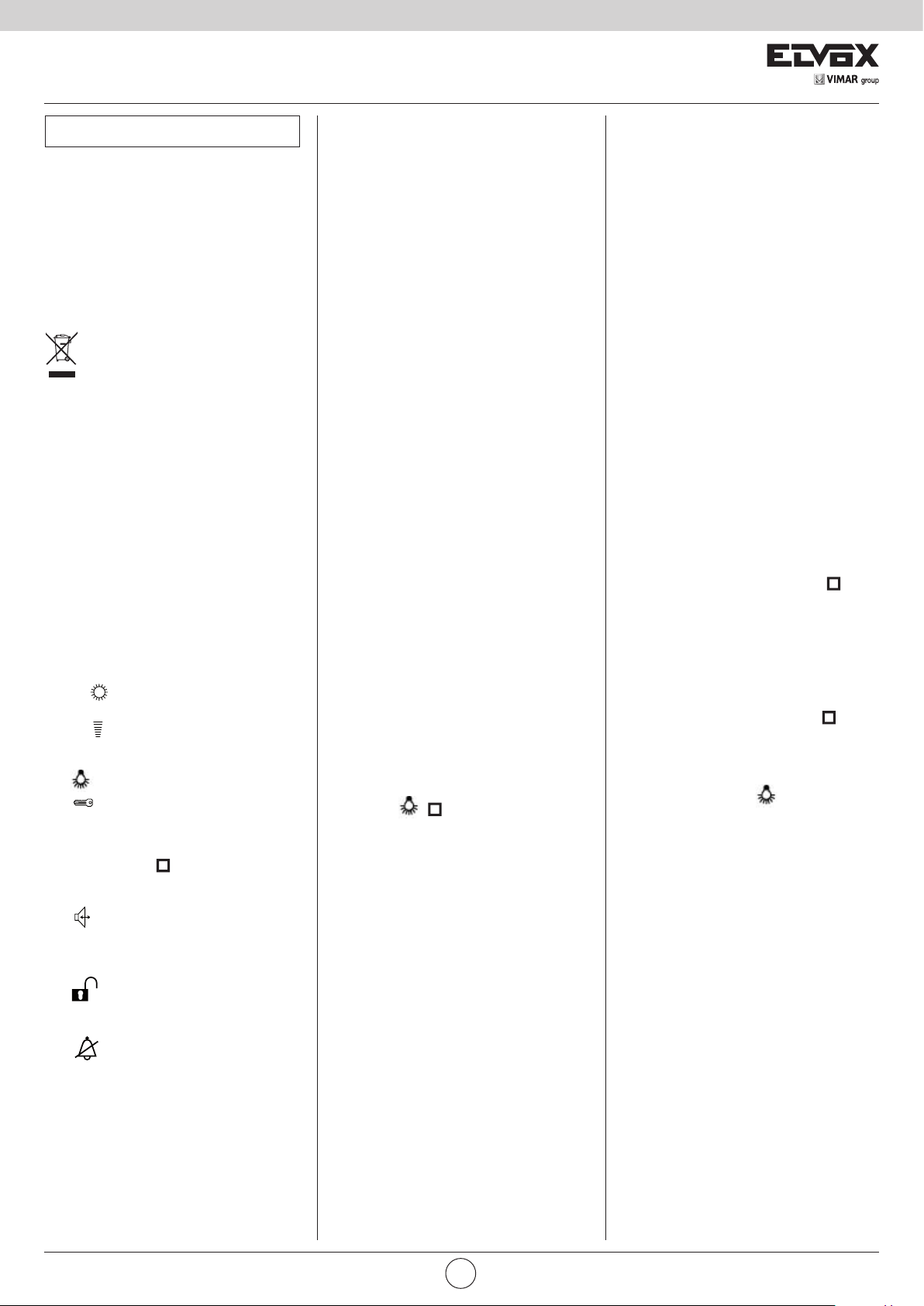
INSTALLAZIONE ART. 662D
- Fissare la borchia alla parete e inserire la presa
nella borchia
- Eseguire i collegamenti della morsettiera (vedi
schemi di collegamento).
INSTALLATION DES ART. 662D
- Die Buchse an die Wand befestigen un den
Halter in die Buchse einstecken.
- Das Klemmenbrett anchliessen (siehe Shaltplane)
Montaggio da esterno parete
Surface wall-mounting version
Version mural en saillie
Up-Wandmontage-Version
Versión de superficie
Versão montagem saliente
139
mm
INSTALLATION OF TYPE 662D
- Fix the monitor support to the wall and hook the
stud to the support.
- Connect the terminal block (see wiring diagrams).
INSTALACIÓN DEL ART. 662D
- Fijar la tachuela a la pared e insertar el soporte en
la tachuela.
- Conectar la regleta de conexiones (ver esquemas
de conexionado).
Fig. 5
4
1
2
3
INSTALLATION ART. 662D
- Fixer la bossette du moniteur à paroi et accrocher
le supporte a la bossette.
- Raccorder le bornier (voir schémas de raccordement)
INSTALAÇÃO DO ART. 662D
- Fixar abrocha à parede e inserir o suporte na
brocha.
- Efectuar as ligações da régua de bornes (ver
esquema de ligação)
141mm
40mm
12
PTESDEFRENIT
Page 13

141mm 125mm
6600
INSTALLAZIONE 6724
- Installare il videocitofono lontano da fonti
luminose e di calore.
- Fissare la piastra di aggancio del videocitofono
ad una altezza di 1,40m dal pavimento al bordo
inferiore.
- Eseguire i collegamenti della morsettiera (vedi
schemi di collegamento)
- Inserire il videocitofono seguendo il senso delle
frecce 1 e 2 (Fig. 5).
- Per togliere il videocitofono dalla piastra di aggancio, agire con un cacciavite sulla linguetta di sicurezza (posta sopra e dietro al videocitofono) ed
estrarlo seguendo il senso delle frecce 3 e 4.
INSTALLATION DES ART. 6724
- Das Videohaustelefon fern von Licht- und
Wärmequellen installieren.
- Die Befestigungsplatte des Monitors 1,40 m. in
Höhe vom Boden bis zu Unterkannt befestigen.
- Das Klemmenbrett anschliessen (siehe
Shaltpläne)
- Das Videohaustelefon durch folgender
Federrichtung 1 und 2 einstecken (Abb. 5).
- Um den Monitor aus der Befestigungsplatte zu
entfernen, mit einem Schraubenzieher auf die
Sicherheitfeder wirken (die sich auf der Oberseite
und hinten des Videohaustelefon) und durch
Folgen der Federrichtung 3 und 4 ihn ausziehen.
INSTALLATION OF TYPE 6724
- Install the video interphone away from sources of light and heat.
- Fix the monitor fixing plate at 1,40m. from the
ground level to the lower border.
- Connect the terminal block.
- Insert the monitor according to the 1 and 2 arrow
direction (Fig. 5).
- To remove the monitor from the plate hook, operate with a screw driver on the security lock (placed on the upper side and behind the monitor),
and remove it according to the 3 and 4 arrow
direction.
INSTALACIÓN DEL ART. 6724
- Instalar el videoteléfono lejos de fuentes luminosas y de calor.
- Fijar la placa de enganche del videoteléfono a
una altura de 1,40m desde el piso al borde inferior.
- Efectuar las conexiones de la regleta de conexiones (ver esquemas de conexionado).
- Insertar el videoteléfono siguiendo el sentido de
las flechas 1 y 2 (Fig. 5).
- Para quitar el monitor de la plancha de enganche, actuar con un destornillador sobre la lengüeta de seguridad (que se encuentra sobre y
detrás el videoteléfono) y extraerlo siguiendo el
sentido de las flechas 3 y 4.
INSTALLATION ART. 6724
- Installer le portier-vidéo loin de toutes sources de lumière et de chaleur.
- Fixer la plaque d’accrochage du moniteur à une
hauteur d’environ 1,40m du sol au bord inférieur.
- Effectuer les raccordements du bornier (voir
schémas de raccordement)
- Insérer le moniteur en suivant le sens des flèches
1 et 2 (Fig. 5).
- Pour enlever le moniteur de la plaque d’accrochage agir avec un tournevis sur la languette de
sécurité (placée) sur la partie supérieure et derrière le moniteur) et l’extraire suivant le sens des
flèches 3 et 4.
IINSTALAÇÃO DO 6724
Instalar o monitor afastado de fontes luminosas
ed de calor.
- Fixar a placa de encaixe do monitor a uma altura
de 1,40 m entre o pavimento e obordo inferior.
- Efectuar as ligações da régua de bornes (ver
esquema di ligação)
- Inserir o videotelefone seguindo o sentido das
setas 1 e 2 (Fig. 5).
- Para retirar o monitor da placa de encaixe, aplicar
uma chave de parafusos na lingueta de segurança (que fica sobre e detrás do videotelefone) e
extraí-lo seguindo o sentido das setas 3 e 4.
Montaggio da tavolo
Table version
Montage à encastrement
Tischversion
Versión de sobremesa
Versão de mesa
125
mm
Fig. 6
VIMAR group
PTESDEFRENIT
13
Page 14

6600
Sezione conduttori - Conductor section
Sections des conducteurs-Leiterquerchnitt
Secciones conductores-Secção condutores
Conduttori-Conductors Ø fino a 50m-Ø up to 50m Ø fino a 100m-Ø up to 100m Ø fino a 200m-Ø up to 200m Ø fino a 500m-Ø up to 500m
Conductors-Leitungslänge Ø jusqu’à 50m-Ø bis 50m Ø jusqu’à 100m.-Ø bis 100m Ø jusqu’à 200m.-Ø bis 200m Ø jusqu’à 500m.-Ø bis 500m
Conductores-Condutores Øhasta 50m - até 50m Ø hasta 100m - até 100m Ø hasta 200m - Ø até 200m Ø hasta 500m - Ø até 500m
4, 5, 9.10 0,75 mm² 1 mm² 1,5 mm² 4mm²
- + 15, 0 ,S1 serratura, - + lock
- + 15, 0 ,S1 gâche, - + Türöffner 1 mm² 1,5 mm² 2,5 mm² -
- + 15, 0 ,S1 cerradura, - + trinco
Altri-Others-Autres
Andere-Otros-Outros 0,5 mm² 0,75 mm² 1 mm² 2,5mm²
Video Cavo coassiale 75 Ohm (tipo RG59) o RG11 a doppio isolamento
Video 75 Ohm coaxial cable (type RG59) or RG11 double insulation
Vidéo Câble coaxial 75 Ohm (type RG59) ou RG11 à double isolation
Video 75 Ohm Koaxialkabel (RG59) oder RG11 mit Doppelisolation
Vídeo Cable coaxial de 75 Ohm (tipo RG59 o RG11 com doble aislamiento)
Vídeo Cabo coaxial de 75 Ohm (tipo RG59) ou RG11 duplo isolamento.
N.B.
All’alimentatore Art. 6948 si possono collegare fino a 18 monitor Art.
6624, 662D, 6724 con la funzione “chiamata esclusa” attiva (LED rosso
acceso).
Per collegare dei monitor aggiuntivi utilizzare l’alimentatore
supplementare Art. 6942.
Note:
Up to 18 monitors type 6624, 662D, 6724 with the “call excluded”
function activated (red LED switchbed on) can be connected to power
supply type 6948. To connect additional monitors use additional power
supply type 6942.
N.B.
À l’alimentation Art. 6948 on peut connecter jusqu’à 18 moniteurs Art.
6624, 662D, 6724 avec la fonction “appel exclu” active (LED rouge
allumée).
Pour raccorder des moniteurs supplémentaires utiliser l’alimentation
supplémentaire Art. 6942.
HINWEIS:
Am Netzgerät Art. 6948 können bis zu 18 Monitoren Art. 6624,
662D, 6724 mit der “Ruf ausgenommen”-Funktion activ (rote LED
angeschaltet) angeschlossen werden. Um Zusatzmonitoren
anzuschliessen, Zusatznetgerät Art. 6942 verwenden.
N.B.
Al alimentador Art. 6948 se pueden conectar hasta 18 monitores Art.
6624, 662D, 6724 con la función de “llamada excluída” activa (LED rojo
encendido). Para conectar monitores adicionales utilizar el alimentador
suplementar Art. 6942.
N.B.
Ao alimentador Art. 6948 podem-se ligar até 18 monitores Art. 6624,
662D, 6724 com a função de “chamada excluida” activa (LED vermelho
aceso). Para ligar alguns monitores suplementares utilizar o alimentador
suplementar Art. 6942.
D1- Targa per videocitofono
Video-intercom panel
Plaque de rue pour portier-vidéo
Video-Türsprechstelle
Placa para vídeo-portero
Telecâmara botoneira
Art. 8845/C
D2- Targa per videocitofono
Video-intercom panel
Plaque de rue pour portier-vidéo
Video-Türsprechstelle
Placa para vídeo-portero
Telecâmara botoneira Art. 8847/C
P- Pulsante supplementare serratura
Additional push-button for lock
Poussoir supplémentaire gâche
zusätzliche Türöffnertaste
Pulsador suplementario cerradura
Botão suplementar de trinco
L- Serratura elettrica-Electric lock
Gâche électrique-Elektrischer Türöffner
Cerradura eléctrica-Trinco eléctrico 12V ~
E1- Morsettiera di collegamento
Connection terminal block
Bornier de raccordement
Anschlussklemmenbrett
Regleta de conexión
Régua de ligação
E2- Unità elettronica
Electronic unit
Unité électronique
Elektronische Einheit
Unidad electrónica
Unidade electrónica
14
E3- Moduli supplementari serie 8A...
Additional modules range 8A.
Modules supplémentaires série 8A..
Zusatzmodule baureihe 8A...
Módulos suplementarios serie 8A...
Módulo suplementares da série 8A...
PTESDEFRENIT
Page 15

-
+
4 5 3 V 1
6600
DIGITAL DOOR ENTRY AND VIDEO SYSTEMS FOR CONDOMINIUM WITH MONITORS AND INTERPHONES WITH AN INTERNAL DECODING FACILITY.
IMPIANTO CONDOMINIALE VIDEOCITOFONICO DIGITALE CON MONITOR E CITOFONI CON DECODIFICA INTERNA.
INSTALLATION DE PORTIER-VIDÉO DIGITAL DE COPROPRIETÉ AVEC MONITEURS ET POSTES D’APPARTEMENTS AVEC DECODAGE INTERNE.
DIGITALVIDEOTÜRSPRECHANLAGE FÜR MEHRFAMILIENHÄUSERN MIT MONITOREN UND HAUSTELEFONEN MIT DEKODIERUNG.
INSTALACIÓN CONDOMINIAL DE VÍDEO PORTERO CON MONITORES E INTERFONOS CON DECODIFICACIÓN NTERNA.
INSTALAÇÃO DE CONDOMÍNIO PARA PORTEIRO DIGITAL VIDEO COM MONITORES E INTERFONES EQUIPADOS COM INTERNO.
MONTANTE MONITOR - MONITOR CABLE RISER
MONTANT MONITEUR - MONITORSTEIGLEITUNG
COLUNA MONTANTE DE MONITORES
*
In ogni monitor inserire
tra i morsetti V-M la
resistenza di 75 Ohm
fornita in dotazione.
Connect 75 Ohm
resistor (supplied) in
each monitor, between
terminals V-M.
Raccorder dans
tous les moniteurs la
résistance de 75 Ohms
fournie entre les bornes
V-M.
Bei allen Monitoren
zwischen Klemmen
V-M den mitgelieferten
75 Ohm
Abschlusswiderstand
montieren.
Montar la resistencia de
75 Ohm suministrada
de serie entre los
bornes V-M en cada
monitor.
Em cada monitor inserir
a resistência de 75
Ohm fornecida entre os
bornes V-M.
MONITOR COLORI
COLOUR MONITOR
MONITEUR COULEURS
FARBMONITOR
MONITOR A COLORES
MONITOR CORES
Art. 6624
Art. 6724
Art. 662D
MONITOR COLORI
COLOUR MONITOR
MONITEUR COULEURS
FARBMONITOR
MONITOR A COLORES
MONITOR CORES
Art. 6624
Art. 6724
Art. 662D
DISTRIBUTORE
DISTRIBUTOR
DISTRIBUTEUR
VERTEILER
DISTRIBUIDOR
Art. 5556/004
Art. 5555
V3
M
V1
*
13
12
11
10
9
8
7
6
5
4
3
2
1
V3
75ohm 75ohm
M
V1
13
12
11
10 10
9
8
7
6
5
4
3
2
1
V4
V3
V2
V1
V
V
-
+
RETE-NETWORK
- + 3 4 5 V 1
RÉSEAU-NETZ
RED-REDE
PRI
M2 V2 V1 M1 S1
V3
75ohm 75ohm
M
V1
13
12
11
10
9
8
7
6
5
4
3
2
1
V3
M
V1
13
12
11
9
8
7
6
5
4
3
2
1
Art. 6948
+I
MONITOR COLORI
COLOUR MONITOR
MONITEUR COULEURS
FARBMONITOR
MONITOR A COLORES
MONITOR CORES
Art. 6624
Art. 6724
Art. 662D
MONITOR COLORI
COLOUR MONITOR
MONITEUR COULEURS
FARBMONITOR
MONITOR A COLORES
MONITOR CORES
Art. 6624
Art. 6724
Art. 662D
R1
ALIMENTATORE
4
POWER SUPPLY
R2
ALIMENTATION
4
-
NETZGERÄT
O 15 + 5 4 3 F2 F1 S CH
ALIMENTADOR
VIMAR group
88888888
1
4
7
R
M
V
1
3
4
5
6
8
V1
M1
DO
V2
SR
+I
CH
VL
3
2
6
5
*
9
8
C
0
J1
4
F1
F2
+L
SR
CH
V
1
3
4
5
D DO
+I
J1
M
V
1
3
4
5
6
8
V1
M1
D
V2
SR
+I
CH
VL
4
F1
F2
+L
SR
CH
V
1
3
4
5
+I
P
L
PTESDEFRENIT
N° SI205
15
Page 16

75ohm
1V543+-
-+345V1
PRI
012
10
5
2
1
4
3
7
6
9
8
M
12
11
13
V1
V3
F2
K
P
L
1
2
4
6
5
F1
3
F
R
75ohm
V3
V1
13
11
12
M
8
9
6
7
3
4
1
2
5
10
-+345V1
PF
6600
VARIANTE-VERSION-SONDERSCHALTUNG-VARIACIÓN 1
Variante di collegamento per monitor Art. 6624 con
pulsante chiamata fuoriporta.
Variation of wiring diagram for monitor type 6624
with push-button for outdoor call.
Variation de raccordement pour moniteur Art. 6624
avec bouton-poussoir pour appel porte palière.
Sonderschaltung für Monitor Art. 6624 mit Taste
für Wohntürruf.
Variación de conexionado para monitor Art. 6624
con pulsador para llamada puerta apartamiento.
Variante de ligação para monitor Art. 6624 com
botão para chamada no patamar.
V3
75ohm
M
V1
Monitor
Moniteur
Art. 6624
Art. 6724
Art. 662D
13
12
11
10
9
8
7
6
5
4
3
2
1
K
K- Pulsante fuori porta
Outdoor push-button
Poussoir à la porte de l’appartement
Wohnungstür-Klingelknopf
Pulsador puerta apartamiento
Botão de patamar
F- Targa audio secondaria
Secondary audio entrance panel
Plaque de rue audio sécondaire
Audio-Nebenklingeltableau
Placa audio secundaria
Botoneira audio secundária
F1- Gruppo fonico Art. 930D
Speech unit type 930D
Poste externe audio Art. 930D
Audio-Außenstelle Art. 930D
Aparato externo audio Art. 930D
Posto externo audio Art. 930D
PF- Pulsante per apertura serratura fuori porta
Push-button for the outdoor lock opening.
Bouton-poussoir pour ouverture de la gâche porte palière.
Taste für die Öffnung des Wohntürschlosses.
Pulsador para la abertura de la cerradura puerta apartamiento.
Botão para a abertura do trinco no patamar.
L- Serratura elettrica-Electric lock
Gâche électrique-Elektrischer Türöffner
Cerradura eléctrica-Trinco eléctrico 12V ~
P- Pulsante supplementare serratura
Additional push-button for lock
Poussoir supplémentaire gâche
zusätzliche Türöffnertaste
Pulsador suplementario cerradura
Botão suplementar de trinco
F2- Lampada luce targa
Bulb for panel lighting
Lampe d’éclairage plaque
Birne für Tastenbeleuchtung
Lámpara luz escalera
Lâmpada da luz da botoneira
(3x24V 3W max.)
10x24V 3W con/with Art. M832
16X24V 3W con/with Art. 0832/030
Variante di collegamento per monitor Art. 6624 o con targa
citofonica fuoriporta con posto esterno Art. 930D
Variation of wiring diagram for monitor type 6624 or with
outdoor audio entrance panel with speech unit type 930D.
Variation de raccordement pour moniteur Art. 6624 ou avec
plaque audio porte palière avec poste externe Art. 930D.
Sonderschaltung für Monitor Art. 6624 oder mit AudioWohnklingeltableau mit Außenstelle Art. 930D.
Variación de conexionado para monitor Art. 6624 o con placa
audio puerta apartamiento con aparato externo Art. 930D.
Variante de ligação para monitor Art. 6624 ou com botoneira
audio no patamar com posto externo Art. 930D.
MONTANTE MONITOR
MONITOR CABLE RISER
MONTANT MONITEUR
MONITORSTEGLEITUNG
MONTANTE MONITOR
COLUNA MONTANTE PARA OS MONITORES
V3
75ohm
M
V1
Monitor
Moniteur
Art. 6624
Art. 6724
Art. 662D
13
12
11
10
9
8
7
6
5
4
3
2
1
PF
Rete
Mains
Réseau
Netz
Red
Rede
PRI
120
F
R
F2
K
F1
1
2
3
4
5
6
Trasformatore
Transformer
Transformateur
Transformator
Transformador
Art. M832
P
L
1V543+-
MONTANTE MONITOR
MONITOR CABLE RISER
MONTANT MONITEUR
MONITORSTEGLEITUNG
COLUNA MONTANTE PARA OS MONITORES
MONTANTE MONITOR
-+345V1
N° SI206
16
PTESDEFRENIT
Page 17

+U
-B
1V3 54
+
-
6600
VARIANTE-VERSION-SONDERSCHALTUNG-VARIACIÓN 2
N° SI210
COLUNA MONTANTE PARA OS MONITORES
Lo schema illustra il collegamento della segnalazione di serratura
aperta (LED verde) con monitor Art. 6624, 662D, 6724 (collegamento
al morsetto 11).
Se si collegano fino a 5 monitor, non è necessario utilizzare l’alimentatore Art. 6582, ma è sufficiente utilizzare il morsetto “+” del 6948
per alimentare il led verde. Per escludere la segnalazione di serratura
aperta non collegare il morsetto N. 11 dei monitor.
La segnalazione di suoneria esclusa è già inserita nei monitor e non
serve collegare nessun conduttore supplementare.
I LED rossi sono alimentati dall’alimentatore 6948 che può alimentare
massimo 18 e non devono essere in totale più di 20. Oltre tale numero
ricorrere ad un alimentatore supplementare.
The diagram shows the connection of the “lock open” indicator (green
LED) with monitor Art. 6624, 662D, 6724 (connection to terminal 11).
Should up to 5 monitors be connected, it is not necessary the use of
power supply Art. 6582, but it is sufficient to use terminal “+” of power
supply type 6948 to power the green led. To disable the “lock open”
indication, do not connect terminal No 11 of the monitors. The ringtone
OFF indication is already inserted in the monitors and it is not necessary to connect any additional conductor.
The red LEDs are powered by the power supply 6948 and must not
exceed a total of 18 in number. For larger numbers, use an additional
power supply.
MONTANTE MONITOR
MONITOR CABLE RISER
MONTANT MONITEUR
MONITORSTEGLEITUNG
MONTANTE MONITOR
V3
75ohm
M
V1
Monitor
Moniteur
Art. 6624
Art. 6724
Art. 662D
13
12
11
10
9
8
7
6
5
4
3
2
1
Collegamento variante porta aperta con led verde.
Variation of wiring diagram for “open door” mit green led.
Raccordement variante “porte ouverte” avec led verte.
Anschluss für die “Geöffnete tür”-sonderschaltung mit grüner led.
Conexionado variación “puerta abierta” con led verde.
Ligação variante “porta aberta” com led verde.
Alimentatore-Power supply
Alimentation-Netzgerät
Alimentador Art. 6582
Rete
Mains
Réseau
Netz
+U
-+345V1
Red
Rede
PRI
Alimentatore-Power supply
Alimentation-Netzgerät
Alimentador Art. 6948
CH SF1F2 345+150
+I
-
S1M1V1V2M2
Rete
Mains
Réseau
Netz
Red
Rede
R1
R2
PRI
4
4
D+U
AC+I
M
88888888
1
4
7
R
V
1
3
4
5
6
8
V1
M1
DO
V2
SR
+I
CH
VL
3
2
6
5
*
9
8
C
0
J1
4
F1
F2
+L
SR
CH
V
1
3
4
5
Le schéma représente le raccordement de la
signalisation de gâche ouverte (LED verte)
avec moniteur Art. 6624, 662D, 6724 (raccor
dement à la borne 11).
-
Si on raccorde jusqu’à 5 moniteurs, il n’est
pas nécessaire d’utiliser l’alimentation Art.
6582, mais il est suffisant d’utiliser la borne «
+ » de l’alimentation Art. 6948 pour alimenter
la led verte.Pour exclure la signalisation de
gâche ouverte, ne pas connecter le borne N.
11 des moniteurs.
La signalisation de sonnerie exclue est déjà
prévue dans les moniteurs si bien qu’acun
conducteur supplémentaire ne doit être rac
cordé.
Les LED rouges sont alimentées par l’alimen
tation 6948, leur nombre max étant de 18 et il
ne peut y en avoir au total plus de 20. Au-delà
de ce nombre, il faudra installer des alimenta
tions supplémentaires.
-
-
-
VIMAR group
M
V
1
3
4
5
6
8
V1
J1
M1
D
V2
SR
+I
CH
VL
4
F1
F2
+L
DDO
Auf dem Plan ist der Anschluss der Anzeige
„Tür offen”
(grüne LED) an Monitor Art. 6624, 662D,
6724 (Anschluss an Klemme 11) dargestellt.
Soll bis zu 5 Monitoren verwendet werden,
so ist es nicht notwendig das Netzgerät Art.
6582 zu verwenden, ist es aber genug die
Klemme „+“ des Netzgeräts Art. 6948 zu ver
wenden um die grüne Led zu versorgen. Um
-
die Anzeige „Tür offen” auszuschließen, die
Monitorklemme Nr. 11 nicht anschließen.
Die Anzeige für Ruftonabschaltung ist bereits
in den Monitor integriert, es muss kein weite
rer Leiter angeschlossen werden.
-
Die roten LEDs (max. 18) werden vom
Netzgerät 6948. Darüber hinaus ist ein
zusätzliches Netzgerät erforderlich.
V
1
3
4
5
SR
+I+I
CH
F1
F2
El esquema ilustra la conexión de la señalización de cerradura abierta (LED verde) con
monitor Art. 6624, 662D, 6724 (conexión al
borne 11).
Si se conectan hasta 5 monitores, no es
necesario utilizar el alimentador Art. 6582,
mas es suficiente utilizar el borne “+” del
alimentador Art. 6948 para alimentar el led
verde.
Para excluir la señalización de cerradura
abierta, no hay que conectar el borne N. 11
de los monitores.
La señalización de timbre excluido ya se ha
conectado en los monitores y no es necesario
conectar ningún conductor suplementario.
Los leds rojos se alimentan mediante el ali
mentador 6680, y, cómo máximo, puede
-
haber 18. Si se supera dicho número, se
debe emplear un alimentador suplementario.
PTESDEFRENIT
P
L
O esquema refere-se à ligação da sinalização
de trinco aberto (LED verde) com monitores
Art. 6624, 662D, 6724 (ligação ao borne 11).
Se se ligarem até 5 monitores, não é neces
sário utilizar o alimentador Art. 6582, mas è
suficiente utilizar o terminal “+” do alimentador
Art. 6948 para alimentar o led verde. Sem
sinalização de trinco aberto não é ligado o
borne N. 11 dos monitores
A sinalização de campainha excluída é uma
função inserida nos monitores, pelo que não
serve ligar condutores suplementares aos
esquemas base.
Os LEDs vermelhos são alimentados pelo
alimentador 6680 e não devem ser no total
mais de 18. Para valores superiores deve-se
recorrer a um alimentador suplementar.
17
-
Page 18

75ohm
25
V3
6600
VARIANTE-VERSION-SONDERSCHALTUNG-VARIACIÓN 3
Collegamento suonerie supplementari a timpano con monitor muniti di decodifica interna.
Si possono collegare suonerie supplementari funzionanti a 12V c.a. utilizzando il relè Art. 0170/101 collegandolo come da schema. Portata dei contatti 3A-250V.
Supplementary membrane bell connection for monitors without internal decoding.
12V A.C. additional bells can be fitted using the relay Art. 0170/101 connected as shown in the diagram.
Contact rating 3A - 250V
Raccordement sonneries supplémentaires à timbre avec moniteurs équipés du décodage interne.
On peut raccorder des sonneries supplémentaires en 12V c.a. avec le relais Art. 0170/101 raccordé suivant le schéma.
Portée des contacts 3A-250V.
Anschluß zusätzlicher Läutwerke an Monitoren mit interne Decodierung.
Es ist möglich, zusätzliche 12V AC Lautwerke zu installieren, in dem das Relais Art. 0170/101 gemäß Schema angeschlossen wird. Stromfestigkeit der Kontakte 3A-250V
Conexionado timbres suplementarios con monitores provistos de codificación interna.
Se pueden conectar timbres suplementarios funcionantes con 12V c.c. utilizando el relé Art. 0170/101 conectándolos como desde esquema. Capacidad de los contactos 3A-250V.
Ligação das campaínhas suplementares com monitores com descodificador interno.
Podem-se ligar campaínhas suplementares funcionando a 12V c.a. utilizando o relé Art. 0170/101, ligando-o como mostra o esquema. Carga nos contactos 3 A-250 V.
N° SI208
M
V1
13
12
Monitor
Moniteur
Art. 6624
Art. 6724
Art. 662D
11
10
9
8
7
6
5
4
3
2
1
Relè - Relay - Relais
Art. 170/101
Alimentazione suoneria
Bell supply
Alimentation sonnerie
Versorgung des Läutwerks
Alimentación timbre
Alimentação da campainha
N.B.
Se vengono collegate suonerie supplementari con elevato assorbimento effettuare anche il collegamento tra i morsetti RC-4 del relè Art. 0170/101.
If additional bells with high absorption are fitted, also connect terminals RC-4 of relay Art. 0170/101.
Si on raccorde des sonneries supplémentaires ayant une absorption élevée, effectuer également le raccordement entre les bornes RC-4 du relais Art. 0170/101.
Bei Anschluß zusätzlicher Läutwerke mit hoher Stromaufnahme auch die Klemmen RC-4 des Relais Art. 0170/101 verbinden.
Si se conectan timbres suplementarios con elevada absorción efectuar también el conexionado entre los bornes RC-4 del relé Art. 0170/101.
Se forem utilizadas campaínhas suplementares com elevado consumo efectuar, também, a ligação entre os bornes RC-4 do relé Art. 0170/001.
+
-
1C
Suoneria
Bell
Sonnerie
Läutwerk
Timbre
Campainha
12V c.a./~
RC
34
15
18
PTESDEFRENIT
Page 19

ON
6600
VARIANTE-VERSION-SONDERSCHALTUNG-VARIACIÓN 4
N° SI207
V3
75ohm
M
V1
Monitor
Moniteur
Art. 6624
Art. 6724
Art. 662D
13
12
11
10
9
8
7
6
5
4
3
2
1
453V1
1V543+-
-
MONTANTE MONITOR
+
MONITOR CABLE RISER
MONTANT MONITEUR
MONITORSTEGLEITUNG
MONTANTE MONITOR
COLUNA MONTANTE PARA OS MONITORES
Rete-Mains
Réseau-Netz
Red-Rede
PRI
M2 V2 V1 M1 S1
+I
Alimentatore
Power supply
Alimentation
Netzgerät
Alimentador
Art. 6948
R1
4
R2
4
-
O15+543F2F1SCH
Relè - Relay - Relais
Art. 0170/001
Relè - Relay - Relais
Art. 0170/001
12345 54321
88888888
1
2
5
4
8
7
0
R
M
V
1
3
4
5
6
8
V1
M1
DO
V2
SR
+I
CH
VL
3
6
*
9
C
4
J1
F1
F2
+L
V
1
3
4
5
DDO
SR
CH
Collegamento funzione ausiliaria F1-F2 in impianti
videocitofonici muniti di decodifica interna.
È possibile l’attivazione di una funzione ausiliaria F1
comandata dai monitor collegando un relè Art. 0170/001
come da schema (morsetti R1-4 dell’alimentatore). Per la
funzione ausiliaria F2 inserire un relè Art. 0170/001 e
collegarlo ai morsetti R2-4 dell’alimentatore. Il tasto “
del monitor attiva la funzione F1. Il tasto “
” del monitor
attiva la funzione “F2”.
M
V
1
3
4
5
6
8
V1
M1
D
V2
SR
+I
CH
VL
4
J1
F1
F2
+L
V
1
3
4
5
SR
+I+I
CH
F1
F2
Connecting additional function F1-F2 to video door
entry systems with internal decoding.
An additional monitor controlled function F1 can be
activated by connecting relay Art. 0170/001 as per
diagram (terminals R1-4 of the power supply). For the F2
auxiliary function insert a relay type 0170/001 and connect
it to the power supply terminals R2-4. Monitor push-button
”
” activates the F1 function. Monitor push-button “ ”
“
activates the F2 function.
CN
OC
Funzione supplementare “F1” e “F2”
“F1”, “F2” additional function
Fonction supplémentaire “F1” et “F2”
“F1” und “F2” zusätzliche Funktion
Función suplementaria “F1”, “F2”
Função suplementar “F1”, “F2”
P
L
Connexion de la fonction auxiliaire F1-F2 dans des
installations portiers vidéo équipés du décodage
interne. On peut activer une fonction auxiliaire (F1)
commandée par les moniteurs en reliant un relais
Art. 0170/001 selon le schéma (bornes R1-4 de
l’alimentation). Pour la fonction auxiliaire F2 insérer un
relais Art. 0170/001 et le connecter aux bornes R2-4 de
l’alimentation.
Le bouton-poussoir “
F1. Le bouton-poussoir “
” du moniteur active la fonction
” du moniteur active la
fonction F2.
Anschluß der Zusatzfunktion F1-F2 an VideoTürsprechanlagen mit interner Decodierung.
Es ist möglich, eine über den Monitor gesteurte
Zusatzfunktion (F1) zu aktivieren, indem ein Relais Art.
0170/001 gemäß Schema angeschlossen wird (Klemmen
R1-4 des Netzgeräts). Für die Zuzatsfunktion F2 ein
Relais Art. 0170/001 einsetzen und es an Klemmen R2-4
des Netzgerats anschließen. Monitorstaste “
die F1 Funktion. Monitorstaste “
” aktiviert
” aktiviert die F2
Funktion
VIMAR group
Conexionado función auxiliares F1-F2 en
instalaciones con vídeo portero provistos de
codificación interna.
Es posible la activación de una función auxiliar (F1)
mandada por los monitores conectando un relé Art.
0170/001 como de esquema (bornes R1-4 del
alimentador). Para la function ausiliar F2 insertar un relé
Art. 0170/001 y conectarlo a los bornes R2-4 del
alimentador. El pulsador “
función F1. El pulsador “
” del monitor activa la
” del monitor activa la función
F2
PTESDEFRENIT
Ligação das funções auxiliares F1 - F2 em instalações
de video-porteiro equipadas com descodificador
interno.
É possível a activação de uma função auxiliar (F1)
comandada do monitor ligando um relé Art. 0170/001
como mostra o esquema (bornes R1-4 do alimentador).
Para a função auxiliar F2 inserir um relé Art. 0170/001 e o
ligar aos terminais R2-4 do alimentador. O botão “
monitor ativa a função F1. O botão “
” do
” do monitor
ativa a função F2.
19
Page 20

S6I.660.400 06 1702
Viale Vicenza, 14
36063 Marostica VI - Italy
www.vimar.com
 Loading...