

Page 1
Guida rapida - Quick Guide - Guide rapide
Guía rápida - Kurzanleitung - Guia de consulta rápida
Σύντομος οδηγός
TAB 7
40607
Videocitofono TAB 7S IP vivavoce
TAB 7S IP hands-free video entryphone
Portier-vidéo TAB 7S IP mains libres
Videoportero TAB 7S IP manos libres
Freisprech-Videohaustelefon TAB 7S IP
Videoporteiro TAB 7S IP alta-voz
Θυροτηλεόραση ανοικτής ακρόασης TAB 7S IP
40607_49400925a0_Quik Guide_01.indd 1 27/09/2017 16:39:01
Page 2
TAB: 40607
IT
Il manuale istruzioni è scaricabile dal sito www.vimar.com
Descrizione
Videocitofono vivavoce da parete per sistema IP con display a colori LCD touch-screen, tastiera capacitiva per funzioni citofoniche e chiamate intercomunicanti, teleloop per protesi acustiche, staffa per il fissaggio su scatola rettangolare o rotonda.
Caratteristiche tecniche
• Display 7 pollici, 800x480, 16M colori.
• Touchscreen + 2 tasti capacitivi retroilluminati.
• Vivavoce full-duplex con echo canceller e funzione teleloop.
• Montaggio: a parete, con staffa metallica, su scatola: circolare 2M (Vimar V71701), 3M (Vimar V71303, V71703) orizzon
tale e verticale, 4+4M (Vimar V71318, V71718) e quadrata British standard.
• E’ possibile l’installazione in versione da tavolo mediante l’accessorio base da tavolo 40195.
• Dimensioni: 166 x 184 x 24.2 (a parete).
• Alimentazione: PoE, classe 0.
• Consumo tipico PoE: 8 W
• Temperatura di funzionamento: -5 ÷ 40 °C.
Funzioni principali
• Ricezione video chiamate da posto esterno.
• Autoaccensione posto esterno.
• Apertura serratura posto esterno.
• Chiamate audio intercomunicanti.
• Trasferimento di chiamata.
• Attivazione attuazioni d’impianto (luce scale, funzioni ausiliarie).
• Rubrica d’impianto e menu preferiti per accesso veloce.
• Video-segreteria configurabile.
• Ricezione e invio di messaggi di testo.
• Suonerie multiple configurabili tra quelle disponibili nel dispositivo.
• Regolazioni audio e video in chiamata.
• Ingresso per campanello fuori porta.
• Supporto per integrazione TVCC IP.
• Supporto per servizio di chiamata remota su smartphone/tablet tramite connettività Wi-Fi.
-
Funzione di audiofrequenza per protesi acustiche (teleloop)
Il videocitofono è utilizzabile da parte dei portatori di protesi acustiche.
Per un corretto funzionamento dell’apparecchio acustico, fare riferimento al relativo manuale di istruzioni. La presenza di og
getti metallici o apparecchi elettronici, può compromettere la qualità del suono percepito sull’apparecchio acustico.
-
Manutenzione
Eseguire la pulizia utilizzando un panno morbido. Non versare acqua sull’apparecchio e non utilizzare alcun tipo di prodotto
chimico.
Avvertenze per l’utente
Non aprire o manomettere l’apparecchio.
In caso di guasto avvalersi di personale specializzato.
2
40607_49400925a0_Quik Guide_01.indd 2 27/09/2017 16:39:01
Page 3

TAB: 40607
IT
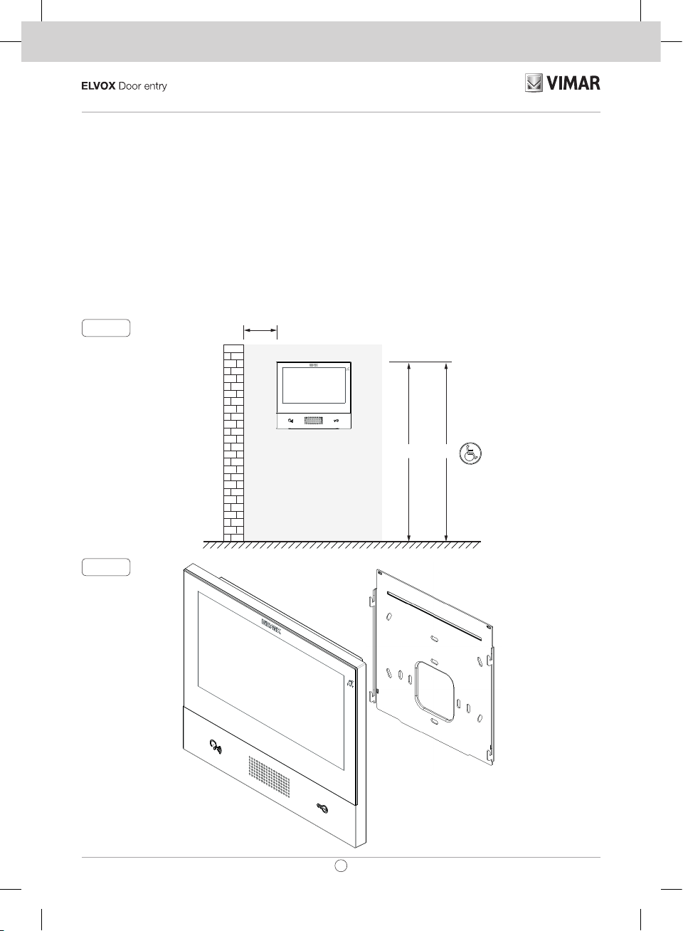
Installazione
Importante: Si consiglia di installare il dispositivo ad un’altezza di circa 160 cm dal pavimento facendo attenzione a non
esporlo a fonti dirette di illuminazione in modo da evitare fastidiosi fenomeni di riflessione sulla superficie dello schermo LCD.
Nota: in fig. 1 le misure di installazione consigliate, salvo diverse indicazioni della normativa locale vigente in materia.
1. Fissare la piastra a parete, con staffa metallica, su scatola: circolare 2M (Vimar V71701), 3M (Vimar V71303, V71703)
orizzontale e verticale, 4+4M (Vimar V71318, V71718) e quadrata British standard.
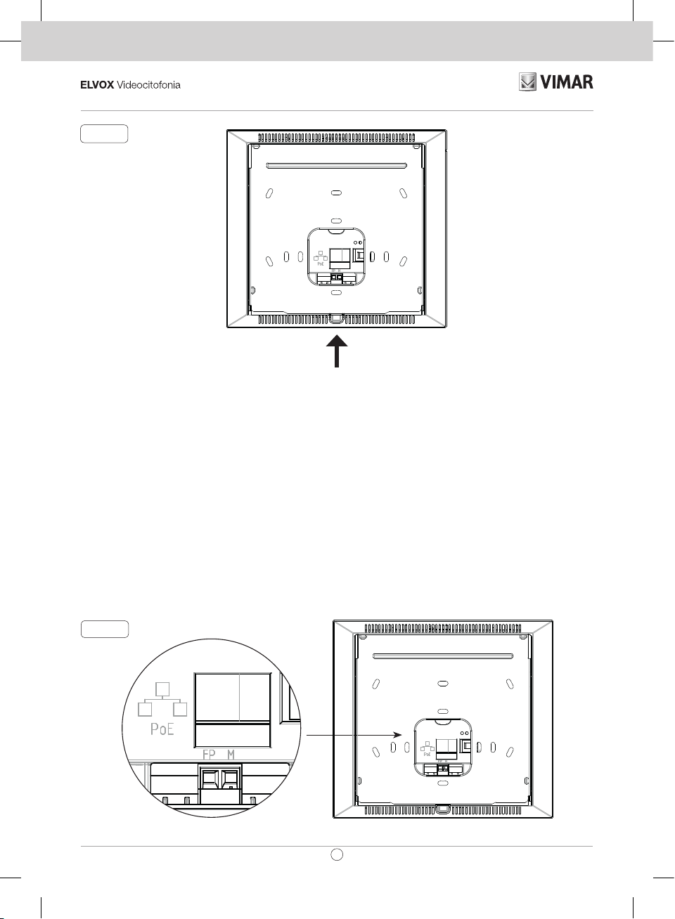
2. Collegare il PLUG RJ45 della rete videocitofonica e se presente pulsante fuoriporta cablare la morsettiera FP - M (fig. 6).
3. Alloggiare il videocitofono nel seguente modo: posizionare il videocitofono sulla piastra tenendolo leggermente sollevato, a
questo punto tenendo premuto il frontale fare una leggera pressione verso il basso fino all’aggancio.
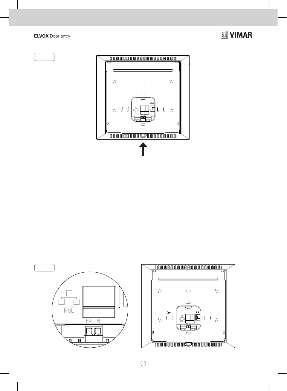
4. Nel caso in cui fosse necessario togliere il videocitofono è necessario agire facendo una leggera pressione nell’apposita
levetta (Fig. 3) e sollevare (dal basso verso l’alto) in modo da sganciare il videocitofono dal telaio.
Fig. 1
Fig. 2
> 10 cm
1,20m1,60 / 1,65m
3
40607_49400925a0_Quik Guide_01.indd 3 27/09/2017 16:39:02
Page 4
TAB: 40607
IT
Fig. 3
Interfacce e morsetti
• PoE: interfaccia RJ45 Ethernet 10/100 Mbps, PoE classe 0.
• FP: Ingresso NO per contatto pulito, pulsante chiamata fuoriporta (riferimento al morsetto M).
• M: Riferimento massa per pulsante fuoriporta.
Indicazioni di installazione:
• L'interfaccia di rete RJ45 va collegata esclusivamente ad una rete SELV (Safety Extra-Low Voltage).
• L'alimentatore PoE (Power-over-Ethernet PSE, Power Sourcing Equipment) deve fornire isolamento elettrico tra qualsiasi
conduttore accessibile incluso il conduttore di terra, se esistente, e tutti i contatti delle porte di rete, inclusi quelli inutilizzati
dal PSE o dal dispositivo da installare.
Fig. 6
4
40607_49400925a0_Quik Guide_01.indd 4 27/09/2017 16:39:02
Page 5
TAB: 40607
IT
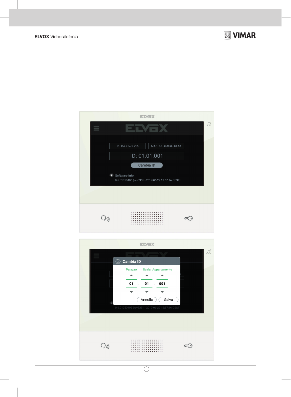
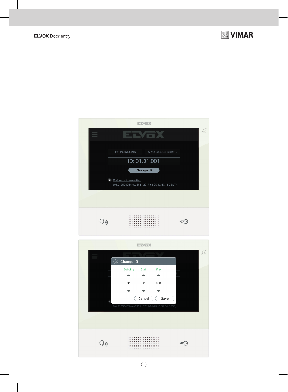
Prima accensione
Il dispositivo, opportunamente cablato e alimentato, presenta, quando non congurato, la seguente schermata su cui sono
indicati: indirizzo IP (automatic link-local address temporaneo), indirizzo MAC, identicativo d’impianto, versione rmware. Di
default, tutti i dispositivi hanno ID 00.00.000 ovvero identicativo non specicato: per semplicare l’attività di congurazione
d’impianto tramite Video Door IP Manager, l’installatore può impostare l’ID su ciascun dispositivo. Premere Change ID e nella
schermata successiva assegnare l’identicativo: selezionare un ID univoco per ciascuna utenza; assegnare lo stesso ID a tutti
i videocitofoni appartenente alla stessa utenza.
Nel caso di installazione di un KIT, l'impostazione dell'ID è ininuente: seguire le istruzioni nel capitolo successivo per l'attivazione
del KIT. Viceversa, l'installatore deve completare la congurazione e attivazione del dispositivo tramite il software Video Door
IP Manager (fare riferimento alla documentazione relativa a VDIPM).
5
40607_49400925a0_Quik Guide_01.indd 5 27/09/2017 16:39:03
Page 6
TAB: 40607
Installazione KIT
Alimentare i dispositivi del KIT, ad esempio TAB 7S IP (art. 40607) e unità IP A/V (art. 41006), collegandoli alla stessa rete,
e attendere che sul display venga visualizzata la schermata iniziale precedentemente descritta. Premere sull'icona Menu
nell'angolo in alto a sinistra e selezionare l'opzione di con gurazione KIT. Completare i passi (impostazioni lingua e data/ora)
e attendere il completamento della procedura: al termine il dispositivo si riavvia in modalità operativa.
In caso venga noti cato un errore sullo schermo, veri care che tutti i dispositivi siano opportunamente collegati e alimentati
e riprovare.
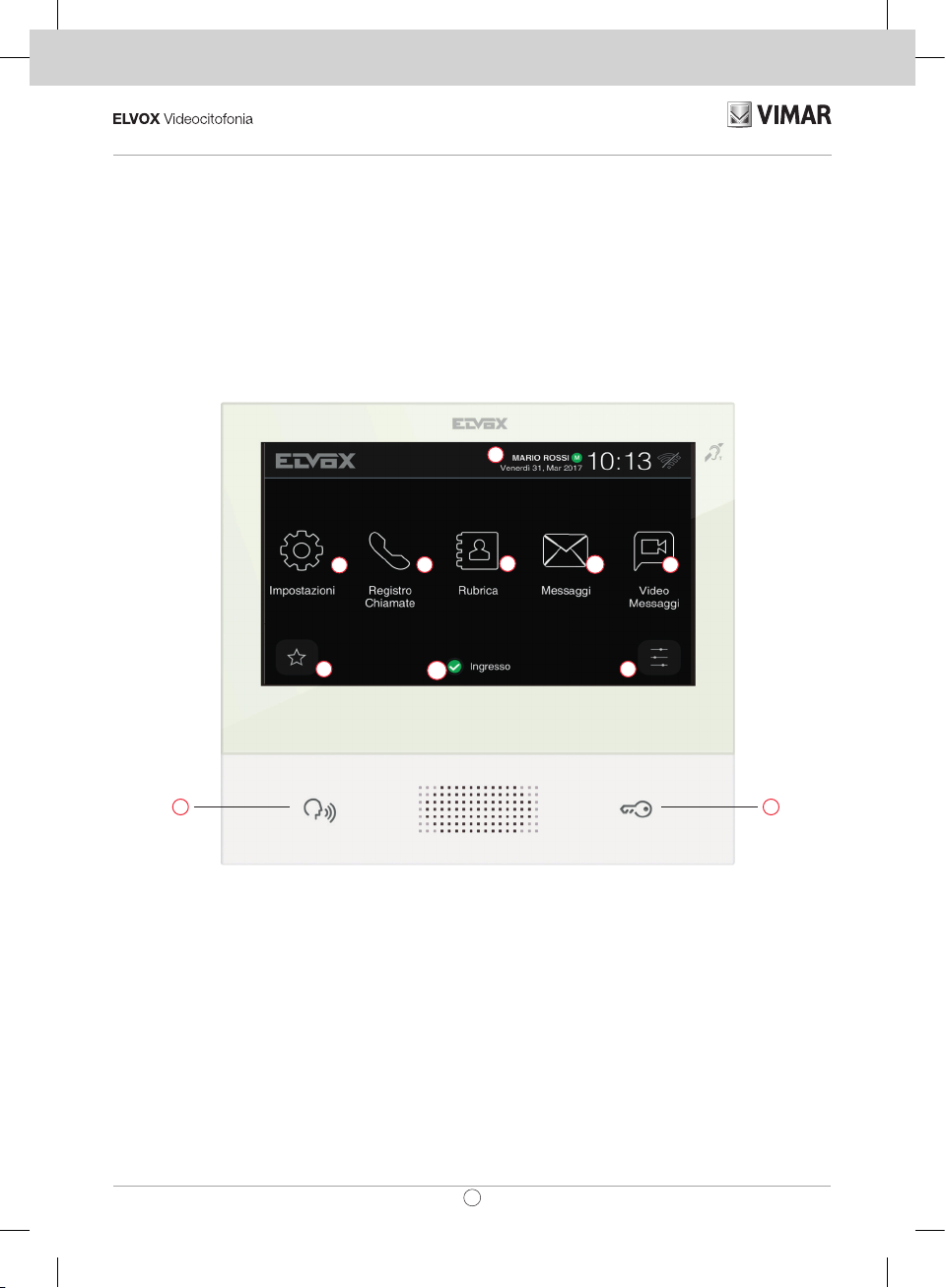
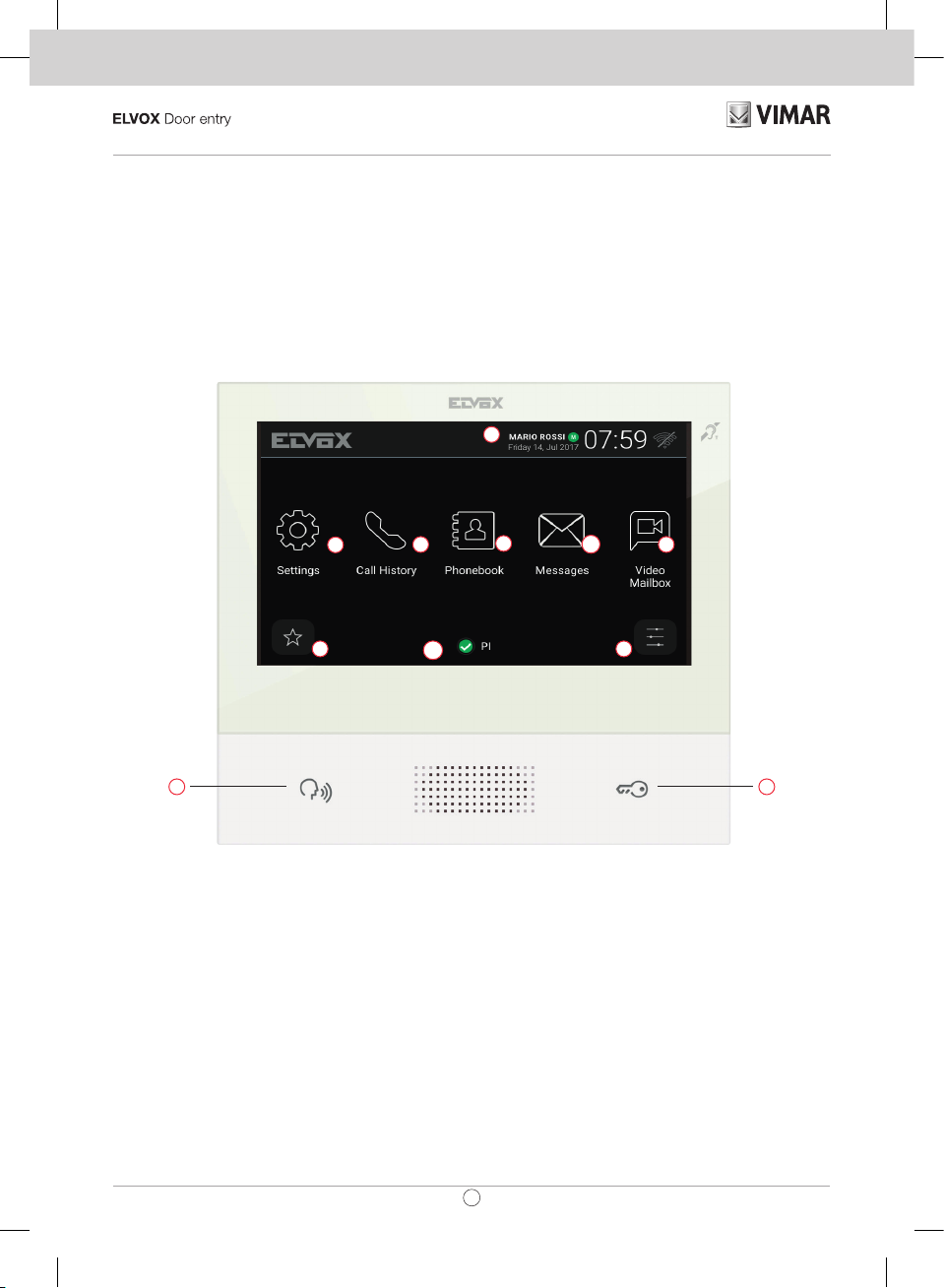
Descrizione interfaccia utente
c
d
i
e
m
f
g
h
l
ba
a) Tasto Parla/Ascolta - Su chiamata entrante, premendo il tasto si accetta la chiamata. In conversazione, si esclude/riattiva il
microfono (funzione mute), alternativamente. Negli altri casi la pressione determina l’esecuzione della funzione con gurata,
ad esempio l’autoaccensione di uno speci co posto esterno.
b) Tasto Serratura - Durante la chiamata o conversazione con posto esterno, premendo il tasto si attiva l’uscita serratura
del posto esterno, se precedentemente con gurata. Negli altri casi la pressione determina l’esecuzione della funzione
con gurata, ad esempio l’attivazione dell’uscita serratura di uno speci co posto esterno.
c) Intestazione – Nome dell’utenza, data e ora, indicazione capogruppo (M), icone di stato.
d) Impostazioni – Parametri con gurabili dall’utente: nome dell’utenza, nome identi cativo del dispositivo, lingua dell’interfac-
cia, data e ora (automatica o manuale), luminosità display e retroilluminazione tasti, suonerie, volumi, opzioni di chiamata
e messaggio di video-segreteria. Alcuni dei parametri sono con gurabili solo sul videocitofono master dell’utenza.
e) Registro chiamate – Elenco delle chiamate, entranti ed uscenti, risposte ri utate e perse.
6
40607_49400925a0_Quik Guide_01.indd 6 27/09/2017 16:39:05
IT
Page 7
TAB: 40607
IT
f) Rubrica – Raccoglie tutti i contatti d’impianto suddivisi in base alla tipologia:
•
Casa: videocitofoni dell’utenza.
•
Preferiti: contatti selezionati dall’utente per accesso veloce da Menu preferiti.
•
Utenti: altre utenze d’impianto.
•
Posti Esterni: posti esterni accessibili nell’impianto.
•
TVCC: telecamere TVCC congurate per essere accessibili dal videocitofono.
•
Portieri: postazioni centralino di portineria contattabili dal videocitofono.
•
Attuazioni: attuazioni installate nell’impianto e a cui l’utente ha accesso; consentono l’implementazione di funzionalità
quali, ad esempio, apertura serrature e accensione luci di servizio.
g) Messaggi – Elenco dei messaggi di testo ricevuti ed invitati.
h) Video Messaggi – Elenco dei messaggi, audio e audio-video, raccolti dal servizio di video-segreteria.
i) Menu preferiti – Accesso ai contatti selezionati dall’utente: a seconda della tipologia di contatto è possibile, ad esempio,
avviare una chiamata o un auto-inserimento, attivare un’attuazione, visualizzare le immagini riprese da una telecamera
TVCC.
l) Menu impostazioni veloci – Accesso alle regolazioni principali: volume suoneria, attivazione/disattivazione suoneria,
luminosità display, attivazione/disattivazione servizio di video-segreteria, attivazione modalità pulizia.
m) Stato – Visualizza e permette di impostare lo stato dell’utenza (ovvero di tutti i videocitofoni che afferiscono alla stesso
utente): Online o Non Disturbare. In stato Non Disturbare tutte le chiamate entranti vengono riutate; in caso sia attivo
il servizio di video-segreteria, viene proposto al chiamante di lasciare un messaggio audio o audio/video. In stato Online
le chiamate entranti vengono noticate tramite suoneria e feedback visivo sul display.
Per maggiori informazioni su schermate, tasti, funzioni di chiamata, impostazioni, e rubrica si consiglia di consultare il Manuale
Utente scaricabile dal sito www.vimar.com
Regole di installazione
L’installazione deve essere effettuata con l’osservanza delle disposizioni regolanti l’installazione del materiale elettrico in vigore
nel Paese dove i prodotti sono installati.
Conformità normativa
Direttiva RED
Norme EN 301 489-17, EN 300 328, EN 62311, EN 60065, EN60118-4.
Vimar S.p.A. dichiara che l’apparecchiatura radio riferimento di tipo 40607 è conforme alla direttiva 2014/53/UE. Il testo completo
della dichiarazione di conformità UE è disponibile al seguente indirizzo Internet: www.vimar.com
RAEE - Informazione agli utilizzatori
Il simbolo del cassonetto barrato riportato sull’apparecchiatura o sulla sua confezione indica che il prodotto alla ne
della propria vita utile deve essere raccolto separatamente dagli altri riuti. L’utente dovrà, pertanto, conferire l’apparecchiatura giunta a ne vita agli idonei centri comunali di raccolta differenziata dei riuti elettrotecnici ed elettronici. In
alternativa alla gestione autonoma è possibile consegnare l’apparecchiatura che si desidera smaltire al rivenditore, al momento
dell’acquisto di una nuova apparecchiatura di tipo equivalente. Presso i rivenditori di prodotti elettronici con supercie di vendita
di almeno 400 m2 è inoltre possibile consegnare gratuitamente, senza obbligo di acquisto, i prodotti elettronici da smaltire con
dimensioni inferiori a 25 cm. L’adeguata raccolta differenziata per l’avvio successivo dell’apparecchiatura dismessa al riciclaggio, al trattamento e allo smaltimento ambientalmente compatibile contribuisce ad evitare possibili effetti negativi sull’ambiente
e sulla salute e favorisce il reimpiego e/o riciclo dei materiali di cui è composta l’apparecchiatura.
7
40607_49400925a0_Quik Guide_01.indd 7 27/09/2017 16:39:05
Page 8

TAB: 40607
EN
The instructions manual can be downloaded from the website www.vimar.com
Description
Wall-mounted hands-free video entryphone for IP system with touchscreen colour LCD display, capacitive keyboard for door
entry system functions and intercom calls, teleloop for hearing aids, bracket for fixing in round or rectangular mounting box.
Technical characteristics
• Display 7 inches, 800x480, 16M colours.
• Touchscreen + 2 backlit capacitive keys.
• Full-duplex hands-free with echo canceller and teleloop function.
• Assembly: wall-mounting, with metal bracket, in box: circular 2M (Vimar V71701), 3M (Vimar V71303, V71703) horizontal
and vertical, 4+4M (Vimar V71318, V71718) and square, British standard.
• Desktop installation is possible with the desktop base accessory 40195.
• Dimensions: 166 x 184 x 24.2 (on wall).
• Supply voltage: PoE, class 0.
• Average PoE consumption: 8 W
• Operating temperature: -5 to 40°C.
Main functions
• Receiving video calls from speech unit.
• Speech unit self-starting.
• Speech unit lock opening.
• Intercom audio calls.
• Call transfer.
• System implementation activation (staircase light, auxiliary functions).
• System contacts list and favourites menu for quick access.
• Configurable video voicemail.
• Receiving and sending text messages.
• Multiple ringtones configurable from the ones available in the device.
• Audio and video call adjustments.
• Input for landing bell.
• Mounting frame for IP CCTV integration.
• Mounting frame for remote call service on smartphone/tablet via Wi-Fi connectivity.
Audio frequency function for hearing aids (teleloop)
The video entryphone can be used by people wearing hearing aids.
For correct functioning of the hearing aid, please refer to its instruction manual. Any metal objects or electronic equipment in
the vicinity may affect the quality of the sound received by the hearing aid.
Maintenance
Clean using a soft cloth. Do not pour water onto the appliance and do not use any type of chemical product.
Warnings for the user
Do not open or tamper with the appliance.
In the event of trouble, call in specialized personnel.
8
40607_49400925a0_Quik Guide_01.indd 8 27/09/2017 16:39:05
Page 9
TAB: 40607
EN
Installation
Important: The device should be installed at a height of approximately 160 cm off the floor, taking care not to expose it to
direct sources of light so as to avoid annoying glare on the surface of the LCD screen.
Note: Fig. 1 shows the recommended installation distances, unless otherwise specified by current regulations.
1. Secure the plate to the wall, with metal bracket, in box: circular 2M (Vimar V71701), 3M (Vimar V71303, V71703) horizontal
and vertical, 4+4M (Vimar V71318, V71718) and square, British standard.
2. Connect the RJ45 PLUG of the video door entry system network and, when present, the landing push button, wire the
FP - M terminal block (Fig. 6).
3. Install the video entryphone as follows: position the video entryphone on the plate keeping it slightly raised. While keeping
the front panel pressed, apply a light downward pressure until it clicks into place.
4. Should you need to remove the monitor you need to apply a light pressure on the lever (Fig. 3) and raise it (from the bottom
upwards) so as to release the monitor from the chassis.
Fig. 1
Fig. 2
> 10 cm
1,20m1,60 / 1,65m
9
40607_49400925a0_Quik Guide_01.indd 9 27/09/2017 16:39:05
Page 10
TAB: 40607
EN
Fig. 3
Interfaces and terminals
• PoE: interface RJ45 Ethernet 10/100 Mbps, PoE class 0.
• FP: NO input for dry contact, landing call push button (reference to terminal M).
• M: Earth reference for landing push button.
Installation guidelines:
• The RJ45 network interface is to be connected solely to a SELV (Safety Extra-Low Voltage) network.
• The PoE (Power-over-Ethernet PSE, Power Sourcing Equipment) power supply unit must provide electrical insulation be
tween any accessible conductor including the earth wire, if there is one, and all the contacts of the network ports, including
those not used by the PSE or by the device to be installed.
-
Fig. 6
10
40607_49400925a0_Quik Guide_01.indd 10 27/09/2017 16:39:06
Page 11
TAB: 40607
EN
Initial switch-on
The suitably wired and powered device shows, when not congured, the following screen on which are shown: IP address (automatic link-local address temporary), MAC address, system ID, rmware version. By default, all the devices have ID 00.00.000
that is a non-specied ID: to simplify system conguration via Video Door IP Manager, the installer can set the ID on each
device. Press Change ID and on the next screen assign the ID: select an unequivocal ID for each user; assign the same ID to
all the video entryphones belonging to the same user.
When installing a KIT, setting the ID is unimportant: follow the instructions in the following section to activate the KIT. On the
other hand, the installer must nish conguring and activating the device via the Video Door IP Manager software (refer to
the VDIPM documentation).
When installing a KIT, setting the ID is unimportant: follow the instructions in the following section to activate the KIT. On the
other hand, the installer must nish conguring and activating the device via the Video Door IP Manager software (refer to
the VDIPM documentation).
11
40607_49400925a0_Quik Guide_01.indd 11 27/09/2017 16:39:07
Page 12
TAB: 40607
EN
KIT installation
Power up the KIT devices, such as the TAB 7S IP (art. 40607) and IP A/V unit (art. 41006), connecting them to the same
network, and wait until the initial screen described above appears on the display. Press the Menu icon in the top left corner
and select the KIT conguration option. Complete the steps (language and date/time settings) and wait for the procedure to
complete, at which point the device will reboot in operating mode.
If an error message is shown on the screen, make sure that all the devices are properly connected and powered up, then
try again.
Description of user interface
c
d
i
e
m
f
g
h
l
ba
a) Talk/listen button - On an incoming call, press this button to accept the call. In conversation, the microphone is switched
on/off (mute function), alternately. In all other cases, pressing the button causes the congured function to be triggered,
for example self-starting a specic speech unit.
b) Lock button - During a call or a conversation with a speech unit, press this button to activate the lock output of the speech
unit, if previously congured. In all other cases, pressing the button causes the congured function to be triggered, for
example activating the lock output of a specic speech unit.
c) Header – User name, date and time, master device (M) indication, status icons.
d) Settings – User congurable parameters: user name, device identication name, interface language, date and time (auto
matic or manual), display brightness and button backlighting, ringtones, volume, call options and video voicemail message.
Some of the parameters can only be congured on the user's master video entryphone.
-
e) Call log – List of incoming and outgoing calls, rejected and missed calls.
f) Contacts list – Collects all the system contacts divided by type:
12
40607_49400925a0_Quik Guide_01.indd 12 27/09/2017 16:39:07
Page 13
TAB: 40607
EN
•
Home: user's video entryphones.
•
Favourites: contacts selected by the user for fast access from the Favourites menu.
•
Users: other system users.
•
Speech Units: accessible speech units in the system.
•
CCTV: CCTV cameras congured to be accessible from the video entryphone.
•
Receptions: reception switchboard stations that can be contacted from the video entryphone.
•
Implementations: implementations installed in the system that the user can access; they permit implementing functions
such as, for instance, opening locks and switching on service lights.
g) Messages – List of sent and received text messages.
h) Video Messages – List of audio and audio-video messages collected by the video voicemail service.
i) Favourites menu – Access to contacts selected by the user: depending on the type of contact you can, for example, initiate
a call or a self-start, activate an actuation or view images captured by a CCTV camera.
l) Quick settings menu – Access to the main settings: ringtone volume, display brightness, video voicemail service on/off.
m) Status – Displays and allows you to set the user status, i.e. all devices, video entryphones and mobile devices that belong
to the same user: Online or Do Not Disturb. This status is applied to all devices and can be set using any device. In Do
Not Disturb status, all incoming calls are rejected; if the video voicemail service is enabled, the caller is asked to leave
an audio or audio/video message. In Online status, incoming calls are indicated by a ringtone and visual feedback on the
display.
For more information on screens, buttons, call functions, settings, and the contacts list, please refer to the User's Manual that
you can download from the website www.vimar.com
Installation rules
Installation should be carried out observing current installation regulations for electrical systems in the Country where the
products are installed.
Conformity
RED directive
Standards EN 301 489-17, EN 300 328, EN 62311, EN 60065, EN60118-4.
Vimar S.p.A. declares that the radio equipment type reference 40607 is in compliance with Directive 2014/53/EU. The full text
of the EU declaration of conformity is available at the following internet address: www.vimar.com
WEEE - Information for users
If the crossed-out bin symbol appears on the equipment or packaging, this means the product must not be included
with other general waste at the end of its working life. The user must take the worn product to a sorted waste center, or
return it to the retailer when purchasing a new one. Products for disposal can be consigned free of charge (without any
new purchase obligation) to retailers with a sales area of at least 400m2, if they measure less than 25cm. An efcient sorted
waste collection for the environmentally friendly disposal of the used device, or its subsequent recycling, helps avoid the potential negative effects on the environment and people’s health, and encourages the re-use and/or recycling of the construction
materials.
13
40607_49400925a0_Quik Guide_01.indd 13 27/09/2017 16:39:07
Page 14
TAB: 40607
FR
Le manuel d'instructions peut être téléchargé sur le site www.vimar.com
Description
Portier-vidéo mains libres en saillie pour système IP avec écran tactile couleurs LCD, clavier capacitif pour fonctions portiers
et appels intercommunicants, téléboucle pour prothèses auditives, étrier de fixation sur boîtier rectangulaire ou rond.
Caractéristiques techniques
• Écran 7 pouces, 800x480, 16M couleurs.
• Écran tactile + 2 touches capacitives rétroéclairées.
• Mains libres full-duplex avec compensation d'écho et fonction téléboucle.
• Montage : en saillie, avec étrier métallique, sur boîtier : rond 2M (Vimar V71701), 3M (Vimar V71303, V71703) horizontal
et vertical, 4+4M (Vimar V71318, V71718) et carré British standard.
• L’installation est possible en version de table grâce à la base de table 40195.
• Dimensions : 166 x 184 x 24,2 (en saillie).
• Alimentation : PoE, classe 0.
• Consommation typique PoE : 8 W
• Température de fonctionnement : -5 ÷ 40 °C.
Fonctions principales
• Réception d'appels vidéo depuis un poste extérieur.
• Auto-allumage poste extérieur.
• Ouverture gâche poste extérieur.
• Appels audio intercommunicants.
• Transfert d'appel.
• Activation fonctions de l’installation (éclairage escalier, fonctions auxiliaires).
• Répertoire de l’installation et menus favoris pour l'accès rapide.
• Mémoire vidéo configurable.
• Réception et envoi de textos.
• Sonneries multiples configurables parmi celles disponibles sur le dispositif.
• Réglages audio et vidéo en appel.
• Entrée pour sonnette de palier.
• Support pour intégration CCTV IP.
• Support pour service d'appel à distance sur smartphone/tablette via connectivité Wi-Fi.
Fonction audiofréquence pour prothèses auditives (téléboucle)
Le portier-vidéo est adapté aux porteurs de prothèses auditives.
Pour assurer le fonctionnement de l'appareil acoustique, se reporter au mode d'emploi de ce dernier. La présence d'objets
métalliques ou d'appareils électroniques peut compromettre la qualité de la réception sur l’appareil acoustique.
Maintenance
Nettoyer avec un chiffon doux. Ne pas verser d'eau sur l'appareil et n'utiliser aucun produit chimique.
Recommandations pour l’utilisateur
Ne pas ouvrir ni modier l’appareil.
En cas de panne, s'adresser à un technicien spécialisé.
14
40607_49400925a0_Quik Guide_01.indd 14 27/09/2017 16:39:07
Page 15

TAB: 40607
FR
Installation
Important : Il est conseillé d'installer le dispositif à 160 cm du sol en ayant soin de ne pas l'exposer directement à une source
d'éclairage afin d'éviter tout reflet sur l'écran LCD.
Remarque : la fig. 1 fournit les dimensions d'installation conseillées, sauf indications contraires de la norme locale en vigueur
en la matière.
1. Fixer la plaque en saillie, avec étrier métallique, sur boîtier : rond 2M (Vimar V71701), 3M (Vimar V71303, V71703) hori
zontal et vertical, 4+4M (Vimar V71318, V71718) et carré British standard.
2. Connecter le PLUG RJ45 du réseau portier-vidéo et, en présence d'un bouton de palier, câbler le bornier FP - M (fig. 6).
3. Positionner le portier-vidéo de la manière suivante : placer le portier-vidéo sur la plaque en le soulevant légèrement. En
appuyant sur la façade, exercer une légère pression vers le bas jusqu'à l'enclenchement.
4. Pour enlever la plaque-vidéo, exercer une légère pression sur le levier spécial (Fig. 3) et le soulever de bas en haut pour
décrocher le portier-vidéo du châssis.
-
Fig. 1
Fig. 2
> 10 cm
1,20m1,60 / 1,65m
15
40607_49400925a0_Quik Guide_01.indd 15 27/09/2017 16:39:08
Page 16

TAB: 40607
FR
Fig. 3
Interfaces et bornes
• PoE : interface RJ45 Ethernet 10/100 Mbps, PoE classe 0.
• FP : Entrée NO pour contact sec, bouton palier (référence à la borne M).
• M : Référence de masse pour bouton palier.
Consignes d'installation :
• Connecter exclusivement l'interface de réseau RJ45 à un réseau SELV (Safety Extra-Low Voltage).
• L'alimentation PoE (Power-over-Ethernet PSE, Power Sourcing Equipment) doit assurer une isolation électrique entre toute
sorte de conducteur accessible, y compris le conducteur de terre, s'il est présent, et tous les contacts des ports de réseau,
y compris ceux utilisés par le PSE ou le dispositif à installer.
Fig. 6
16
40607_49400925a0_Quik Guide_01.indd 16 27/09/2017 16:39:08
Page 17

TAB: 40607
FR
Premier allumage
Le dispositif, convenablement câblé et alimenté, présente, lorsqu'il n'est pas conguré, la page suivante qui indique : adresse
IP (automatic link-local address momentané), adresse MAC, identiant d'installation, version microprogramme. Par défaut, tous
les dispositifs ont l'ID 00.00.000, à savoir un identiant non précisé : pour simplier l’activité de conguration de l’installation via
Video Door IP Manager, l’installateur peut dénir l’ID sur chaque dispositif. Appuyer sur Change ID et attribuer l'identiant sur
la page suivante : sélectionner un ID univoque pour chaque usager ; attribuer le même ID à tous les portiers-vidéo appartenant
au même usager.
L'ID n'a pas d'importance pour l'installation du KIT : suivre les instructions du chapitre ci-dessous pour activer le KIT. Par
contre, l'installateur doit congurer et activer le dispositif avec le logiciel Video Door IP Manager (se référer à la documentation
relative à VDIPM).
17
40607_49400925a0_Quik Guide_01.indd 17 27/09/2017 16:39:09
Page 18

TAB: 40607
FR
Installation du KIT
Alimenter les dispositifs du KIT, par exemple TAB 7S IP (art. 40607) et l' unité IP A/V (art. 41006), en se connectant au ré-
seau et attendre que la page d'accueil décrite plus haut s'afche sur l'écran. Appuyer sur l'icône Menu en haut et à gauche
et sélectionner l'option de conguration du KIT. Suivre les étapes (dénir la langue, la date et l'heure) et attendre la n de la
procédure : quand elle est terminée le dispositif se rallume, prêt à fonctionner.
Si une erreur s'afche sur l'écran, vérier que tous les dispositifs sont correctement reliés et alimentés et réessayer.
Description interface utilisateur
c
d
i
e
m
f
g
h
l
ba
a) Touche Parler/Écouter - Sur appel entrant, en appuyant sur la touche, l'appel est accepté. En conversation, on exclut/
remet en service le micro (fonction mute), successivement. Dans les autres cas, l'appui permet d’exécuter la fonction
congurée, par exemple l’auto-allumage d'un poste extérieur précis.
b) Touche Gâche - Durant l'appel ou la conversation avec un poste extérieur, il suft d'appuyer sur la touche pour activer la
sortie gâche du poste extérieur, à condition qu'elle ait été préalablement congurée. Dans les autres cas, l'appui permet
d’exécuter la fonction congurée, par exemple l’activation de la sortie gâche d'un poste extérieur précis.
c) En-tête – Nom de l’utilisateur, date et heure, indication du chef de groupe (M), icônes d’état.
d) Réglages – Paramètres congurables par l’usager : nom de l’usager, identiant du dispositif, langue de l’interface, date
et heure (automatique ou manuel), luminosité écran et rétroéclairage des touches, sonneries, volumes, options d'appel
et message de mémoire vidéo. Certains paramètres peuvent être congurés uniquement sur le portier-vidéo master de
l’usager.
18
40607_49400925a0_Quik Guide_01.indd 18 27/09/2017 16:39:10
Page 19

TAB: 40607
FR
e) Registre appels – Liste des appels entrants et sortants, réponses refusées et appels perdus.
f) Répertoire – Regroupe tous les contacts du système, divisés par type :
•
Maison : portiers-vidéo de l’usager.
•
Favoris : contacts sélectionnés par l’usager pour l'accès rapide à partir du Menu favoris.
•
Usagers : autres usagers du système.
•
Postes extérieurs : postes extérieurs accessibles au sein du système.
•
CCTV : caméras CCTV congurées pour être accessibles à partir du portier-vidéo.
•
Portiers : postes de standard de conciergerie pouvant être contactés à partir d'un portier-vidéo.
•
Activations : fonctions du système auxquelles l'usager peut accéder ; elles permettent d'élargir les fonctionnalités avec,
par exemple, l'ouverture gâche et l'allumage de l'éclairage de service.
g) Messages – Liste des textos reçus et envoyés.
h) Messages vidéo – Liste des messages, audio et audio-vidéo, enregistrés par le service de mémoire vidéo.
i) Menu Favoris – Accès aux contacts sélectionnés par l’utilisateur : selon le type de contact, il est possible, par exemple,
de lancer un appel ou une auto-activation, d’activer une fonction, de visualiser les images lmées par une caméra CCTV.
l) Menu réglages rapides – Accès aux contacts sélectionnés par l’utilisateur : selon le type de contact, il est possible, par
exemple, de lancer un appel ou une auto-activation, d'activer une fonction, de visualiser les images lmées par une caméra
CCTV.
m) État – Afchage et dénition de l’état du service c’est-à-dire de tous les portiers-vidéo et dispositifs mobiles se rapportant
au même utilisateur : En ligne ou Ne pas déranger. L’état est univoque et peut être conguré sur n’importe quel dispositif.
En mode Ne pas déranger, tous les appels entrants sont refusés ; si le répondeur vidéo est actif, l’appelant peut laisser un
message audio ou audio/vidéo. En ligne, les appels entrants sont notiés par une sonnerie et un retour visuel sur l’écran.
Pour des informations plus complètes sur les pages afchées, les touches, les fonctions d'appel, les réglages et le répertoire,
il est conseillé de consulter le Manuel Utilisateur en le téléchargeant sur le site www.vimar.com
Règles d’installation
L’installation doit être effectuée dans le respect des dispositions régulant l’installation du matériel électrique en vigueur dans
le Pays d’installation des produits.
Conformité aux normes
Directive RED
Normes EN 301 489-17, EN 300 328, EN 62311, EN 60065, EN60118-4.
Vimar S.p.A. déclare que l'équipement radio référence 40607 est conforme à la directive 2014/53/UE. Le texte complet de la
déclaration de conformité UE est disponible à l'adresse Internet suivante. www.vimar.com
DEEE - Informations pour les utilisateurs
Le symbole du caisson barre, la ou il est reporte sur l’appareil ou l’emballage, indique que le produit en n de vie doit
etre collecte separement des autres dechets. Au terme de la duree de vie du produit, l’utilisateur devra se charger de
le remettre a un centre de collecte separee ou bien au revendeur lors de l’achat d’un nouveau produit. Il est possible
de remettre gratuitement, sans obligation d’achat, les produits a eliminer de dimensions inferieures a 25 cm aux revendeurs
dont la surface de vente est d’au moins 400 m2. La collecte separee appropriee pour l’envoi successif de l’appareil en n de
vie au recyclage, au traitement et a l’elimination dans le respect de l’environnement contribue a eviter les effets negatifs sur
l’environnement et sur la sante et favorise le reemploi et/ou le recyclage des materiaux dont l’appareil est compose.
19
40607_49400925a0_Quik Guide_01.indd 19 27/09/2017 16:39:10
Page 20

TAB: 40607
ES
El manual de instrucciones se puede descargar desde la página www.vimar.com
Descripción
Videoportero manos libres de superficie para sistema IP con pantalla en color LCD touch-screen, teclado capacitivo para
funciones de portero automático y llamadas intercomunicantes, transmisor inductivo, soporte para fijación en caja rectangular o redonda.
Características técnicas
• Pantalla 7", 800x480, 16M de colores.
• Touchscreen + 2 teclas capacitivas retroiluminadas.
• Manos libres full-duplex con supresor de eco y función transmisor inductivo.
• Montaje: de superficie, con soporte metálico, sobre caja: circular 2M (Vimar V71701), 3M (Vimar V71303, V71703) hori
zontal y vertical, 4+4M (Vimar V71318, V71718) y cuadrada British standard.
• El montaje en versión de sobremesa es posible gracias al correspondiente accesorio 40195.
• Tamaño: 166 x 184 x 24,2 (de superficie).
• Alimentación: PoE, clase 0.
• Consumo típico PoE: 8 W
• Temperatura de funcionamiento: -5 ÷ 40 °C.
Funciones principales
• Recepción de videollamadas desde el aparato externo.
• Autoencendido del aparato externo.
• Apertura de cerradura del aparato externo.
• Llamadas intercomunicantes.
• Desvío de llamada.
• Activación de funciones (luz de escalera, funciones auxiliares).
• Agenda y menús favoritos para acceso rápido.
• Videocontestador automático configurable.
• Recepción y envío de mensajes de texto.
• Tonos múltiples, configurables entre los disponibles en el dispositivo.
• Ajustes de audio y vídeo en llamada.
• Entrada para timbre fuera de la puerta.
• Soporte para integración CCTV IP.
• Soporte para servicio de llamada remota por smartphone/tablet mediante conectividad Wi-Fi.
-
Función de audiofrecuencia para audífonos (transmisor inductivo)
El videoportero puede ser utilizado por personas con audífono.
Para el correcto funcionamiento del audífono, consulte el correspondiente manual de instrucciones. La presencia de objetos
metálicos o aparatos electrónicos puede perjudicar la calidad del sonido percibido con el audífono.
Mantenimiento
Limpie con un paño suave. No moje el aparato con agua y no utilice ningún tipo de producto químico.
Advertencias para el usuario
No abra, ni manipule el aparato.
En caso de avería, acuda a personal especializado.
20
40607_49400925a0_Quik Guide_01.indd 20 27/09/2017 16:39:10
Page 21

TAB: 40607
ES
Montaje
Importante: Se recomienda instalar el dispositivo a una altura de unos 160 cm del suelo teniendo cuidado de no exponerlo a
fuentes directas de iluminación para evitar molestos fenómenos de reflexión en la superficie de la pantalla LCD.
Nota: en la Fig. 1 se muestran las medidas de instalación recomendadas, salvo otras indicaciones de la norma local vigente.
1. Fije la placa a la pared, con soporte metálico, sobre la caja: circular 2M (Vimar V71701), 3M (Vimar V71303, V71703)
horizontal y vertical, 4+4M (Vimar V71318, V71718) y cuadrada British standard.
2. Conecte el PLUG RJ45 de la red del videoportero y, si está el pulsador fuera de la puerta, cablee la caja de bornes FP - M
(fig. 6).
3. Montaje del videoportero: colóquelo sobre la placa manteniéndolo ligeramente levantado y entonces, manteniendo presio
nado el frente, empuje suavemente hacia abajo hasta que quede encajado.
4. Si fuera necesario soltar el videoportero, hay que ejercer una ligera presión en la pestaña correspondiente (fig. 3) y levantar
(de abajo hacia arriba) para desenganchar el videoportero del bastidor.
-
Fig. 1
Fig. 2
> 10 cm
1,20m1,60 / 1,65m
21
40607_49400925a0_Quik Guide_01.indd 21 27/09/2017 16:39:10
Page 22

TAB: 40607
ES
Fig. 3
Interfaces y bornes
• PoE: interfaz RJ45 Ethernet 10/100 Mbps, PoE clase 0.
• FP: Entrada NO para contacto libre de tensión, pulsador de llamada desde fuera de la puerta (referencia al borne M).
• M: Referencia de masa para el pulsador fuera de la puerta.
Indicaciones de montaje:
• La interfaz de red RJ45 debe conectarse exclusivamente a una red SELV (Safety Extra-Low Voltage).
• El alimentador PoE (Power-over-Ethernet PSE, Power Sourcing Equipment) debe suministrar aislamiento eléctrico entre
cualquier conductor accesible, incluido el conductor de tierra si lo hay, y todos los contactos de las puertas de red, incluidos
los inutilizados por el PSE o el dispositivo a instalar.
Fig. 6
22
40607_49400925a0_Quik Guide_01.indd 22 27/09/2017 16:39:11
Page 23

TAB: 40607
ES
Primer encendido
El dispositivo, adecuadamente cableado y alimentado, sin estar congurado, presenta la siguiente pantalla donde aparecen:
dirección IP (automatic link-local address temporal), dirección MAC, identicación de la instalación, versión de rmware. Todos
los dispositivos tienen predeterminado el ID 00.00.000, es decir una identicación no especicada: para simplicar la actividad
de conguración de la instalación con Video Door IP Manager, el instalador puede congurar el ID en cada dispositivo. Pulse
Change ID y en la pantalla siguiente asigne la identicación: seleccione un ID unívoco para cada usuario; asigne el mismo ID
a todos los videoporteros perteneciente al mismo usuario.
En caso de montaje de un KIT, la conguración del ID es irrelevante: para la activación del KIT, siga las instrucciones del
capítulo siguiente. En los demás casos, el instalador debe completar la conguración y la activación del dispositivo mediante
el software Video Door IP Manager (consulte la documentación correspondiente a VDIPM).
23
40607_49400925a0_Quik Guide_01.indd 23 27/09/2017 16:39:12
Page 24

TAB: 40607
ES
Montaje del KIT
Alimente los dispositivos del KIT, por ejemplo TAB 7S IP (art. 40607) y la unidad IP A/V (art. 41006) conectándolos a la
misma red y espere que aparezca la pantalla inicial descrita anteriormente. Pulse el icono Menú en la esquina superior
izquierda y seleccione la opción de conguración del KIT. Siga los pasos indicados (conguración de idioma y fecha/hora) y
espere que termine el procedimiento: al nal el dispositivo se reinicia en el modo de funcionamiento.
Si se notica un error en pantalla, compruebe que todos los dispositivos estén conectados y alimentados correctamente e
inténtelo de nuevo.
Descripción interfaz de usuario
c
d
i
e
m
f
g
h
l
ba
a) Tecla Hablar/Escuchar - Al producirse una llamada entrante, pulsando la tecla se acepta la llamada. Durante la con-
versación, se desactiva/reactiva alternativamente el micrófono (función mute). En los demás casos, al pulsar la tecla se
ejecuta la función congurada, por ejemplo el autoencendido de un determinado aparato externo.
b) Tecla Cerradura - Durante la llamada o conversación con aparato externo, al pulsar la tecla se activa la salida de la
cerradura del aparato externo, si estaba previamente congurada. En los demás casos, al pulsar la tecla se ejecuta la
función congurada, por ejemplo la activación de la salida de la cerradura de un determinado aparato externo.
c) Encabezado – Nombre de usuario, fecha y hora, indicación de dispositivo principal (M), iconos de estado.
d) Ajustes – Parámetros congurables por el usuario: nombre del usuario, identicación del dispositivo, idioma de la interfaz,
fecha y hora (automática o manual), brillo de pantalla y retroiluminación de teclas, tonos, volúmenes, opciones de llamada y
24
40607_49400925a0_Quik Guide_01.indd 24 27/09/2017 16:39:12
Page 25

TAB: 40607
ES
mensaje de videocontestador. Algunos de los parámetros pueden congurarse solo en el videoportero master del usuario.
y) Registro de llamadas – Listado de llamadas, entrantes y salientes, respuestas rechazadas y perdidas.
f) Agenda – Recoge todos los contactos de la instalación repartidos por tipo:
•
Casa: videoporteros del usuario.
•
Favoritos: contactos seleccionados por el usuario para su acceso rápido desde el Menú favoritos.
•
Usuarios: otros usuarios de la instalación.
•
Aparatos externos: aparatos externos accesibles en la instalación.
•
CCTV: cámaras CCTV conguradas para que sean accesibles desde el videoportero.
•
Conserjerías: puestos de centralita de conserjería que se pueden contactar desde el videoportero.
•
Funciones: ya están en la instalación y el usuario puede acceder a las mismas; permiten la implementación de funciones
como por ejemplo, apertura de cerraduras y encendido de luces de servicio.
g) Mensajes – Listado de los mensajes de texto recibidos y enviados.
h) Videomensajes – Listado de los mensajes, de audio y audio-vídeo, recogidos por el servicio de videocontestador.
i) Menú Favoritos – Acceso a los contactos seleccionados por el usuario: según el tipo de contacto, por ejemplo, es posible
iniciar una llamada o un autoencendido, activar una función, ver las imágenes captadas por una cámara TVCC.
l) Menú ajustes rápidos – Acceso a los ajustes principales: volumen del timbre, brillo de pantalla, activación/desactivación
del servicio de videocontestador.
m) Estado – Muestra y permite congurar el estado del usuario, es decir de todos los dispositivos, videoporteros y móviles
del mismo usuario: Online o Do Not Disturb. El estado es unívoco y puede congurarse desde cualquier dispositivo. En
Do Not Disturb se rechazan todas las llamadas entrantes; si está activado el servicio de videocontestador, se invita a
quien llama a dejar un mensaje de audio o audio/vídeo. En estado Online las llamadas entrantes se notican con un tono
y feedback visual en la pantalla.
Para más información acerca de pantallas, teclas, funciones de llamada, ajustes y agenda, consulte el Manual de usuario que
se puede descargar de www.vimar.com
Normas de instalación
El aparato se ha de instalar en conformidad con las disposiciones sobre material eléctrico vigentes en el País.
Conformidad normativa
Directiva RED
Normas EN 301 489-17, EN 300 328, EN 62311, EN 60065, EN60118-4.
Vimar S.p.A. declara que el equipo radio de referencia de tipo 40607 es conforme a la directiva 2014/53/UE. El texto completo
de la declaración de conformidad UE está disponible en la siguiente página web: www.vimar.com
RAEE - Información para los usuarios
El simbolo del contenedor tachado, cuando se indica en el aparato o en el envase, indica que el producto, al nal de
su vida util, se debe recoger separado de los demas residuos. Al nal del uso, el usuario debera encargarse de llevar
el producto a un centro de recogida diferenciada adecuado o devolverselo al vendedor con ocasion de la compra de
un nuevo producto. En las tiendas con una supercie de venta de al menos 400 m2, es posible entregar gratuitamente, sin
obligacion de compra, los productos que se deben eliminar con unas dimensiones inferiores a 25 cm. La recogida diferenciada
adecuada para proceder posteriormente al reciclaje, al tratamiento y a la eliminacion del aparato de manera compatible con el
medio ambiente contribuye a evitar posibles efectos negativos en el medio ambiente y en la salud y favorece la reutilizacion
y/o el reciclaje de los materiales de los que se compone el aparato.
25
40607_49400925a0_Quik Guide_01.indd 25 27/09/2017 16:39:12
Page 26

TAB: 40607
DE
Die Anleitung kann von der Website www.vimar.com heruntergeladen werden
Beschreibung
Freisprech-AP-Videohaustelefon für System IP mit LCD-Farbtouchscreen, kapazitiver Tastatur für Haustelefon-Funktionen
und Internrufe, Teleschlinge für Hörgeräte, Haltebügel für rechteckiges oder rundes Gehäuse.
Technische Merkmale
• 7-Zoll-Display, 800x480, 16 M Farben.
• Touchscreen + 2 kapazitive hinterleuchtete Tasten.
• Freisprechfunktion Vollduplex mit Echounterdrückung und Funktion Teleschlinge.
• Aufputzmontage mit Metallbügel, auf Gehäuse: rund 2M (Vimar V71701), 3M (Vimar V71303, V71703) horizontal und
vertikal, 4+4M (Vimar V71318, V71718) und quadratisch British Standard.
• Installation als Tischgerät mithilfe des Tischzubehörs 40195.
• Abmessungen: 166 x 184 x 24.2 (Aufputz).
• Versorgung: PoE, Klasse 0.
• Typischer Verbrauch PoE: 8 W
• Betriebstemperatur: -5 ÷ 40 °C.
Hauptfunktionen
• Empfang von Videorufen von der Außenstelle.
• Selbsteinschaltung Außenstelle.
• Türöffnung Außenstelle.
• Interne Audiorufe.
• Anrufweiterleitung.
• Aktivierung der Betätigung von Anlagenfunktionen (Treppenhauslicht, Zusatzfunktionen).
• Anlagenverzeichnis und Favoritenmenü für den Schnellzugriff.
• Konfigurierbarer Video-Anrufbeantworter.
• Empfangen und Senden von Textnachrichten.
• Unter den im Gerät vorhandenen auswählbare Mehrfachklingeltöne.
• Audio- und Videoeinstellungen während des Anrufs.
• Eingang für Etagenklingel.
• Rahmen für die Integration von IP-Videoüberwachung.
• Rahmen für Fernruf auf Smartphone/Tablet über WLAN-Verbindung.
Tonfrequenz-Funktion für Hörgeräte (Teleschlinge)
Das Videohaustelefon eignet sich für Hörgeräteträger.
Für den korrekten Betrieb des Hörgeräts wird auf die entsprechende Bedienungsanleitung verwiesen. Eventuell vorhandene
Gegenstände aus Metall oder elektronische Geräte können die am Hörgerät empfangene Tonqualität beeinträchtigen.
Wartung
Für die Wartung ein weiches Tuch verwenden. Kein Wasser auf das Gerät verschütten und chemische Reinigungsmittel
vermeiden.
Hinweise für den Benutzer
Das Gerät auf keinen Fall öffnen oder manipulieren.
Bei Störungen Fachpersonal hinzuziehen.
26
40607_49400925a0_Quik Guide_01.indd 26 27/09/2017 16:39:12
Page 27

TAB: 40607
DE
Installation
Wichtig: Das Gerät sollte in einer Höhe von ca. 160 cm zum Boden installiert und keiner direkten Beleuchtung ausgesetzt
werden, um störende Spiegelungen auf dem LCD-Bildschirm zu vermeiden.
Hinweis: Abb. 1 enthält die empfohlenen Einbaumaße, außer bei anderslautenden Vorgaben der einschlägigen lokalen
Rechtsvorschriften.
1. Die Aufputzplatte mit Metallbügel auf Gehäuse montieren: rund 2M (Vimar V71701), 3M (Vimar V71303, V71703) horizontal
und vertikal, 4+4M (Vimar V71318, V71718) und quadratisch British Standard.
2. Das PLUG RJ45 der Videosprechanlage anschließen und, falls die Etagenruftaste vorhanden ist, den Klemmblock FP - M
verdrahten (Abb. 6).
3. Das Videohaustelefon folgendermaßen einsetzen: Das Videohaustelefon in die Platte einsetzen und dabei etwas anheben.
Die Vorderseite festhalten und bis zum hörbaren Einrasten leicht nach unten drücken.
4. Zur Abnahme des Videohaustelefons den Hebel leicht eindrücken (Abb. 3) und (von unten nach oben) anheben, bis sich
das Videohaustelefon aus dem Rahmen löst.
Abb. 1
Abb. 2
> 10 cm
1,20m1,60 / 1,65m
27
40607_49400925a0_Quik Guide_01.indd 27 27/09/2017 16:39:13
Page 28

TAB: 40607
DE
Abb. 3
Schnittstellen und Klemmen
• PoE: Schnittstelle RJ45 Ethernet 10/100 Mbps, PoE Klasse 0.
• FP: Eingang NO für potentialfreien Kontakt, Etagenruftaste (Bezug auf Klemme M).
• M: Massereferenz für Etagenruftaste.
Installationshinweise:
• Die Netzschnittstelle RJ45 ist ausschließlich an ein Netz SELV (Safety Extra-Low Voltage) anzuschließen.
• Das Netzteil PoE (Power-over-Ethernet PSE, Power Sourcing Equipment) muss die elektrische Isolierung zwischen jedem
zugänglichen Leiter einschließlich Erdleiter, sofern vorhanden, und allen Kontakten der Netzanschlüsse einschließlich der
unbenutzten vom PSE oder von dem zu installierenden Gerät bereitstellen.
Abb. 6
28
40607_49400925a0_Quik Guide_01.indd 28 27/09/2017 16:39:13
Page 29

TAB: 40607
DE
Erstmalige Einschaltung
Solange es nicht konguriert ist, erscheint am verdrahteten und mit Strom versorgtem Gerät die unten abgebildete Bildschirmanzeige mit den folgenden Angaben: IP-Adresse (temporäre automatic link-local address), MAC-Adresse, Kennnummer der
Anlage, Firmware-Version. Standardmäßig haben alle Geräte ID 00.00.000 oder nicht angegebene Kennnummer: Zur Ver
einfachung der Anlagenkonguration mittels Video Door IP Manager kann der Installateur die ID an jedem Gerät einstellen.
Die Schaltäche Change ID antippen und auf dem nächsten Bildschirm die Kennnummer zuweisen: Für jeden Benutzer eine
eindeutige ID wählen; allen Videohaustelefonen desselben Benutzers die gleiche ID zuweisen.
Bei Installation eines SETS ist die Einstellung der ID wirkungslos. Die Anweisungen im nächsten Kapitel für die Aktivierung
des SETS befolgen. Der Installateur muss dagegen die Konguration und Aktivierung des Geräts mithilfe der Software Video
Door IP Manager fertigstellen (siehe Dokumentation zu VDIPM).
-
29
40607_49400925a0_Quik Guide_01.indd 29 27/09/2017 16:39:14
Page 30

TAB: 40607
DE
SET-Installation
Die Geräte des SETS, zum Beispiel TAB 7S IP (Art. 40607) und IP-A-/V-Einheit (Art. 41006) über das gleiche Netz versorgen und warten, bis am Display die vorab beschriebene Startseite erscheint. Das Symbol Menü in der oberen Ecke links
antippen und die Kongurationsoption SET auswählen. Die einzelnen Schritte (Einstellung von Sprache und Datum/Uhrzeit)
fertigstellen und auf den Abschluss des Vorgangs warten: Das Gerät startet daraufhin im Betriebsmodus neu.
Sollte ein Fehler am Bildschirm gemeldet werden, muss vor einem erneuten Versuch überprüft werden, ob alle Geräte
korrekt angeschlossen und versorgt sind.
Beschreibung der Benutzerschnittstelle
c
d
i
e
m
f
g
h
l
ba
a) Taste Sprechen/Hören - Durch Drücken dieser Taste wird ein eingehender Ruf angenommen. Wird sie während eines
Gesprächs gedrückt, wird das Mikrofon abwechselnd aus- und wieder eingeschaltet (Funktion mute). In den anderen Fällen
bewirkt der Tastendruck die Ausführung der kongurierten Funktion, zum Beispiel Selbsteinschaltung einer bestimmten
Außenstelle.
b) Taste „Türschloss“ - Während des Rufs oder Gesprächs mit der Außenstelle wird durch Drücken dieser Taste der Türöffner-
Ausgang der Außenstelle aktiviert, sofern zuvor konguriert. In den anderen Fällen bewirkt der Tastendruck die Ausführung
der kongurierten Funktion, zum Beispiel die Aktivierung des Türöffner-Ausgangs einer bestimmten Außenstelle.
c) Header – Name des Benutzers, Datum und Uhrzeit, Angabe des Hauptgeräts (M), Statussymbole.
d) Einstellungen – Benutzerdenierbare Parameter: Benutzername, Kennung des Geräts, Sprache der Schnittstelle, Datum
und Uhrzeit (automatisch oder manuell), Helligkeit Display und Hintergrundbeleuchtung der Tasten, Klingeltöne, Lautstärken,
Rufoptionen und Nachrichten des Video-Anrufbeantworters. Einige der Parameter sind nur am Master-Videohaustelefon
des Benutzers kongurierbar.
30
40607_49400925a0_Quik Guide_01.indd 30 27/09/2017 16:39:15
Page 31

TAB: 40607
DE
e) Rufprotokoll – Verzeichnis der ein- und ausgehenden, unbeantworteten und verpassten Rufe.
f) Namensverzeichnis – Enthält alle Kontakte in der Anlage, aufgeteilt nach Kontakttyp:
•
Eigene: Videohaustelefone des Benutzers.
•
Favoriten: Ausgewählte Kontakte des Benutzers für den Schnellzugriff vom Favoritenmenü.
•
Benutzer: Sonstige Anlagenbenutzer.
•
Außenstellen : Zugängliche Außenstellen in der Anlage.
•
Videoüberwachung: Für den Zugang vom Videohaustelefon kongurierte Überwachungskameras.
•
Pförtnerzentralen: Pförtnerzentralen, die vom Videohaustelefon kontaktiert werden können.
•
Betätigungen: Betätigung von in der Anlage installierten Funktionen, auf die der Benutzer Zugriff hat; ermöglicht die
Implementierung von Funktionen wie zum Beispiel Öffnen von Türschlössern und Einschalten von Lichtern.
g) Nachrichten – Verzeichnis der empfangenen und gesendeten Nachrichten.
h) Video-Nachrichten – Verzeichnis der vom Video-Anrufbeantworter gesammelten Audio- und Audio/Video-Nachrichten.
i) Favoritenmenü – Zugang zu den vom Benutzer ausgewählten Kontakten: Je nach Kontaktart ist es zum Beispiel möglich,
einen Ruf oder eine Selbsteinschaltung zu starten, eine Betätigung zu aktivieren, die von einer Überwachungskamera
aufgezeichneten Bilder anzusehen.
l) Menü Schnelleinstellungen – Zugang zu den Haupteinstellungen: Klingelton-Lautstärke, Display-Helligkeit, Aktivierung/
Deaktivierung Video-Anrufbeantworter.
m) Status – Anzeige und Einstellung des Benutzerstatus, d.h. des Status aller Videohaustelefone und mobilen Geräte, die
zum selben Benutzer gehören: Online oder Bitte nicht stören. Der Status ist eindeutig und kann von einem beliebigen
Gerät aus eingestellt werden. Im Status Bitte nicht stören werden alle eingehenden Rufe abgelehnt; falls der Video-
Anrufbeantworter aktiv ist, wird dem Anrufer vorgeschlagen, eine Audio- oder Audio/Videonachricht zu hinterlassen. Im
Status Online werden die eingehenden Rufe mit Klingelton und visuellem Feedback am Display gemeldet.
Für weitere Informationen über Bildschirmanzeigen, Tasten, Ruffunktionen, Einstellungen und Teilnehmerverzeichnis bitte im
Benutzerhandbuch nachschlagen, das auf der Website www.vimar.com zum Download bereitsteht.
Installationsvorschriften
Die Installation hat gemäß den im jeweiligen Verwendungsland der Produkte geltenden Vorschriften zur Installation elektrischer
Ausrüstungen zu erfolgen.
Normkonformität
RED-Richtlinie
Normen EN 301 489-17, EN 300 328, EN 62311, EN 60065, EN60118-4.
Vimar S.p.A. erklärt, dass die Funkanlage Typ 40607 der Richtlinie 2014/53/EU entspricht. Die vollständige Fassung der EUKonformitätserklärung steht unter folgender Internetadresse zur Verfügung: www.vimar.com
Elektro- und Elektronik-Altgeräte - Informationen für die Nutzer
Das Symbol der durchgestrichenen Mulltonne auf dem Gerat oder seiner Verpackung weist darauf hin, dass das Pro-
dukt am Ende seiner Nutzungsdauer getrennt von den anderen Abfallen zu entsorgen ist. Nach Ende der Nutzungsdau-
er obliegt es dem Nutzer, das Produkt in einer geeigneten Sammelstelle fur getrennte Mullentsorgung zu deponieren
oder es dem Handler bei Ankauf eines neuen Produkts zu ubergeben. Bei Handlern mit einer Verkaufsache von mindestens
2
konnen zu entsorgende Produkte mit Abmessungen unter 25 cm kostenlos und ohne Kaufzwang abgegeben werden.
400 m
Die angemessene Mulltrennung fur das dem Recycling, der Behandlung und der umweltvertraglichen Entsorgung zugefuhrten
Gerates tragt dazu bei, mogliche negative Auswirkungen auf die Umwelt und die Gesundheit zu vermeiden und begunstigt den
Wiedereinsatz und/oder das Recyceln der Materialien, aus denen das Gerat besteht.
31
40607_49400925a0_Quik Guide_01.indd 31 27/09/2017 16:39:15
Page 32

TAB: 40607
PT
É possível descarregar o manual de instruções a partir do site www.vimar.com
Descrição
Videoporteiro alta-voz de parede para sistema IP com visor a cores LCD touch-screen, teclado capacitivo para funções
áudio e chamadas intercomunicantes, teleloop para próteses auditivas, suporte de fixação em caixa retangular ou redonda.
Características técnicas
• Visor de 7 polegadas, 800x480, 16M cores.
• Touchscreen + 2 teclas capacitivas retroiluminadas.
• Alta-voz full-duplex com echo canceller e função teleloop.
• Montagem: na parede, com suporte metálico, em caixa: circular 2M (Vimar V71701), 3M (Vimar V71303, V71703) hori
zontal e vertical, 4+4M (Vimar V71318, V71718) e quadrada British standard.
• É possível a instalação na versão de mesa através do acessório base de mesa 40195.
• Dimensões: 166 x 184 x 24,2 (na parede).
• Alimentação: PoE, classe 0.
• Consumo típico PoE: 8 W
• Temperatura de funcionamento: -5 ÷ 40°C.
Funções principais
• Receção de videochamadas do posto externo.
• Autoacendimento do posto externo.
• Abertura do trinco do posto externo.
• Chamadas áudio intercomunicantes.
• Transferência de chamada.
• Ativação de atuações de sistema (luz das escadas, funções auxiliares).
• Lista de contactos do sistema e menu de favoritos para um acesso rápido.
• Vídeo-atendedor configurável.
• Receção e envio de mensagens de texto.
• Toques múltiplos configuráveis entre os disponíveis no dispositivo.
• Regulações áudio e vídeo na chamada.
• Entrada para campainha de patamar.
• Suporte para integração CCTV IP.
• Suporte para serviço de chamada remota em smartphone/tablet através de conectividade Wi-Fi.
-
Função de audiofrequência para próteses auditivas (teleloop)
O videoporteiro pode ser utilizado por portadores de próteses auditivas.
Para um funcionamento correto do aparelho auditivo, consulte o respetivo manual de instruções. A presença de objetos metá
licos ou aparelhos eletrónicos pode comprometer a qualidade do som recebido no aparelho auditivo.
-
Manutenção
Faça a limpeza utilizando um pano macio. Não deite água no aparelho e não utilize nenhum tipo de produto químico.
Advertências para o utilizador
Não abra nem adultere o aparelho.
Em caso de avaria, recorra a pessoal especializado.
32
40607_49400925a0_Quik Guide_01.indd 32 27/09/2017 16:39:15
Page 33

TAB: 40607
PT
Instalação
Importante: É aconselhável instalar o dispositivo a uma altura de cerca de 160 cm do pavimento, tendo o cuidado de não
o expor a fontes diretas de iluminação de modo a evitar os incómodos fenómenos de reflexo na superfície do ecrã LCD.
Nota: na fig. 1 estão as medidas de instalação aconselhadas, salvo indicações em contrário por parte da normativa local
vigente na matéria.
1. Fixe a placa à parede, com suporte metálico, em caixa: circular 2M (Vimar V71701), 3M (Vimar V71303, V71703) horizontal
e vertical, 4+4M (Vimar V71318, V71718) e quadrada British standard.
2. Ligue o PLUG RJ45 da rede do videoporteiro e, se estiver presente o botão de patamar, proceda à cablagem da placa
de terminais FP - M (fig. 6).
3. Encaixe o videoporteiro da seguinte forma: posicione o videoporteiro na placa mantendo-o ligeiramente levantado; man
tendo a parte frontal premida, faça uma ligeira pressão para baixo até ao encaixe.
4. Caso seja necessário retirar o videoporteiro pressione ligeiramente a respetiva alavanca (Fig. 3) e levante (de baixo para
cima) de forma a desencaixar o videoporteiro do caixilho.
-
Fig. 1
Fig. 2
> 10 cm
1,20m1,60 / 1,65m
33
40607_49400925a0_Quik Guide_01.indd 33 27/09/2017 16:39:15
Page 34

TAB: 40607
PT
Fig. 3
Interfaces e terminais
• PoE: interface RJ45 Ethernet 10/100 Mbps, PoE classe 0.
• FP: Entrada NO para contacto limpo, botão de chamada de patamar (referência ao terminal M).
• M: Referência de massa para botão de patamar.
Indicações de instalação:
• A interface de rede RJ45 é ligada exclusivamente a uma rede SELV (Safety Extra-Low Voltage).
• O alimentador PoE (Power-over-Ethernet PSE, Power Sourcing Equipment) deve fornecer isolamento elétrico entre qual
quer condutor acessível incluindo o condutor de terra, se existente, e todos os contactos das portas de rede, incluindo os
inutilizados pelo PSE ou pelo dispositivo a instalar.
-
Fig. 6
34
40607_49400925a0_Quik Guide_01.indd 34 27/09/2017 16:39:16
Page 35

TAB: 40607
PT
Primeira ligação
O dispositivo, convenientemente cablado e alimentado, apresenta, quando não congurado, o seguinte ecrã no qual estão
indicados: endereço IP (automatic link-local address temporário, endereço MAC, identicação do sistema, versão do rmware.
Por defeito, todos os dispositivos têm ID 00.00.000, ou seja, um identicativo não especicado: para simplicar a atividade
de conguração do sistema através do Video Door IP Manager, o instalador pode denir o ID em cada dispositivo. Prima e
no ecrã seguinte atribua o identicativo: selecione um ID unívoco para cada equipamento; atribua o mesmo ID a todos os
videoporteiros pertencentes ao mesmo equipamento.
Em caso de instalação de um KIT, a denição do ID não tem qualquer inuência: siga as instruções no capítulo seguinte para
a ativação do KIT. Vice-versa, o instalador deve completar a conguração e ativação do dispositivo através do software Video
Door IP Manager (consulte a documentação relativa ao VDIPM).
35
40607_49400925a0_Quik Guide_01.indd 35 27/09/2017 16:39:17
Page 36

TAB: 40607
PT
Instalação do KIT
Alimente os dispositivos do KIT, por exemplo, TAB 7S IP (art. 40607) e unidades IP A/V (art. 41006), ligando-os à mesma
rede, e aguarde que apareça no display o ecrã inicial anteriormente descrito. Prima o ícone Menu no canto superior
esquerdo e selecione a opção de conguração do KIT. Complete os passos (denições do idioma e data/hora) e aguarde a
conclusão do procedimento: no m, o dispositivo reinicia-se no modo operativo.
Caso seja noticado um erro no ecrã, certique-se de que todos os dispositivos estão devidamente ligados e alimentados
e tente novamente.
Descrição da interface do utilizador
c
d
i
e
m
f
g
h
l
ba
a) Tecla Falar/Escutar - Na chamada recebida, premindo a tecla, aceita-se a chamada. Em conversação, exclui-se/reati-
va-se o microfone (função mute), alternadamente. Nos outros casos, o ato de premir determina a execução da função
congurada, por exemplo, o autoacendimento de um posto externo especíco.
b) Tecla do Trinco - Durante a chamada ou conversação com posto externo, premindo a tecla ativa-se a saída do trinco do
posto externo, se previamente congurada. Nos outros casos, o ato de premir determina a execução da função congurada,
por exemplo, a ativação da saída do trinco de um posto externo especíco.
c) Cabeçalho – Nome do equipamento, data e hora, indicação de principal do grupo (M), ícone de estado.
d) Denições – Parâmetros conguráveis pelo utilizador: nome do equipamento, nome identicativo do dispositivo, idioma
da interface, data e hora (automática ou manual), luminosidade do visor e retroiluminação das teclas, toques, volumes,
opções de chamada e mensagem de vídeo-atendedor. Alguns dos parâmetros apenas são conguráveis no videoporteiro
master do equipamento.
36
40607_49400925a0_Quik Guide_01.indd 36 27/09/2017 16:39:17
Page 37

TAB: 40607
PT
e) Registo de chamadas – Lista das chamadas, recebidas e efetuadas, respostas recusadas e perdidas.
f) Contactos – Recolhe todos os contactos do sistema subdivididos com base na tipologia:
•
Casa: videoporteiros do equipamento.
•
Favoritos: contactos selecionados pelo utilizador para acesso rápido a partir do Menu de favoritos.
•
Utilizadores: outros equipamentos do sistema.
•
Postos Externos: postos externos acessíveis no sistema.
•
CCTV: câmaras de CCTV conguradas para estarem acessíveis ao videoporteiro.
•
Porteiros: postos de central de portaria contactáveis pelo videoporteiro.
•
Atuações: atuações instaladas no sistema e a que o utilizador tem acesso; permitem a implementação de funcionali-
dades como, por exemplo, a abertura de trincos e o acendimento de luzes de serviço.
g) Mensagens – Lista das mensagens de texto recebidas e enviadas.
h) Vídeo-Mensagens – Lista das mensagens, áudio e áudio-vídeo, recolhidas pelo serviço de vídeo-atendedor.
i) Menu favoritos – Acesso aos contactos selecionados pelo utilizador: consoante a tipologia de contacto é possível, por
exemplo, iniciar uma chamada ou uma auto-ativação, ativar uma atuação, visualizar as imagens captadas por uma câmara
CCTV.
l) Menu de denições rápidas – Acesso às regulações principais: volume do toque, luminosidade do visor, ativação/
desativação do serviço de vídeo-atendedor.
m) Estado – Apresenta e permite denir o estado do equipamento, ou seja, de todos os dispositivos, videoporteiros e dis
positivos móveis, referentes ao mesmo utilizador: Online ou Do Not Disturb. O estado é unívoco e pode ser denido a
partir de qualquer um dos dispositivos. Em Do Not Disturb todas as chamadas recebidas são recusadas; caso esteja
ativo o serviço de atendedor vídeo, é proposto ao chamador que deixe uma mensagem áudio ou áudio/vídeo. No estado
Online as chamadas recebidas são sinalizadas através de um toque e feedback visual no display.
Para mais informações sobre ecrãs, teclas, funções de chamada, denições e contactos, recomenda-se a consulta do Manual
do Utilizador, o qual pode ser descarregado do site www.vimar.com
Regras de instalação
A instalacao deve ser efectuada de acordo com as disposicoes que regulam a instalacao de material electrico, vigentes no
Pais em que os produtos sao instalados.
Cumprimento de regulamentação
Directiva RED
Normas EN 301 489-17, EN 300 328, EN 62311, EN 60065, EN60118-4.
A Vimar S.p.A. declara que o equipamento de rádio com a referência de tipo 40607 está conforme a diretiva 2014/53/UE. O
texto completo da declaração de conformidade UE está disponível no seguinte endereço na Internet: www.vimar.com
REEE - Informação dos utilizadores
O simbolo do contentor de lixo barrado com uma cruz, axado no equipamento ou na embalagem, indica que o pro-
duto, no m da sua vida util, deve ser recolhido separadamente dos outros residuos. No nal da utilizacao, o utilizador
devera encarregar-se de entregar o produto num centro de recolha seletiva adequado ou de devolve-lo ao revendedor
no ato da aquisicao de um novo produto. Nas supercies de venda com, pelo menos, 400 m2, e possivel entregar gratuitamen-
te, sem obrigacao de compra, os produtos a eliminar com dimensao inferior a 25 cm. A adequada recolha diferenciada para dar
inicio a reciclagem, ao tratamento e a eliminacao ambientalmente compativel, contribui para evitar possiveis efeitos negativos
ao ambiente e a saude e favorece a reutilizacao e/ou reciclagem dos materiais que constituem o aparelho.
37
-
40607_49400925a0_Quik Guide_01.indd 37 27/09/2017 16:39:17
Page 38

TAB: 40607
EL
Το εγχειρίδιο οδηγιών είναι διαθέσιμο για λήψη από την ιστοσελίδαwww.vimar.com
Περιγραφή
Επιτοίχια θυροτηλεόραση ανοικτής ακρόασης για σύστημα IP με έγχρωμη οθόνη LCD, χωρητικό πληκτρολόγιο για λειτουργίες θυροτηλέφωνου και κλήσεις ενδοεπικοινωνίας, teleloop για βοηθήματα ακοής, βάση στήριξης σε ορθογώνιο ή στρογγυλό
κουτί.
Τεχνικά χαρακτηριστικά
• Οθόνη 7 ιντσών, 800x480, 16M χρώματα.
• Οθόνη αφής + 2 χωρητικά πλήκτρα με οπίσθιο φωτισμό.
• Ανοικτή ακρόαση full-duplex (ταυτόχρονη αμφίπλευρη επικοινωνία) με echo canceller (καταστολή ηχούς) και λειτουργία
teleloop.
• Τοποθέτηση: επιτοίχια, με μεταλλική βάση, σε κουτί: στρογγυλό 2M (Vimar V71701), 3M (Vimar V71303, V71703) οριζό
ντιο και κατακόρυφο, 4+4M (Vimar V71318, V71718) και τετράγωνο σύμφωνα με τα βρετανικά πρότυπα.
• Μπορεί να εγκατασταθεί στην επιτραπέζια έκδοση μέσω του εξαρτήματος επιτραπέζιας βάσης 40195.
• Διαστάσεις: 166 x 184 x 24,2 (επιτοίχια τοποθέτηση).
• Τροφοδοσία: PoE, κατηγορία 0.
• Τυπική κατανάλωση PoE: 8 W
• Θερμοκρασία λειτουργίας: -5 ÷ 40°C.
Κύριες λειτουργίες
• Λήψη βιντεοκλήσεων από εξωτερικό σταθμό.
• Αυτόματη ενεργοποίηση εξωτερικού σταθμού.
• Άνοιγμα κλειδαριάς εξωτερικού σταθμού.
• Ηχητικές κλήσεις ενδοεπικοινωνίας.
• Μεταφορά κλήσης.
• Ενεργοποίηση λειτουργιών εγκατάστασης (φως κλιμακοστασίου, βοηθητικές λειτουργίες).
• Κατάλογος εγκατάστασης και μενού αγαπημένων για γρήγορη πρόσβαση.
• Διαμορφώσιμος καταγραφέας με βίντεο.
• Λήψη και αποστολή μηνυμάτων κειμένου.
• Διαθεσιμότητα διαφόρων διαμορφώσιμων κουδουνιών στον μηχανισμό.
• Ρύθμιση ήχου και εικόνας κλήσης.
• Είσοδος για κουδούνι εξώπορτας.
• Υποστήριξη για ενσωμάτωση TVCC IP.
• Υποστήριξη για απομακρυσμένη κλήση σε smartphone/tablet μέσω συνδεσιμότητας Wi-Fi.
-
Λειτουργία ακουστικής συχνότητας για βοηθήματα ακοής (teleloop)
Η θυροτηλεόραση μπορεί να χρησιμοποιηθεί από άτομα με βοηθήματα ακοής.
Για τη σωστή λειτουργία του βοηθήματος ακοής, ανατρέξτε στο σχετικό εγχειρίδιο οδηγιών. Τα μεταλλικά αντικείμενα ή οι ηλε
κτρονικές συσκευές μπορεί να επηρεάσουν την ποιότητα του ήχου που λαμβάνεται από το βοήθημα ακοής.
-
Συντήρηση
Καθαρίστε τη συσκευή χρησιμοποιώντας ένα μαλακό πανί. Μη χύνετε νερό πάνω στη συσκευή και μη χρησιμοποιείτε κανενός
είδους χημικά προϊόντα.
Προειδοποιήσεις για το χρήστη
Μην ανοίγετε και μην τροποποιείτε τη συσκευή.
Σε περίπτωση βλάβης, απευθυνθείτε σε εξειδικευμένο προσωπικό.
38
40607_49400925a0_Quik Guide_01.indd 38 27/09/2017 16:39:17
Page 39

TAB: 40607
EL
Εγκατάσταση
Σημαντικό: Συνιστάται η εγκατάσταση του μηχανισμού σε ύψος περίπου 160 cm από το δάπεδο, με ιδιαίτερη προσοχή ώστε
να προστατεύεται από πηγές άμεσου φωτισμού και να αποφεύγονται τα ενοχλητικά φαινόμενα αντανάκλασης στην επιφάνεια
της οθόνης LCD.
Σημείωση: στην εικ. 1 παρουσιάζονται οι συνιστώμενες διαστάσεις για την εγκατάσταση, εκτός εάν καθορίζεται διαφορετικά
από την ισχύουσα νομοθεσία.
1. Στερεώστε την πλάκα στον τοίχο, με μεταλλική βάση, σε κουτί: στρογγυλό 2M (Vimar V71701), 3M (Vimar V71303, V71703)
οριζόντιο και κατακόρυφο, 4+4M (Vimar V71318, V71718) και τετράγωνο σύμφωνα με τα βρετανικά πρότυπα.
2. Συνδέστε το ΒΥΣΜΑ RJ45 του δικτύου θυροτηλεόρασης και, εάν υπάρχει μπουτόν εξώπορτας, συνδέστε την κλέμα FP - M
(εικ. 6).
3. Τοποθετήστε τη θυροτηλεόραση με τον παρακάτω τρόπο: τοποθετήστε τη θυροτηλεόραση στην πλάκα κρατώντας την
ελαφρώς ανασηκωμένη. Στο σημείο αυτό, κρατώντας πατημένη την πρόσοψη, πιέστε ελαφρώς προς τα κάτω μέχρι να
συνδεθεί.
4. Στην περίπτωση στην οποία απαιτείται αφαίρεση της θυροτηλεόρασης, πρέπει να πιέσετε ελαφρώς τον ειδικό μοχλό (εικ. 3)
και να ανασηκώσετε τη θυροτηλεόραση (από κάτω προς τα πάνω) για να την αποσυνδέσετε από το πλαίσιο.
εικ. 1
εικ. 2
> 10 cm
1,20m1,60 / 1,65m
39
40607_49400925a0_Quik Guide_01.indd 39 27/09/2017 16:39:18
Page 40

TAB: 40607
EL
Εικ. 3
Interface και επαφές κλέμας
• PoE: interface RJ45 Ethernet 10/100 Mbps, PoE κατηγορία 0.
• FP: Είσοδος NO για καθαρή επαφή, μπουτόν κλήσης από εξώπορτα (βλ. επαφή κλέμας M).
• M: Αναφορά γείωσης για μπουτόν εξώπορτας.
Ενδείξεις εγκατάστασης:
• Το interface του δικτύου RJ45 πρέπει να συνδέεται αποκλειστικά σε δίκτυο SELV (Safety Extra-Low Voltage).
• Το τροφοδοτικό PoE (Power-over-Ethernet PSE, Power Sourcing Equipment) πρέπει να παρέχει ηλεκτρική απομόνωση
ανάμεσα στους προσβάσιμους αγωγούς, συμπεριλαμβανομένου του αγωγού γείωσης, εάν υπάρχει, και σε όλες τις επαφές
των θυρών του δικτύου, συμπεριλαμβανομένων αυτών που δεν χρησιμοποιούνται από το PSE ή τον μηχανισμό προς εγκα
τάσταση.
-
Εικ. 6
40
40607_49400925a0_Quik Guide_01.indd 40 27/09/2017 16:39:18
Page 41

TAB: 40607
EL
Πρώτη ενεργοποίηση
Ο μηχανισμός, κατάλληλα συνδεδεμένος και τροφοδοτούμενος, παρουσιάζει, όταν δεν είναι διαμορφωμένος, την παρακάτω
οθόνη όπου αναφέρονται τα εξής: διεύθυνση IP (προσωρινή αυτόματη τοπική διεύθυνση σύνδεσης), διεύθυνση MAC, αναγνωριστικό εγκατάστασης, έκδοση υλικολογισμικού. Βάσει προεπιλογής, όλοι οι μηχανισμοί έχουν ID 00.00.000 ή μη καθορισμένο
αναγνωριστικό: για απλοποίηση της διαδικασίας διαμόρφωσης της εγκατάστασης μέσω του Video Door IP Manager, ο τεχνι
κός εγκατάστασης μπορεί να ρυθμίσει το ID σε κάθε μηχανισμό. Πατήστε το Change ID (Αλλαγή ID) και στην επόμενη οθόνη,
αντιστοιχίστε το αναγνωριστικό: επιλέξτε ένα μοναδικό ID για κάθε χρήστη. Αντιστοιχίστε το ίδιο ID σε όλες τις θυροτηλεοράσεις
που ανήκουν στον ίδιο χρήστη.
Στην περίπτωση εγκατάστασης ΚΙΤ, η ρύθμιση του ID δεν έχει καμία επίδραση: ακολουθήστε τις οδηγίες του επόμενου κεφαλαίου
για την ενεργοποίηση του ΚΙΤ. Αντίθετα, ο τεχνικός εγκατάστασης πρέπει να εκτελέσει τη διαμόρφωση και την ενεργοποίηση
του μηχανισμού μέσω του λογισμικού Video Door IP Manager (ανατρέξτε στη σχετική τεκμηρίωση της εφαρμογής VDIPM).
-
41
40607_49400925a0_Quik Guide_01.indd 41 27/09/2017 16:39:19
Page 42

TAB: 40607
EL
Εγκατάσταση ΚΙΤ
Τροφοδοτήστε τους μηχανισμούς του ΚΙΤ, για παράδειγμα το TAB 7S IP (κωδ. 40607) και τη μονάδα ήχου/εικόνας IP (κωδ.
41006), αφού τους συνδέσετε στο ίδιο δίκτυο, και περιμένετε να εμφανιστεί η αρχική οθόνη που περιγράφηκε προηγου
μένως. Πατήστε το εικονίδιο Μενού στην πάνω αριστερή γωνία και επιλέξτε το στοιχείο διαμόρφωσης ΚΙΤ. Εκτελέστε τα
βήματα (ρυθμίσεις γλώσσας και ημερομηνίας/ώρας) και περιμένετε να ολοκληρωθεί η διαδικασία: στο τέλος, εκτελείται
επανεκκίνηση του μηχανισμού σε κατάσταση λειτουργίας.
Στην περίπτωση που εμφανιστεί σφάλμα στην οθόνη, βεβαιωθείτε ότι όλοι οι μηχανισμοί είναι κατάλληλα συνδεδεμένοι και
ότι τροφοδοτούνται με ρεύμα. Στη συνέχεια, προσπαθήστε ξανά.
Περιγραφή interface χρήστη
γ
-
δ
θ
ε
στ
ια
ζ
η
ι
βα
α) Πλήκτρο ομιλίας/ακρόασης - Όταν υπάρχει εισερχόμενη κλήση, πατήστε το πλήκτρο για αποδοχή της κλήσης. Κατά τη
συνομιλία, απενεργοποιεί/επανενεργοποιεί εναλλάξ το μικρόφωνο (λειτουργία σίγασης). Στις υπόλοιπες περιπτώσεις, το
πλήκτρο καθορίζει την εκτέλεση της διαμορφωμένης λειτουργίας, για παράδειγμα, αυτόματη ενεργοποίηση ενός συγκεκριμένου εξωτερικού σταθμού.
β) Πλήκτρο κλειδαριάς - Κατά τη διάρκεια της κλήσης ή της συνομιλίας με εξωτερικό σταθμό, πατήστε το πλήκτρο για να
ενεργοποιηθεί η έξοδος κλειδαριάς του εξωτερικού σταθμού, εάν έχει ήδη διαμορφωθεί. Στις υπόλοιπες περιπτώσεις, το
πλήκτρο καθορίζει την εκτέλεση της διαμορφωμένης λειτουργίας, για παράδειγμα, ενεργοποίηση της εξόδου κλειδαριάς
ενός συγκεκριμένου εξωτερικού σταθμού.
γ) Κεφαλίδα – Όνομα χρήστη, ημερομηνία και ώρα, ένδειξη κύριας θυροτηλεόρασης (M), εικονίδιο κατάστασης.
δ) Ρυθμίσεις – Παράμετροι που μπορούν να διαμορφωθούν από τον χρήστη: όνομα χρήστη, αναγνωριστικό όνομα μηχα
νισμού, γλώσσα interface, ημερομηνία και ώρα (αυτόματα ή χειροκίνητα), φωτεινότητα οθόνης και οπίσθιος φωτισμός
πλήκτρων, κουδούνια, ένταση ήχου, επιλογές κλήσης και μήνυμα καταγραφέα με βίντεο. Ορισμένες παράμετροι μπορούν
να διαμορφωθούν μόνο στη θυροτηλεόραση master του χρήστη.
-
42
40607_49400925a0_Quik Guide_01.indd 42 27/09/2017 16:39:19
Page 43

TAB: 40607
EL
ε) Μητρώο κλήσεων – Κατάλογος κλήσεων, εισερχόμενων και εξερχόμενων, απορριφθεισών και αναπάντητων κλήσεων.
στ) Κατάλογος – Συγκεντρώνει όλες τις επαφές της εγκατάστασης ανά τύπο:
•
Σπίτι: θυροτηλεοράσεις του χρήστη.
•
Αγαπημένα: επιλεγμένες επαφές του χρήστη για γρήγορη πρόσβαση από το Μενού αγαπημένων.
•
Χρήστες: άλλοι χρήστες της εγκατάστασης.
•
Εξωτερικοί σταθμοί: προσβάσιμοι εξωτερικοί σταθμοί στην εγκατάσταση.
•
TVCC: διαμορφωμένες κάμερες TVCC για πρόσβαση από τη θυροτηλεόραση.
•
Θυρωροί: σταθμοί πίνακα θυρωρείου για επικοινωνία από τη θυροτηλεόραση.
•
Λειτουργίες: λειτουργίες που διατίθενται στην εγκατάσταση και στις οποίες έχει πρόσβαση ο χρήστης. Μπορείτε να
εκτελέσετε λειτουργίες, όπως, για παράδειγμα, άνοιγμα κλειδαριών και ενεργοποίηση βοηθητικών φώτων.
ζ) Μηνύματα – Κατάλογος μηνυμάτων κειμένου που έχουν ληφθεί και αποσταλεί.
η) Βιντεομηνύματα – Κατάλογος μηνυμάτων, ήχου και ήχου-εικόνας, που έχουν συγκεντρωθεί από τον καταγραφέα με βίντεο.
θ) Μενού αγαπημένων – Πρόσβαση σε επαφές επιλεγμένες από τον χρήστη: ανάλογα με τον τύπο της επαφής, μπορείτε,
για παράδειγμα, να ξεκινήσετε μια κλήση ή την αυτόματη ενεργοποίηση μιας λειτουργίας, να ενεργοποιήσετε μια λειτουργία,
να εμφανίσετε εικόνες που έχουν ληφθεί από μια κάμερα TVCC.
ι) Μενού γρήγορων ρυθμίσεων – Πρόσβαση στις κύριες ρυθμίσεις: ένταση ήχου κουδουνιού, φωτεινότητα οθόνης, ενερ
γοποίηση/απενεργοποίηση καταγραφέα με βίντεο.
ια) Κατάσταση – Εμφανίζει και επιτρέπει τη ρύθμιση της κατάστασης του χρήστη ή όλων των μηχανισμών, θυροτηλεορά
σεων και φορητών συσκευών που αφορούν τον ίδιο χρήστη: Σε σύνδεση ή Μην ενοχλείτε. Η κατάσταση είναι μοναδική
και μπορεί να ρυθμιστεί από οποιονδήποτε μηχανισμό. Στην κατάσταση Μην ενοχλείτε, όλες οι εισερχόμενες κλήσεις
απορρίπτονται. Στην περίπτωση που έχει ενεργοποιηθεί ο τηλεφωνητής με βίντεο, ο χρήστης μπορεί να αφήσει ηχητικό
μήνυμα ή μήνυμα ήχου/εικόνας. Στην κατάσταση Σε σύνδεση, οι εισερχόμενες κλήσεις επισημαίνονται μέσω κουδουνιού
και οπτικού σήματος στην οθόνη.
Για περισσότερες πληροφορίες σχετικά με τις οθόνες, τα πλήκτρα, τις λειτουργίες κλήσης, τις ρυθμίσεις και τον κατάλογο, συνιστάται να ανατρέξετε στο Εγχειρίδιο χρήστη που διατίθεται για λήψη από την ιστοσελίδα www.vimar.com
Κανονισμοι εγκαταστασης
Η εγκατάσταση πρέπει να πραγματοποιείται σύμφωνα με τους ισχύοντες κανονισμούς εγκατάστασης ηλεκτρολογικού υλικού
στη χώρα εγκατάστασης των προϊόντων.
Συμμορφωση προδιαγραφων
Οδηγία RED
Πρότυπα EN 301 489-17, EN 300 328, EN 62311, EN 60065, EN60118-4.
Η Vimar S.p.A. δηλώνει ότι η συσκευή ραδιοσυχνοτήτων αναφοράς τύπου 40607 συμμορφώνεται με την οδηγία 2014/53/ΕΕ.
Το πλήρες κείμενο της δήλωσης συμμόρφωσης ΕΕ διατίθεται στην παρακάτω διαδικτυακή διεύθυνση: www.vimar.com
ΑΗΗΕ - Ενημέρωση των χρηστών
Το σύμβολο διαγραμμένου κάδου απορριμμάτων, όπου υπάρχει επάνω στη συσκευή ή στη συσκευασία της, υποδει-
κνύει ότι το προϊόν στο τέλος της διάρκειας ζωής του πρέπει να συλλέγεται χωριστά από τα υπόλοιπα απορρίμματα. Στο
τέλος της χρήσης, ο χρήστης πρέπει να αναλάβει να παραδώσει το προϊόν σε ένα κατάλληλο κέντρο διαφοροποιημένης
συλλογής ή να το παραδώσει στον αντιπρόσωπο κατά την αγορά ενός νέου προϊόντος. Σε καταστήματα πώλησης με επιφάνεια πωλήσεων τουλάχιστον 400 m2 μπορεί να παραδοθεί δωρεάν, χωρίς καμία υποχρέωση για αγορά άλλων προϊόντων, τα
προϊόντα για διάθεση, με δι- αστάσεις μικρότερες από 25 cm. Η επαρκής διαφοροποιημένη συλλογή, προκειμένου να ξεκινήσει
η επόμενη διαδικασία ανακύκλωσης, επεξεργασίας και περιβαλλοντικά συμβατής διάθεσης της συσκευής, συμβάλλει στην
αποφυγή αρνητικών επιπτώσεων για το περιβάλλον και την υγεία και προωθεί την επαναχρησιμοποίηση ή/και ανακύ- κλωση
των υλικών από τα οποία αποτελείται η συσκευή.
43
-
-
40607_49400925a0_Quik Guide_01.indd 43 27/09/2017 16:39:20
Page 44

Viale Vicenza, 14
36063 Marostica VI - Italy
www.vimar.com
49400925A0 01 1709
40607_49400925a0_Quik Guide_01.indd 44 27/09/2017 16:39:20
 Loading...