

Page 1
Installer manual
TAB
40505
Tab 7 Due Fili Plus hands-free video entryphone
Page 2
2
TAB: 40505
EN
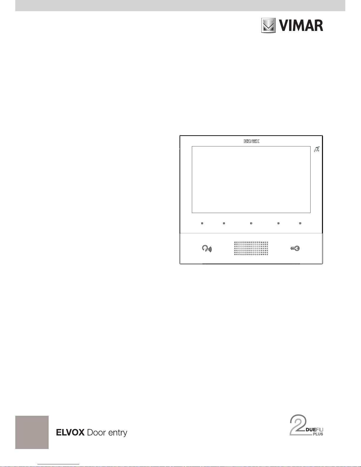
Wall-mount handsfree monitor for Due Fili Plus system with 7"
colour LCD display, capacitive keypad for entryphone functions
and intercom calls, induction loop for hearing aids, bracket for
xing in round or rectangular mounting box
The instructions manual can be downloaded from the website www.vimar.com
INSTALLATION RULES
Installation must be carried out in compliance with the current regulations regarding the installation of electrical
equipment in the country where the products are installed.
STANDARD COMPLIANCE
EMC directive
Standards EN 60065, EN 61000-6-1,EN 61000-6-3 and EN 60118-4.
WEEE - User information
The crossed bin symbol on the appliance or on its packaging indicates that the product at the end of its life must be
collected separately from other waste. The user must therefore hand the equipment at the end of its life cycle over to
the appropriate municipal centres for the differentiated collection of electrical and electronic waste. As an alternative
to independent management, you can deliver the equipment you want to dispose of to the dealer when purchasing a new
appliance of an equivalent type. You can also deliver electronic products to be disposed of that are smaller than 25 cm for
free, with no obligation to purchase, to electronics retailers with a sales area of at least 400 m
2
. Proper sorted waste collection for subsequent recycling, processing and environmentally conscious disposal of the old equipment helps to prevent
any possible negative impact on the environment and human health while promoting the practice of reusing and/or recycling
materials used in manufacture.
This product was developed using FreeRTOSTM software - http://www.freertos.org/
Page 3

3
TAB: 40505
EN
Description
Wall-mount Tab 7 monitor for Due Fili Plus system with 7" LCD colour display, loudspeaker for calls, capacitive keypad for entryphone functions (unlocking, self-starting, auxiliary services, volume, brightness and contrast controls) and intercom calls.
Desktop installation is possible with the desktop base accessory 40195 (sold separately).
Can be used by wearers of hearing aids.
Audio frequency function for hearing aids
The video entryphone can be used by people wearing hearing aids.
For correct functioning of the hearing aid, please refer to its instruction manual. Any metal objects or electronic
equipment in the vicinity may affect the quality of the sound received by the hearing aid.
Technical characteristics
• Wall-mounted, with metal bracket, in box: circular 2M (Vimar V71701), 3M (Vimar V71303, V71703) horizontal and vertical, 4+4M (Vimar V71318, V71718) and square, British standard.
• 7" LCD 16:9 display, resolution 800x480 pixels
• Minimum video signal level on the bus for reception: -20 dBm
• Capacitive touch keypad with backlit symbols.
• Powered from BUS terminals 1, 2 - nominal voltage 28Vdc
• Power consumption:
- in standby: 25 mA
- maximum current: 350 mA
• Ambient class: Class A1 (indoor use)
• IP30 protection rating
• Electronic ringer with 10 different melodies.
• Input for landing call.
• Dimensions: 165.8 x 184 x 24.2 mm
• DIP switch for line termination impedance.
Maintenance
Clean using a soft cloth. Do not pour water onto the appliance and do not use any type of chemical product.
Cleaning must be carried out either with the apparatus powered off (= disconnected from the bus) or after acti-
vating the keypad cleaning procedure (see the relative paragraph).
Warnings for the user
Do not open or tamper with the appliance.
In the event of faults, contact specialized personnel.
Page 4
4
TAB: 40505
EN
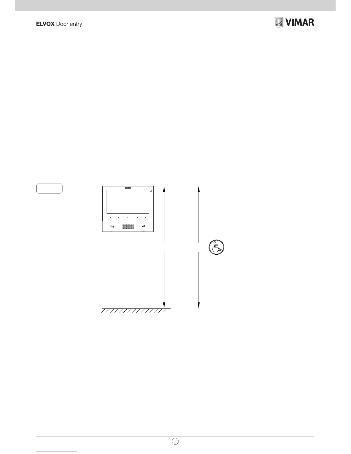
Fig. 1
1,60 / 1,65 m 1,20 m
Installation
Important: The device should be installed at a height of approximately 160 cm off the floor, taking care not
to expose it to direct sources of light so as to avoid annoying glare on the surface of the LCD screen.
Note: Fig. 1 shows the recommended installation distances, unless otherwise specified by current regula-
tions.
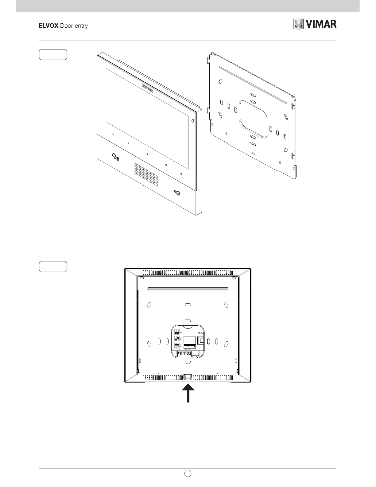
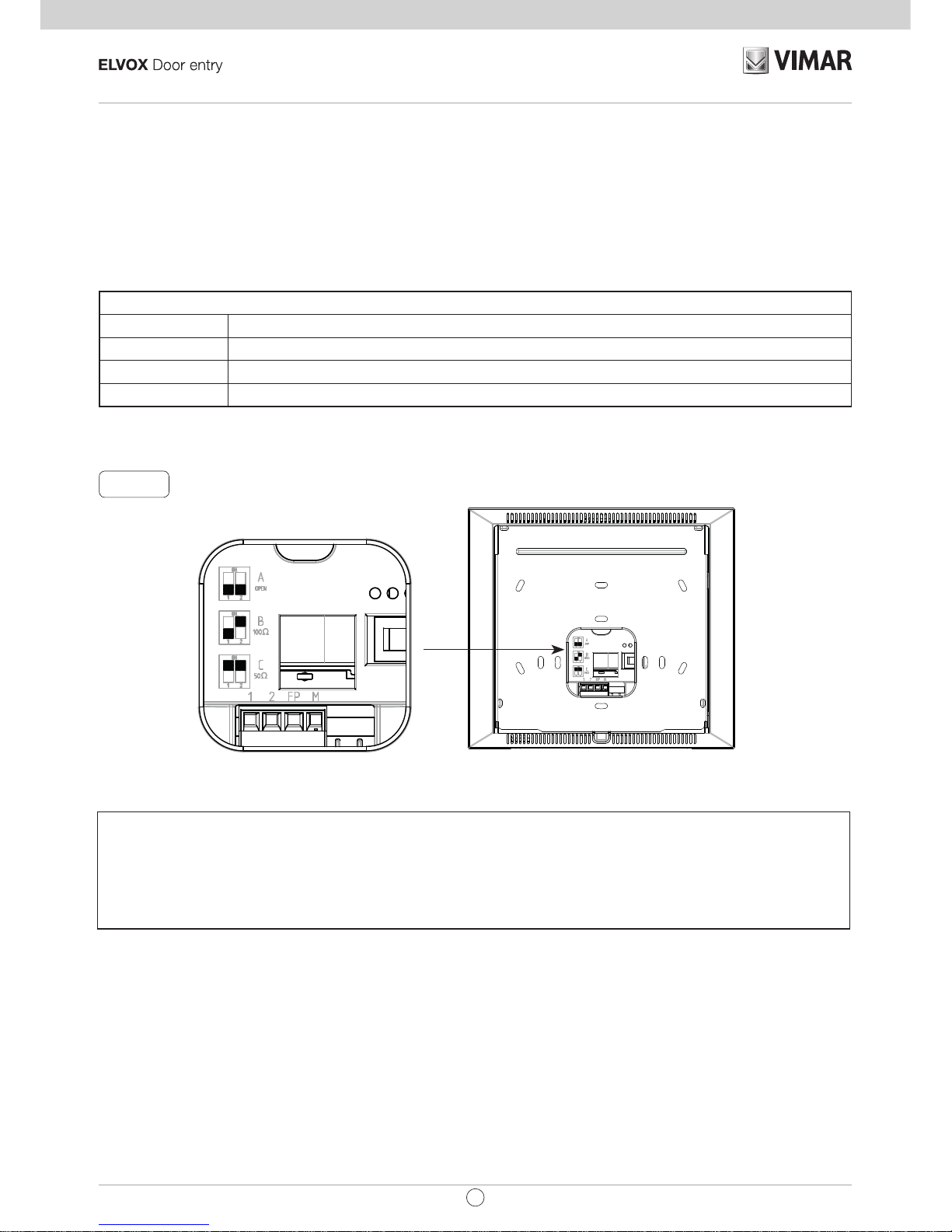
1. Secure the plate to the wall, with metal bracket, in box: circular 2M (Vimar V71701), 3M (Vimar V71303,
V71703) horizontal and vertical, 4+4M (Vimar V71318, V71718) and square, British standard.
2. Wire the terminal block (Fig. 5).
3. Terminate the video signal (Fig. 6)
4. Install the video entryphone as follows: position the video entryphone on the plate keeping it slightly
raised. While keeping the front panel pressed, apply a light downward pressure until it clicks into place.
5. Should you need to remove the monitor you need to apply a light pressure on the lever (Fig. 3) and raise
it (from the bottom upwards) so as to release the monitor from the chassis.
Page 5
5
TAB: 40505
EN
Fig. 2
Fig. 3
Page 6
6
TAB: 40505
EN
Fig. 5
Connections
On the rear there is a terminal board for:
• Connection of the Due Fili Plus bus
• The Landing Call input. The maximum connection distance is 10 m. When suitably programmed using
SaveProg, this input can be used for the Alert function. See the relative paragraph.
Note: Art. 40505 does not have terminals for an additional power supply. For this reason, if the section of the
Due Fili bus in which the internal unit is located is busy with another call/conversation, or another 40505 is
switched on for any reason, regardless of its operating status, it will not be possible to switch on a second
40505 and a tone will sound to warn the user. The only possible action is to operate the lock using the dedi-
cated button, provided it is not congured for other functions; the Alert function can be used as described in
the relative paragraph.
Connection terminal block
Terminals Function
1, 2 DUE FILI PLUS digital bus.
FP Landing Call button input (terminal M reference).
M Reference earth
Page 7
7
TAB: 40505
EN
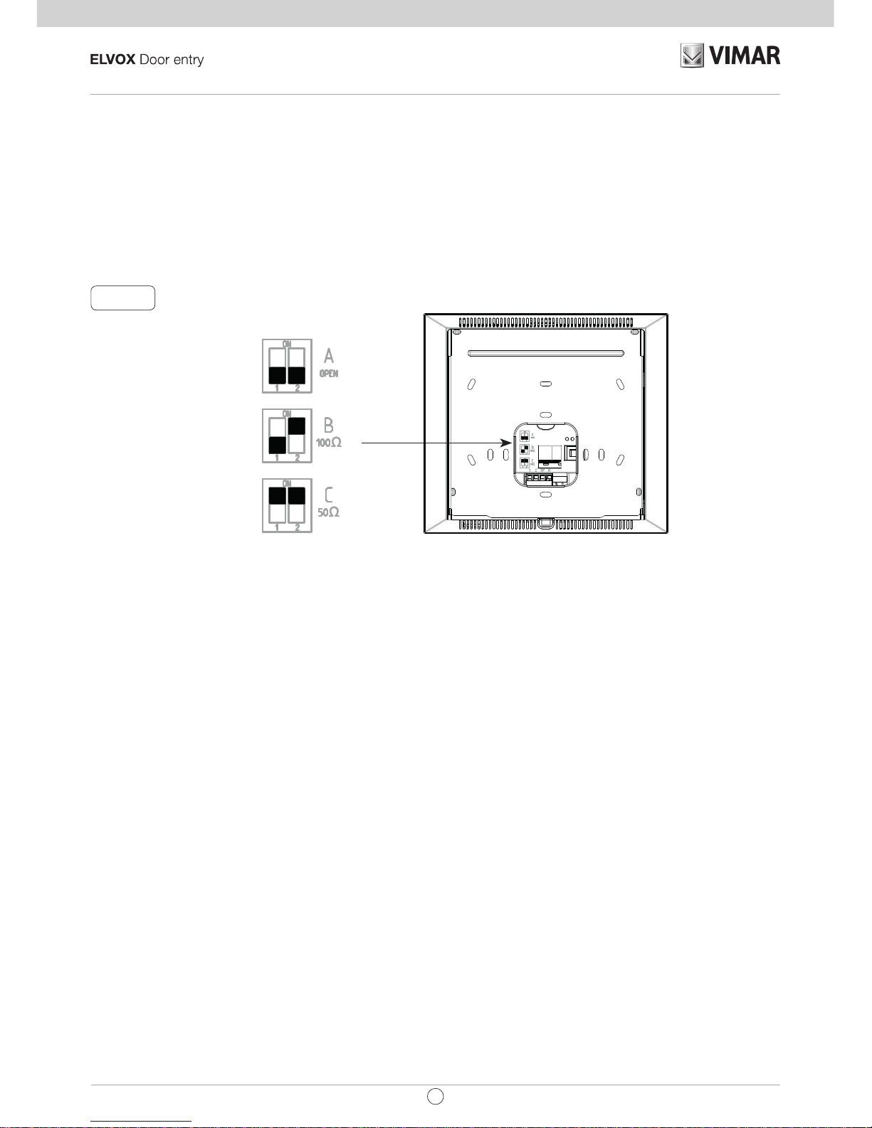
Video Termination
Select DIP switch to terminate the video signal
A) if the BUS cable enters terminals 1, 2 and continues to another internal unit.
B) when a BUS cable with a characteristic impedance of 100 Ohms (Elvox 732I or 732H cable) enters ter-
minals 1, 2 and the riser stops in the internal unit
C) when a BUS cable with characteristic impedance of 50 Ohms (Cat. 5 or Cat. 6 twisted pair cable) enters
terminals 1, 2 and the riser stops in the internal unit.
Fig. 6
Page 8
8
TAB: 40505
EN
Connecting the internal unit art. 40505 in the in/out configuration
Cable riser
In/out wiring diagram
Wiring diagram with cable terminating in the internal unit
Variant for connecting the landing or alert button
Connecting the FP/M terminal
2
1
FP
M
2
1
FP
M
K
C
50Ω
B
100Ω
A
OPEN
ON
12
ON
12
ON
12
C
50Ω
B
100Ω
ON
12
ON
12
Termination to apply
Termination to be applied depending on the characteristic impedance of the cable
2
1
FP
M
Cable riser
Connecting the internal unit art. 40505 in terminal conguration
Page 9
9
TAB: 40505
EN
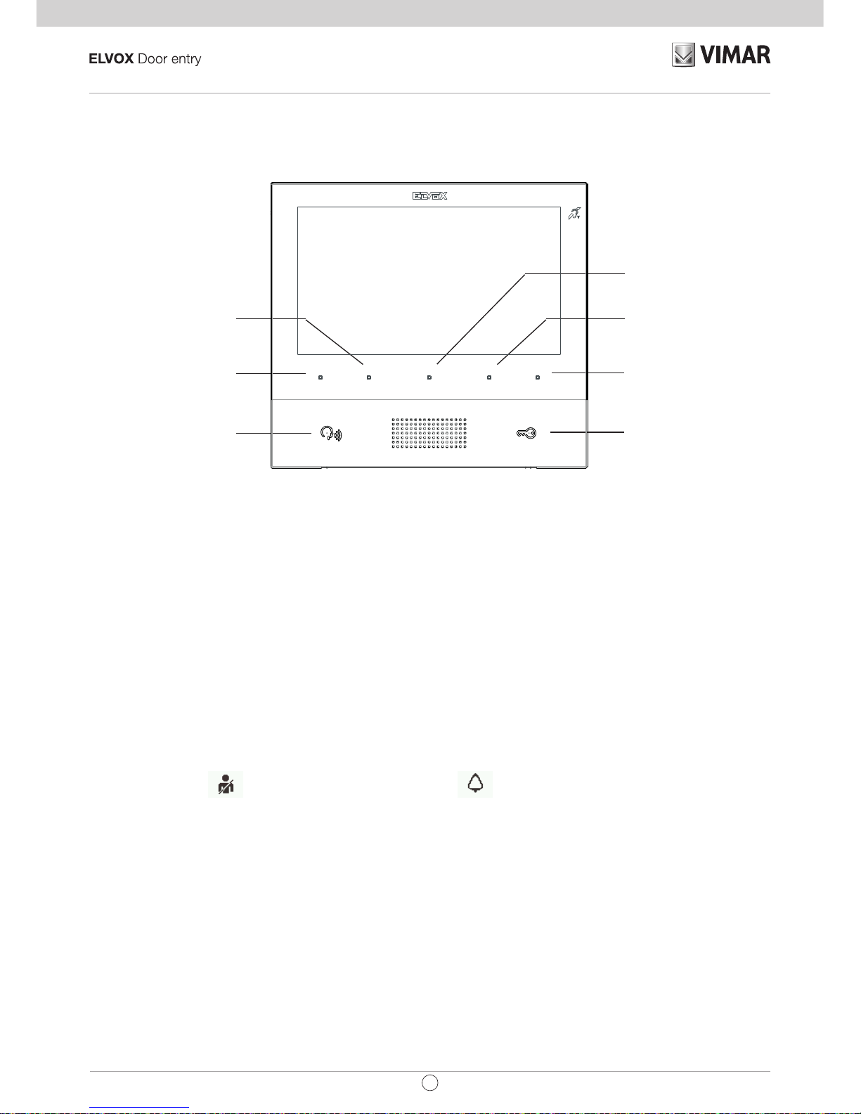
Key functions
In the subsequent sections of this document the touch keys are designated as shown in the gure below:
T3 (F1)
P/A (ANSWER / END
CONVERSATION)
T4 (USER ABSENT /
MUTE MICROPHONE)
M (ACCESS
CONFIGURATION)
DOOR LOCK
T2 (STAIR LIGHT)
T1 (SELF-START)
Keys T1..T4 have two operating contexts:
• Operators
• Intercom
In the Operators context, keys T1..T4, have the default function (when not programmed) indicated in the gure
above. They can only be programmed using SaveProg.
In the Intercom context keys T1..T4 are not programmed by default. They can be programmed from the installer
menu or using SaveProg.
T4 has the functions user absent / mute microphone only when it is not programmed. If T4 is used for a Operators function, the default function will be lost and it will not be possible to assign it to any other key. If T4 has
the default function, the associated LED will operate also as an indicator for :
• User absent (the internal unit rejects the call from an external unit and consequently the call is unsuccessful)
• Ringer disabled (the internal unit does not ring for calls from the external unit, but otherwise functions
normally)
essential when the display is switched off. It remains on, switching off briey for 1, 2, 3 or a maximum of 4 times
each cycle, according to the number of calls received when user absent is activated. If the user absentfunction
is absent, the icon
is displayed at the top and on T4 to indicate that T4 will re-activate the ringer.
If the ringer disabled function is activated (see User Conguration), no icon is associated with T4 because
ringer disabled has priority over user absent.
The M key cannot be programmed and its function is context-dependent.
The P/A key also has the function of activating the Intercom, if there is at least one programmed key or if ag
7 in SaveProg is activated (default) (Switchboard mode).
By default, the LOCK key, as in all internal units, controls the lock of the last external unit to make a call or
the external unit for which self-start procedure was performed. It can only be programmed using SaveProg.
The LED associated with the LOCK key indicates door open status of the system, essential when the display
is switched of, even if the same key is programmed for another function. It can also indicate the status of the
Alert, described later in this manual.
In standby mode, the screen is completely switched off. Touching any of the keys T1..T4, M, P/A (only if it has a
function) turns on the display, but without executing any function. If the LOCK key is set to its default function, the
function is executed without switching on the display. If the key has been programmed, no function is executed
but the display is switched on, as with the other keys.
Page 10
10
TAB: 40505
EN
First power up
The 40505 leaves the factory without an ID, as do all other internal units (except kits). On switching on the display
by touching the keypad, the only action possible is to assign main
or secondary internal unit as the ID:
First power up
On choosing one of the two, the internal unit requests ID assignment from the Master external unit and the
functions of the keys change as follows:
Initialisation in progress
T1
now serves to cancel a request, T3 and T4 serve respectively to reduce and increase the
speaker volume.
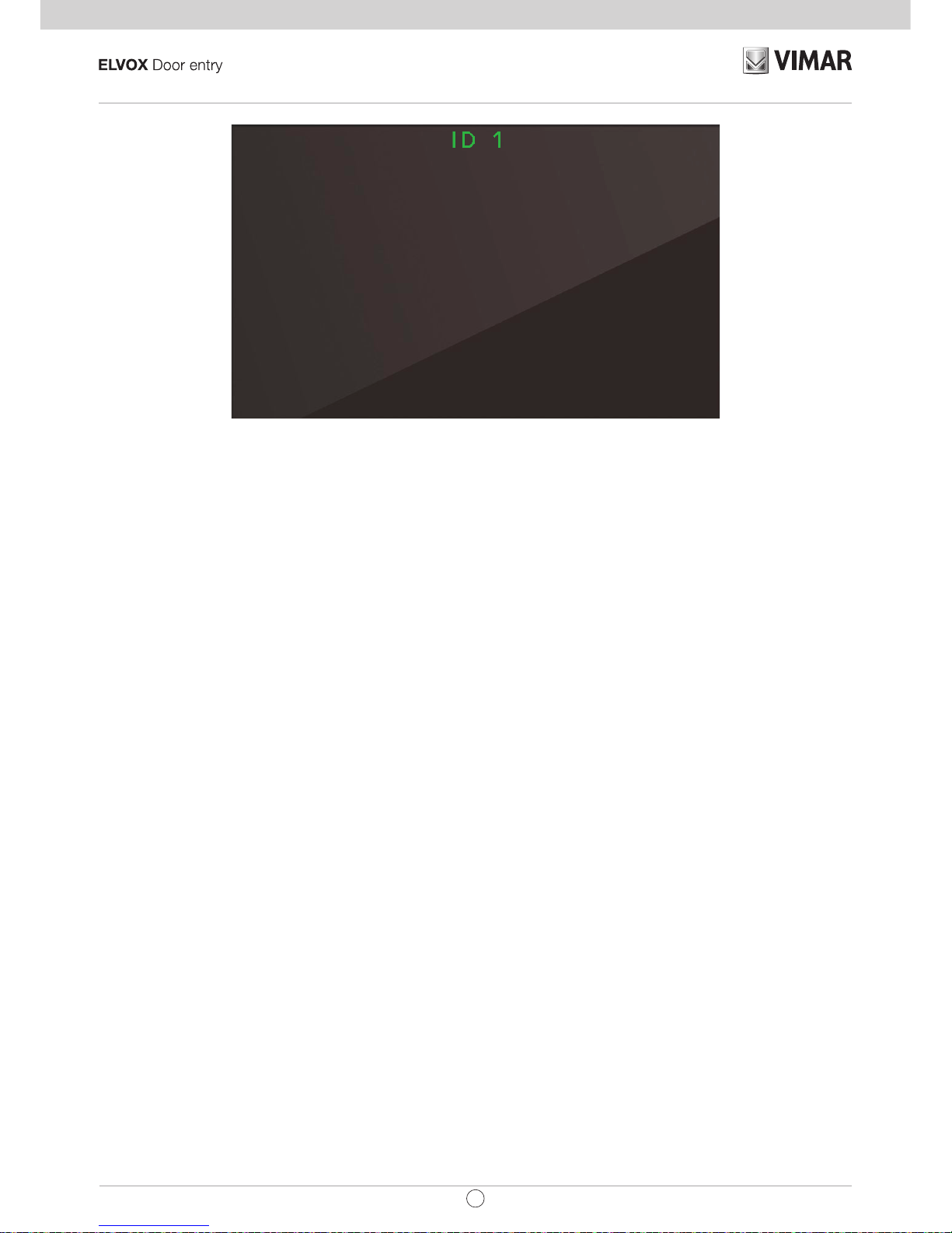
On completion of the ID assignment procedure, the number assigned will appear at the top of the display:
Page 11
11
TAB: 40505
EN
Assigning ID
Page 12
12
TAB: 40505
EN
After ID assignment
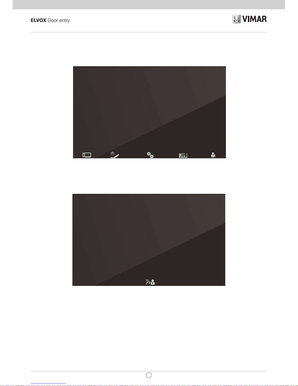
Once the ID has been assigned, the display, when woken up, appears as follows:
Main screen
The P/A key toggles between the context displayed (Operators) and Intercom:
Intercom context
If the P/A key is touched when the internal unit is in standby mode, the unit will wake up in the Intercom
con-
text. By default, it is only possible to call, with the M key, a generic porter switchboard. Using the programming
procedure described below, it is possible to add up to four other intercom calls, which can also be to specic
porter switchboards.
Page 13
13
TAB: 40505
EN
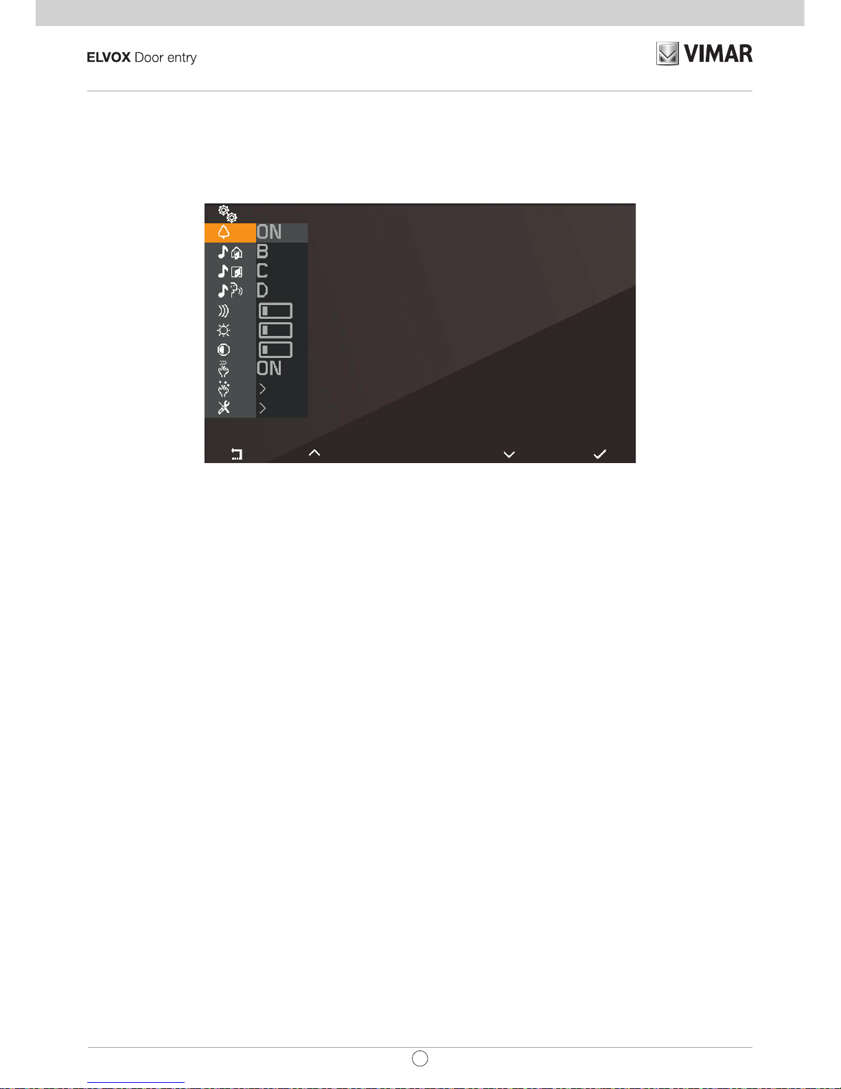
User conguration
Touching the M key while in the Operators context opens the user conguration menu. In all the menus, naviga-
tion is circular, i.e. scrolling down past the last option in any menu takes you back to the rst option.
User conguration menu
T1 returns you to the Operators context, while T4takes you to the highlighted conguration option.
Page 14
14
TAB: 40505
EN
Ringer mute
Use and to enable/disable the ringer of the internal unit, for calls from PE, as follows:
•
: (ringer enabled)
•
: (ringer disabled) The internal unit does not ring, but otherwise functions normally.
•
: (user absent) The internal unit does not ring and does not switch on. With conguration via
SaveProg (ag 22 ACK. Grp. Excl. S) it is possible to ring secondary ringers, otherwise the call from
external unit is rejected and unsuccessful.
When the ringer is disabled, the icon
will appear at the top of the screen. In the case of 'user absent', the
icon
is displayed. 'User absent' is the same function assigned by default to T4 when the internal unit is
in standby mode.
The ringer mute function does not apply to calls received from an internal unit or porter switchboard.
Press T4
to conrm, T1 to cancel without saving.
Note: in the remaining part of this manual, it is assumed that the functions of T1 and T4 are understood.
Default: ringer enabled.
Page 15
15
TAB: 40505
EN
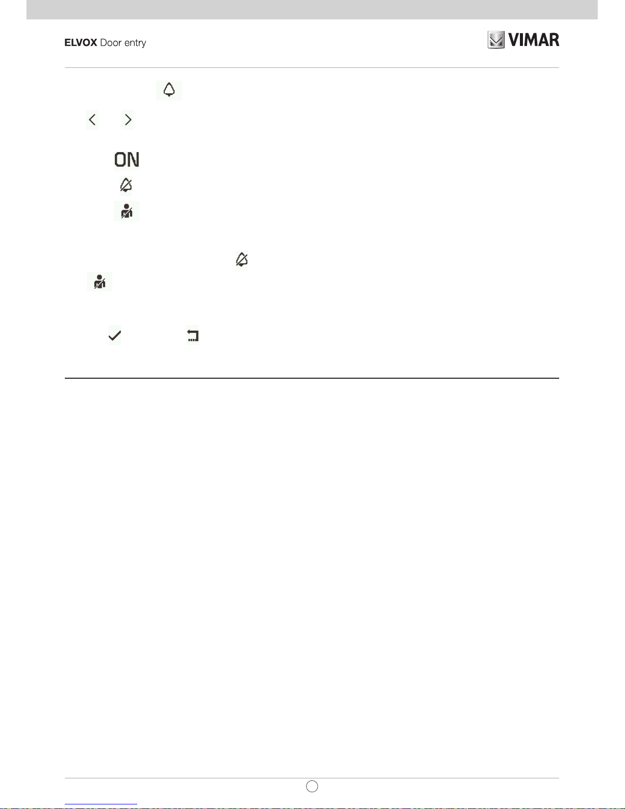
Select melody for calls from external unit
Use and to select one of the 10 available melodies (identied by letters A to J) to use as a ringtone for
calls from the external unit. The internal unit plays back the selected ringtone.
Default: melody B.
Select melody for call from external unit
Conrm melody for call from external unit
Page 16
16
TAB: 40505
EN
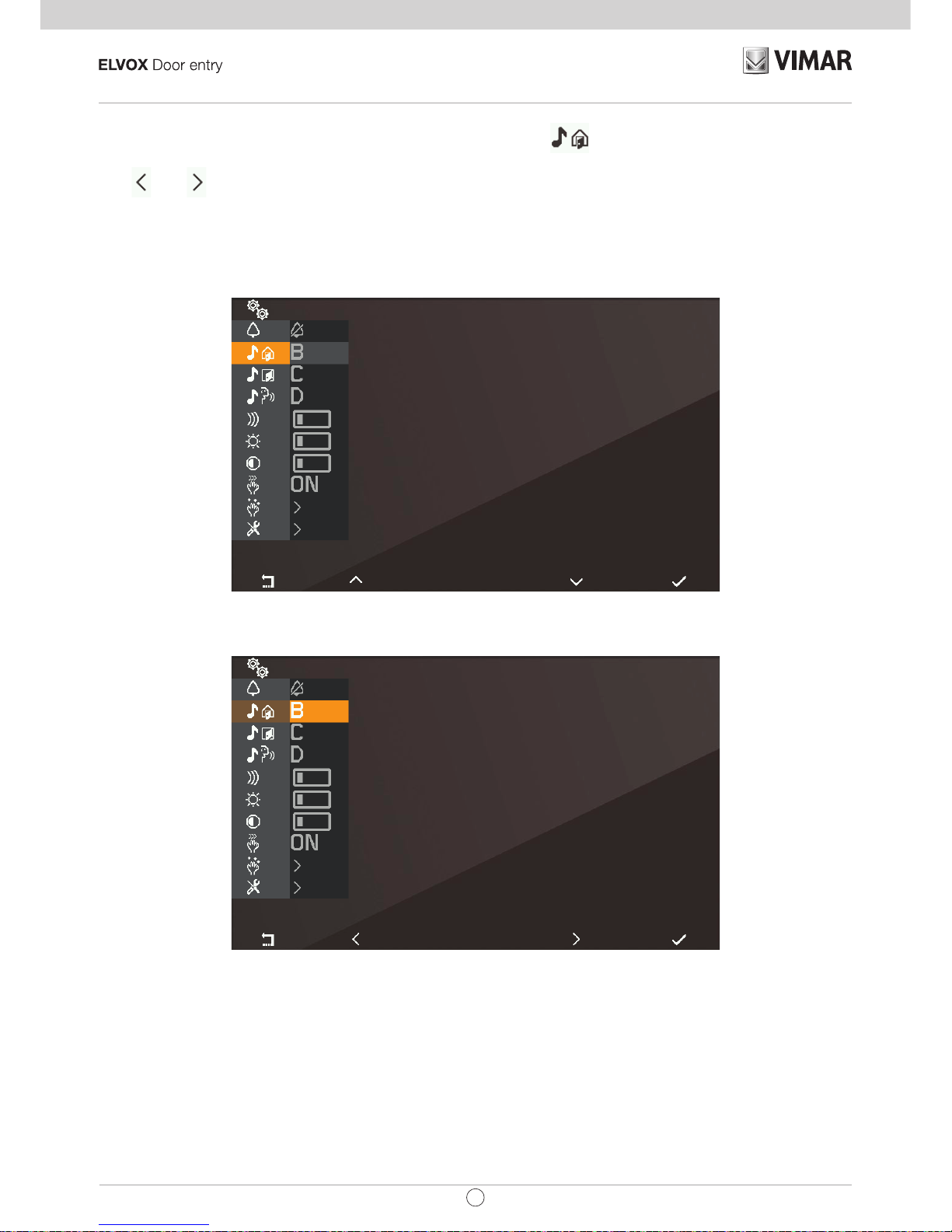
Select melody for calls from landing
Use and to select one of the 10 available melodies (identied by letters A to J) to use as a ringtone for
calls from the landing. The internal unit plays back the selected ringtone.
Default: melody C.
Select melody for call from landing
Conrm melody for call from landing
Page 17

17
TAB: 40505
EN
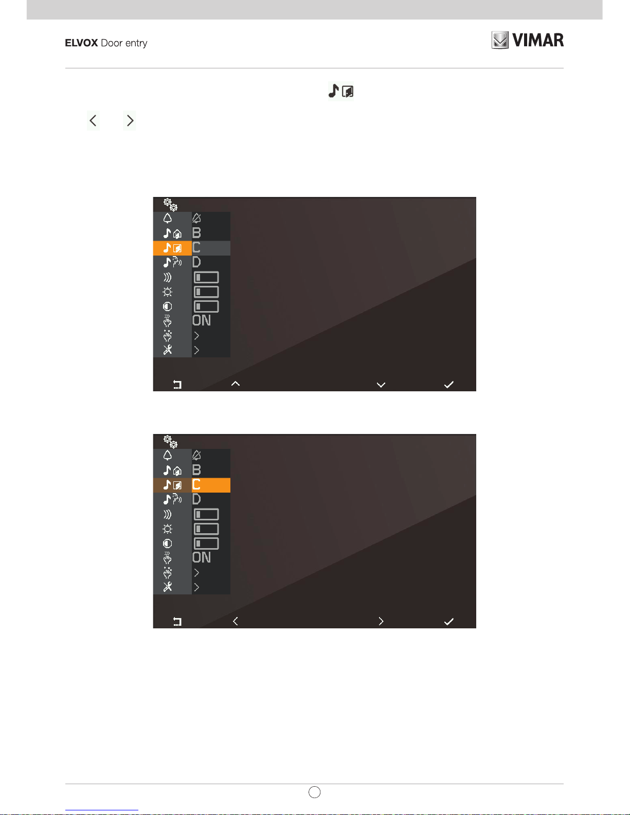
Select melody for calls from internal unit or switchboard
Use and to select one of the 10 available melodies (identied by letters A to J) to use as a ringtone for
calls from an internal unit or switchboard. The internal unit plays back the selected ringtone.
Default: melody D.
Select melody for call from internal unit or switchboard
Conrm melody for call from internal unit or switchboard
Page 18

18
TAB: 40505
EN
Ringer volume control
Use and to increase/decrease the ringer volume, which is indicated by the horizontal bar.
NOTE: the level set is used for all ringtone types (calls from the external unit, landing, internal unit or switchboard).
Default: level 5.
Select ringer volume control
Ringer volume control
Page 19

19
TAB: 40505
EN
Brightness control
Use and to increase / decrease the brightness of the video signal from an external unit, the level of which
is indicated by the horizontal bar. The internal unit automatically requests the Master external unit to perform a
self-start procedure so that the user can see the effect of the brightness control.
NOTE: the level set is used for all external units.
Default: level 5.
Select brightness control
Brightness control
Page 20

20
TAB: 40505
EN
Contrast control
Use and to increase / decrease the contrast of the video signal from an external unit, which is indicated
by the horizontal bar. The internal unit automatically requests the Master external unit to perform a self-start
procedure so that the user can see the effect of the contrast control.
NOTE: the level set is used for all external units.
Default: level 5.
Select contrast control
Contrast control
Page 21

21
TAB: 40505
EN
Key tones
Use the keys and to enable/disable the tone produced whenever a key is touched (keystroke feedback).
Default: enabled
Key tone
Key tone
Page 22

22
TAB: 40505
EN
Keypad cleaning
Activates the keypad cleaning function:
Keypad cleaning activation
The keypad cleaning procedure lasts 20 seconds and this time period cannot be extended by pressing the
keys, which remain disabled until the keypad cleaning procedure is completed.
Page 23

23
TAB: 40505
EN
Installer conguration
To access the installer menu , you must enter the 3-digit code (PIN). The default PIN is 000, but this can be
changed as described below. The PIN is entered using the following keys:
• T1
to cancel the last digit, provided that the cursor is on the second or third digit, otherwise use
to return to the user conguration menu.
• T2
to change the digit highlighted in colour in the sequence 0 – 9 – 8 … – 2 – 1 – 0 …
• T3
to change the digit highlighted in colour in the sequence 0 – 1 – 2 … – 8 – 9 – 0 …
• T4
to conrm the selected digit, and after the third digit, if the PIN entered is correct, to access the
installer conguration procedure. If the PIN is not correct, you are returned to the user conguration
menu.
Note: once the correct PIN has been entered and you have returned to the user menu, it will not be necessary
to enter the PIN again to access the installer menu, until the internal unit returns to standby mode.
Entering the PIN
Page 24

24
TAB: 40505
EN
Entering the PIN
Entering the PIN
Installer menu
Page 25

25
TAB: 40505
EN
Selection of key icons in the Operators context
With the option you can change the icons that appear above the keys in the Operators context. The
default setting is blank:
Selection of key icons in the Operators context
Which means that the preset icons i.e., those which rst appear, will be used. When assigning icons starting
from the default setting, touching T4
opens the following menu:
On conrming with T4 , a list of selectable icons appears:
Page 26

26
TAB: 40505
EN
Selection of key icons
If an icon has already been assigned, an option will be added to the specic menu that allows you to cancel the
assigned icon and replace it with the default icon.
Selection of key icons
This operation must be conrmed:
Page 27

27
TAB: 40505
EN
Conrm icon cancellation
To change an icon, you do not need to cancel it rst, just simply replace it with a new icon.
Page 28

28
TAB: 40505
EN
Intercom
With the option you can change the IDs of internal units or porter switchboards to be used in the Intercom context. The default setting is blank:
Intercom menu
Each line corresponds to one of the four keys in the Intercom
context. On selecting one of these four options,
a sub menu opens:
Selection of intercom type
The three options that appear are:
•
to associate an internal unit with the selected position.
•
to associate a porter switchboard with the selected position.
•
to associate the Alert function with the selected position.
Page 29

29
TAB: 40505
EN
• to cancel the association with the selected position (visible only if the position is programmed).
Association of an internal unit
Selection of intercom type
In this condition, on the internal unit that is to be called, press a key that can be identied unequivocally. It
is advisable to use a key that controls opening of a lock, but you can also use a key that operates a relay or
controls one of the F1 or F2 outputs of an external unit. If the internal unit that is to be called has a handset, it
is advisable to use the lock with the handset replaced.
Once the association has been made, the basic menu of the Intercom context will appear as follows (the internal
unit to be called is number 4):
Awaiting association of the internal unit to be called
Association of a porter switchboard
Page 30

30
TAB: 40505
EN
Selection of the switchboard to be called
Select the porter switchboard you wish to assign to the previously selected key in the Intercom context and
conrm. The basic menu of Intercom context will appear as follows:
Selection of the switchboard to be called
Association of the Alert function
On conrming the function, the Alert function is immediately assigned to the previously selected key in the
Intercom context:
Page 31

31
TAB: 40505
EN
Cancelling an association
Awaiting conrmation of intercom cancellation
Conrm or cancel removal of the association between previously selected key in the Intercom context.
Page 32

32
TAB: 40505
EN
Assignment of main and secondary ID
For descriptions of these procedures, refer to the beginning of the paragraph First power up.
Changing the PIN
To change the PIN, follow the same procedure as that used to enter it to access the installer conguration menu.
The following example shows how to set the PIN to 123:
Touch
Touch
Touch
Touch 2 times
Page 33

33
TAB: 40505
EN
Touch
Touch 3 times
Touch
The PIN has now been changed to 123.
Page 34

34
TAB: 40505
EN
Reset factory conguration
This procedure allows you to cancel any settings and programming of the internal unit and to restore it to the
original default condition. The system asks for conrmation that you wish to proceed with the reset:
Selection of Reset factory conguration
Awaiting conrmation of Reset factory conguration
From this moment, the internal unit is in the First power up condition.
Page 35

35
TAB: 40505
EN
System information
From this menu, useful information can be obtained for Vimar customer service (SAC / TSX), including ID,
Firmware version, etc.:
System information
Information display
• The information reported, from the top downwards, is as follows:
• ID of the internal unit
• FW version
• Bootloader version
• UID
• FW compilation date and time
• Available memory – FreeRTOS version used
Page 36

36
TAB: 40505
EN
Programming with SaveProg
SaveProg manages Art. 40505 from version 3.3.2.1 onwards. The correspondence between the
keys P1..P8 of SaveProg and the keys T1..T4 in the two operating contexts is as follows:
KEY OPERATORS INTERCOM
T1 P1 P3
T2 P2 P4
T3 P7 P5
T4 P8 P6
The LOCK key corresponds to P0.
Page 37

37
TAB: 40505
EN
Call to internal unit (outgoing)
Note: before connecting the audio channels with any other device, the internal unit Art. 40505 determines
the best possible communication parameters. During this stage, which lasts approximately 1 second,
a waiting tone is transmitted to the user.
To make a call to another internal unit, at least one call must be programmed as described above.
No specic programming is required for a generic porter switchboard.
The gure below shows the situation when all the keys are programmed. This operating context, designated
Intercom, is obtained by touching the P/A key when in standby mode or by switching from the Operators
context, also by touching P/A.
Call to internal unit
T1 and T4 make a call to an internal unit, T2 and T3 call two specic porter switchboards, M call a generic
porter switchboard.
The call is initiated by touching one of the above keys. Before the call is answered, the display changes to the
following:
Page 38

38
TAB: 40505
EN
The icons at the top left of the display indicate that a call is being made to the internal unit programmed as T1.
While waiting for an answer, you can press T2 and T3. On receiving an answer, the display changes to:
The centre key, now , and T4 are enabled. gives access to the context Audio only settings.
T4 has the function of microphone mute
or enable .
The Audio only settings context allows loudspeaker volume control only.
Page 39

39
TAB: 40505
EN
The T1 and T2 keys turn grey respectively when the minimum and maximum levels are reached.
The centre key, now
, allows you to return to the previous context.
The conversation can be ended with the P/A key or by the internal unit to which the call was made using the
appropriate procedure.
Page 40

40
TAB: 40505
EN
Call from internal unit (incoming)
On receiving a call from another internal unit, the display appears like this:
Incoming call from internal unit
The number at the top left indicates the position of the caller in the list of keys in the Intercom context. If the
caller is not present in the list, no number will be displayed.
Call from internal unit not belonging to the intercom context
If the caller is a switchboard, different icons appear at the top left of the display:
Page 41

41
TAB: 40505
EN
Call from switchboard 1
For incoming intercom calls, it is not possible to mute the ringer before a call is received. It is only possible to
mute the ringer for the current call. Once muted, the ringer cannot be switched back on during the current call,
so the icon disappears.
The call is answered using the P/A key, after which the situation is the same as with an outgoing call.
The conversation can be ended using the P/A key or by the calling internal unit using the appropriate procedure.
Page 42

42
TAB: 40505
EN
Switchboard scenarios
If the unit either making or receiving the call is a porter switchboard, there are other possible scenarios. For
example, the switchboard operator could connect an internal unit to another internal unit, to an external unit or
to a second porter switchboard.
If the switchboard operator already has the other internal unit, external unit or switchboard on hold, he/she will
connect it directly.
Alternatively, he/she could put this internal unit on hold while carrying out the necessary operations to call the
other party. The switchboard operator can only connect an external unit to the internal unit if the external unit
is already on hold:
Internal unit connected to external unit
During the wait, the internal unit will emit a specic tone. The internal unit can also cancel the wait by putting
the internal unit in standby mode using the P/A key.
Internal unit put on hold
During the wait, the microphone is obviously muted and will remain as such also when the switchboard operator
connects the the internal unit to the other party, which means that, once connected, it will be necessary to use
Page 43

43
TAB: 40505
EN
T4 to re-enable the microphone. Alternatively, you can also use T4 before the new connection is made.
In this case the microphone will already be enabled. Given that it is not possible to know beforehand the exact
moment at which the switchboard operator will connect the internal unit to the other party, this strategy has been
chosen in order to ensure that the other party hears nothing unless at the explicit request of the party waiting.
Internal unit connected to another internal unit
Internal unit connected to a porter switchboard
The conversation will proceed as if held directly between the internal unit and the other party.
Page 44

44
TAB: 40505
EN
Call from external unit (incoming)
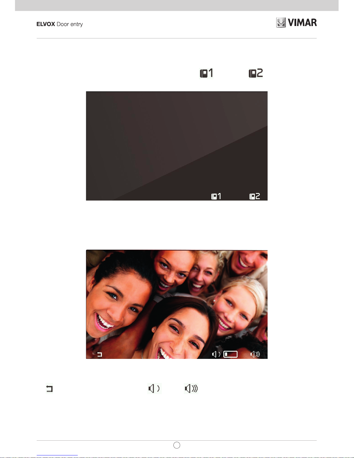
On receipt of a call from an external unit, the display can appear in two different ways, depending on whether
the call is coming from an audio only or from an audio/video external unit:
Call from external unit (incoming), Audio
Call from external unit (incoming), Video
Note: the display of internal unit Art. 40505 switches on on receiving a call from an external unit to display the
signal of the external unit in accordance with its own programming, as indicated in the table below.
Page 45

45
TAB: 40505
EN
CALL FROM VIDEO EXTERNAL UNIT FLAG 1 (MONITOR ON) RESULT
Direct
ACTIVE Switches on
NOT ACTIVE Does not switch on
Indirect (belongs to a group with only one
secondary unit)
ACTIVE Switches on
NOT ACTIVE Does not switch on
Indirect (belongs to a group with at least two
secondary units)
ACTIVE Does not switch on
NOT ACTIVE Does not switch on
Note: The secondary internal units ring at a reduced, xed volume (level 2 out of 10).
On answering, the display switches on to show the video from the external unit calling.
T4, with the icon
, allows you to mute the ringer for the call currently in progress. Once muted, the ringer
cannot be switched back on during the current call, so the icon disappears.
Before answering, if the display is showing the video signal from the external unit, you can adjust the brightness
by accessing the the Video only settings with
:
Video adjustments
If the call originates from an audio external unit, it will not be possible to make any adjustments.
The T3
and T4 keys turn grey respectively when the minimum and maximum levels are reached.
The centre key, now
, allows you to return to the previous context.
Before answering, whatever condition the internal unit is in, it is possible to use the Operators context or the
LOCK key, unless programmed for another function.
To answer the call, use the P/A
key.
Page 46

46
TAB: 40505
EN
Answering an audio call
Answering a video call
As in a conversation with an internal unit, T4 has the function of muting
or re-enabling the microphone.
After answering, it is possible to use the Operators context or the LOCK key, unless programmed for another
function.
During the conversation, the
key serves to enter the Audio only settings context if the call originates from
an audio external unit or Audio and video settings context if the call originates from an audio/video external unit.
Page 47

47
TAB: 40505
EN
Audio settings
Audio/video settings
The T1 and T3, T2 and T4 keys turn grey respectively when the minimum and maximum levels are reached.
The conversation can be ended using the P/A key or by the calling external unit in the appropriate manner.
Page 48

48
TAB: 40505
EN
Self-start
The self-starting of an external unit is performed with the audio signal relayed from the external unit to the internal
unit activated so that from the internal unit, the user can hear but not be heard:
Self-start activation
As can be seen from the icon on T4, the microphone of the internal unit is muted. It can be enabled or muted
again by touching the T4
key. The P/A key interrupts conversation regardless of whether the microphone is
enabled or muted.
During self-start, it is possible to use the Operators context or the LOCK key, unless programmed for another
function.
The
key gives access to the Audio only settings context if the call originates from an audio external
unit or Audio and video settings context if the call originates from an audio/video external unit.
The conversation can be ended using the P/A key or from the external unit, using the appropriate procedure.
Page 49

49
TAB: 40505
EN
Alert
Internal Unit Art. 40505, together with porter switchboard Art. 40510, creates a system that can send an alert to
the switchboard operator even when the Due Fili bus is busy.
To activate this service:
1. Program using SaveProg or the same Internal Unit one of the T1..T4 keys in the Intercom context
to perform the Alert function (managed internally by the unit as an intercom call to itself). The icon
displayed is
. More than one key may be programmed to perform the same function, but the
results will be indistinguishable.
2. It is possible to use the pair of terminals FP-M as a remote input for the Alert function.. Their use
does not preclude programming of T1..T4, and vice versa, but the landing call function will be lost.
The FP-M operating mode is selected using SaveProg, ag 31 (F.P. <-> Alert). Closing the terminals
FP-M has the same operational effect as that described below for the T1..T4 keys .
3. Enter the Intercom
context.
4. Touch one of the previously programmed keys.
5. The Internal Unit sends the alert.
This is what happens then:
6. The Internal Unit waits to receive the alert from the switchboard. In the meantime, the LED on the
LOCK key ashes with the cadence 0.5 s on / 0.5 s off. On receipt of the message, the switchboard
emits a double beep and displays a red envelope icon to alert the operator.
7. If it does not receive a replay, the Internal Unit resends the message every 10 s. After 5 attempts with
no reply the Internal Unit stops sending the messages.
8. When the Internal Unit receives conrmation that the switchboard has received the message, the
LED on the LOCK key ashes with the cadence 0.1 s on / 0.1 s off. Normally the time between the
sending of the request and conrmation of reception is less than a second.
9. Until the switchboard calls the Internal Unit to service the request, the Internal Unit resends the
message every 120 s. At each message, the switchboard emits two meets and increases count of
messages received. The counter can be viewed by opening the list of alerts in the switchboard. The
sending of messages never terminates. It continues until the end of the service described in the next
point, unless the switchboard is powered off or removed from the system, in which case the Internal
Unit, after 5 unsuccessful attempts starting from the rst timeout of 120 s, will return to standby mode
and the LED on the LOCK key will stop ashing.
10. If the operator calls the Internal Unit starting from the list of alerts (and only if the call is made from
this list) a message is sent via the bus to the Internal Unit to terminate its internal procedure, and
consequently the LED on the LOCK key will stop ashing.
Note: the LED on the LOCK key may be on beforehand or may request to be switched on during the alert pro-
cedure due to a door being opening in the Due Fili system. The ashing has priority over this condition, and on
completion of the procedure, the LED on the LOCK key will either stay on or off according to whether or not a
door is open in that moment.
If the bus is engaged in another conversation or by another 40505 already powered on, the Intercom context
is inaccessible. If at least one of the T1..T4 keys is programmed as the Alert function, then LEDs relative to this
function will ash for 10 s while waiting for the user to touch any one of these keys. No other keys are enabled and
the display is not switched on. Once the function has been initiated, all the LEDs of the Alert function will switch
off and the Internal Unit will return to standby mode; in any case, the Internal Unit will return to standby after 10 s.
Page 50

50
TAB: 40505
EN
Updating the FW
WinBoot manages Art. 40505 from version 7.2.1.3 onwards.
PC Drivers
The drivers are the same as for the other device in the TAB family. The rst time a device is connected to a
USB port, the PC must associate the drivers to the peripheral device even if a TAB device has already been
associated. The internal unit is identied at the level of WinBoot / SaveProg, as ELVOX_40505A:
Page 51

51
TAB: 40505
EN
Page 52

Viale Vicenza 14
36063 Marostica VI - Italy
www.vimar.com
49400914A0_MU_EN 00 1710
 Loading...