

Page 1
01923 - 01924
Attuatore/ricevitore RF - Istruzioni
RF actuator/receiver - Instruction handbook
Actuateur/récepteur RF - Notice technique
Aktor/Empfänger RF - Montageanweisungen
Actuador/receptor RF - Manual de Instrucciones
Εκκινητής/δέκτης RF - Οδηγίες χρήσης
CLIMA
Page 2

Page 3
01923 - 01924
ITALIANO
Attuatore/ricevitore RF . . . . . . . . . . . . . . . . . . . . . . . . . . . . . . . . . . . . . . . . . . . . . . . . . . . . . . . . . . . . . . . . . . . . . . . . 1
ENGLISH
RF actuator/receiver . . . . . . . . . . . . . . . . . . . . . . . . . . . . . . . . . . . . . . . . . . . . . . . . . . . . . . . . . . . . . . . . . . . . . . . . . . 11
FRANÇAIS
Actuateur/récepteur RF . . . . . . . . . . . . . . . . . . . . . . . . . . . . . . . . . . . . . . . . . . . . . . . . . . . . . . . . . . . . . . . . . . . . . . . 21
DEUTSCH
Aktor/Empfänger RF . . . . . . . . . . . . . . . . . . . . . . . . . . . . . . . . . . . . . . . . . . . . . . . . . . . . . . . . . . . . . . . . . . . . . . . . . . 31
ESPAÑOL
Actuador/receptor RF . . . . . . . . . . . . . . . . . . . . . . . . . . . . . . . . . . . . . . . . . . . . . . . . . . . . . . . . . . . . . . . . . . . . . . . . . 41
ΕΛΛΗΝΙΚΑ
Εκκινητής/δέκτης RF . . . . . . . . . . . . . . . . . . . . . . . . . . . . . . . . . . . . . . . . . . . . . . . . . . . . . . . . . . . . . . . . . . . . . . . . . . 51
Page 4

Page 5

INDICE.
1. Descrizione . . . . . . . . . . . . . . . . . . . . . . . . . . . . . . . . . . . . . . . . . . . . . . . . . . . . . . . . . . . . . . . . . . . . . . . . . . . . . . . . . . . . . . . . . . . 2
2. Funzionamento . . . . . . . . . . . . . . . . . . . . . . . . . . . . . . . . . . . . . . . . . . . . . . . . . . . . . . . . . . . . . . . . . . . . . . . . . . . . . . . . . . . . . . . . 2
3. Configurazione cronotermostati 01910 . . . . . . . . . . . . . . . . . . . . . . . . . . . . . . . . . . . . . . . . . . . . . . . . . . . . . . . . . . . . . . . . . . . . . . 2
4. Configurazione cronotermostati 01911 . . . . . . . . . . . . . . . . . . . . . . . . . . . . . . . . . . . . . . . . . . . . . . . . . . . . . . . . . . . . . . . . . . . . . . 3
5. Configurazione termostati 01915 . . . . . . . . . . . . . . . . . . . . . . . . . . . . . . . . . . . . . . . . . . . . . . . . . . . . . . . . . . . . . . . . . . . . . . . . . . . 3
6. Procedura di reset . . . . . . . . . . . . . . . . . . . . . . . . . . . . . . . . . . . . . . . . . . . . . . . . . . . . . . . . . . . . . . . . . . . . . . . . . . . . . . . . . . . . . . 4
7. Principali caratteristiche . . . . . . . . . . . . . . . . . . . . . . . . . . . . . . . . . . . . . . . . . . . . . . . . . . . . . . . . . . . . . . . . . . . . . . . . . . . . . . . . . . 4
8. Regole di installazione . . . . . . . . . . . . . . . . . . . . . . . . . . . . . . . . . . . . . . . . . . . . . . . . . . . . . . . . . . . . . . . . . . . . . . . . . . . . . . . . . . . 5
9. Conformità normativa. . . . . . . . . . . . . . . . . . . . . . . . . . . . . . . . . . . . . . . . . . . . . . . . . . . . . . . . . . . . . . . . . . . . . . . . . . . . . . . . . . . . 5
1 - ITALIANO
Page 6
1. DESCRIZIONE.
Attuatore-ricevitore in radiofrequenza, installazione su guida
EN 50022, occupa 6 moduli da 17,5 mm - grigio RAL 7035.
01923: 1 canale - 01924: 4 canali
2. FUNZIONAMENTO.
Il led verde acceso indica alimentazione inserita.
In presenza di un segnale codificato proveniente dal cronotermostato
01910 o 01911 oppure dal termostato 01915, il canale corrispondente si attiva e si accende il led rosso corrispondente. Se non si
hanno trasmissioni utili entro 1 ora il canale si disattiva per la sicurezza
dell’impianto.
3. CONFIGURAZIONE CRONOTERMOSTATI 01910.
• Sostituire il modulo relè presente nel cronotermostato 01910 con il
modulo trasmettitore in radiofrequenza 01921.1 (per le operazioni di
sostituzione, riferirsi al libretto istruzioni del cronotermostato).
• Verificare che sul display del cronotermostato sia presente il simbo-
(attendere max. 2 minuti per il riconoscimento automatico).
lo
2 - ITALIANO
• Sul cronotermostato, premere contemporaneamente il tasto
OK e il tasto
CH 0x. Con il tasto
1 a 4) corrispondente al relè che si deve attivare (selezionare
canale 1 per il ricevitore 01923...). Premere il tasto OK: inizia la
fase di trasmissione per la configurazione; l’icona dell’antenna
e un cursore lampeggiano.
• La trasmissione continua per circa 2 minuti, quindi viene ripristinato automaticamente il normale funzionamento.
• Durante la trasmissione, sul ricevitore 01923 o 01924 premere
il tasto P finché il led verde lampeggia. Attendere la programmazione del canale segnalata dal lampeggio del led rosso del
canale corrispondente.
• Per visualizzare il livello di ricezione, premere il tasto P; il livello
viene indicato dal numero di led rossi che si accendono:
- led rosso 1: ricezione scarsa
- led rosso 2: ricezione sufficiente
- led rosso 3: ricezione buona
- led rosso 4: ricezione ottima
Premere il tasto P una seconda volta per uscire dalla fase di
programmazione.
; viene visualizzata la schermata con il canale
, selezionare il canale desiderato (da
led verde: spento
}
Page 7
•
Per terminare la procedura, premere il tasto C sul cronotermostato.
Nel caso di attuatore-ricevitore a quattro canali 01924, ripetere
la procedura per la configurazione degli altri canali.
4. CONFIGURAZIONE CRONOTERMOSTATI 01911.
• Sostituire il modulo relè presente nel cronotermostato 01911
il modulo trasmettitore in radiofrequenza 01921.1.
• Sul cronotermostato accedere al menù IMPOSTAZ. e selezionare l’opzione CONFIG. RF; viene visualizzata la schermata
CANALE RF. Mediante la manopola rotativa selezionare il canale
desiderato (da 1 a 4) corrispondente al relè che si vuole comandare (nel caso in cui si utilizzi il ricevitore 01923 selezionare
sempre canale 1). Premere il pulsante di selezione
fase di trasmissione per la configurazione.
• La trasmissione continua per 40 secondi, quindi il sistema interrompe la procedura e ritorna alla voce del menù CONFIG RF. La
trasmissione può essere interrotta manualmente mediante una
seconda pressione del pulsante di selezione
• Durante la trasmissione, sul ricevitore 01923 o 01924 premere il
tasto P finchè il led verde lampeggia. Attendere la programmazione del canale che viene segnalata dal lampeggio del led rosso
corrispondente a tale canale.
.
con
; inizia la
• Per visualizzare il livello di ricezione, premere il tasto P finché il led
verde si spegne; il livello viene indicato dal numero dei led rossi che
si accendono:
- led rosso 1: ricezione scarsa
- led rosso 2: ricezione sufficiente
- led rosso 3: ricezione buona
- led rosso 4: ricezione ottima
Premere il tasto P finché il led verde si riaccende, per uscire dalla
fase di programmazione.
• Se non fosse ancora terminata automaticamente, interrompere
la trasmissione di configurazione da parte del cronotermostato,
premere il pulsante di selezione
Nel caso in cui si utilizzi l’attuatore a 4 canali 01924, ripetere la
procedura per ognuno dei canali che si desidera configurare.
led verde: spento
}
.
5. CONFIGURAZIONE TERMOSTATI 01915.
• Sostituire il modulo relè presente nel termostato 01915 con il
modulo trasmettitore in radiofrequenza 01921.1 (per le
di sostituzione, riferirsi al libretto istruzioni del termostato).
• Verificare che sul display del termostato sia presente il simbolo
(attendere max. 2 minuti per il riconoscimento automatico).
operazioni
3 - ITALIANO
Page 8
• Premere il tasto
• Premere il tasto
zata la schermata con il canale CH 0x. Con il tasto
re il canale desiderato (da 1 a 4) corrispondente al relè che si deve
attivare (selezionare canale 1 per il ricevitore 01923...). Premere
il tasto OK: inizia la fase di trasmissione per la configurazione;
l’icona dell’antenna lampeggia.
• La trasmissione continua per circa 2 minuti, quindi viene ripristinato
automaticamente il normale funzionamento.
• Durante la trasmissione, sul ricevitore 01923 o 01924 premere il
tasto P finché il led verde lampeggia. Attendere la programmazione del canale segnalata dal lampeggio del led rosso del canale
corrispondente.
• Per visualizzare il livello di ricezione, premere il tasto P; il livello
viene indicato dal numero di led rossi che si accendono:
- led rosso 1: ricezione scarsa
- led rosso 2: ricezione sufficiente
- led rosso 3: ricezione buona
- led rosso 4: ricezione ottima
Premere il tasto P una seconda volta per uscire dalla fase di pro-
grammazione.
4 - ITALIANO
(menu estate/inverno)
(menu di configurazione radio): viene visualiz-
led verde: spento
}
, seleziona-
• Per terminare la procedura, premere il tasto OK sul termo-
stato. Nel caso di attuatore-ricevitore a quattro canali 01924,
ripetere la procedura per la configurazione degli altri canali.
6. PROCEDURA DI RESET.
Mantenere premuto il tasto P per 5 secondi; tutte le memorizzazioni saranno cancellate. La fase è segnalata dal lampeggio
contemporaneo di tutti i led rossi e del led verde.
7. PRINCIPALI CARATTERISTICHE.
• Alimentazione: 230 V~ ±10% 50-60 Hz
• Potenza assorbita: 2 VA
• Uscita:
- 01923: 1 relè 6(2) A 250 V~ con contatto pulito in scambio
- 01924: 4 relè 6(2) A 250 V~ con contatto pulito in scambio
• Ricevitore: ASK 433.92 MHz
• Sensibilità: -106 dBm circa
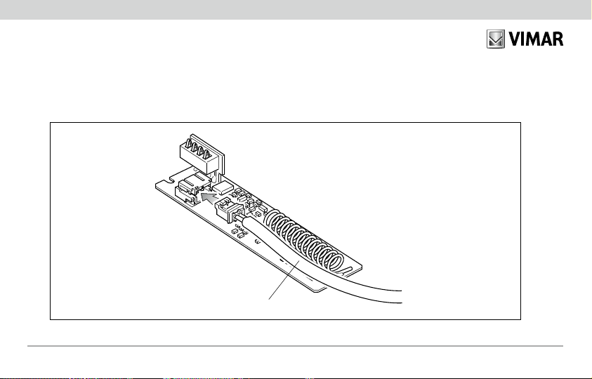
• Antenna utilizzabile:
- filo rigido di 17 cm (non fornito) da posizionare in verticale
Page 9

collegato al morsetto .
- antenna di 433 MHz con collegamento con cavo coassiale
(da utilizzarsi per portare a distanza l’antenna o dove si presentino problemi di ricezione).
Il filo rigido o l’antenna devono essere sempre montati.
• Contenitore: 6 moduli da 17,5 mm per guida EN 50022
• Grado di protezione: IP40
• Apparecchi di classe II:
• Numero di cicli automatici: 100.000
• Tipo di apertura dei contatti: microdisconnessione
• Tipo di azione: 1B
• Indice di tracking: PTI175
• Situazione di polluzione: normale
• Temperatura: 0 °C +55 °C
• Temperatura di spedizione e stoccaggio: -25 °C +60 °C
8. REGOLE DI INSTALLAZIONE.
• L’installazione deve essere effettuata secondo le norme CEI
vigenti.
• Prima di operare sull’impianto togliere la tensione di rete
agendo sull’interruttore generale.
• Utilizzare i conduttori isolati di colore giallo/verde solo per il
collegamento di terra.
• Verificare che la sezione dei conduttori di alimentazione sia
adeguata al carico alimentato ed in ogni caso non inferiore a 1,5
2
.
mm
• Serrare accuratamente i conduttori nei morsetti, in quanto
serraggi imperfetti possono provocare surriscaldamenti fino a
temperature sufficienti ad innescare un incendio.
9. CONFORMITÀ NORMATIVA.
Direttiva BT, EMC, R&TTE
Norme EN 60730-1, EN 60730-2-9, EN 300 220-3, EN 301 489-03.
5 - ITALIANO
Page 10

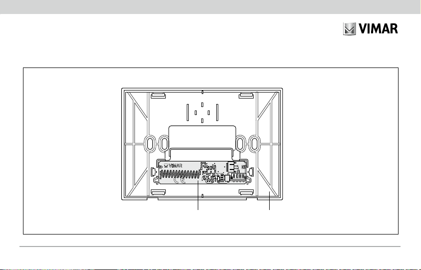
Comando a distanza mediante modulo trasmettitore in radiofrequenza.
01921.C
Per comandare l’accensione a distanza del cronotermostato o del termostato, utilizzare il cavo 01921.C dedicato al collegamento del modulo
trasmettitore in radiofrequenza al combinatore telefonico con attuatore.
6 - ITALIANO
Page 11
01911
01921
01921.1
Comando a distanza mediante modulo trasmettitore in radiofrequenza.
7 - ITALIANO
Page 12
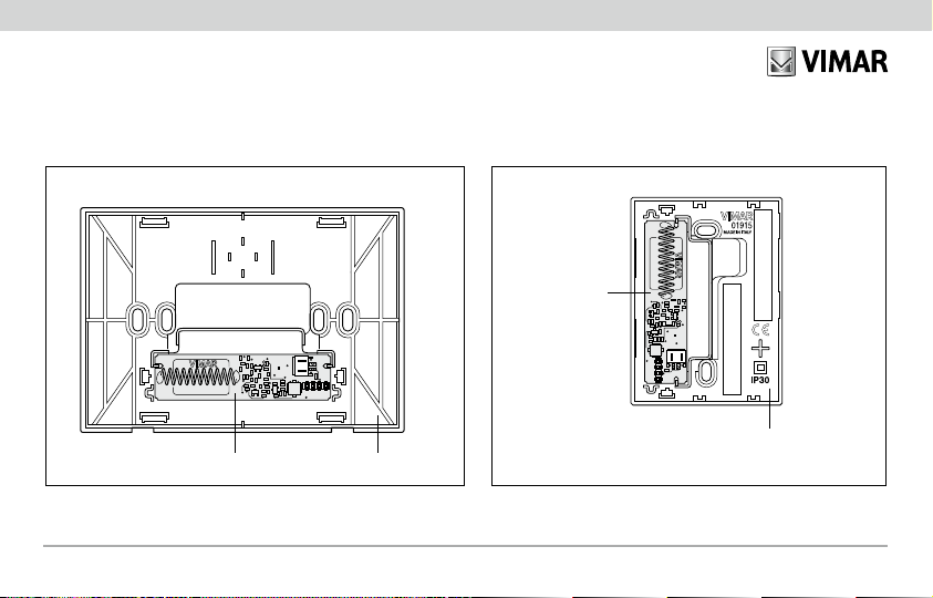
0191001921.1
01915
01921.1
Comando a distanza mediante modulo trasmettitore in radiofrequenza.
8 - ITALIANO
Page 13
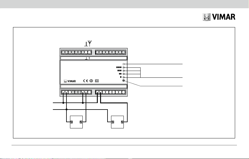
L
N
Collegamenti elettrici per comando
di pompe di circolazione, elettrovalvole, ecc.
funzionanti a 230 V~
Led alimentazione
Led canali di ricezione
e livello di ricezione
Antenna
U1 U2
01924
RX RADIO 4 CANALI
ON
P
SUPPLY:
230 V~
50-60 Hz
4 OUTPUTS:
1B
6(2) A 250 V~
C
NONC
C
NO
L
N NC
C
NONCCNONC
out 2out 1 out 3 out 4
ANTENNA
AERIAL
Tasto P programmazione
Esempio di collegamento.
9 - ITALIANO
Page 14

Page 15
CONTENTS.
1. Description. . . . . . . . . . . . . . . . . . . . . . . . . . . . . . . . . . . . . . . . . . . . . . . . . . . . . . . . . . . . . . . . . . . . . . . . . . . . . . . . . . . . . . . . . . . . 12
2. Operating mode. . . . . . . . . . . . . . . . . . . . . . . . . . . . . . . . . . . . . . . . . . . . . . . . . . . . . . . . . . . . . . . . . . . . . . . . . . . . . . . . . . . . . . . . 12
3. Configuration of 01910 programmable chronothermostats. . . . . . . . . . . . . . . . . . . . . . . . . . . . . . . . . . . . . . . . . . . . . . . . . . . . . . . . 12
4. Configuration of 01911 programmable chronothermostats. . . . . . . . . . . . . . . . . . . . . . . . . . . . . . . . . . . . . . . . . . . . . . . . . . . . . . . . 13
5. Configuration of 01915 thermostats. . . . . . . . . . . . . . . . . . . . . . . . . . . . . . . . . . . . . . . . . . . . . . . . . . . . . . . . . . . . . . . . . . . . . . . . . 13
6. Reset procedure . . . . . . . . . . . . . . . . . . . . . . . . . . . . . . . . . . . . . . . . . . . . . . . . . . . . . . . . . . . . . . . . . . . . . . . . . . . . . . . . . . . . . . . 14
7. Characteristics. . . . . . . . . . . . . . . . . . . . . . . . . . . . . . . . . . . . . . . . . . . . . . . . . . . . . . . . . . . . . . . . . . . . . . . . . . . . . . . . . . . . . . . . . 14
8. Installation rules . . . . . . . . . . . . . . . . . . . . . . . . . . . . . . . . . . . . . . . . . . . . . . . . . . . . . . . . . . . . . . . . . . . . . . . . . . . . . . . . . . . . . . . . 15
9. Conformity to standards. . . . . . . . . . . . . . . . . . . . . . . . . . . . . . . . . . . . . . . . . . . . . . . . . . . . . . . . . . . . . . . . . . . . . . . . . . . . . . . . . . 15
11 - ENGLISH
Page 16
1. DESCRIPTION.
Radiofrequency actuator-receiver, EN 50022 rail mount, occupies six
17.5-mm modules - RAL 7035 grey.
01923: 1 channel - 01924: 4 channels.
2. OPERATING MODE.
Illuminated green LED indicates that the power is on.
When an encoded signal is received from the 01915 thermostat or
from the 01910 and 01911 programmable thermostat, the corresponding channel is activated and the associated red LED lights up. If
no valid transmissions take place within 1 hour, the channel is closed
down for the safety of the system.
3. CONFIGURATION OF 01910 PROGRAMMABLE
CHRONOTHERMOSTATS.
• Replace the relay unit installed in the 01910 programmable chronothermostat with the 01921.1 radio-frequency transmitter unit (for the
replacement operation, refer to the instruction booklet of the programmable chronothermostat).
• Check that the symbol
display (wait max. 2 minutes for automatic detection).
12 - ENGLISH
appears on the programmable thermostat
• On the programmable thermostat, simultaneously press the
OK button and the button
channel CH 0x. Press the button
channel (from 1 to 4)
(select channel 1 for the 01923... receiver).
Press the OK button: this initiates the configuration transmis-
sion phase; it is signalled by a blinking cursor and antenna icon.
• The transmission continues for about 2 minutes, after which
normal operation is automatically resumed.
• During transmission, on receivers 01923 or 01924, press the
button P until the green LED starts to blink. Wait until the channel has been programmed, signalled by the blinking of the red
led associated with that channel.
• To display the reception level, press the button P; the level is
indicated by the number of red LEDs which light up:
- red LED 1: poor reception
- red LED 2: adequate reception
- red LED 3: good reception
- red LED 4: excellent reception
Press the button P a second time to exit programming mode.
; a screen appears displaying
, to select the desired
corresponding to the relay to be activated
green LED: off
}
Page 17
• To finish the procedure, press button C on the programmable
thermostat. In the case of the 01924 four channel actuator-receiver, repeat the procedure to configure the other channels.
4.CONFIGURATION OF
PROGRAMMABLE
CHRONOTHERMOSTATS 01911.
• Replace the relay module in the timer-thermostat 01911 with the
radio-frequency transmitter module 01921.1.
• On the timer-thermostat, go to the SETTINGS menu and select
CONFIG. RF; the screen will show CONFIG. RF. Using the rotary
knob, select the desired channel (from 1 to 4) corresponding
to the relay you want to control (if using receiver 01923 always
select channel 1). Press the
tion transmission phase commences.
• The transmission continues for 40 seconds, then the system
stops the procedure and goes back to the CONFIG RF menu
item. The transmission can be stopped manually by pressing the
selection button a second time.
• During the transmission, on the receiver 01923 or 01924 press
button P until the green LED blinks. Wait for channel programming to be signalled by the red LED corresponding to this
channel blinking.
selection button; the configura-
• To display the level of reception press button P until the green
LED goes out; the level is shown by the number of red LEDs
that light up:
- red LED 1: poor reception
- red LED 2: sufficient reception
- red LED 3: good reception
- red LED 4: optimum reception
Press button P until the green LED lights up again, to exit the
programming phase.
• If it has not yet ended automatically, stop the timer-thermostat
transmitting the configuration, press the
If using the 4-channel actuator 01924, repeat the procedure for
each of the channels you want to configure.
green LED: off
}
selection button.
5. CONFIGURATION OF 01915 THERMOSTATS.
• Replace the relay unit installed in the 01915 thermostat with the
01921.1 radio-frequency transmitter unit (for the replacement operation, refer to the instruction booklet of the thermostat).
• Check that the symbol
max. 2 minutes for automatic detection).
appears on the thermostat display (wait
13 - ENGLISH
Page 18
• Press the button
• Press the button
displaying channel CH 0x. to select the desired channel (from 1
to 4) corresponding to the relay to be activated (select channel 1
for the 01923... receiver). Press the OK button: this initiates the
transmission configuration phase; it is signalled by a blinking cursor
and antenna icon.
• The transmission continues for about 2 minutes, after which normal
operation is automatically resumed.
• During transmission, on the 01923 or 01924 receiver, press the
button P until the green LED starts to blink. Wait until the channel
has been programmed, indicated by the blinking of the red led associated with that channel.
• To display the reception level, press the button P; the level is indicated by the number of red LEDs which light up:
- red LED 1: poor reception
- red LED 2: adequate reception
- red LED 3: good reception
- red LED 4: excellent reception
Press the button P a second time to exit programming mode.
14 - ENGLISH
(summer/winter menu)
(radio configuration menu): a screen appears
green LED: off
}
• To finish the procedure, press the OK button on the thermo-
stat. In the case of the 01924 four channel actuator-receiver,
repeat the procedure to configure the other channels.
6. RESET PROCEDURE.
Press and hold down the button P for 5 seconds; this will clear
all the values stored in memory. The operation is signalled by
the simultaneous blinking of all the red LEDs and the green LED.
7. PRINCIPAL CHARACTERISTICS.
• Supply voltage: 230 V~ ±10% 50-60 Hz
• Power consumption: 2 VA
• Output:
- 01923: 1 relay 6(2) A 250 V with clean changeover contact
- 01924: 4 relays 6(2) A 250 V with clean changeover contact
• Receiver: ASK 433.92 MHz
• Sensitivity: -106 dBm approx.
• Usable antenna:
- 17 cm rigid wire antenna (not supplied) to be positioned vertically and connected to terminal
.
Page 19
- 433 MHz antenna with coaxial cable connection (to be used
when the antenna needs to be positioned at a distance, or
where there are reception problems).
The rigid wire or antenna must always be assembled.
• Enclosure: six 17.5-mm modules for EN 50022 rail mount
• Protection level: IP40
• Class II devices:
• Number of automatic cycles: 100.000
• Type of contact opening: micro-disconnect
• Type of action: 1B
• Tracking index: PTI175
• Pollution status: normal
• Temperature: 0 °C +55 °C
• Temperature for shipping and storage: -25 °C +60 °C
8. INSTALLATION RULES.
• The installation must be done according to in force Italian CEI
specifications (or equivalent rules for buildings electrical installation).
• Disconnect the mains acting on the main switch before operating on the system.
• Use the yellow/green insulated conductors only for the connection to the earthing circuit.
• Verify if the supply conductors cross-sectional area is sufficient
for the feeded load, in any case it must never be less than 1.5
2
.
mm
• Clamp fully, with care, the conductors in the terminals; faulty
clampings can cause temperature rises high enough for a fire
risk.
9. CONFORMITY TO STANDARDS.
BT, EMC, R&TTE Directives
EN 60730-1, EN 60730-2-9, EN 300 220-3, EN 301 489-03
Standards.
15 - ENGLISH
Page 20
Remote operation via radiofrequency transmitter unit.
01921.C
To switch on the programmable thermostat or thermostat from a remote location, use the cable 01921.C, which connects the radiofrequency
transmitter unit to the telephone dialler with actuator.
16 - ENGLISH
Page 21

Remote operation via radiofrequency transmitter unit.
01911
01921
01921.1
17 - ENGLISH
Page 22

0191001921.1
01915
01921.1
Remote operation via radiofrequency transmitter unit.
18 - ENGLISH
Page 23

L
N
Electrical connections for
controlling circulation pumps,
solenoid valves etc. operating at 230 V~.
Power indicator LED
Reception channel and
reception level LEDs
Antenna
U1 U2
01924
RX RADIO 4 CANALI
ON
P
SUPPLY:
230 V~
50-60 Hz
4 OUTPUTS:
1B
6(2) A 250 V~
C
NONC
C
NO
L
N NC
C
NONCCNONC
out 2out 1 out 3 out 4
ANTENNA
AERIAL
Programming button P
Connection example.
19 - ENGLISH
Page 24

Page 25

TABLES DES MATIERES.
1. Description . . . . . . . . . . . . . . . . . . . . . . . . . . . . . . . . . . . . . . . . . . . . . . . . . . . . . . . . . . . . . . . . . . . . . . . . . . . . . . . . . . . . . . . . . . . 22
2. Fonctionnement . . . . . . . . . . . . . . . . . . . . . . . . . . . . . . . . . . . . . . . . . . . . . . . . . . . . . . . . . . . . . . . . . . . . . . . . . . . . . . . . . . . . . . . 22
3. Configuration chronothermostats 01910 . . . . . . . . . . . . . . . . . . . . . . . . . . . . . . . . . . . . . . . . . . . . . . . . . . . . . . . . . . . . . . . . . . . . . 22
4. Configuration chronothermostats 01911 . . . . . . . . . . . . . . . . . . . . . . . . . . . . . . . . . . . . . . . . . . . . . . . . . . . . . . . . . . . . . . . . . . . . . 23
5. Configuration thermostats 01915 . . . . . . . . . . . . . . . . . . . . . . . . . . . . . . . . . . . . . . . . . . . . . . . . . . . . . . . . . . . . . . . . . . . . . . . . . . 23
6. Procedure de reset . . . . . . . . . . . . . . . . . . . . . . . . . . . . . . . . . . . . . . . . . . . . . . . . . . . . . . . . . . . . . . . . . . . . . . . . . . . . . . . . . . . . . 24
7. Caractéristiques techniques . . . . . . . . . . . . . . . . . . . . . . . . . . . . . . . . . . . . . . . . . . . . . . . . . . . . . . . . . . . . . . . . . . . . . . . . . . . . . . 24
8. Règles d’installation . . . . . . . . . . . . . . . . . . . . . . . . . . . . . . . . . . . . . . . . . . . . . . . . . . . . . . . . . . . . . . . . . . . . . . . . . . . . . . . . . . . . 25
9. Conformité aux Normes . . . . . . . . . . . . . . . . . . . . . . . . . . . . . . . . . . . . . . . . . . . . . . . . . . . . . . . . . . . . . . . . . . . . . . . . . . . . . . . . . 25
21 - FRANÇAIS
Page 26

1. DESCRIPTION.
Actuateur-récepteur en radiofréquence, installation sur guide EN
50022, occupe 6 modules de 17,5 mm - gris RAL 7035.
01923: 1 canal - 01924: 4 canaux
2. FONCTIONNEMENT.
La led verte allumée indique que l’alimentation est insérée.
En présence d’un signal codifié provenant du thermostat 01915 ou du
chronothermostat 01910 ou 01911, le canal correspondant s’active et
la led rouge correspondante s’allume. En l’absence de transmission
utile dans le délai d’1 heure, le canal se désactive pour la sécurité de
l’installation.
3. CONFIGURATION CHRONOTHERMOSTATS 01910.
• Remplacer le module relais installé dans le chronothermostat 01910
par le module émetteur en radiofréquence 01921.1 (pour les opérations de remplacement, se reporter au livret des instructions du
chronothermostat).
• Vérifier que sur l’écran du chronothermostat le symbole
(attendre max. 2 minutes pour la reconnaissance automatique).
22 - FRANÇAIS
soit affi
ché
• Sur le chronothermostat, presser en même temps la touche
OK et la touche
visualisée. Avec la touche
(de 1 à 4) correspondant au relais qu’il faut activer (sélectionner
le canal 1 pour le récepteur 01923...). Presser la touche OK
: la phase de transmission pour la configuration commence ;
l’icône de l’antenne et un curseur clignotent.
• La transmission continue pendant 2 minutes, puis le fonctionnement normal est rétabli automatiquement.
• Pendant la transmission, presser la touche P, sur le récepteur
01923 ou 01924 jusqu’à ce que la led verte clignote. Attendre
la programmation du canal signalée par le clignotement de la
led rouge du canal correspondant.
• Pour visualiser le niveau de réception, presser la touche P ; le
niveau est indiqué par le nombre de led rouges qui s’allument :
- led rouge 1: réception faible
- led rouge 2: réception suffisante
- led rouge 3: réception bonne
- led rouge 4: réception excellente
Presser la touche P une seconde fois pour quitter la phase de
programmation.
; la page-écran avec le canal CH 0x est
, sélectionner le canal souhaité
led verte : éteint
}
Page 27

• Pour terminer la procédure, presser la touche C sur le chro-
nothermostat. En cas d’actuateur-récepteur à quatre canaux
01924, répéter la procédure pour la configuration des autres
canaux.
4. CONFIGURATION CHRONOTHERMOSTATS 01911.
• Remplacer le module relais présent dans le chronothermostat
01911 avec le module émetteur en radiofréquence 01921.1.
• Sur le chronothermostat, accéder au menu PARAMETRE et
sélectionner l’option CONFIG. RF ; la page CONFIG. RF est
affichée. Au moyen de la manette rotative, sélectionner le canal
désiré (de 1 à 4) correspondant au relais que l’on veut commander (si l’on utilise le récepteur 01923, sélectionner toujours
canal 1). Appuyer sur la touche de sélection
transmission pour la configuration commence.
• La transmission continue pendant 40 secondes ; ensuite, le
système interrompt la procédure et retourne au poste du menu
CONFIG RF. La transmission peut être interrompue manuellement au moyen d’une seconde pression du bouton de sélection
.
• Durant la transmission, sur le récepteur 01923 ou 01924 appuyer sur la touche P jusqu’au clignotement de la led verte.
; la phase de
Attendre la programmation du canal qui est signalée par le cligno-
tement de la led rouge correspondant à ce canal.
• Pour visualiser le niveau de réception, appuyer sur la touche P
jusqu’à l’extinction de la led verte ; le niveau est indiqué par le
nombre de leds rouges qui s’allument :
- led rouge 1 : réception médiocre
- led rouge 2 : réception suffisante
- led rouge 3 : bonne réception
- led rouge 4 : excellente réception
Appuyer sur la touche P jusqu’au nouvel allumage de la led verte
pour quitter la phase de programmation.
• Si elle ne s’est pas encore terminée automatiquement, interrompre
la transmission de configuration de la part du chronothermostat,
appuyer sur le bouton de sélection
Si l’on utilise l’actionneur à 4 canaux 01924, répéter la procédure
pour chaque canal que l’on désire configurer.
led verte : éteint
}
.
5. CONFIGURATION THERMOSTATS 01915.
• Remplacer le module relais se trouvant dans le thermostat 01915
par le module émetteur en radiofréquence 01921.1 (pour les
opérations de remplacement, se reporter au livret d’instructions
du thermostat).
23 - FRANÇAIS
Page 28

• Vérifier la présence sur l’affichage du thermostat du symbole
(attendre max. 2 minutes pour la reconnaissance automatique)
• Presser la touche
• Presser la touche
indiquant le canal CH 0x s’affiche. A l’aide de la touche
lectionner le canal souhaité (de 1 à 4) correspondant au relais qui
doit être activé (sélectionner le canal 1 pour le récepteur 01923...).
Presser la touche OK : la phase de transmission pour la configura-
tion commence ; l’icône de l’antenne clignote.
• La transmission continue pendant 2 minutes environ, puis le fonctionnement normal est automatiquement rétabli.
• Pendant la transmission, sur le récepteur 01923 ou 01924 presser
la touche P jusqu’à ce que la led verte clignote. Attendre la programmation du canal signalé par le clignotement de la led rouge du
canal correspondant.
Pour visualiser le niveau de réception, presser la touche P ; le niveau
est indiqué par le nombre de led rouges qui s’allument :
- led rouge 1: réception faible
- led rouge 2: réception suffisante
- led rouge 3: réception bonne
- led rouge 4: réception excellente
24 - FRANÇAIS
(menu été/hiver)
(menu de configuration radio) : la page-écran
, sé-
led verte : éteint
}
Presser la touche P une seconde fois pour quitter la phase
de programmation.
• Pour terminer la procédure, presser la touche OK sur le ther-
mostat. En cas d’actuateur-récepteur à quatre canaux 01924,
répéter la procédure pour la configuration des autres canaux.
6. PROCEDURE DE RESET.
Garder la touche P pressée pendant 5 secondes ; toutes les mé-
morisations seront effacées. Le clignotement contemporain de
toutes les led rouges et de la led verte signale la présence de cette
phase.
7. CARACTERISTIQUES PRINCIPALES.
• Alimentation : 230 V~ ±10% 50-60 Hz
• Puissance absorbée : 2 VA
• Sortie :
- 01923: 1 relais 6(2) A 250 V~ avec contact inverseur vierge
- 01924: 4 relais 6(2) A 250 V~ avec contact inverseur vierge
• Récepteur : ASK 433.92 MHz
• Sensibilité : -106 dBm environ
• Antenne utilisable :
Page 29

- fil rigide de 17 cm (non fourni) à placer à la verticale, relié à la
.
borne
- antenne de 433 MHz avec raccordement avec câble coaxial
(à utiliser pour amener l’antenne à distance ou en cas de lieux
avec des problèmes de réception).
Le fil rigide ou l’antenne doivent toujours être montés.
• Conteneur : 6 modules de 17,5 mm par guide EN 50022
• Degré de protection : IP40
• Appareils de classe II:
• Nombre de cycles automatiques : 100.000
• Type d’ouverture des contacts : micro-déconnexion
• Type d’action : 1B
• Indicateur de cheminement : PTI175
• Situation relative à la pollution : normale
• Température : 0 °C +55 °C
• Température d’expédition et de stockage : -25 °C +60 °C
8. REGLES D’INSTALLATION.
• L’installation doit être effectuée selon les normes italiennes
CEI en vigueur (ou normes équivalentes pour les installations
électriques dans les bâtimentes).
• Couper l’alimentation en agissant sur l’interrupteur général avant
d’intervenir sur l’installation.
• Utiliser les câbles isolés de couleur jaune/verte seulement pour
la connexion au circuit de terre.
• Vérifier si la section des conducteurs d’alimentation est suffisante pour la charge alimentée, elle ne doit quand même jamais
être inférieure à 1,5 mm
• Serrer les conducteurs dans les bornes avec soin; un mauvais serrage
peut provoquer un échauffement excessif avec risque d’incendie.
2
.
9. CONFORMITE AUX NORMES.
Directive BT, EMC, R&TTE
Normes EN 60730-1, EN 60730-2-9, EN 300 220-3, EN 301 489-03.
25 - FRANÇAIS
Page 30

Commande à distance par module émetteur en radiofréquence.
01921.C
Pour commander l’allumage à distance du chronothermostat ou du thermostat, utiliser le câble 01921.C spécifiquement prévu pour la
connexion du module émetteur en radiofréquence au composeur téléphonique avec actuateur.
26 - FRANÇAIS
Page 31

Commande à distance par module émetteur en radiofréquence.
01911
01921
01921.1
27 - FRANÇAIS
Page 32

0191001921.1
01915
01921.1
Commande à distance par module émetteur en radiofréquence.
28 - FRANÇAIS
Page 33

L
N
Connexions électriques pour commande
de pompe de circulation, électrovanne,
etc. fonctionnant à 230 V~
Led alimentation
Led canaux de réception
et niveau de réception
Antenne
U1 U2
01924
RX RADIO 4 CANALI
ON
P
SUPPLY:
230 V~
50-60 Hz
4 OUTPUTS:
1B
6(2) A 250 V~
C
NONC
C
NO
L
N NC
C
NONCCNONC
out 2out 1 out 3 out 4
ANTENNA
AERIAL
Touche P programmation
Exemple de connexion.
29 - FRANÇAIS
Page 34

Page 35

INHALT.
1. Beschreibung . . . . . . . . . . . . . . . . . . . . . . . . . . . . . . . . . . . . . . . . . . . . . . . . . . . . . . . . . . . . . . . . . . . . . . . . . . . . . . . . . . . . . . . . . 32
2. Funktion . . . . . . . . . . . . . . . . . . . . . . . . . . . . . . . . . . . . . . . . . . . . . . . . . . . . . . . . . . . . . . . . . . . . . . . . . . . . . . . . . . . . . . . . . . . . . 32
3. Konfiguration der chronothermostate der baureihe 01910 . . . . . . . . . . . . . . . . . . . . . . . . . . . . . . . . . . . . . . . . . . . . . . . . . . . . . . . . 32
4. Konfiguration der chronothermostate der baureihe 01911 . . . . . . . . . . . . . . . . . . . . . . . . . . . . . . . . . . . . . . . . . . . . . . . . . . . . . . . . 33
5. Konfiguration der thermostate der baureihe 01915 . . . . . . . . . . . . . . . . . . . . . . . . . . . . . . . . . . . . . . . . . . . . . . . . . . . . . . . . . . . . . 33
6. Rücksetzung (reset) . . . . . . . . . . . . . . . . . . . . . . . . . . . . . . . . . . . . . . . . . . . . . . . . . . . . . . . . . . . . . . . . . . . . . . . . . . . . . . . . . . . . . 34
7. Wichtigste kenndaten . . . . . . . . . . . . . . . . . . . . . . . . . . . . . . . . . . . . . . . . . . . . . . . . . . . . . . . . . . . . . . . . . . . . . . . . . . . . . . . . . . . 35
8. Anweisungen für die Installation . . . . . . . . . . . . . . . . . . . . . . . . . . . . . . . . . . . . . . . . . . . . . . . . . . . . . . . . . . . . . . . . . . . . . . . . . . . 35
9. Entsprechung zu den Normen . . . . . . . . . . . . . . . . . . . . . . . . . . . . . . . . . . . . . . . . . . . . . . . . . . . . . . . . . . . . . . . . . . . . . . . . . . . . . 35
31 - DEUTSCH
Page 36

1. BESCHREIBUNG.
Funkfrequenz-Zuschalter/Empfänger, installiert auf Schiene nach EN
50022, Platzbedarf 6 Module zu 17,5 mm - Farbe grau RAL 7035.
01923: 1 Kanal - 01924: 4 Kanäle
2. FUNKTION.
Das grüne Led leuchtet auf, sobald die Spannungsversorgung zugeschaltet ist. Bei Präsenz eines kodifizierten Signals, das von einem
Thermostat Mod. 01915 oder einem Chronothermostat Mod. 01910
oder 01911 ausgeht, wird der entsprechende Kanal aktiviert, und das
entsprechende rote Led leuchtet auf. Wenn innerhalb 1 Std. keine Signale übertragen werden, schaltet sich der Kanal ab, so daß ein maximaler Schutz der Anlage gewährleistet ist.
3. KONFIGURATION DER CHRONOTHERMOSTATE
DER BAUREIHE 01910.
• Tauschen Sie das im Chronothermostat 01910 präsente Relaismodul gegen ein Funkfrequenz-Sendemodul Mod. 01921.1 aus Beziehen Sie sich hinsichtlich der Anleitungen zum Austausch auf die zum
Chronothermostat gehörende Betriebsanleitung).
• Vergewissern Sie sich, daß auf dem Display des Chronothermostats
das Symbol
tische Signalerfassung ab).
32 - DEUTSCH
erscheint (warten Sie max. 2 Minuten die automa-
• Drücken Sie gleichzeitig die auf dem Chronothermostat instal-
lierte Taste OK und die Taste
Bildschirmseite zum Kanal CH 0x. Wählen Sie mit der Taste
, den Kanal (von 1 bis 4), der dem zu aktivierenden Relais entspricht (wählen Sie beim Empfangsteil Mod. 01923... den Kanal 1).
Drücken Sie anschließend die Taste OK. Nun beginnt die Phase
der Übertragung der Parameter zur Konfiguration des Geräts; das
Antennensymbol und ein Cursor blinken auf.
• Die Übertragung der Konfigurationsparameter dauert etwa 2
Minuten, anschließend stellt sich das Gerät selbsttätig auf die
normale Betriebsart ein.
• Während der Übertragung müssen Sie auf dem Empfangsteil
Mod. 01923 bzw. 01924 so lange die Taste P drücken, bis das
grüne Led aufblinkt. Warten Sie den Abschluß der Programmierung des Kanals ab, der durch Aufblinken des roten Leds
des entsprechenden Kanals gemeldet wird.
Drücken Sie zur Abbildung des Empfangspegels die Taste
P; der Empfangspegel wird durch die jeweils aufleuchtenden
roten Leds angezeigt:
- rotes Led 1: schlechter Empfang
- rotes Led 2: Empfang ausreichend
- rotes Led 3: guter Empfang
- rotes Led 4: optimaler Empfang
; auf dem Display erscheint die
grünes Led:
Gerät ausgeschaltet
}
Page 37

Drücken Sie anschließend erneut die Taste P, um die Phase der
Programmierung zu verlassen.
• Drücken Sie zur Beendigung des Vorgangs die Taste C des Chrono-
thermostats. Bei Zuschalter/Empfänger mit 4 Kanälen, Mod. 01924,
muß der o.a. Vorgang zur Konfiguration der weiteren Kanäle wiederholt werden.
4. KONFIGURATION
CHRONOTHERMOSTATE DER
BAUREIHE 01911.
• Das Relaismodul im Uhrenthermostat 01911 durch das
Funksendermodul 01921.1 ersetzen.
• Am Uhrenthermostat das Menü EINSTELL. öffnen und die Option
KONFIG. RF wählen; daraufhin erscheint die Bildschirmanzeige
KONFIG. RF. Mit dem Drehknopf den gewünschten Kanal
wählen (von 1 bis 4), der dem Relais entspricht, das angesteuert
werden soll (bei Verwendung des Empfängers 01923 immer
Kanal 1 wählen). Die Wahltaste
für die Konfiguration beginnt.
• Die Übertragung dauert 40 Sekunden, danach unterbricht das
System die Prozedur und kehrt zum Menüpunkt KONFIG. RF
zurück. Durch erneutes Drücken der Wahltaste
Übertragung von Hand unterbrochen werden.
• Während der Übertragung am Empfänger 01923 bzw. 01924
drücken; die Übertragung
kann die
die Taste P drücken, bis die grüne Led blinkt. Die Programmierung
des Kanals abwarten, die durch das Blinken der diesem Kanal
entsprechenden roten Led angezeigt wird.
• Zur Anzeige des Empfangspegels die Taste P drücken, bis
die grüne Led erlischt; der Pegel ist anhand der Anzahl der
aufleuchtenden roten Leds abzulesen:
- rote Led 1: schlechter Empfang
rote Led 2: ausreichender Empfang grüne
-
- rote Led 3: guter Empfang
- rote Led 4: ausgezeichneter Empfang
Um die Programmierungsphase zu verlassen, die Taste P drü-
cken, bis die grüne Led wieder aufleuchtet.
• Falls sie noch nicht automatisch beendet wurde, die
Konfigurationsübertragung durch den Uhrenthermostat unterbrechen, die Wahltaste
Bei Verwendung des 4-Kanal-Aktors 01924 muss die Prozedur
für jeden Kanal, der konfiguriert werden soll, wiederholt werden.
drücken.
grünes Led:
Gerät ausgeschaltet
}
5. KONFIGURATION DER THERMOSTATE DER
BAUREIHE 01915.
• Tauschen Sie das im Thermostat 01915 präsente Relaismodul gegen
ein Funkfrequenz-Sendemodul 01921.1 aus (Bezie hen Sie sich
33 - DEUTSCH
Page 38

hinsichtlich der Anleitungen zum Austausch auf die zum Thermostat
gehörende Betriebsanleitung).
• Vergewissern Sie sich, daß auf dem Display des Thermostats das
Symbol
erscheint (warten Sie max. 2 Minuten die automatische
Signalerfassung ab).
• Drücken Sie die Taste
• Drücken Sie die Taste
gung): auf dem Display erscheint die Bildschirmseite zum Kanal CH
0x. Wählen Sie mit der Taste
zu aktivierenden Relais entspricht (wählen Sie beim Empfangsteil
Mod. 01923... den Kanal 1). Drücken Sie anschließend die Taste
OK. Nun beginnt die Phase der Übertragung der Parameter zur
Konfiguration des Geräts; das Antennensymbol blinkt auf.
• Die Übertragung der Konfigurationsparameter dauert etwa 2 Minuten, anschließend stellt sich das Gerät selbsttätig auf die normale
Betriebsart ein.
• Während der Übertragung müssen Sie auf dem Empfangsteil Mod.
01923 bzw. 01924 so lange die Taste P drücken, bis das grüne Led aufblinkt. Warten Sie den Abschluß der Programmierung
des Kanals ab, der durch Aufblinken des roten Leds des entsprechenden Kanals gemeldet wird.
34 - DEUTSCH
(Menü Sommer/ Winter)
(Menü zur Konfiguration der Funkübertra-
, den Kanal (von 1 bis 4), der dem
• Drücken Sie zur Abbildung des Empfangspegels die Taste P;
der Empfangspegel wird durch jeweils aufleuchtenden roten
Leds angezeigt:
- rotes Led 1: schlechter Empfang
- rotes Led 2: Empfang ausreichend
- rotes Led 3: guter Empfang
- rotes Led 4: optimaler Empfang
Drücken Sie anschließend erneut die Taste P, um die Phase
der Programmierung zu verlassen.
• Drücken Sie zur Beendigung des Vorgangs die Taste OK des
Thermostats. Bei Zuschalter/Empfänger mit 4 Kanälen, Mod.
01924, muß der o.a. Vorgang zur Konfiguration der weiteren
Kanäle wiederholt werden.
grünes Led:
Gerät ausgeschaltet
}
6. RÜCKSETZUNG (RESET).
Halten Sie die Taste P 5 Sekunden lang gedrückt, um alle Parameter aus dem Programmspeicher zu löschen. Die Löschung
wird durch gleichzeitiges Aufblinken aller roten Leds und des
grünen Leds bestätigt.
Page 39

7. WICHTIGSTE KENNDATEN.
• Versorgungsspannung: 230 V~ ±10% 50-60 Hz
• Aufnahmeleistung: 2 VA
• Ausgänge:
- 01923: 1 Relaisausgang 6(2) A 250 V~ mit blankem Umschaltkontakt
- 01924: 4 Relaisausgänge 6(2) A 250 V~ mit blankem Umschaltkontakt
• Empfangsteil: ASK 433.92 MHz
• Empfindlichkeit: ca. -106 dBm
• anschließbare Antennen:
- Steifdrahtantenne 17 cm (nicht mitgeliefert), für vertikale Ausrichtung, Anschluß an Klemme
- 433 MHz-Antenne mit Koaxialkabel (für vom Gerät entfernte
Installationsart oder bei Empfangsproblemen einzusetzen).
Das Gerät muß in jedem Fall an eine Steifdrahtantenne
oder eine normale Antenne angeschlossen sein!
• Gehäuse: 6 Module 17,5 mm, zur Installation auf Schiene EN 50022
• Schutzart: IP40
• Geräteklasse II:
• Anzahl der automatischen Zyklen: 100.000
• Art der Kontaktöffnung: Mikrotrennung
• Schaltart: 1B
• Tracking-Index: PTI175
• Umweltbelastung: normal
.
• Temperaturbereich: 0 °C +55 °C
• Temperaturbereich für Versand und Lagerung: -25 °C +60 °C
8. ANWEISUNGEN FÜR DIE INSTALLATION.
• Die Installation muss gemäß den geltenden EG-Normen erfolgen.
• Vor Hantieren mit der Anlage die Netzspannung durch
Betätigung des Hauptschalters ausschalten.
• Die gelb/grünen isolierten Leitungen nur für die Erdverbindung
benutzen.
• Sicherstellen, dass der Durchmesser der Zufuhrkabel der
Netzlast entspricht und in jedem Fall nicht unter 1,5 mm
• Die Leitungen sorgfältig abklemmen, da ungenaue Fixierungen zu
einer Überhitzung führen können, die Brandgefahr zur Folge hat.
2
liegt.
9. ENTSPRECHUNG ZU DEN NORMEN.
Richtlinie BT, EMC, R&TTE
Normen EN 60730-1, EN 60730-2-9, EN 300 220-3, EN 301 489-03.
35 - DEUTSCH
Page 40

Fernsteuerung über Funkfrequenz-Sendemodul.
01921.C
Zur Fernwirksteuerung der Einschaltung des Chronothermostats bzw. Thermostats müssen Sie mit dem Kabel 01921.C das Funkfrequenz-Sendemodul an eine Telefon-Wähltastatur mit Schaltglied anschließen.
36 - DEUTSCH
Page 41

Fernsteuerung über Funkfrequenz-Sendemodul.
01911
01921
01921.1
37 - DEUTSCH
Page 42

0191001921.1
01915
01921.1
Fernsteuerung über Funkfrequenz-Sendemodul.
38 - DEUTSCH
Page 43

L
N
Anschluß zur Steuerung
von Umlaufpumpen, Magnetventilen, etc.
mit Betriebsspannung 230 V~
Led Spannungsversorgung
Leds Empfangskanäle
und Empfangspegel
Antenne
U1 U2
01924
RX RADIO 4 CANALI
ON
P
SUPPLY:
230 V~
50-60 Hz
4 OUTPUTS:
1B
6(2) A 250 V~
C
NONC
C
NO
L
N NC
C
NONCCNONC
out 2out 1 out 3 out 4
ANTENNA
AERIAL
Taste P (Programmierung)
Anschlußbeispiel.
39 - DEUTSCH
Page 44

Page 45

ÍNDICE.
1. Descripción . . . . . . . . . . . . . . . . . . . . . . . . . . . . . . . . . . . . . . . . . . . . . . . . . . . . . . . . . . . . . . . . . . . . . . . . . . . . . . . . . . . . . . . . . . . 42
2. Funcionamiento . . . . . . . . . . . . . . . . . . . . . . . . . . . . . . . . . . . . . . . . . . . . . . . . . . . . . . . . . . . . . . . . . . . . . . . . . . . . . . . . . . . . . . . 42
3. Configuración de los cronotermostatos 01910 . . . . . . . . . . . . . . . . . . . . . . . . . . . . . . . . . . . . . . . . . . . . . . . . . . . . . . . . . . . . . . . . 42
4. Configuración de los cronotermostatos 01911 . . . . . . . . . . . . . . . . . . . . . . . . . . . . . . . . . . . . . . . . . . . . . . . . . . . . . . . . . . . . . . . . 43
6. Configuración de los termostatos 01915 . . . . . . . . . . . . . . . . . . . . . . . . . . . . . . . . . . . . . . . . . . . . . . . . . . . . . . . . . . . . . . . . . . . . . 43
7. Procedimiento de puesta a cero . . . . . . . . . . . . . . . . . . . . . . . . . . . . . . . . . . . . . . . . . . . . . . . . . . . . . . . . . . . . . . . . . . . . . . . . . . . 44
8. Características principales . . . . . . . . . . . . . . . . . . . . . . . . . . . . . . . . . . . . . . . . . . . . . . . . . . . . . . . . . . . . . . . . . . . . . . . . . . . . . . . . 44
9. Reglas de instalación . . . . . . . . . . . . . . . . . . . . . . . . . . . . . . . . . . . . . . . . . . . . . . . . . . . . . . . . . . . . . . . . . . . . . . . . . . . . . . . . . . . 45
10. Conformidad con la normativa . . . . . . . . . . . . . . . . . . . . . . . . . . . . . . . . . . . . . . . . . . . . . . . . . . . . . . . . . . . . . . . . . . . . . . . . . . . . 45
41 - ESPAÑOL
Page 46

1. DESCRIPCIÓN.
Actuador-receptor por radiofrecuencia. Instalación, con guía EN
50022. Ocupa 6 módulos de 17,5 mm - gris RAL 7035.
01923: 1 canal - 01924: 4 canales.
2. FUNCIONAMIENTO.
El led verde encendido indica que la alimentación está conectada. Ante
una señal codificada, procedente del termostato 01915 o del cronotermostato 01910 o 01911 el canal correspondiente se acciona y se enciende el relativo led rojo. Si, al cabo de 1 hora, no tiene lugar ninguna
transmisión útil, el canal se desactiva, para preservar la seguridad de las
instalaciones.
3.C ON FIG UR ACI ÓN DE L OS
CRONOTERMOSTATOS 01910.
• Cambie el módulo del relé del cronotermostato 01910 por el módulo
transmisor por radiofrecuencia 01921.1 (para más información acerca de las operaciones de cambio, véase el Manual de Instrucciones
del Cronotermostato).
• Verifique si en el display del cronotermostato se encuentra visualizado el símbolo
lugar el reconocimiento automático).
42 - ESPAÑOL
(aguarde 2 minutos, como máximo, para que tenga
• En el cronotermostato, pulse al mismo tiempo el botón OK
y el botón
Mediante el botón
que ha de ser el correspondiente al relé a activar (seleccione el
canal 1 para el receptor 01923...). Pulse el botón OK: principia
la fase de transmisión para realizar la configuración. El icono
de la antena y un cursor parpadean.
• La transmisión prosigue durante 2 minutos aproximadamente.
Acto seguido, el funcionamiento normal se restaura automáticamente.
• Durante la transmisión, en el receptor 01923 o 01924, mantenga enclavado el botón P hasta que el led verde comience
a parpadear. Aguarde hasta que comience a parpadear el led
rojo del canal correspondiente, indicando que la programación
del canal se está realizando.
• Para visualizar el nivel de recepción, pulse el botón P. El nivel
lo indica el número de leds rojos que se encienden:
- led rojo 1: recepción deficitaria
- led rojo 2: recepción suficiente
- led rojo 3: recepción buena
- led rojo 4: recepción excelente
Pulse el botón P una vez más para salir de la fase de programación.
•
; se visualiza el pantallazo con el canal CH 0x.
, seleccione el canal deseado (de 1 a 4),
led verde: apagado
}
Page 47

• Para terminar el procedimiento, pulse el botón C en el crono ter-
mostato. Si su actuador-receptor posee cuatro canales 01924,
repita el procedimiento susodicho, a efectos de configurar los
demás canales.
4.C ON FIG UR ACI ÓN DE LOS
CRONOTERMOSTATOS 01911.
• Sustituir el módulo relé del cronotermostato 01911 con el módulo transmisor en radiofrecuencia 01921.1.
• En el cronotermostato, acceder al menú PARAMETR. y seleccionar la opción CANAL RF; se visualiza la ventana CANAL RF.
Mediante el mando rotativo, seleccionar el canal (de 1 a 4) que
corresponde al relé que se desea mandar (si se utiliza el receptor
01923, hay que seleccionar siempre el canal 1). Presionar el
pulsador de selección
configuración.
• La transmisión continúa durante 40 segundos y, luego, el sistema la interrumpe y regresa a CANAL RF. La transmisión puede
interrumpirse manualmente presionando de nuevo el pulsador
de selección
• Durante la transmisión, en el receptor 01923 o 01924, pulsar la
tecla P hasta que el led verde parpadee. Esperar a que la
; inicia la fase de transmisión para la
.
programación del canal haya terminado (el led rojo, correspondien-
te a dicho canal, parpadea).
• Para visualizar el nivel de recepción, pulsar la tecla P hasta que el
led verde se apague; el nivel se indica mediante el número de leds
rojos que se encienden:
- led rojo 1: recepción escasa
- led rojo 2: recepción suficiente
- led rojo 3: recepción buena
- led rojo 4: recepción óptima
Para salir de la fase de programación, pulsar la tecla P hasta que
el led verde se vuelve a encender.
• Si la transmisión de la configuración del cronotermostato no
termina automáticamente, es posible interrumpirla presionando el
pulsador de selección
Si se utiliza el actuador de 4 canales 01924, repetir el procedimien-
to para cada uno de los canales que se desea configurar.
led verde: apagado
}
.
5. CONFIGURACIÓN DE LOS TERMOSTATOS
01915.
• Cambie el módulo del relé del termostato 01915 por el módulo
transmisor por radiofrecuencia 01921.1 (para más información
acerca de las operaciones de cambio, consulte el Manual.
43 - ESPAÑOL
Page 48

• Verifique que en el display del termostato se halle visualizado el
• Pulse el botón
• Pulse el botón
• La transmisión prosigue durante 2 minutos aproximadamente. Acto se-
• Durante la transmisión, en el receptor 01923 o 01924, mantenga
• Para visualizar el nivel de recepción, pulse el botón P. El nivel lo
- led rojo 1: recepción deficitaria
- led rojo 2: recepción suficiente
- led rojo 3: recepción buena
- led rojo 4: recepción excelente
44 - ESPAÑOL
(aguarde 2 minutos, como máximo, para que tenga
símbolo
lugar el reconocimiento automático).
pantallazo con el canal CH 0x. Con el botón
nal deseado (de 1 a 4) correspondiente al relé a activar (seleccione
el canal 1 para el receptor 01923...). Pulse el botón OK: principia
la fase de transmisión para la configuración. El icono de la antena
parpadea.
guido, se restaura automáticamente el funcionamiento normal.
enclavado el botón P hasta que el led verde comience a parpadear. Aguarde hasta que comience a parpadear el led rojo del ca
correspondiente, indicando que la programación del canal se está realizando.
indica el número de leds rojos que se encienden:
(menú verano/invierno).
(menú de configuración radio): se visualiza el
led verde: apagado
}
, seleccione el ca-
nal
Pulse el botón P una vez más, para salir de la fase de programación.
• Para concluir el procedimiento, pulse el botón OK del termos-
tato. Si su actuador-receptor posee cuatro canales 01924, repita el procedimiento anterior, para configurar los demás canales.
6. PROCEDIMIENTO DE PUESTA A CERO.
Mantenga enclavado el botón P durante 5 segundos. De esta
manera, se borrará toda la información que está guardada en
la memoria del artefacto. Indica esta fase el parpadeo de todos
los leds rojos y del led verde al mismo tiempo.
7. CARACTERÍSTICAS PRINCIPALES.
• Alimentación: 230 V~ ±10% 50-60 Hz
• Potencia absorbida: 2 VA
• Salidas:
- 01923: 1 relé 6(2) A 250 V~ con contacto libre en intercambio
- 01924: 4 relés 6(2) A 250 V~ con contacto libre en intercambio
• Receptor: ASK 433.92 MHz
• Sensibilidad: -106 dBm aproximadamente
• Antena que se puede utilizar:
- hilo rígido de 17 cm (se compra por separado). Se posiciona
Page 49

rá en sentido vertical y se conectará con el borne
- Antena de 433 MHz, con conexión mediante cable coaxial
(que se empleará para transportar la antena a larga distancia;
o bien, cuando surjan problemas de recepción defectuosa).
El hilo rígido o la antena siempre tienen que estar montados.
• Caja: 6 módulos de 17,5 mm para guía EN 50022
• Grado de protección: IP40
• Artefactos de clase II:
• Número de ciclos automáticos: 100.000
• Tipo de apertura de los contactos: microdesconexión
• Tipo de acción: 1B
• Índice de rastreo o tracking: PTI175
• Tipo de polución: normal
• Temperatura: 0 °C +55 °C
• Temperatura de transporte y almacenaje: -25 °C +60 °C
.
8. REGLAS DE INSTALACIÓN.
• La instalación tiene que ser realizada en confomidad a las
normas italianas CEI vigentes (o normas equivalentes para las
instalaciones eléctricas en los edificios).
• Antes de realizar cualquier conexión, cortar la alimentación de
corriente mediante el interruptor general.
• Utilizar cables aislados de color amarillo/verde sólo para las
conexiones de tierra.
• Verificar que la sección de los conductores de alimentación sea
adecuada para la carga y en ningún caso sea menor de 1,5 mm
• Sujetar correctamente los cables a los terminales; una sujeción
imperfecta puede provocar recalentamientos que podrían causar incendios.
2
9. CONFORMIDAD A LAS NORMAS.
Directiva BT, EMC y R&TTE
Normas EN 60730-1, EN 60730-2-9, EN 300 220-3, EN 301 489-03.
45 - ESPAÑOL
Page 50

Mando de control remoto con módulo transmisor por radiofrecuencia.
01921.C
Para gobernar el encendido a distancia del cronotermostato o del termostato, utilice el cable 01921.C, específico para conectar el módulo
transmisor por radiofrecuencia con el marcador telefónico automático con actuador.
46 - ESPAÑOL
Page 51

Mando de control remoto con módulo transmisor por radiofrecuencia.
01911
01921
01921.1
47 - ESPAÑOL
Page 52

0191001921.1
01915
01921.1
Mando de control remoto con módulo transmisor por radiofrecuencia.
48 - ESPAÑOL
Page 53

L
N
Conexiones eléctricas, para gobernar
las bombas de circulación y las electroválvulas,
etc., que funcionan a 230 V~
Led de alimentación
Leds de los canales de recepción
y nivel de recepción.
Antena
U1 U2
01924
RX RADIO 4 CANALI
ON
P
SUPPLY:
230 V~
50-60 Hz
4 OUTPUTS:
1B
6(2) A 250 V~
C
NONC
C
NO
L
N NC
C
NONCCNONC
out 2out 1 out 3 out 4
ANTENNA
AERIAL
Botón P de programación
Ejemplo de conexión.
49 - ESPAÑOL
Page 54

Page 55

ΠΕΡΙΕΧΟΜΕΝΑ.
1. Περιγραφή. . . . . . . . . . . . . . . . . . . . . . . . . . . . . . . . . . . . . . . . . . . . . . . . . . . . . . . . . . . . . . . . . . . . . . . . . . . . . . . . . . . . . . . . . . . . 52
2. Λειτουργία. . . . . . . . . . . . . . . . . . . . . . . . . . . . . . . . . . . . . . . . . . . . . . . . . . . . . . . . . . . . . . . . . . . . . . . . . . . . . . . . . . . . . . . . . . . . 52
3. Ρυθμισεις θερμοστατων 01910. . . . . . . . . . . . . . . . . . . . . . . . . . . . . . . . . . . . . . . . . . . . . . . . . . . . . . . . . . . . . . . . . . . . . . . . . . . . 52
4. Ρυθμισεις θερμοστατων 01911 . . . . . . . . . . . . . . . . . . . . . . . . . . . . . . . . . . . . . . . . . . . . . . . . . . . . . . . . . . . . . . . . . . . . . . . . . . . . 53
5. Ρυθμισεις θερμοστατων 01915. . . . . . . . . . . . . . . . . . . . . . . . . . . . . . . . . . . . . . . . . . . . . . . . . . . . . . . . . . . . . . . . . . . . . . . . . . . . 53
6. Διαδικασια reset . . . . . . . . . . . . . . . . . . . . . . . . . . . . . . . . . . . . . . . . . . . . . . . . . . . . . . . . . . . . . . . . . . . . . . . . . . . . . . . . . . . . . . . 54
7. Κυρια χαρακτηριστικα . . . . . . . . . . . . . . . . . . . . . . . . . . . . . . . . . . . . . . . . . . . . . . . . . . . . . . . . . . . . . . . . . . . . . . . . . . . . . . . . . . . 54
8. Κανονες εγκαταστασης . . . . . . . . . . . . . . . . . . . . . . . . . . . . . . . . . . . . . . . . . . . . . . . . . . . . . . . . . . . . . . . . . . . . . . . . . . . . . . . . . . 55
9. Προδιαγραφες. . . . . . . . . . . . . . . . . . . . . . . . . . . . . . . . . . . . . . . . . . . . . . . . . . . . . . . . . . . . . . . . . . . . . . . . . . . . . . . . . . . . . . . . . 55
51 - ΕΛΛΗΝΙΚΑ
Page 56

1.
ΠΕΡΙΓΡΑΦΗ.
Εκκινητής-δέκτης ραδιοσυχνοτήτων, εγκατάσταση σε ράγα ΕΝ
50022, καταλαμβάνει 6 modules 17,5 mm - γκρί RAL 7035.
01923:1 κανάλι- 01924:4 κανάλια.
2.
ΛΕΙΤΟΥΡΓΙΑ.
Το αναμμένο πράσινο led δεικνύει παρουσία τάσεως. Στην
παρουσία ενός κωδικοποιημένου σήματος προερχόμενου απο τον
θερμοστάτη 01915 ή απο τον χρονοθερμοοτάτη 01910 - 01911, το
αντίστοιχο κανάλι ενεργοποιείται και ανάβει το αντίστοιχο κόκκινο
led. Εάν δεν υπάρχουν χρήσιμες μεταδόσεις μέσα σε 1 ώρα το
κανάλι απενεργοποιείται για την ασφάλεια της εγκατάστασης.
3.
ΡΥΘΜΙΣΕΙΣ ΘΕΡΜΟΣΤΑΤΩΝ 01910.
• Αντικατα στήστε το module ρελέ που υπάρ χει στο
χρονοθερμοστάτη 01910 με το module πομπό συχνοτήτων
01921.1 (για τις εργασίες αντικατάστασης συμβουλευθείτε το
φυλλάδιο οδηγιών του χρονοθερμοστάτη).
• Επιβεβαιώστε ότι στην οθόνη του χρονοθερμοστάτη εμφανίζεται
το σύμβολο
αναγνώριση).
• Στο χρονοθερμοστάτη, πίεστε ταυτόχρονα το πλήκτρο ΟΚ και
το πλήκτρο
52 - ΕΛΛΗΝΙΚΑ
(αναμείνατε max. 2 λεπτά για την αυτόματη
- εμφανίζεται η εικόνα με το κανάλι CΗ Οx.
Με το πλήκτρο
έως 4) αντίστοιχο στο ρελέ που πρέπει να ενεργοποιηθεί
(επιλέξτε κανάλι 1 για το δέκτη 01923...). Πιέστε το
πλήκτρο ΟΚ: ξεκινά η φάση μετάδοσης για τη ρύθμιση. Η
εικόνα της κεραίας και του κέρσορα αναβοσβήνει.
• Η μετάδοση συνεχίζεται για περίπου 2 λεπτά επανερχόμενο
μετά αυτομάτως στην κανονική λειτουργία.
• Κατά την διάρκεια της μετάδοσης, στο δέκτη 01923 ή
01924 πιέστε το πλήκτρο Ρ μέχρις ότου το πράσινο
led αναβοσβήνει. Αναμείνατε τον προγραμματισμό του
καναλιού που δεικνύεται απο το αναβόσβησμα του
κόκκινου led του αντίστοιχου καναλιού.
• Για να δείτε το επίπεδο λήψης, πιέστε το πλήκτρο Ρ, το
επίπεδο δεικνύεται από τον αριθμό των κόκκινων led που
αναβοσβήνουν:
- led κόκκινο 1: λήψη ανεπαρκής
- led κόκκινο 2: λήψη ικανοποιητική
- led κόκκινο 3: λήψη καλή
- led κόκκινο 4: λήψη εξαιρετική
• Πιέστε το πλήκτρο Ρ μια δεύτερη φορά για να εξέλθετε
από τον προγραμματισμό.
• Για τερματισμό της διαδικασίας, πιέστε το πλήκτρο C του
χρονοθερμοστάτη. Στην περίπτωση του εκκινητή-δέκτη
, επιλέξτε το επιθυμητό κανάλι (απο 1
led πράσινο: σβηστό
}
Page 57

4 καναλών 01924, επαναλάβατε την διαδικασία για την
ρύθμιση των άλλων καναλιών.
4. ΡΥΘΜΙΣΕΙΣ ΘΕΡΜΟΣΤΑΤΩΝ 01911.
• Αντικαταστήστε τη μονάδα ρελέ που υπάρχει στο χρονοθερμοστάτη
01911 με τη μονάδα πομπού με ραδιοσυχνότητα 01921.1.
• Στο χρονοθερμοστάτη ανοίξτε το μενού SETTINGS και επιλέξτε
CONFIG. RF, εμφανίζεται η οθόνη CONFIG. RF. Με τον
περιστροφικό διακόπτη επιλέξτε το επιθυμητό κανάλι (από 1 έως 4)
που αντιστοιχεί στο ρελέ που θέλετε να ελέγξετε (στην περίπτωση
που χρησιμοποιείτε τον δέκτη 01923 επιλέγετε πάντα το κανάλι 1).
Πατήστε το πλήκτρο επιλογής
της διαμόρφωσης.
• Η μετάδοση συνεχίζεται για 40 δευτερόλεπτα, στη συνέχεια το
σύστημα διακόπτει τη διαδικασία και επιστρέφει στο στοιχείο του
μενού CONFIG. RF. Η μετάδοση μπορεί να διακοπεί χειροκίνητα
με ένα δεύτερο πάτημα του πλήκτρου επιλογής
• Κατά τη διάρκεια της μετάδοσης, στον δέκτη 01923 ή 01924
πατήστε το πλήκτρο P έως ότου αρχίσει να αναβοσβήνει το
πράσινο led. Περιμένετε τον προγραμματισμό του καναλιού που
επισημαίνεται από το αναβόσβημα του κόκκινου led που αντιστοιχεί
στο συγκεκριμένο κανάλι.
, τώρα αρχίζει η φάση μετάδοσης
.
• Για να εμφανιστεί το επίπεδο λήψης, πατήστε το πλήκτρο P μέχρι να
σβήσει το πράσινο led, το επίπεδο υποδεικνύεται από τον αριθμό των
κόκκινων led που ανάβουν:
- led κόκκινο 1: χαμηλή λήψη
- led κόκκινο 2: επαρκής λήψη
- led κόκκινο 3: καλή λήψη
- led κόκκινο 4: τέλεια λήψη
Πατήστε το πλήκτρο P έως ότου ανάψει ξανά το πράσινο led, για να
βγείτε από τη φάση προγραμματισμού.
• Αν δεν έχει τερματιστεί αυτόματα, διακόψτε τη μετάδοση της
διαμόρφωσης από το χρονοθερμοστάτη και πατήστε το πλήκτρο
επιλογής
Στην περίπτωση που χρησιμοποιείται ένας ενεργοποιητής 4 καναλιών
01924, επαναλάβετε τη διαδικασία για κάθε ένα από τα κανάλια που
θέλετε να ρυθμίσετε.
.
led πράσινο: σβηστό
}
5. ΡΥΘΜΙΣΕΙΣ ΘΕΡΜΟΣΤΑΤΩΝ 01915.
• Αντικαταστήστε το module ρελέ που υπάρχει στο χρονοθερμο-
στάτη 01915 με το module πομπό συχνοτήτων 01921.1 (για τις
εργασίες αντικατάστασης συμβουλευθείτε το φυλλάδιο οδηγιών
του θερμοστάτη).
53 - ΕΛΛΗΝΙΚΑ
Page 58

• Επιβεβαιώστε ότι στην οθόνη του θερμοστάτη εμφανίζεται
το σύμβολο
αναγνώριση).
• Πιέστε το πλήκτρο
• Πιέστε το πλήκτρο
εμφανίζεται η εικόνα με το κανάλι CΗ Οx. Με το πλήκτρο
επιλέξτε το επιθυμητό κανάλι (απο 1 έως 4) αντίστοιχο στο ρελέ
που πρέπει να ενεργοποιηθεί (επιλέξτε κανάλι 1 για το δέκτη
01923...). Πιέστε το πλήκτρο ΟΚ. Ξεκινά η φάση μετάδοσης για
τη ρύθμιση. Η εικόνα της κεραίας αναβοσβήνει.
• Η μετάδοση συνεχίζεται για περίπου 2 λεπτά επανερχόμενο
μετά αυτομάτως στην κανονική λειτουργία.
• Κατά την διάρκεια της μετάδοσης, στο δέκτη 01923 ή 01924
πιέστε το πλήκτρο Ρ μέχρις ότου το πράσινο led αναβοσβήνει.
Αναμείνατε τον προγραμματισμό του καναλιού που δεικνύεται
από το αναβόσβησμα του κόκκινου led του αντίστοιχου
καναλιού.
• Για να δείτε το επίπεδο λήψης, πιέστε το πλήκτρο Ρ, το
επίπεδο δεικνύεται από το αριθμό των κόκκινων led που
αναβοσβήνουν:
- Led κόκκινο 1: λήψη ανεπαρκής
- Led κόκκινο 2: λήψη ικανοποιητική
- Led κόκκινο 3: λήψη καλή
- Led κόκκινο 4: λήψη εξαιρετική
(περιμένεται max. 2 λεπτά για την αυτόματη
(menu θέρος/χειμώνας).
(menu ασύρματης ρύθμισης):
54 - ΕΛΛΗΝΙΚΑ
Πιέστε το πλήκτρο Ρ μια δεύτερη φορά για να εξέλθετε
από τον προγραμματισμό.
• Για τερματισμό της διαδικασίας, πιέστε το πλήκτρο ΟΚ
στο θερμοστάτη. Στην περίπτωση του εκκινητή-δέκτη 4
,
καναλιών 01924, επαναλάβατε την διαδικασία για την
ρύθμιση των άλλων καναλιών.
6. ΔΙΑΔΙΚΑΣΙΑ RESET.
Κρατήστε πιεσμένο το πλήκτρο Ρ για 5 sec. Όλες οι μνήμες
ακυρώνονται. Στη φάση αυτή αναβοσβήνουν ταυτόχρονα
όλα τα led: κόκκινα και πράσινα.
7. ΚΥΡΙΑ ΧΑΡΑΚΤΗΡΙΣΤΙΚΑ.
• Τροφοδοσία: 230 V~ ±10% 50-60 Ηz
• Απορροφούμενη ισχύς: 2 VΑ
• Έξοδος:
- 01923: 1 ρελέ 6(2) Α 250 V~ μεταγωγικής επαφής
- 01924: 4 ρελέ 6(2) Α 250 V~ μεταγωγικής επαφής
• Δέκτης: ΑSΚ 433,92 ΜΗz
• Ευαισθησία: --106 dΒm περίπου
• Χρησιμοποιούμενη κεραία:
- μονόκλωνο καλώδιο 17 cm (δεν συμπεριλαμβάνεται)
τοποθετημένο κάθετα συνδεδεμένο στην επαφή
.
Page 59

- κεραία στους 433 ΜΗz με σύνδεση με ομοαξονικό καλώδιο
(για χρήση σε περίπτωση απομακρυσμένης κεραίας ή
όπου υπάρχουν προβλήματα λήψης).
το μονόκλωνο καλώδιο ή η κεραία πρέπει να είναι
πάντοτε συνδεδεμένα.
• Μηχανισμός: 6 modules των 17,5 mm για ράγα ΕΝ 50022
• Βαθμός προστασίας: IΡ40
• Μηχανισμοί της κλάσεως II:
• Αριθμός αυτόματων κύκλων: 100.000
• Τύπος ανοίγματος επαφών: μικροαποσύνδεσης
• Τύπος ενεργοποίησης: 1Β
• Ενδείξεις tracking: ΡΤI175
• Κατάσταση ρύπανσης: κανονική
• Θερμοκρασία: 0°C +55°C
• Θερμοκρασία αποθήκευσης/μεταφοράς: -25 °0 +60 °0
8. ΚΑΝΟΝΕΣ ΕΓΚΑΤΑΣΤΑΣΗΣ.
• Η εγκατάσταση πρέπει να πραγματοποιείται πάντοτε
σύμφωνα με τους ισχύοντες κανονισμούς.
• Πριν ξεκινήσετε την εγκατάσταση βεβαιωθείτε ότι έχετε
διακόψει την παροχή ρεύματος από το γενικό διακόπτη.
• Χρησιμοποιείτε μονωμένους αγωγούς χρώματος κίτρινο/
πράσινο για την σύνδεση της γείωσης.
• Επιβεβαιώστε ότι η διατομή των χρησιμοποιούμενων αγωγών
είναι κατάλληλη για το τροφοδοτούμενο φορτίο και σε κάθε
περίπτωση όχι μικρότεροι από 1,5 mm
• Σφίξτε καλά τους αγωγούς στις επαφές, διότι η μη σωστή
σύσφιξη προκαλεί υπερθερμάνσεις ικανές να προξενήσουν
πυρκαγιά.
2
9. ΠΡΟΔΙΑΓΡΑΦΕΣ.
Οδηγία ΒΤ, ΕΜC, R&ΤΤΕ
Πρότυπα EN 60730-1, EN 60730-2-9, EN 300 220-3, EN 301
489-03.
55 - ΕΛΛΗΝΙΚΑ
Page 60

Εντολή εξ’ αποστάσεως μέσω module πομπού ραδιοσυχνοτήτων.
01921.C
Για να ελέγξετε το άναμμα εξ’ αποστάσεως του χρονοθερμοστάτη ή του θερμοστάτη χρησιμοποιείστε το καλώδιο 01921.C που
προορίζεται για τη σύνδεση του module πομπού ραδιοσυχνοτήτων στον τηλεφωνικό επιλογέα με τον εκκινητή.
56 - ΕΛΛΗΝΙΚΑ
Page 61

Εντολή εξ’ αποστάσεως μέσω module πομπού ραδιοσυχνοτήτων.
01911
01921
01921.1
57 - ΕΛΛΗΝΙΚΑ
Page 62

0191001921.1
01915
01921.1
Εντολή εξ’ αποστάσεως μέσω module πομπού ραδιοσυχνοτήτων.
58 - ΕΛΛΗΝΙΚΑ
Page 63

L
N
κεραία
U1 U2
01924
RX RADIO 4 CANALI
ON
P
SUPPLY:
230 V~
50-60 Hz
4 OUTPUTS:
1B
6(2) A 250 V~
C
NONC
C
NO
L
N NC
C
NONCCNONC
out 2out 1 out 3 out 4
ANTENNA
AERIAL
led τροφοδοσίας
led καναλιών λήψεως
και επίπεδο λήψης
πλήκτρο Ρ
προγραμματισμού
Ηλεκτρικές συνδέσεις για έλεγχο
κυκλοφορητών, ηλεκτροβανών, κτλ.
λειτουργούντων στα 230 V~
Παράδειγμα σύνδεσης.
59 - ΕΛΛΗΝΙΚΑ
Page 64

Viale Vicenza, 14 - I 36063 Marostica VI
Tel. +39 0424 488 600 - Fax (Italia) 0424 488 188 - Fax (Export) 0424 488 709
http://www.vimar.eu
49400343A0 01 1007
VIMAR - Marostica - Italy
 Loading...