

Vimar By-alarm 01700, By-alarm 01700.120 Installer Manual
Installer Manual
By-alarm
01700-01700.120
24 zone control panel
Programming manual


By-alarmBy-alarm
Index
Introduction
General information ………………………………………………………………………………………………………………………………………………………………………… 5
Section 1 - Programming the control unit using the keypad 01705
Guidelines for programming the control unit using the keypad ………………………………………………………………………………………………………………………… 8
Primary menus
Primary menu diagram …………………………………………………………………………………………………………………………………………………………………… 10
Settings
Keypad activation ………………………………………………………………………………………………………………………………………………………………………… 11
Input expansion activation ……………………………………………………………………………………………………………………………………………………………… 11
Output expansion activation …………………………………………………………………………………………………………………………………………………………… 11
Reader activation ………………………………………………………………………………………………………………………………………………………………………… 11
Digital telephone ………………………………………………………………………………………………………………………………………………………………………… 11
GSM dialler ……………………………………………………………………………………………………………………………………………………………………………… 12
Telephone 01706 ………………………………………………………………………………………………………………………………………………………………………… 12
Direct connection to the computer ……………………………………………………………………………………………………………………………………………………… 12
Clock settings
Control unit time and date ……………………………………………………………………………………………………………………………………………………………… 13
Input programming
Zone programming ……………………………………………………………………………………………………………………………………………………………………… 14
Zone type …………………………………………………………………………………………………………………………………………………………………………… 14
Number of zone unbalancings to cause an alarm………………………………………………………………………………………………………………………………… 15
Duration of switch alarm pulses …………………………………………………………………………………………………………………………………………………… 15
Zone areas for different installations …………………………………………………………………………………………………………………………………………………… 15
Area 1 - 8 …………………………………………………………………………………………………………………………………………………………………………… 15
Zones associated to the areas active on arming ON - INT - PAR …………………………………………………………………………………………………………… 16
Keypads associated to the Areas ……………………………………………………………………………………………………………………………………………… 16
Readers associated to the Areas ……………………………………………………………………………………………………………………………………………… 17
Zone alarm options ……………………………………………………………………………………………………………………………………………………………………… 17
Memo zone alarm in events memory ……………………………………………………………………………………………………………………………………………… 17
Memo zone restore in events memory …………………………………………………………………………………………………………………………………………… 18
Buzzer activated by zone alarm …………………………………………………………………………………………………………………………………………………… 18
Double balance (alarm - tamper) …………………………………………………………………………………………………………………………………………………… 19
Triple balance (alarm - tamper - masking) ………………………………………………………………………………………………………………………………………… 19
Alarm codes for multiple events …………………………………………………………………………………………………………………………………………………… 19
Zone auxiliary options …………………………………………………………………………………………………………………………………………………………………… 19
Buzzer sound for entry time………………………………………………………………………………………………………………………………………………………… 19
Buzzer sound for exit time ………………………………………………………………………………………………………………………………………………………… 20
Chime function ……………………………………………………………………………………………………………………………………………………………………… 20
Door Function ……………………………………………………………………………………………………………………………………………………………………… 20
Ding Dong Function ………………………………………………………………………………………………………………………………………………………………… 21
Which zone cannot be bypassed ………………………………………………………………………………………………………………………………………………… 21
Zone as last exit door ……………………………………………………………………………………………………………………………………………………………… 22
Tamper (anti-tamper) function programming …………………………………………………………………………………………………………………………………………… 22
Control unit tamper ………………………………………………………………………………………………………………………………………………………………… 22
Keypad tamper ……………………………………………………………………………………………………………………………………………………………………… 23
Input expansion tamper …………………………………………………………………………………………………………………………………………………………… 23
Output expansion tamper ………………………………………………………………………………………………………………………………………………………… 23
Masking function programming ………………………………………………………………………………………………………………………………………………………… 23
Zone test function programming ………………………………………………………………………………………………………………………………………………………… 24
Radio option programming ……………………………………………………………………………………………………………………………………………………………… 25
Transmitter programming ………………………………………………………………………………………………………………………………………………………………… 26
1

By-alarm
Index
Output Programming
Relay 1 programming …………………………………………………………………………………………………………………………………………………………………… 29
Relay 2 programming …………………………………………………………………………………………………………………………………………………………………… 31
Output programming …………………………………………………………………………………………………………………………………………………………………… 31
ID Programming
Installer Code programming and functions …………………………………………………………………………………………………………………………………………… 35
Codes ………………………………………………………………………………………………………………………………………………………………………………… 35
User Code programming and functions ………………………………………………………………………………………………………………………………………………… 35
Codes ………………………………………………………………………………………………………………………………………………………………………………… 35
If the code is active ………………………………………………………………………………………………………………………………………………………………… 35
Which area it is associated to ……………………………………………………………………………………………………………………………………………………… 36
Arming management ……………………………………………………………………………………………………………………………………………………………… 36
If arming in ON - INT - PAR …………………………………………………………………………………………………………………………………………………… 36
If switching off …………………………………………………………………………………………………………………………………………………………………… 36
If blocking the scheduler ……………………………………………………………………………………………………………………………………………………… 36
If enabling overtime …………………………………………………………………………………………………………………………………………………………… 36
Auxiliary options …………………………………………………………………………………………………………………………………………………………………… 37
If changing telephone number ………………………………………………………………………………………………………………………………………………… 37
If changing code ………………………………………………………………………………………………………………………………………………………………… 37
If changing date and time ……………………………………………………………………………………………………………………………………………………… 37
If blocking outgoing calls ……………………………………………………………………………………………………………………………………………………… 37
If accessing the control unit events memory ………………………………………………………………………………………………………………………………… 37
If blocking the keypad buzzer ………………………………………………………………………………………………………………………………………………… 37
If enabling user remote connection with voice call …………………………………………………………………………………………………………………………… 37
If enabled for user remote connection via MyWeb …………………………………………………………………………………………………………………………… 37
If enabled for user remote connection with SMS …………………………………………………………………………………………………………………………… 37
If excluding zones in the control unit ………………………………………………………………………………………………………………………………………… 37
If enabling macros ……………………………………………………………………………………………………………………………………………………………… 37
Access control system ……………………………………………………………………………………………………………………………………………………………… 38
If blocked by scheduler ………………………………………………………………………………………………………………………………………………………… 38
If sending a telephone call ……………………………………………………………………………………………………………………………………………………… 38
If cancelling a panic alert ……………………………………………………………………………………………………………………………………………………… 38
TAG Settings ………………………………………………………………………………………………………………………………………………………………………… 38
Acquisition - Delete - Check TAG ……………………………………………………………………………………………………………………………………………… 38
If the TAG is enabled …………………………………………………………………………………………………………………………………………………………… 39
Which reader is associated to the ID ………………………………………………………………………………………………………………………………………… 39
Which output is active ……………………………………………………………………………………………………………………………………………………………… 40
Which output is active with Emergency Code …………………………………………………………………………………………………………………………………… 40
Code duration in days ……………………………………………………………………………………………………………………………………………………………… 40
Time Programming
Entry and exit times of delayed zones ………………………………………………………………………………………………………………………………………………… 41
Buzzer duration in case of alarm ………………………………………………………………………………………………………………………………………………………… 41
Zone unbalancing acquisition time ……………………………………………………………………………………………………………………………………………………… 41
Warning time for arming from scheduler ……………………………………………………………………………………………………………………………………………… 41
Warning cancellation timing ……………………………………………………………………………………………………………………………………………………………… 41
Control Programming
Arming function programming …………………………………………………………………………………………………………………………………………………………… 42
If the installer ID is active with the control unit on ………………………………………………………………………………………………………………………………… 42
If self-test is active when arming the control unit ………………………………………………………………………………………………………………………………… 42
If forced arming is active …………………………………………………………………………………………………………………………………………………………… 42
If fast arming is active ……………………………………………………………………………………………………………………………………………………………… 42
If fast disarming is active …………………………………………………………………………………………………………………………………………………………… 43
If constant area vision is active on the keypad …………………………………………………………………………………………………………………………………… 43
If the shared zone function is active ……………………………………………………………………………………………………………………………………………… 43
If the tamper exclusion function is active with OFF ZONE ……………………………………………………………………………………………………………………… 43
2

By-alarmBy-alarm
Index
Programming functions on power supplies …………………………………………………………………………………………………………………………………………… 43
No mains voltage delay …………………………………………………………………………………………………………………………………………………………… 43
Hour, minute and interval of the self-test call ……………………………………………………………………………………………………………………………………… 43
Day and month of system maintenance indication ……………………………………………………………………………………………………………………………… 43
Text Programming ……………………………………………………………………………………………………………………………………………………………………… 43
Info Text ……………………………………………………………………………………………………………………………………………………………………………… 43
Zone Texts …………………………………………………………………………………………………………………………………………………………………………… 44
ID Texts ……………………………………………………………………………………………………………………………………………………………………………… 44
Output Texts ………………………………………………………………………………………………………………………………………………………………………… 44
Keypad texts ………………………………………………………………………………………………………………………………………………………………………… 45
Input expansion texts ……………………………………………………………………………………………………………………………………………………………… 45
Reader texts ………………………………………………………………………………………………………………………………………………………………………… 46
Output expansion texts …………………………………………………………………………………………………………………………………………………………… 46
Area Texts …………………………………………………………………………………………………………………………………………………………………………… 47
Macro Texts ………………………………………………………………………………………………………………………………………………………………………… 47
Network card address programming …………………………………………………………………………………………………………………………………………………… 48
TCP IP address ……………………………………………………………………………………………………………………………………………………………………… 48
Netmask……………………………………………………………………………………………………………………………………………………………………………… 49
Gateway ……………………………………………………………………………………………………………………………………………………………………………… 49
TCP port …………………………………………………………………………………………………………………………………………………………………………… 49
LAN code …………………………………………………………………………………………………………………………………………………………………………… 49
Macro programming ……………………………………………………………………………………………………………………………………………………………………… 50
Setting the triggering event ………………………………………………………………………………………………………………………………………………………… 50
Setting the type of triggering event ………………………………………………………………………………………………………………………………………………… 50
Setting the stop macro event ……………………………………………………………………………………………………………………………………………………… 50
Setting the stop macro type ……………………………………………………………………………………………………………………………………………………… 50
If the macro is stopped by the scheduler ………………………………………………………………………………………………………………………………………… 52
If the macro must have automatic restart ………………………………………………………………………………………………………………………………………… 52
Settable delay in seconds/minutes ………………………………………………………………………………………………………………………………………………… 53
Memo macro activation in events memory ……………………………………………………………………………………………………………………………………… 53
Macro operation programming …………………………………………………………………………………………………………………………………………………… 53
Operation 1 - 10 command …………………………………………………………………………………………………………………………………………………… 53
Operation 1 - 10 Options ……………………………………………………………………………………………………………………………………………………… 53
Events memory view …………………………………………………………………………………………………………………………………………………………………… 54
Software Version ………………………………………………………………………………………………………………………………………………………………………… 54
Restoring the control unit programming to default values …………………………………………………………………………………………………………………………… 54
Access control system …………………………………………………………………………………………………………………………………………………………………… 54
If the reader leds must always be on ……………………………………………………………………………………………………………………………………………… 55
Scheduler
Time band programming ………………………………………………………………………………………………………………………………………………………………… 56
Monday - Sunday …………………………………………………………………………………………………………………………………………………………………… 56
Operation 1 - 16 ………………………………………………………………………………………………………………………………………………………………… 56
Hour - Minute …………………………………………………………………………………………………………………………………………………………………… 56
Function type …………………………………………………………………………………………………………………………………………………………………… 56
Auxiliary options ………………………………………………………………………………………………………………………………………………………………… 56
Holiday period programming …………………………………………………………………………………………………………………………………………………………… 57
Holiday period start and end programming …………………………………………………………………………………………………………………………………… 57
Telephone
Phone number programming …………………………………………………………………………………………………………………………………………………………… 58
Numbers …………………………………………………………………………………………………………………………………………………………………………… 58
Send protocol ……………………………………………………………………………………………………………………………………………………………………… 58
Customer Code …………………………………………………………………………………………………………………………………………………………………… 58
Zone alarm …………………………………………………………………………………………………………………………………………………………………………… 59
Zone restoring ……………………………………………………………………………………………………………………………………………………………………… 59
Call not OK attempts ……………………………………………………………………………………………………………………………………………………………… 59
Stop call ……………………………………………………………………………………………………………………………………………………………………………… 59
3

By-alarm
Index
Telephone parameter programming …………………………………………………………………………………………………………………………………………………… 60
Wait for answer ……………………………………………………………………………………………………………………………………………………………………… 60
Pause between attempts …………………………………………………………………………………………………………………………………………………………… 60
Vocal message repetition …………………………………………………………………………………………………………………………………………………………… 60
Number of rings on PSTN for connection in Remote connection ……………………………………………………………………………………………………………… 60
Number of rings on GSM for connection in Remote connection ……………………………………………………………………………………………………………… 60
Skip voice mail settings …………………………………………………………………………………………………………………………………………………………… 60
If the SIM is rechargeable ………………………………………………………………………………………………………………………………………………………… 61
If the number must be recognised ………………………………………………………………………………………………………………………………………………… 61
Ring Back activation ………………………………………………………………………………………………………………………………………………………………… 61
Events to be associated to telephone numbers ……………………………………………………………………………………………………………………………………… 61
Tamper alarm………………………………………………………………………………………………………………………………………………………………………… 61
Sensor masking alarm ……………………………………………………………………………………………………………………………………………………………… 61
Bypassed zone ……………………………………………………………………………………………………………………………………………………………………… 61
Area Arming - Disarming …………………………………………………………………………………………………………………………………………………………… 61
No mains voltage …………………………………………………………………………………………………………………………………………………………………… 62
No battery …………………………………………………………………………………………………………………………………………………………………………… 62
Low battery ………………………………………………………………………………………………………………………………………………………………………… 62
Self-test ……………………………………………………………………………………………………………………………………………………………………………… 62
D.G Batch Events …………………………………………………………………………………………………………………………………………………………………… 62
User ID Entry ………………………………………………………………………………………………………………………………………………………………………… 62
Emergency User ID Entry …………………………………………………………………………………………………………………………………………………………… 62
Medical dispatch call ……………………………………………………………………………………………………………………………………………………………… 62
Panic dispatch call ………………………………………………………………………………………………………………………………………………………………… 62
Fire dispatch call …………………………………………………………………………………………………………………………………………………………………… 62
SIM not charged …………………………………………………………………………………………………………………………………………………………………… 62
SIM expiring ………………………………………………………………………………………………………………………………………………………………………… 62
Association to alarm type for each zone ……………………………………………………………………………………………………………………………………………… 63
Vocal message recording………………………………………………………………………………………………………………………………………………………………… 63
Address message recording for each area ……………………………………………………………………………………………………………………………………… 63
Personalised word recording ……………………………………………………………………………………………………………………………………………………… 63
Password programming for interactive connection …………………………………………………………………………………………………………………………………… 65
Section 2 - Programming the control unit with By-Alarm Manager software
Procedure to enable settings with By-alarm Manager ……………………………………………………………………………………………………………………………… 67
System card …………………………………………………………………………………………………………………………………………………………………………… 70
4

By-alarmBy-alarm
Introduction
General information
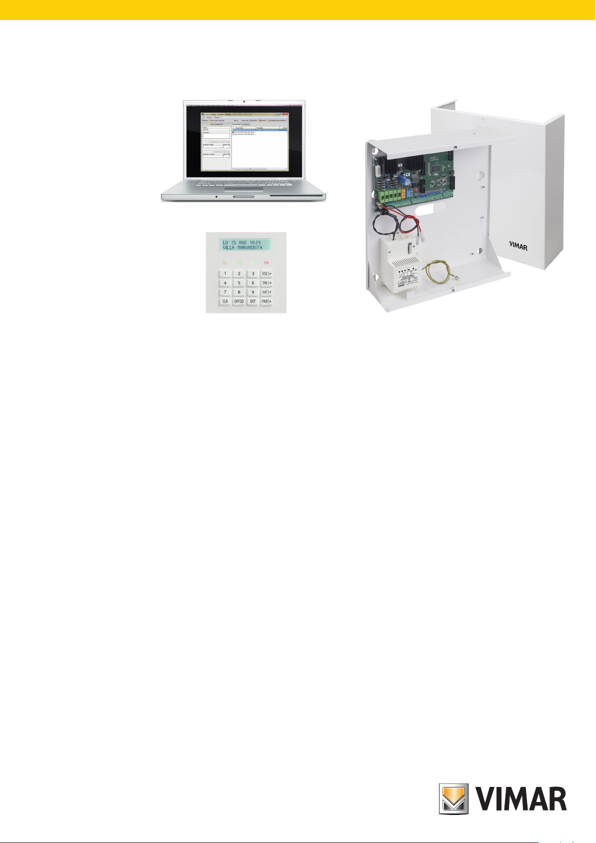
All control unit functions can be programmed using a computer which has the By-alarm Manager software installed or using one of the keypads connected to the control unit.
The control unit has an RS 485 input for connection to the bus on devices such as keypads, input expansion modules, output expansion modules, radio interfaces and readers.
The devices can be connected either to the RS485 bus or in parallel to the same conductors, respecting the codes on the terminals of the control unit and of the devices
themselves, namely:
• + with +
• - with -
• A with A
• B with B
For 12 Vdc power supply 0.50 mm2 conductors must be used and for the A and B sensors, 0.22 mm2 conductors; the shield must be connected to the negative with regard
to the control unit.
20
CN5
RS 485
D
EA B
OTHER RS485 BUS DEVICES
• The keypads have a special anti-tampering button which is activated when the container is opened and when the keypad is removed from the wall.
• The bridge on the side of the button closing causes the full exclusion of the keypad protection
Changing the keypad address.
1) Press and release the RESET push button (PB1) on the keypad card on the right-hand side near the microprocessor (see photo below).
2) Press the ENT button for approx. 1 s.
3) The display will show the physical address of the keypad.
4) Press the ENT button to enter the menu.
5) Using the and buttons, select the desired address.
6) Press ESC twice to confirm the address and exit the menu.
5

By-alarm
6

By-alarmBy-alarm
Section 1
Programming the control unit using the keypad 01705
7

By-alarm
Guidelines for programming the control unit using the keypad
Guidelines for programming the control unit using the keypad
1. With the power off, connect all devices (both those connected to the RS485 bus and those connected directly to the control unit).
2. The control unit is supplied pre-set to manage 6 zones as illustrated in chap. 3 of the installation manual.
If settings other than default are required, connect the 3k3 Ω resistors in the inputs for the unused devices in the control unit, and if the siren and relative tamper resistor have
not already been connected, connect the 3k3 Ω resistor directly between the T T terminals on the control unit.
N.B. When powering the system, if the resistors are not connected as described, the keypad will emit a tamper alarm and the procedure described in the control unit installation sheet must be followed (enter user ID to silence the alarm and enter installer ID to proceed with the settings).
3. Check that the jumpers required to exclude the control unit anti-tamper devices are present.
4. Power up the system.
5. Assign the relative ID address to each device connected to the RS485 bus (the assigning procedure can be done via the user interface or dip switch, as described in the
respective instruction sheets).
As illustrated in the installation manual, the ID assignment must always be sequential, starting with ID=1 for the first device, ID=2 for the second and so on for all devices of the
same category connected to the bus; two devices in the same category must always have different IDs (the radio frequency interfaces 01729 and input expansion modules
01709 and 01704 are devices in the same category and must therefore have a different ID while, for example, an input expansion module 01709, a reader 20478-1947814478 and an output expansion module 01710 may all have the same ID). If there is more than one keypad, select the one to be used for the settings, which will be assigned
ID=1; assign to the other keypads respectively ID=2, 3, etc.
6. Run the control unit self-learning procedure. This procedure can be done in two different ways (one alternative to the other):
Method 1 (from the control unit)
• Set dip switch 2 to ON and press the reset PB1 push button for at least 1 s.
• Once the control unit relays have completed a rapid switching sequence, place dip switch 2 to OFF and press the PB1 push button again.
The LED status of the device will indicate the correct outcome of the procedure (where present); for example, for radio frequency interface 01729:
- LED xed on = BUS connection problem.
- LED ashing 1 s ON and 1 s OFF = device not programmed.
- LED ashing briey every second = device programmed.
If the system has one or more radio frequency interfaces 01729 by default these are defined by the control unit as 8-channel interfaces; if you wish to use more than 8 chan-
nels you must eliminate the RADIO 8 interface and associate the respective ID to the RADIO 16 menu.
Mode 2 (from keypad)
Enter the Installer ID in the keypad chosen for the settings (default code 123456), and call up the menu SETTINGS – PROG. BUS 1 or 2 and for each device (reader, keypad,
etc.) specify how many are installed in the system, also indicating the respective ID.
For example, if there is an input expansion module with ID=1 and a radio frequency interface with ID=2 which has to manage 8 channels, proceed as follows:
- in the screen INP. EXP. 1-4 enter 1 and 2 to declare that the expansion modules on the bus (wired or radio) with ID 1 and 2.
- in the screen RADIO 8 (1-4) enter 2 to declare that the module with ID=2 is a radio frequency interface with 8 inputs.
Note: having received its own ID, the input expansion module 01709 automatically occupies 4 zones in the system however many devices will actually be connected and,
in the same way, the radio frequency interface will also occupy 8 or 16 according to what defined in the specific menu. It is very important to remember which zones are
occupied by the associated devices as, in the subsequent settings phases, it must be clear which one belongs to every device connected to the input expansion modules or
remote control interfaces; this must be compared with the maximum number of free zones available on the control unit in order to avoid associating additional devices which
will not trigger any alarm as they are not managed.
7. Following the instructions given in the radio frequency device instruction sheet, set the relative parameters (use of auxiliary inputs, radio range, etc.)
8. As described in the instructions for interface 01729 and other radio frequency devices, enter the settings paying attention to the fact that a device associated to the manage-
ment of auxiliary inputs on separate channels will occupy two or three zones: one for the device and one for each auxiliary input. For tidy programming, note the settings
considering that the first radio frequency device programmed will occupy the first zone associated to the interface 01729 and which, if its auxiliary input is programmed immediately afterwards, it will be associated to the subsequent alarm zone and so on.
Note: In the default settings, all the information on the reed/pyroelectric parameters and auxiliary inputs are managed on a single channel; with this setting, information on the
unbalanced zone will be sent to interface 01729 if one of the inputs on the radio frequency device is "unbalanced".
By appropriately programming detectors 01727 and 01728 it is possible to assign a separate radio channel to each input (programming done on the device); in this
case, it is also necessary to correctly associate the radio channels with separate zones to the interface 01729 (for example three radio channels on the detector 01727
are associated to three different zones).
9. Define the behaviour of the various zones in the SETTINGS-INPUTS-ZONE.PROG. menu (value=50 indicates a disabled zone) associating them to the required areas and
setting their functions (delays, etc.).
10. Define the Areas.
11. For each Area, define the associated zones belonging to the entry methods ON, INT and PAR .
12. Define the behaviour of Relay 1 to which the sirens are connected and that concerning any use of Relay 2.
13. Creation of user IDs and definition of the Areas and functions which can be associated to each code.
By default, user 1 is active on Area 1 with basic permissions (user ID 111111); the following procedure is used to create other users:
- enable the user;
- set the numerical code (which must be different from the default code);
- enter the user settings (assignment of permissions, etc.);
- associate a transponder key to the user if required.
14. Programme the transponder keys and radio frequency remote controls.
8

By-alarmBy-alarm
Guidelines for programming the control unit using the keypad
15. Associate the Areas and required functions to the transponder key and the remote control push buttons.
Notes:
• Each transponder key can be associated to a single user and therefore the relative permissions correspond to the user permissions. The procedure is as follows:
- acquire the tag (then associated to a specific user);
- indicate the settings for the reader on which the tag is enabled in the specific menu.
• As concerns the remote controls, simply associate the required function and entry area to each button.
16. Associate any keypad alarm signal (buzzer) to the required zones; it is possible to define the zones for which, in the event of an alarm, the keypad gives off an acoustic signal,
also setting the duration.
17. In outdoor sirens, set the acoustic signal duration in the event of an alarm (these are armed/disarmed by Relay 1 but in particular situations like a control unit failure or total
blackout of the system with flat batteries they can in turn ring for a set time).
18. If present, programme the GSM transmitter/receiver module 01706. In practice the device must be armed, the phone numbers entered, the user permissions correctly paired
and all programming required to manage the telephone part in the desired manner completed (SMS or voice).
19. If present, programme the voice synthesis module 01713 and record any vocal messages.
20. Having completed the programming, check the connections on the detectors connected to the control unit inputs, restore the anti-tamper devices via the jumpers, check
the siren connections and finally check the balancing on the sirens and devices with any resistors for double or triple balancing.
21. The new “map” of the bus devices can be downloaded to the PC using the By-alarm Manager software; before importing, enable the connection to the PC via the keypad:
- select the Settings e menu and press ENT.
- scroll through the menu as far as PC <--> Control unit and press ENT.
- press CLR to view YES.
- press ESC to exit the menu.
Finally, from the PC, run Connect -> Receive Programming and the programmed bus devices will be viewed in the specific menus.
Note: When programming with the By-alarm Manager software downloaded to the control unit, from the keypad you can view the features of the whole system (devices on
the bus, zone settings, association to areas, etc.).
9
By-alarm
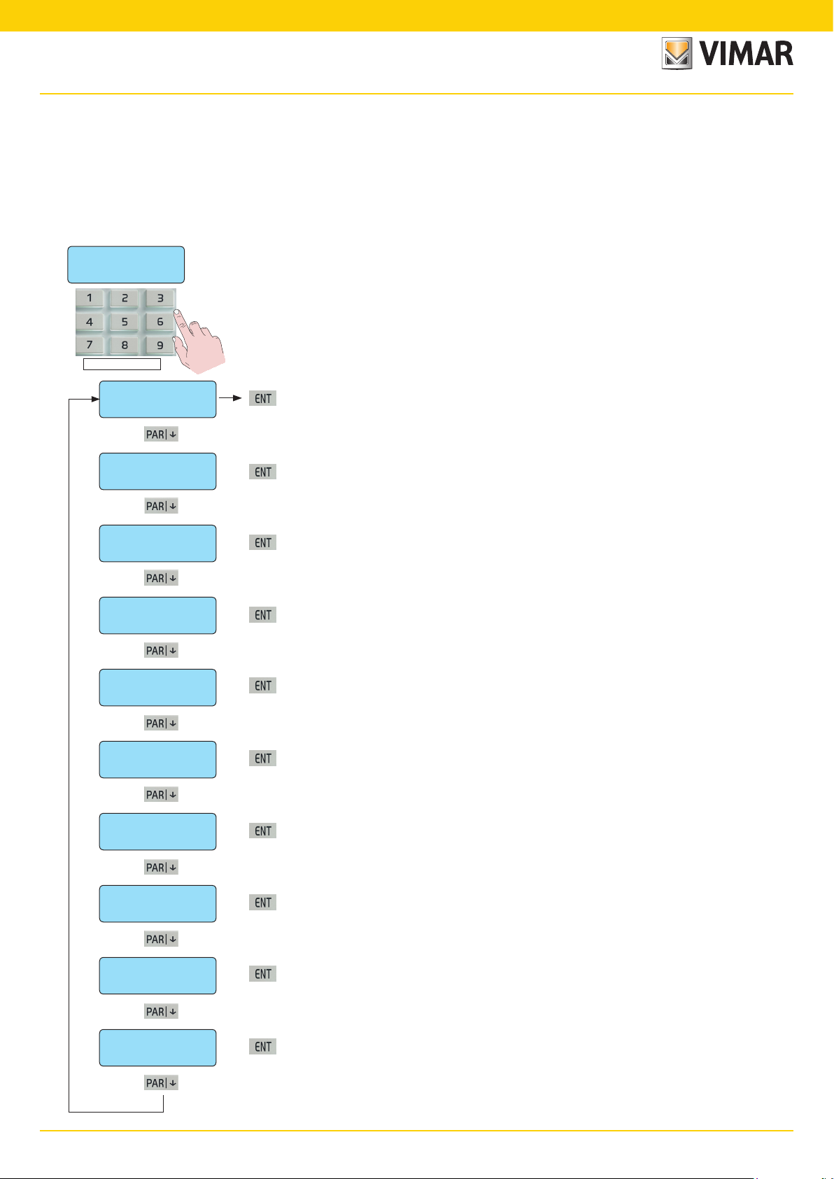
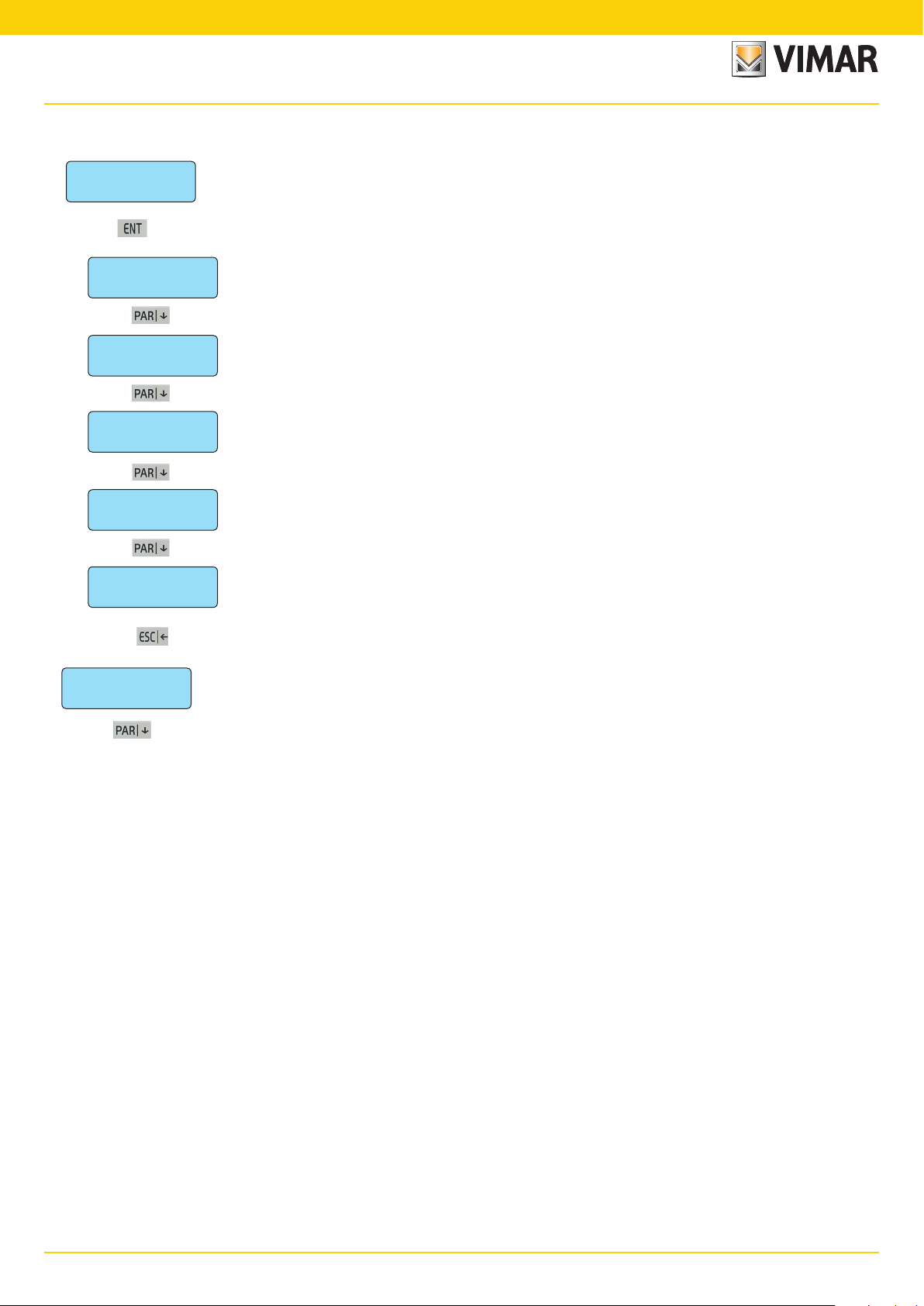
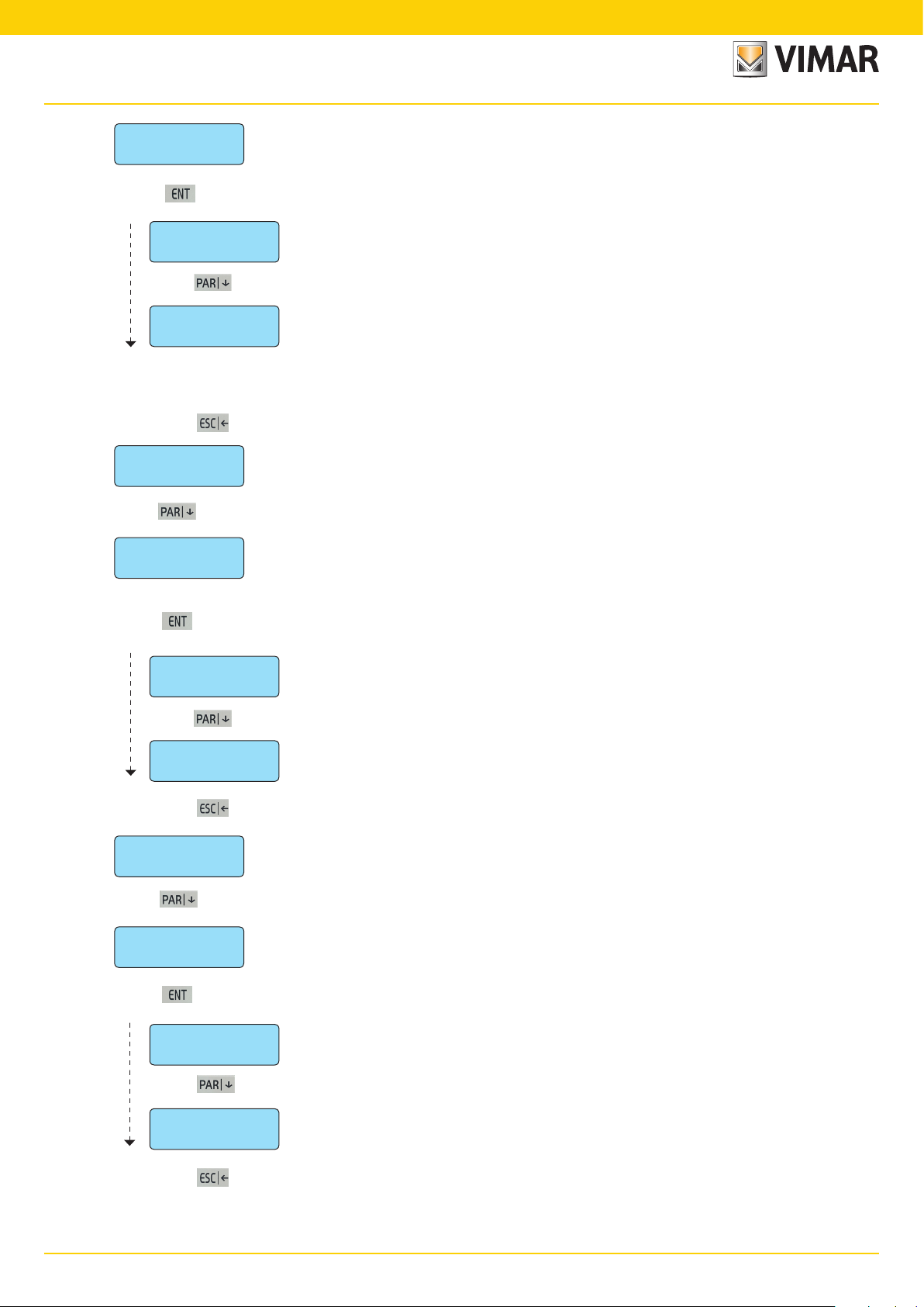
Primary Menu diagram
Primary Menu diagram
All control unit functions are programmed in 9 primary menus identifying as many function categories.
• The first control unit programming is done via the keypad which is assigned ID=1; therefore, if more than one keypad is installed in the system, the code allowing access
to the programming must be entered on the keypad with ID=1.
• The control unit is programmed by entering the Installer code on the keypad; by default this is 123456.
Menu navigation
• Use the navigation buttons ESC, ON, INT and PAR to surf through the Programming Menus:
• The ENT button confirms the data, CLR (clear) cancels it and ESC is used to exit the menu.
We 04 JUN 14:33
Vimar 01700 ENT
Installer ID
• The default code is programmed with the value: 123456
Installer ID
• System composition - page 11
ENT
Clock settings
Settings
• Setting the date and time - page 13
ENT
Inputs
• Input programming - page 14
ENT
Outputs
• Output programming - page 29
ENT
Codes
• Activation code programming - page 35
ENT
Times
• Time programming - page 41
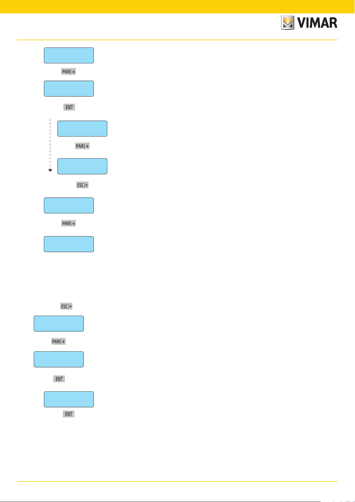
ENT
Settings
Clock settings
Inputs
Outputs
Codes
Times
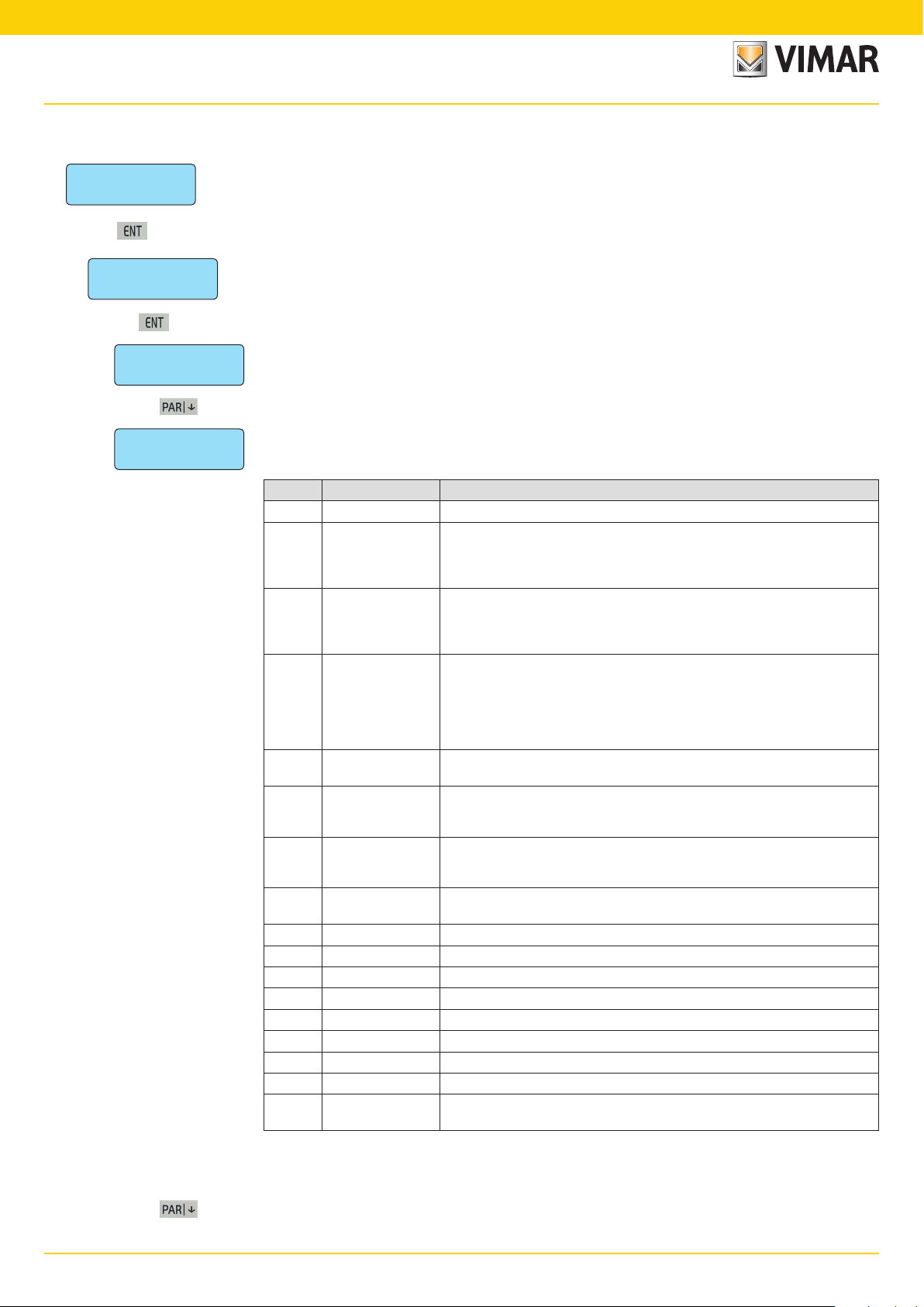
• Additional parameter programming - page 43
ENT
Scheduler
Controls
• Scheduler functions - page 57
ENT
Telephone
• Telephone connection functions - page 59
ENT
Controls
Scheduler
Telephone
• System diagnostics function - page 65
ENT
SYSTEM TEST
System test
10
By-alarmBy-alarm
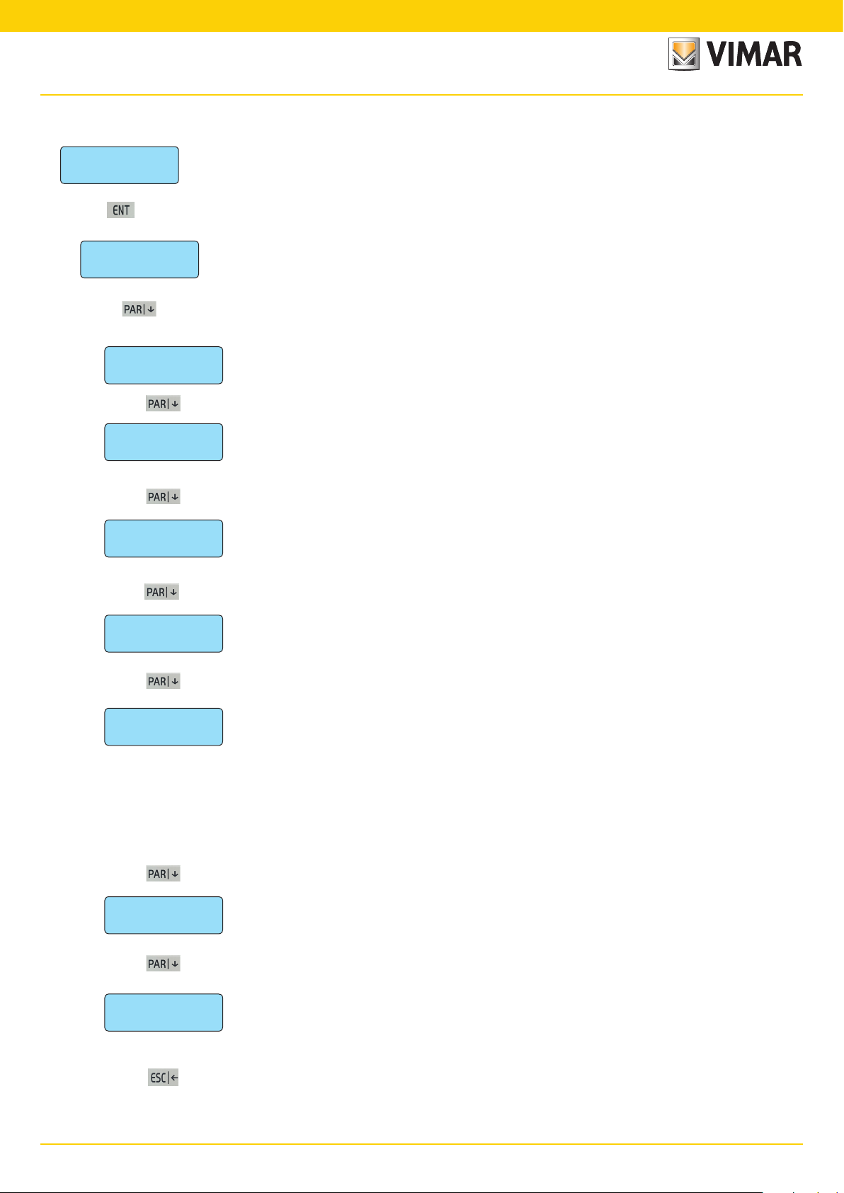
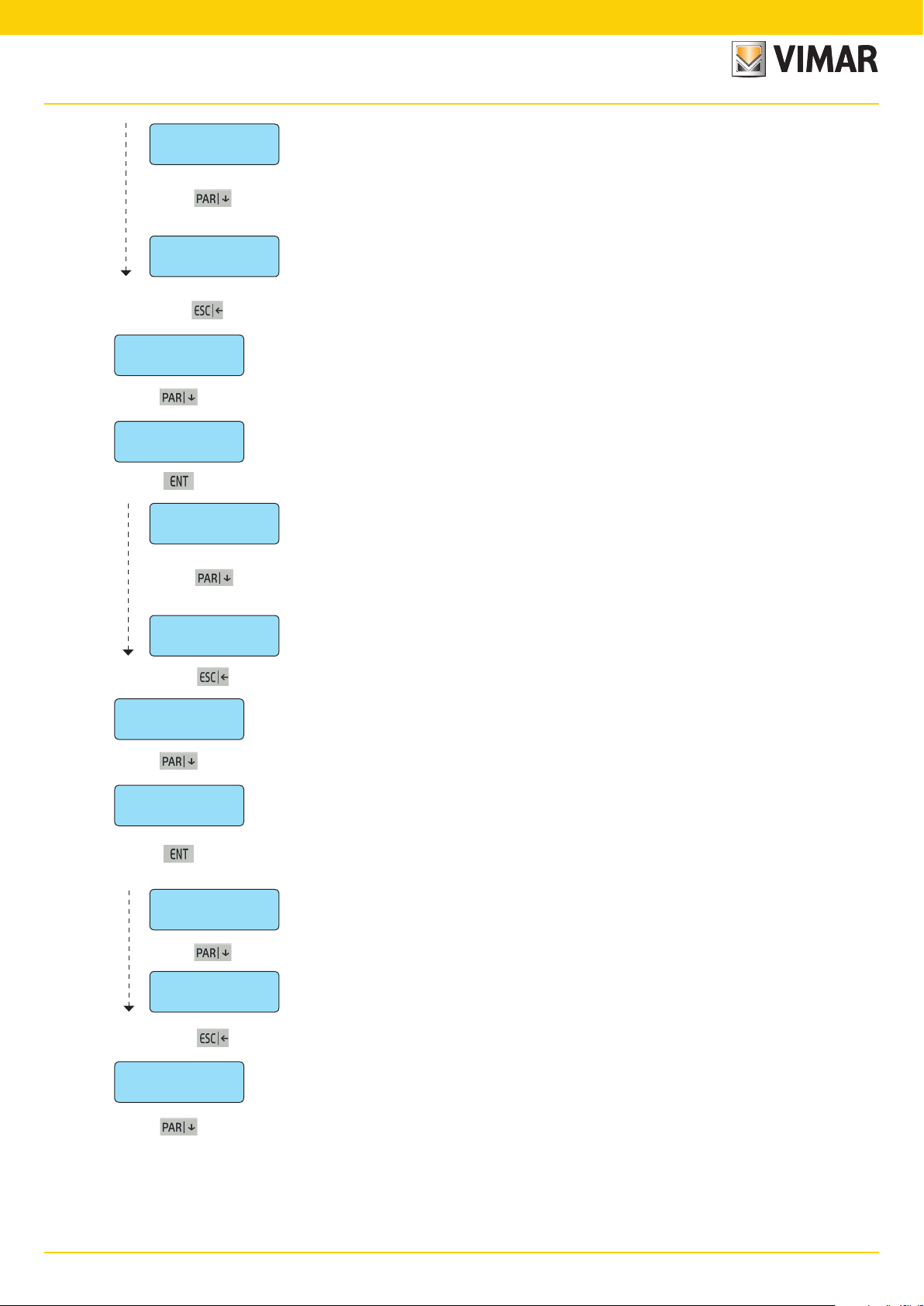
Programming the control unit devices
1. Programming the control unit devices
Settings
the addresses to the devices connected to the RS485 bus, run the self-learning procedure from the control unit and then
ENT
enter the menu to define the device categories.
• In the Settings menu press ENT to enter the settings.
progr. BUS
respective ID addresses assigned previously.
ENT
1. In Settings you set the composition of the system and the number of installed devices. Having manually assigned
1.1 In
BUS programming
you can programme all the devices connected to the RS485 bus, specifying for each one the
Keypads 1 - 4
• Enter number 1-2-3-4 relative to the installed keypads; the indicator will come on to confirm correct programming. To
the IDs of the input expansion modules and those of the radio frequency interfaces (if some of the IDs
assigned are not entered the control unit will not detect any alarms signalled by the associated device.
•
———
inp. exp. 1 - 4
——————
DETT. 01704 (1 - 4)
————
Radio 8 (1-4)
——————
Radio 16 (1-4)
1.1.1
1.1.2 Input expansion modules 01709 and radio frequency interfaces 01729 installed. In this menu enter both
1.1.3 In
• Press the number 1-2-3-4 for the installed expansions; the indicator will switch on to confirm the pro¬programming
1.1.4 In
1.1.5 In
——————
Keypads
• Press number 1-2-3-4 for the installed devices; the indicator will come on to confirm the correct programming. To
sions 01704 (each one will occupy 8 alarm zones).
interface present (each one will occupy 8 alarm zones).
• Press number 1-2-3-4 for the installed radio interfaces; the indicator will come on to confirm the correct programming.
nel interface present (each one will occupy 16 alarm zones). If there is a 16 channel radio frequency interface no other
interfaces or input expansion modules can be set as the maximum number of zones supported by the control unit has
been reached.
• Press number 1-2-3-4 for the installed radio interfaces; the indicator will come on to confirm the correct programming.
01705 installed.
deselect the keypad repeat the same operation.
deselect the device repeat the same operation.
DETT.01704 (1-4)
is correct. To deselect the module the same operation must be performed.
radio 8 (1-4)
To deselect the module repeat the same operation.
radio 16 (1-4)
To deselect the module repeat the same operation.
defines the input expansions 01704. It is necessary to indicate the ID of any existing input expan-
you define which are the radio frequency interfaces with 8 channels. Indicate the ID of any 8-channel
you define which are the radio frequency interfaces with 16 channels. Indicate the ID of any 16-chan-
IMPORTANT: The keypad is used to set up to 32 radio frequency channels; of these channels, those exceeding the
maximum number set on the radio frequency interface (i.e. more than 8 or 16 depending on the layout) are ignored by
the system.
out. exp. 1 - 6
READERS 1 - 4
- The reader is identified with the address given (see indications given in the control unit or reader installation manual).
——————
——————
to go back
1.1.6 Output expansion modules 01710 installed.
• Press number 1-2-3-4-5-6 for the installed expansions; the indicator will come on to confirm the correct programming.
To deselect the module repeat the same operation.
1.1.7 Readers 20478-19478-14478 installed.
• Write the number 1-2-3-4 for the readers installed; the indicator will come on to confirm the correct programming. To
deselect the reader repeat the same operation.
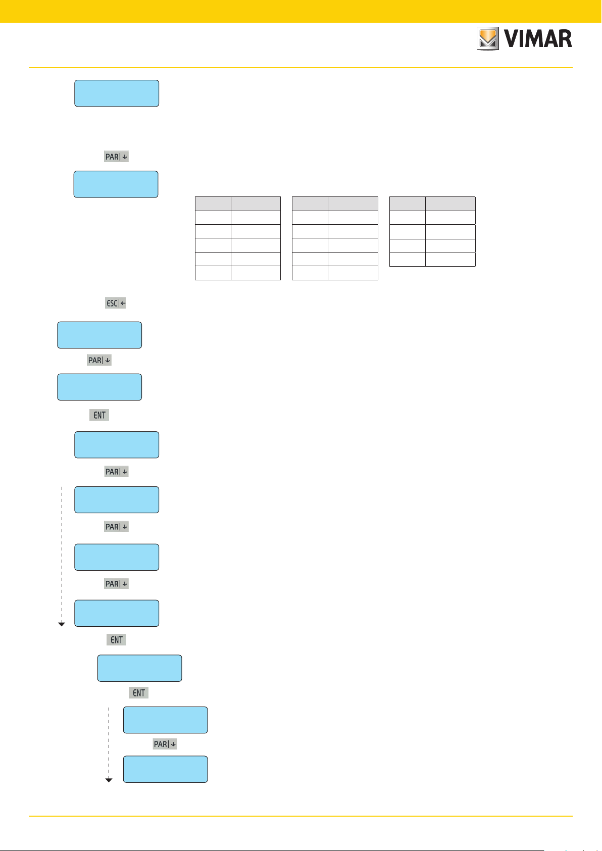
As there are no more parameters to be programmed, press ESC| to return to the previous level of the RS 485 BUS
programming menu.
11
By-alarm
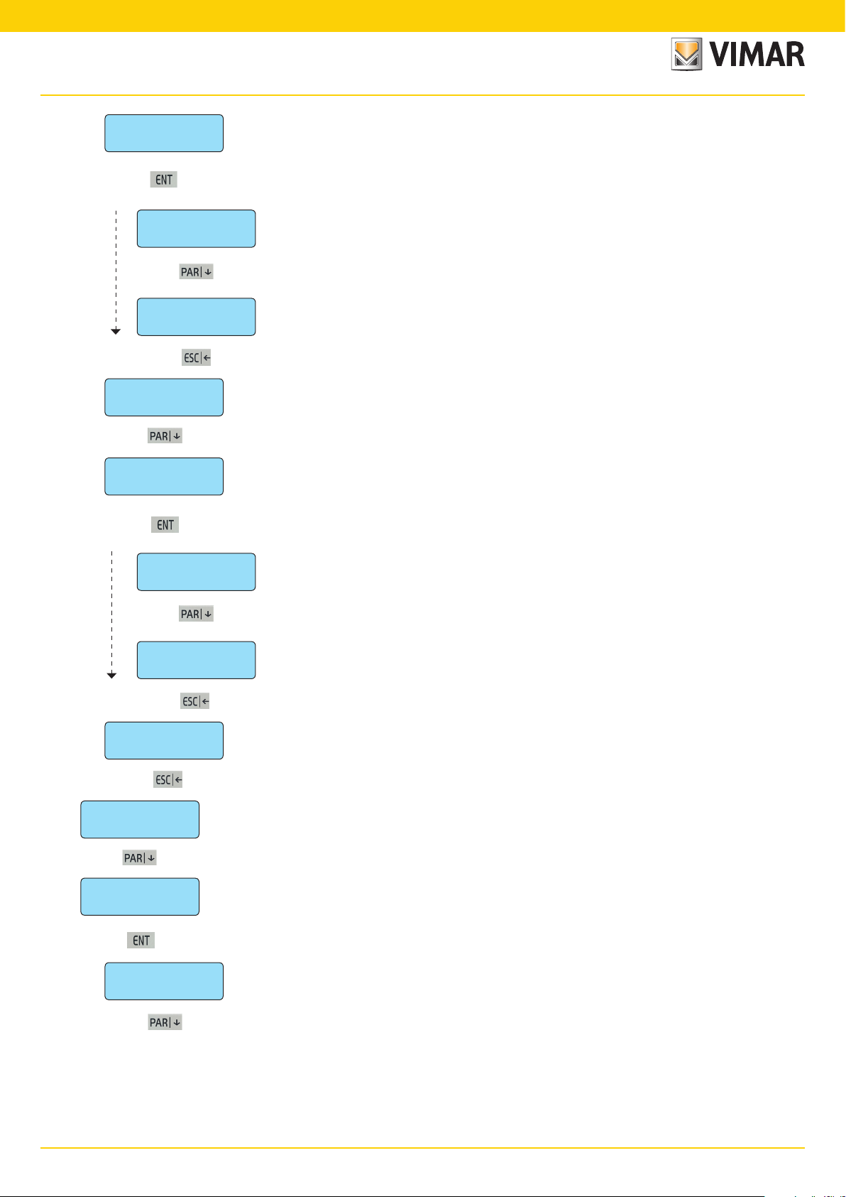
Programming the control unit devices
progr. BUS
ENT
From the progr. BUS menu press the down arrow PAR| to access the programming procedures for the other control unit devices.
PSTN line
• Press CLR to edit the settings.
YES
GSM module
• Press CLR to edit the settings.
0 (MAX 4)
• Programme the telephone company of the SIM inserted in the GSM module.
• Write the company number directly, consulting the following table:
1.2 Select YES if the PSTN LINE circuit in the control unit for connecting to the PSTN analogue phone line must be enabled.
1.3 Select the GSM company interface 01706 to be enabled (set the number of GSM modules present).
Prog. Function type Phone company
0 NO GSM No company selected.
1 TIM TIM mobile phone company.
2 VODAFONE VODAFONE mobile phone company.
3 WIND WIND mobile phone company.
PC <--> Control unit
• Press CLR to change the settings.
NO
Select YES if you want a direct connection between a
• Press CLR to edit the settings.
- The connection between the PC and the control unit must be done via the interface art. 01725.
- For interactive connection between the control units and the PC install and programme the By-alarm Manager software.
- For the installation and recording procedures, follow the indications given in the By-alarm Manager software manual.
Select NO if you wish to do the programming from the keypad
• Press CLR to edit the settings.
CONFORM EN50131
NO
to go back As there are no more parameters to be programmed, press ESC| to return to the previous level of the Settings menu.
1.4 Select NO if you wish to do the programming from the keypad
PC <--> Control unit
1.5 Select NO if you do not want the system to comply with the indicated standard.
.
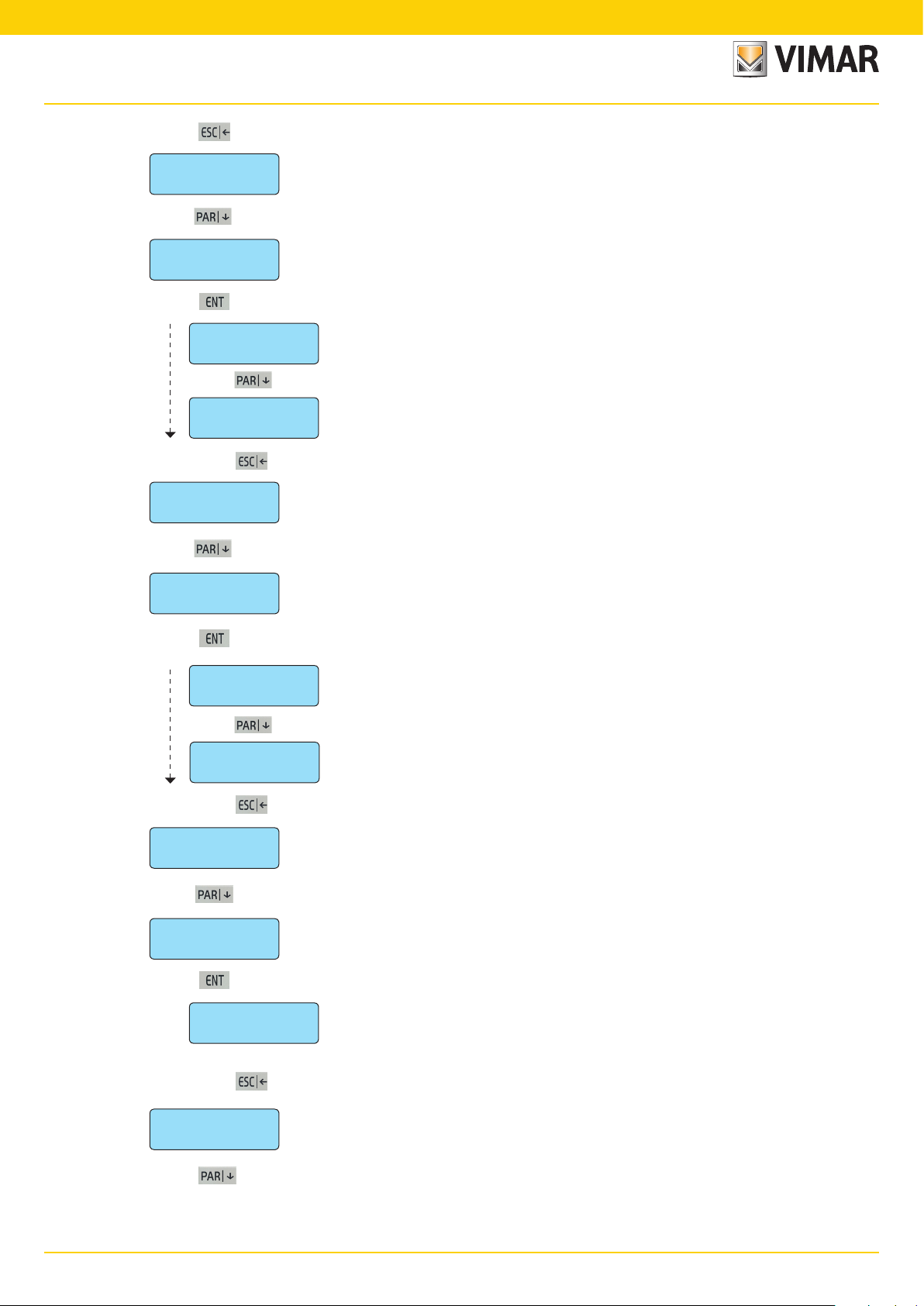
Settings
ENT
From the
Settings
menu use the down arrow PAR| to go to the control unit clock settings menu.
12
By-alarmBy-alarm
Clock settings
2. Internal clock settings
2. In
Clock settings
• From the
ENT
Time
• Enter the time directly.
08 (max. 23)
Minute
• Enter the minutes directly.
12 (max. 59)
Day
• Enter the day directly.
5 (max. 31)
month
• Enter the month directly.
5 (max. 12)
Clock settings
Clock Settings
2.1 Setting the current
2.2 Setting the current
2.3 Setting the current
2.4 Setting the current
you can programme the time and date of the control unit clock.
menu press ENT to enter the settings.
Time
.
Minute
.
Day
.
MONTH
.
year
• Enter the year directly.
3 (max. 99)
to go back As there are no more parameters to be programmed, press ESC| to return to the previous level of the Clock Settings menu.
Clock settings
ENT
From the
2.5 Setting the current
Clock Settings
menu use the down arrow PAR| to view the control unit inputs programming menu.
Year
.
13
By-alarm
Input programming
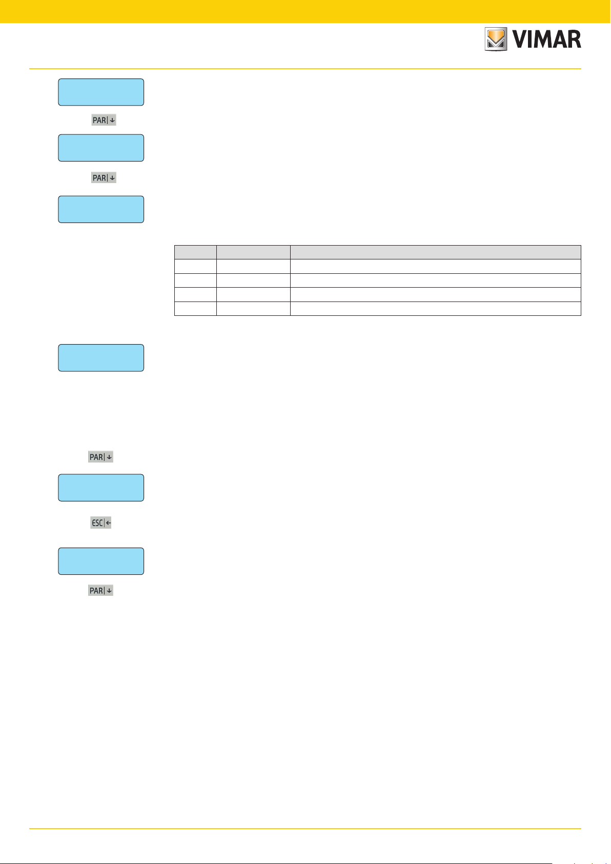
3. Input programming
Inputs
• From the
ENT
Prog. zone
ENT
Num. Zone: 1
• Write the number of the zone to be programmed.
(MAX 24)
Zone type:
0 (MAX 53)
3. In
3.1 From the
inputs
set all the control unit input parameters.
inputs
menu press ENT to enter the first zone programming menu.
zone programming
3.1.1 Select the
3.1.2 Select the
• Write the number of the required mode by consulting the table below.
Progr. Zone type Description
0 Instantaneous With the control unit on, an alarm is generated as soon as the zone is unbalanced.
1
2 - 3 Timed 1 -2
4
5
6 24 hours
7 Anti-Tampering
8 - 9 - 10
11 - 18 Suspension Area 1-8
19 Panic reset delayed If the zone is unbalanced, it cancels the anti-coercion procedure.
20 - 29 Start macro 1-10 If the zone is unbalanced, the associated macro is activated.
30 - 39 Stop macro 1-10 If the zone is unbalanced, the associated macro is locked.
40 - 49 Reset Macro 1 - 10 If the zone is unbalanced, the associated macro is reset.
50 Not used
51 Sensor fault If the zone is unbalanced a Sensor fault signal is generated (EN-50131).
52 Anti-theft device fault If the zone is unbalanced an Anti-theft device fault signal is generated (EN-50131).
53 Siren fault
zone number
type of zone
Instantaneous with
automatic exclusion
Timed with automatic
exclusion/re-inclusion
Timed conditioned
instantaneous
On
ON/INT/PAR
menu press ENT to enter the programming modes for each zone.
to be programmed.
associating it to the operating mode.
If when entering the group the input is unbalanced, the zone is automatically excluded
and the event is stored in the events log.
It is re-included automatically when the control unit is turned off.
Note: if used the IMQ type-approval expires.
When the control unit is turned on the exit time 1 - 2 is activated.
At the end of this time, a subsequent line unbalancing will enable the re-entry time 1 - 2.
At the end of the re-entry time, if the control unit is not turned off an alarm sequence is
enabled.
The zone becomes active after a programmable “exit” time, allowing you to leave having
inserted the group; if at the end of this time the zone is unbalanced it is automatically
excluded. It will be re-included after the next re-balancing. The zone generates an alarm
after a programmable delay calculated from the time in which the entry is unbalanced;
during this delay it is possible to disconnect the group without generating alarms.
Note: if used the IMQ type-approval expires.
Instantaneous line which is automatically excluded during the exit and re-entry time of a
timed line 1 or 2.
Line always active, its unbalancing causes an alarm even if the control unit is turned off.
Note: to maintain IMQ type-approval: if this mode is used with the anti-theft function, the
zones must be associated to all phone numbers.
Additional anti-tampering line; cannot be excluded with "OFF ZONE" operation from
keypad and when unbalanced it causes an anti-tampering alarm even when the control
unit is turned off.
Remote ON line in mode ON, INT, PAR. When unbalanced it causes the control unit to
come on in one of the possible modes.
If the zone is unbalanced a Siren fault signal is generated (EN-50131). To be used in the
input to which the LV output of the siren 01715 is connected.
The area suspension is an operating mode which can be used to interrupt the scheduler cycle arming and disarming. After the
This guarantees that in the event of more than one event at the same time panic, theft and tampering are transmitted as a priority.
suspension the control unit goes to the state set in the programming for the current time band.
Important: Panic, theft, tampering events must be associated to at least the first phone number.
14
By-alarmBy-alarm
Input programming
Zone unbalancing
• Write the number or required unbalancings.
1 (max. 10)
dur. of switch alarm
3.1.3 This is the number of
3.1.4 This is the duration of a single unbalancing for it to be considered valid.
8 (1=2ms)
to go back
Prog. zone
ENT
From the
zone unbalancings
Note: the pulse count only applies to the alarm signal and not to tampering and/or masking that are signalled with the
first pulse.
CAUTION: This function cannot be used to connect inert sensors or sensors for roll-up shutters at the inputs
from L1 to L8 of the control unit as these detect unbalancings with a time greater than 120 ms and which cannot be calibrated.
The acquisition times are shown in the following tables:
Prog. Description
0 1 ms
1 2 ms
2 5 ms
3 10 ms
4 20 ms
As there are no more parameters to be programmed, press ESC| to return to the previous level of the Zone Programming
menu.
Zone Programming
menu use the down arrow PAR| to go to the Area Settings menu.
Prog. Description
required to trigger the control unit alarm.
Prog. Description
5 40 ms
6 80 ms
7 120 ms
8 160 ms
9 200 ms
10 600 ms
11 1 s
12 2 s
13 4 s
3.2 In
areas
• From the
ENT
area 1
ENT
area 2
ENT
area 7
ENT
area 8
ENT
Active in ON
ENT
AREAS
3.2.1 Partition Area refers to the possibility to group zones to obtain different systems with a single control unit.
• From the
- The control unit has 8 Areas and for each one must be programmed or associated to the required functions. If you do
- The arming methods are used to customise the safety system operation; the control unit 01700 has 3 arming modes
- If the same zone is associated to 2 or more different areas for the same arming mode, a shared zone is obtained; the
3.2.1.1 In
Zones 1 - 8
• The symbol will come on to confirm the association.
————————
Zones 17 - 24
————————
you programme all the settings for the possible control unit partitions.
AREAS
menu press ENT to enter the first Zone Programming menu.
area 1
to the
area 8
menu press ENT to enter the Programming menu for the 8 possible areas.
not need to use more than one area, simply do not associate any function to the areas from 2 to 8.
which are identified with as many push buttons on the keypad: ON (total arming), INT (internal arming) and PAR (partialised arming). Every area can therefore be independently placed in armed state using one of the 3 different modes
at a time.
shared zone will be active only when all the associated areas are in the ON state; this automation makes programming easier when there are several systems with a shared entrance. Obviously, there may be more than one shared
zone.
active in on
• Press ENT to enter the settings.
3.2.1.1.1 Select which zone will be
• To remove the association write the required number.
you programme the zones associated to the arming in ON mode.
active in on
• Write the number 1-2-3-4-5-6-7-8 for the zones to be associated.
when the Area is armed in ON mode.
15
By-alarm
Input programming
to go back As there are no more parameters to be programmed, press ESC| to return to the Active in ON menu.
Active in ON
ENT
From
Active in INT
ENT
• The symbol will come on to confirm the association.
Zones 1 - 8
————————
• To remove the association write the required number.
active in ON
3.2.1.2 In
• Press ENT to enter the settings.
3.2.1.2.1 Select which zone will be
Zones 17 - 24
————————
to go back As there are no more parameters to be programmed, press ESC| to return to the Active in INT menu.
Active in INT
ENT
From
Active in PAR
ENT
active in int
3.2.1.3 In
• Press ENT to enter the settings.
use the down arrow PAR| to go to the Zone Activation Menu in INTernal.
active in on
active in par
you programme the zones associated to the arming in ON mode.
active in int
• Write the number 1-2-3-4-5-6-7-8 for the zones to be associated.
use the down arrow PAR| to go to the Zone Activation menu in PARtialised
you programme the zones associated to arming in PAR mode.
when the Area is armed in INT mode.
• The symbol will come on to confirm the association.
• To remove the association write the required number.
————————
Zones 1 - 8
3.2.1.3.1 Select which zone will be
• Write the number 1-2-3-4-5-6-7-8 for the zones to be associated.
active in int
when the Area will be armed in PAR mode.
Zones 17 - 24
————————
to go back As there are no more parameters to be programmed, press ESC| to return to the Active in PAR menu.
Active in PAR
ENT
From
keypads 1 - 4
ENT
• The symbol will come on to confirm the association.
• To remove the association write the required number.
keypads 1 - 4
——————
active in par
3.2.1.4 In
use the down arrow PAR| to go to the Keypad Association menu.
keypads 1 - 4
• Press ENT to enter the settings.
3.2.1.4.1 Select which
programme the association between the chosen Area and the installed keypads.
keypad 1 - 4
• Write the number 1-2-3-4 for the keypads which must be associated.
will be associated to the chosen Area.
to go back As there are no more parameters to be programmed, press ESC| to return to the Keypads menu.
eypads 1 - 4
K
ENT
From
keypads 1 - 4
16
use the down arrow PAR| to go to the readers programming menu.

By-alarmBy-alarm
Input programming
readers 1 - 4
ENT
• The symbol will come on to confirm the association.
• To remove the association write the required number.
readers 1 - 4
——————
3.2.1.5 In
readers 1 - 4
• Press ENT to enter the settings.
3.2.1.5.1 Select which
programme the association between the chosen Area and the installed readers.
• Write the number 1-2-3-4 for the reader to be associated.
readers 1 - 4
reader will be associated to the chosen Area.
readers 1 - 4
ENT
to go back As there are no more parameters to be programmed, press ESC| to return to the Area Programming menu level.
Area 1
ENT
to go back As there are no more parameters to be programmed, press ESC| to return to the Area Programming menu level.
to go back
areas
ENT
From
Alarm options
• From the
ENT
Alarm memory
• Press ENT to enter the settings.
ENT
area 02
3.3 In
3.3.1 In
use the down arrow PAR| to go to the Alarm Options Settings menu.
alarm options
memo alarm
As there are no more parameters to be programmed, press ESC| to return to the reader programming menu
level.
you programme all the function to be associated to the control unit alarm state.
alarm options
menu press ENT to enter the settings.
make the events memory record the alarm.
Zones 1 - 8
• Write the number 1-2-3-4-5-6-7-8 for the zones to be associated.
• The symbol will come on to confirm the association.
• To remove the association write the required number.
————————
Zones 17 - 24
to go back As there are no more parameters to be programmed, press ESC| to return to the Alarm Memo Menu.
Alarm memory
ENT
From
————————
3.3.1.1 Select which
memo alarm
ZONE 1 - 8
use the down arrow PAR| to view the Reset Memo Menu.
must record the alarm in the control unit events memory.
17
By-alarm
Input programming
Reset memory
• Press ENT to enter the settings.
ENT
Zones 1 - 8
• The symbol will come on to confirm the association.
• To remove the association write the required number.
————————
Zones 17 - 24
3.3.2 In
reset memo
3.3.2.1 Select which zone must
• Write the number 1-2-3-4-5-6-7-8 for the zones to be associated.
Events Memory: • the control unit has a memory used to record all the fault, arming and disarming events with date and
————————
to go back As there are no more parameters to be programmed, press ESC| to return to the Memo Alarm Reset menu.
Reset memory
ENT
From
activate buzzer
To set the buzzer length see chap. 6 of this manual.
ENT
• Press ENT to enter the settings.
memo reset
3.3.3 In
use the down arrow PAR| to view the Buzzer Activation menu.
buzzer active
make the events memory record the alarm reset.
record the alarm reset
time, the codes entered and alarm and zone reset states, if the function described above is selected
in programming; there are 500 recorded events which are automatically updated, deleting the oldest
ones.
• the events in the memory can be consulted directly by the user and will be shown on the control
keypad in the following form:
you programme which of the programmed zones will activate the keypad buzzer in the event of an alarm.
in the control unit events memory.
Zones 1 - 8
• The symbol will come on to confirm the association.
• To remove the association write the required number.
————————
Zones 17 - 24
3.3.3.1 Select which zone must
• Write the number 1-2-3-4-5-6-7-8 for the zones to be associated.
activate the buzzer
on the keypad in the event of an alarm.
————————
to go back As there are no more parameters to be programmed, press ESC| to return to the Keypad buzzer activation menu.
activate buzzer
ENT
From
double eol
• Press ENT to enter the settings.
ENT
Zones 1 - 8
• The zones not associated to double balancing will automatically be programmed for single balancing.
• The symbol will come on to confirm the association.
• To remove the association write the required number.
————————
Zones 17 - 24
buzzer active
3.3.4 In
use the down arrow PAR| to view the Double Balancing menu.
double eol
3.3.4.1 Select which zone must be programmed for
you programme the zones with double balancing.
• Write the number 1-2-3-4-5-6-7-8 for the zones to be associated.
double balancing
————————
.
18
to go back As there are no more parameters to be programmed, press ESC| to return to the Double Balancing menu
By-alarmBy-alarm
Input programming
double eol
ENT
From
triple eol
• Press ENT to enter the settings.
ENT
Zones 1 - 8
• To be associated to triple balancing, the zones must also be associated to double balancing.
————————
• To remove the association write the required number.
Zones 17 - 24
double eol
3.3.5 In
use the down arrow PAR| to view the Triple Balancing menu.
triple eol
3.3.5.1 Select which zone must be programmed for
• Write the number 1-2-3-4-5-6-7-8 for the zones to be associated.
• The symbol will come on to confirm the association.
————————
to go back As there are no more parameters to be programmed, press ESC| to return to the Triple Balancing menu.
triple eol
ENT
you programme the zones with triple balancing.
triple balancing
.
From
Alarm coding
• Write the number of alarms required to activate the Alarm Coding function.
- After the programmed number of alarms in the same zone, the alarm relay will no longer be activated, the events
- The counter reset and re-inclusion of the zone will occur when disarming the control unit or if an alarm is triggered in
- All zones programmed with 24 hour type and tamper functions are excluded automatically from the alarm coding.
- Enter zero to completely disable the function.
3 (max. 10)
to go back As there are no more parameters to be programmed, press ESC| to return to the Alarm Options menu.
3.3.6 In
triple eol
use the down arrow PAR| to view the Alarm Coding menu.
alarm coding
memory records the zone bypassed and the sum of the events and a single phone call will be made notifying the
zone bypassed.
another zone.
with a number greater than zero, you enable the multiple alarm control function.
Alarm options
ENT
From
Auxiliary options
• From the
ENT
Buzzer in
ENT
alarm options
3.4 In
3.4.1 In
use the down arrow PAR| to go to the Auxiliary Options menu.
Auxiliary options
auxiliary options
buzzer in
• From the
buzzer in
you programme the auxiliary parameters for the zones.
menu press ENT to enter the settings.
you programme which zones programmed with timer must make the keypad buzzer ring.
press ENT to enter the settings.
19

By-alarm
Input programming
Zones 1 - 8
• The symbol will come on to confirm the association.
• To remove the association write the required number.
to go back As there are no more parameters to be programmed, press ESC| to return to the Buzzer IN menu.
Buzzer in
ENT
————————
- The function can be left active for all zones as only the timed zones will make the keypad buzzer ring.
Zones 17 - 24
————————
3.4.1.1 Which zone must activate the
• For each zone group, write the number 1-2-3-4-5-6-7-8 for the input lines that must activate the buzzer.
buzzer in
on the keypads to indicate the entry time of a timed zone.
From the
Buzzer out
ENT
Zones 1 - 8
• The symbol will come on to confirm the association.
• To remove the association write the required number.
————————
- The function can be left active for all zones as only the timed zones will make the keypad buzzer ring.
3.4.2 In
Zones 17 - 24
————————
to go back As there are no more parameters to be programmed, press ESC| to return to the Buzzer OUT menu.
Buzzer out
ENT
From the
The
chime
ENT
chime
continuous and you must enter a User ID to silence it.
3.4.3 In
buzzer in
• From the
3.4.2.1 Which zone must activate the
buzzer out
is a function that makes the keypad buzzer ring when, with the system disarmed, the zone is unbalanced. The sound is
• From the
menu use the down arrow PAR| to view the Buzzer OUT menu.
buzzer out
chime
you programme which zones programmed with timer must make the keypad buzzer ring.
buzzer out
• For each zone group, write the number 1-2-3-4-5-6-7-8 for the input lines that must activate the buzzer.
menu use the down arrow PAR| to go to the Chime menu.
you programme which zones will activate the Chime function.
chime
menu press ENT to enter the settings.
buzzer out
menu press ENT to enter the settings.
on the keypads to indicate the exit time of a timed zone.
Zones 1 - 8
• The symbol will come on to confirm the association.
• To remove the association write the required number.
————————
Zones 17 - 24
————————
to go back As there are no more parameters to be programmed, press ESC| to return to the Chime menu level.
chime
ENT
From the
3.4.4 In
20
door
ENT
3.4.3.1 • For each zone group, write the number 1-2-3-4-5-6-7-8 for the input lines that must activate the buzzer.
chime
use the down arrow PAR| to go to the Door menu.
door
you programme which zones activate the Chime function.
• From the
door
menu press ENT to enter the settings.
By-alarmBy-alarm
Input programming
Zones 1 - 8
————————
• The symbol will come on to confirm the association.
• To remove the association write the required number.
Zones 17 - 24
————————
to go back As there are no more parameters to be programmed, press ESC| to return to the Door menu level.
door
ENT
3.4.4.1 The
door
is a function that makes the keypad buzzer ring when, with the system disarmed, the zone is
unbalanced.
The sound is continuous and you must enter a User ID to silence it.
• For each zone group, write the number 1-2-3-4-5-6-7-8 for the input lines that must activate the buzzer.
From the
Ding dong
ENT
Zones 1 - 8
————————
3.4.5 In
• The symbol will come on to confirm the association.
• To remove the association write the required number.
Zones 17 - 24
————————
to go back As there are no more parameters to be programmed, press ESC| to return to the Ding Dong menu.
Ding dong
ENT
From the
Zone not bypassable
ENT
3.4.6 In
door
use the down arrow PAR| to view the Ding Dong menu.
door
you programme which zones activate the Chime function.
• From the
3.4.5.1 The
ding dong
• From the
door
menu press ENT to enter the settings.
Ding Dong
disarmed, the zone is unbalanced.
The sound will be automatically interrupted even if the zone stays unbalanced.
• For each zone group, write the number 1-2-3-4-5-6-7-8 for the input lines that must activate the buzzer.
use the down arrow PAR| to view the Zone not Bypassable menu.
Zone not Bypassable
Zone not Bypassable
is a function that makes the keypad buzzer ring for two seconds when, with the system
you programme the zones that cannot be bypassed.
menu press ENT to enter the settings.
Zones 1 - 8
• The symbol will come on to confirm the association.
• To remove the association write the required number.
————————
- The zones programmed in Tamper mode can in any case never be bypassed.
Zones 17 - 24
————————
to go back As there are no more parameters to be programmed, press ESC| to return to the Zone not Bypassable level.
Zone not bypassable
ENT
From the
3.4.6.1 By selecting the
• For each zone group, write the number 1-2-3-4-5-6-7-8 for the input lines which cannot be bypassed.
Zone not Bypassable
Zone not Bypassable
use the down arrow PAR| to view the Zones programmed for pre-alarm menu
the zone can never be bypassed, even by the User.
21
By-alarm
Input programming
pre-alarm
ENT
Zones 1 - 8
————————
• The symbol will come on to confirm the association.
• To remove the association write the required number.
- The coercion zone may be any line in the control unit whatever mode it is programmed in.
Zones 17 - 24
————————
to go back As there are no more parameters to be programmed, press ESC| to return to the Coercion Menu level.
PRE-ALARM
ENT
3.4.7 In
pre-alarm
• From the
3.4.7.1 The unbalancing of the zone associated to the
- The Coercion procedure can only be stopped by unbalancing a zone programmed with the Delayed Panic
you programme the zones with Coercion function.
pre-alarm
sends programmed telephone calls.
• For each zone group, write the number 1-2-3-4-5-6-7-8 for the input lines that must activate the phone calls.
Reset function.
menu press ENT to enter the settings.
PRE-ALARM
function triggers a silent alarm which consequently
From the
Final Door
ENT
3.4.8 In
Zones 1 - 8
————————
• The symbol will come on to confirm the association.
• To remove the association write the required number.
- The function must necessarily be associated to a zone programmed in Timed mode (see page 5).
Zones 17 - 24
————————
to go back As there are no more parameters to be programmed, press ESC| to return to the Final Door menu level.
Final Door
ENT
to go back As there are no more parameters to be programmed, press ESC| to return to the Auxiliary Options menu level.
Auxiliary options
ENT
PRE-ALARM
timer (exit time) when it is balanced again (this application is useful for entrance doors, doors onto corridors, etc.).
• From the
3.4.8.1 The zone associated to the
- This is a typical function for an entrance door when it is closed after having switched the system on, it im-
use the down arrow PAR| to view the Menu of the Zones programmed as Final Door.
final door
you programme the zones to be considered as the last exit. In practice it is a zone that interrupts the
final door
re-balanced.
• For all zones, write the number 1-2-3-4-5-6-7-8 for the input lines considered “last exit”.
mediately stops the exit time.
menu press ENT to enter the settings.
final door
function immediately stops the exist time of a timed line when this is
From
Tamper
ENT
• From each
Control unit tamper
ENT
Dedicated control unit anti-tamper line; in the terminal block, identified by codes TT.
Buttons protecting the control unit container from being opened or pulled off the wall.
auxiliary options
3.5 By
Tamper
procedure.
•
Tamper control unit
use the down arrow PAR| Anti-tamper settings menu.
we refer to all anti-tamper functions of the system of any kind, although they all follow the same programmed
Tamper
menu press ENT to enter the settings.
: there are two types, but both are identified in the same way.
22
 Loading...