

Page 1
Manuale installatore - Installer guide
Manuel installateur - Technisches Handbuch
Instrucciones instalador - Manual do instalador
Poste mains libres Sound System (pour montage à encastrer / version de table / pour montage mural en saillie)
6600
Art. 6600/AU - 660A/AU - 6700/AU
Citofono vivavoce Sound System (da incasso parete / da tavolo / da esterno parete)
Sound System speakerphone interphone (flush-mounted / desk-top version / surface wall-mounting)
Freisprech-Haustelefon Sound System (für UP-Montage / als Tischgerät / für AP-Montage)
Portero aut. manos libres Sound System (de empotrar / de sobremesa / de superficie)
Telefone alta-voz Sound System (para montagen de embeber / versão de mesa / para montagem saliente)
Page 2
6600
59mm
10mm
141 mm
125mm
125
mm
40mm
141mm
139
mm
Il manuale istruzioni è scaricabile dal sito www.vimar.com
C
D
F
G
D
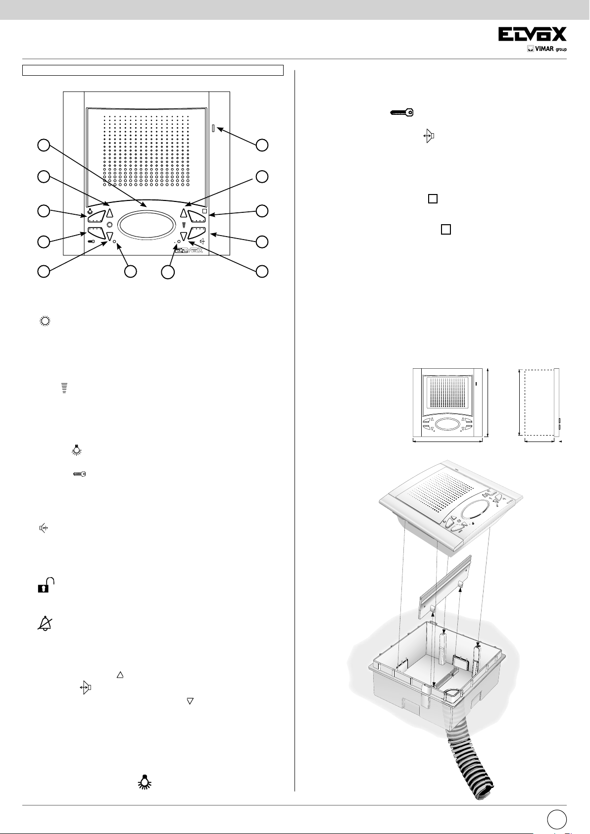
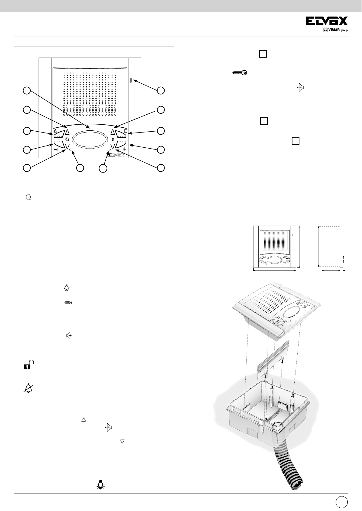
PULSANTI E E REGOLAZIONI
B) Microfono.
C) Altoparlante.
D)
Quando il citofono non è inserito i pulsanti permettono la selezione della
Coppia di pulsanti.
melodia per la sola chiamata da posto esterno. Per programmare la
melodia: mantenere premuto per almeno 2 secondi uno dei 2 pulsanti,
ripremere ripetutamente i pulsanti per selezionare la melodia interessata.
L
M
B
E
H
I
E
6: Positivo alimentazione (tensione minima in arrivo 15V c.c.)
7: Seconda funzione ausiliaria
mento è deciso dal microinterruttore posto sul retro del citofono)
8: Chiamata dalla targa esterna
9: Pulsante serratura
11: Chiamata fuoriporta
12: Pulsante attivazione fonica
posizione “A”)
13: Alimentazione LED verde (ingresso positivo alimentazione max.
18Vc.c.)
N.B. Il citofono Art. 6600/AU (6700/AU) dispone sul retro di un microinterruttore per la commutazione della funzione “ausiliaria (posizione A)/autoin-
serimento (posizione B)” del tasto
Il citofono Art. 660A/AU dispone sul fondo della base di un microinterruttore
per la commutazione della funzione “ausiliaria” (posizione in basso)/autoac-
censione (posizione in alto)” del tasto .
INSTALLAZIONE 6600/AU
- Installare il citofono lontano da fonti lu mi no se e di calore.
- Incassare la scatola Art. 6149 al muro ad un’altezza di circa 1,40 m dal
pavimento.
- Togliere il traversino in plastica dalla scatola
- Fissare il citofono alla scatola tramite le 4 viti in dotazione (fig 2).
- Inserire le mascherine laterali, facendo attenzione che quella con la fessura per il microfono, va inserita a destra (fig. 2).
o autoaccensione (il suo funziona-
(o autoinserimento con deviatore in
.
E)
1) Con il pulsante “I” premuto, premere i pulsanti “E” per aumentare o
diminuire il volume della fonica interna.
2) Per regolare il volume della suoneria: mantenere premuto per almeno
2 secondi uno dei 2 pulsanti “E”, ripremere ripetutamente i pulsanti per
aumentare o diminuire oppure escludere il volume della suoneria.
F) Pulsante
scale).
G) Pulsante
H) Pulsante
serratura). Permette inoltre l’autoaccensione del citofono senza essere
stato chiamato (la funzione è opzionale in relazione al tipo di installazione).
I)
sione del citofono mantenere premuto il pulsante per la conversazione
con il posto esterno. Permette inoltre l’autoaccensione del citofono
senza essere stato chiamato (la funzione è opzionale in relazione al tipo
di installazione).
L) Segnalazione porta aperta: l’accensione della segnalazione
(LED verde) indica che la porta è aperta (la funzione è opzionale in relazione al tipo di installazione).
M) Segnalazione chiamata esclusa: l’accensione della segnala-
zione (LED rosso) indica che la chiamata è esclusa (vedi punto “E”).
PROGRAMMAZIONE SEGRETO DI CONVERSAZIONE
La funzione “segreto di conversazione” si ottiene tenendo premuti contemporaneamente i due tasti “ ” per 3 secondi, al lampeggio del LED rosso
premere il tasto
come indicato sopra ma utilizzando i due tasti “ ”.
Coppia di pulsanti.
: per attivazione 1° servizio ausiliario se collegato (es. luci
: per apertura serratura.
: per attivazione 2° servizio ausiliario se collegato (es. 2°
Pulsante parla/ascolta bicanale: dopo la chiamata e/o l’accen-
. La funzione “non segreto di conversazione” si ottiene
Montaggio da incasso
parete
Fig. 2
139
mm
136
MORSETTI CITOFONO ART. 6600/AU, 660A/AU, 6700/AU
1: Ricevitore cornetta
2: Microfono cornetta
3: Comune fonica
4: Pulsante per servizi ausiliari
5: Negativo alimentazione
(con riferimento al morsetto 5)
2
IT
Page 3

6600
Citofono serie 6600/AU
Installazione su parete
tipo cartongesso
Citofono serie 6600/AU
Installazione su parete
tipo cartongesso
141mm
125mm
141mm
125mm
125
mm
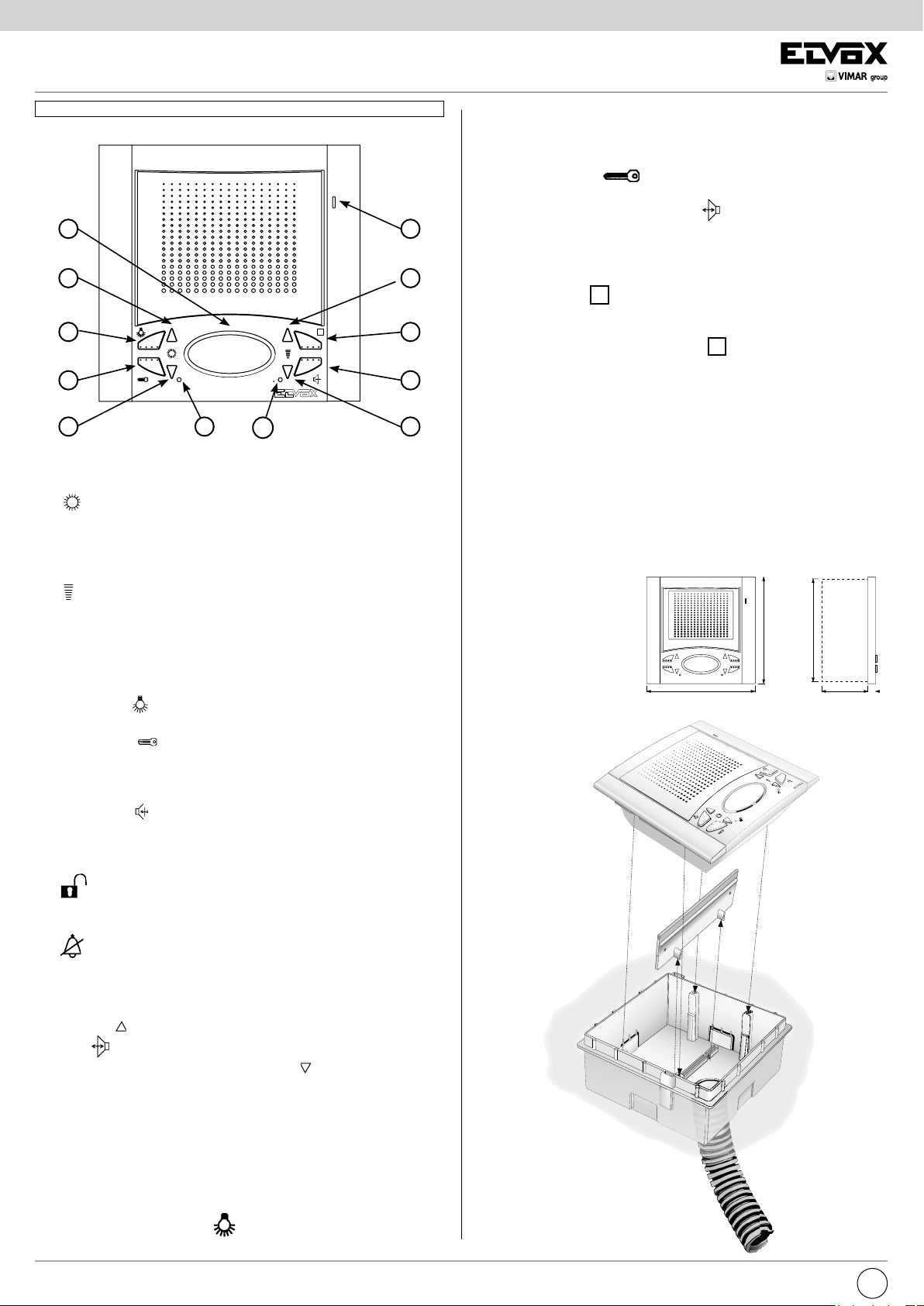
INSTALLAZIONE 6600/AU CON LE STAFFE Art. R660
- Praticare un foro nella parete in cartongesso di 120x120mm circa.
- Fissare le staffe Art. R660 al citofono 6600/AU.
- Fissare le staffe al citofono come indicato in figura, tenendo i cursori
allineati ai fianchi del citofono.
- Inserire il citofono all’interno della parete in cartongesso.
- Stringere le viti in modo da avvicinare i cursori alla parete di cartongesso.
Avvitando i cursori devono allinearsi ortogalmente al citofono.
- Inserire le mascherine laterali, facendo attenzione che quella con la fessura per il microfono, va inserita a destra.
Fig. 2A
INSTALLAZIONE 6700/AU
- Fissare la piastra di aggancio del citofono ad una altezza di 1,40m dal
pavimento al bordo inferiore
- Eseguire i collegamenti della morsettiera
- Inserire il citofono seguendo il senso delle frecce 1 e 2.
- Per togliere il citofono dalla piastra di aggancio, agire con un cacciavite
sulla linguetta di sicurezza ed estrarlo seguendo il senso delle frecce 3 e
4.
Montaggio da esterno
parete
141mm
Fig. 2B
139
mm
40mm
4
1
INSTALLAZIONE 660C
- Fissare la presa del citofono a parete e agganciare la borchia alla presa.
Montaggio da
tavolo
Fig. 2C
125
mm
2
REGOLE DI INSTALLAZIONE.
L’installazione deve essere effettuata con l’osservanza delle disposizioni regolanti l’installazione del materiale elettrico in vigore nel Paese dove i prodotti
sono installati.
CONFORMITÀ NORMATIVA.
Direttiva EMC
Norme EN 61000-6-1, EN 61000-6-3.
INFORMAZIONE AGLI UTENTI AI SENSI DELLA DIRETTIVA
2002/96 (RAEE)
Al ne di evitare danni all’ambiente e alla salute umana oltre che di
incorrere in sanzioni amministrative, l’apparecchiatura che riporta
questo simbolo dovrà essere smaltita separatamente dai riuti urbani ovvero
riconsegnata al distributore all’atto dell’acquisto di una nuova. La raccolta
dell’apparecchiatura contrassegnata con il simbolo del bidone barrato dovrà avvenire in conformità alle istruzioni emanate dagli enti territorialmente
preposti allo smaltimento dei riuti. Per maggiori informazioni contattare il
numero verde 800-862307.
3
IT
3
Page 4
6600
59mm
10mm
141 mm
125mm
125
mm
40mm
141mm
139
mm
The instruction manual is downloadable from the site www.vimar.com
C
D
F
G
D
PUSH-BUTTONS AND ADJUSTMENTS
B) Microphone.
C) Loudspeaker.
D)
When the interphone is not connected, the push-buttons can be used
Pair of push-buttons.
to select the tune for calls from a speech unit only. To programme the
tune: hold 1 of the 2 push-buttons down for at least 2 seconds, and
press the push-buttons again repeatedly to select the desired tune.
L
M
B
E
H
I
E
6: Power supply positive (minimum input voltage 15V D.C.)
7: Second auxiliary function
by the microswitch placed on the monitor rear side).
8: Call from entrance panel
9: Lock push-button
11: Landing call
12: Push-button for the audio activation
in “A” position)
13: Green LED supply voltage (18V D.C. (max) positive voltage imput)
NOTE: Interphone type 6600/AU dispose on the rear of a microswitch for
the switching of the “auxiliary (position A)/selfconnection (position B)” func-
tion of push-button
Monitor type Art. 660A/AU (6700/AU) dispose of a micro-switch on the bottom of the basis for the switching of the “auxiliary” function (lower position)
/self-start (upper position) of push-button
INSTALLATION 6600/AU
- Install the phone away from sources of light and heat.
- Flush-mount back box type 6149 in the wall at a height of approximately
1.4 m above the ground.
- Remove the plastic cross-piece from the back box
- Fix the phone to the back box with the 4 screws supplied (fig. 2).
- Fit the side panels, taking care that the panel with the slot for the micro-
phone is fitted on the right (fig. 2).
.
or self-start (its operation is controlled
(or selfconnection with switch
.
E)
Pair of push-buttons
1) While holding the “i” push-button down, press the “E” push-button to
increase or decrease the internal voice line volume.
2) To adjust ring-tone volume: without pressing the “I” push-button, hold
down 1 of the 2 push-buttons for at least 2 seconds, then press the
pushbuttons again repeatedly to increase, decrease or disable the ringtone volume.
F) Push-button
stair lights).
G) Push-button
H) Pushbutton
2nd lock). Enables the interphone to self-start without being called (the
function is optional according to the type of installation).
I) Pushbutton
the push-button down for conversation with the speech unit. Enables the
interphone to self-start without being called (the function is optional according to the type of installation).
L)
M) Call disabled signal: if the red LED lights up, this indicates that
PROGRAMMING OF THE CONVERSATION PRIVACY
The “Conversation privacy” function can be obtained by pressing both
push-buttons “ ” for 3 seconds at the same time; when the red led flashes
press the
be obtained as indicated above, but using both “ ” push-buttons.
Door open signal: if the green LED lights up, this indicates that
the door is open (the function is optional according to the type of installation).
the call is disabled (see point “E”).
: for activating 1st auxiliary service if connected (e.g.
: for door lock release.
: for activating 2nd auxiliary service if connected (e.g.
: after the call and/or switch-on of the interphone, hold
push-button. The “without conversation privacy” function can
Fig. 2
Flush-mounted
version
139
mm
136
TERMINALS FOR MONITOR TYPE 6600/AU, 660A/AU, 6700/AU
1: Interphone receiver
2: Interphone microphone
3: Common audio line
4: Button for auxiliary services
5: Power supply negative
(related to terminal 5)
4
EN
Page 5
6600
141mm
125mm
125
mm
Citofono serie 6600/AU
Installazione su parete
tipo cartongesso
Citofono serie 6600/AU
Installazione su parete
tipo cartongesso
141mm
125mm
INSTALLATION OF TYPE 6600/AU WITH BRACKETS TYPE R660
- Make a 120x120mm (nearly) hole in the plasterboard wall
- Fix the brackets type R660 to the phone 6600/AU
- Fix the bracket to the phone as indicated in figure, keeping the cursors
well aligned to the phone sides.
- Insert the phone inside the wall in plasterboard.
- Tighten the screws so as the cursors can get closer to the plasterboard
wall.
- By screwing, the cursors should get aligned orthogonally to the phone.
- Insert the side grids, paying attention that the one with the slot for the
microphone must be inserted on the right.
Fig. 2A
INSTALLATION OF TYPE 6700/AU
- Fix the phone fixing plate at 1,40m. from the ground level to the lower
border.
- Connect the terminal block.
- Insert the phone according to the 1 and 2 arrow direction
- To remove the phone from the plate hook, operate with a screw driver on
the security lock, and remove it according to the 3 and 4 arrow direction.
Surface wall-mounting
version
141mm
Fig. 2B
139
mm
40mm
4
1
INTSLLATION OF TYPE 660C
- Fix the phone support to the wall and hook the stud to the support.
Table version
125
mm
2
INSTALLATION RULES.
Installation should be carried out observing current installation regulations for
electrical systems in the Country where the products are installed.
3
EN
Fig. 2C
CONFORMITY.
EMC directive
Standards EN 61000-6-1, EN 61000-6-3.
INFORMATION FOR USERS UNDER DIRECTIVE 2002/96 (WEEE)
In order to avoid damage to the environment and human health as
well as any administrative sanctions, any appliance marked with this
symbol must be disposed of separately from municipal waste, that
is it must be reconsigned to the dealer upon purchase of a new one. Appliances marked with the crossed out wheelie bin symbol must be collected in
accordance with the instructions issued by the local authorities responsible
for waste disposal.
5
Page 6
6600
59mm
10mm
141 mm
125mm
125
mm
40mm
141mm
139
mm
Télécharger le manuel d’instructions sur le site www.vimar.com
C
D
F
G
D
BOUTONS-POUSSOIRS ET RÉGLAGES
B) Microphone.
C) Haut-parleur.
D)
Lorsque le poste d’appartement déclenché, les boutons-poussoirs per-
Paire de boutons-poussoirs
mettent de sélectionner la mélodie pour appel seulement à partir d’un
poste externe. Pour programmer la mélodie: appuyer pendant au moins
2 secondes sur l’un des 2 boutons-poussoirs, appuyer à plusieurs reprises sur les boutons-poussoirs pour sélectionner la mélodie voulue.
L
M
B
E
H
I
E
5: Negatif alimentation
6: Positif alimentation (tension minimal d’arrivée 15V c.c.)
7: Deuxième fonction auxiliaire
est géré par le microinterrupteur placé à l’arrière du moniteur)
8: Appel de la plaque de rue
9: Poussoir gâche
11: Appel de porte palière
12: Bouton-poussoir pour l’activation de la phonie
(ou auto-enclenchement avec commutateur en position “A”)
13: Alimentation LED verte (entrée “positif” alimentation max. 18V c.c.)
N.B. Le poste art. 6600/AU dispose à l’arrière d’un microinterrupteur pour
la commutation de la fonction “auxiliaire (position “A”)/auto-enclenchement
(position “B”) du bouton-poussoir
Le poste art. 660A/AU (6700/AU) dispose d’un microinterrupteur sur le fond
de la base pour la commutation de la fonction “auxiliaire” (position basse) /
autoenclenchement (position haute) du poussoir
INSTALLATION 6600/AU
- Installer le poste loin de toutes sources de lumière et de chaleur.
- Encastrer le boîtier art. 6149 au mur à environ 1,40 m du sol.
- Retirer la traverse en plastique du boîtier
- Fixer le poste au boîtier à l’aide des 4 vis fournies (fig 2).
- Installer les platines latérales en faisant attention que la platine prédispo-
sée avec l’ouverture micro soit placée à droite (fig. 2).
ou autoallumage (son fontionnement
.
.
E)
Paire de boutons-poussoirs
1) Avec le bouton-poussoir “I” activé, appuyer sur les touches “E” pour
augmenter ou diminuer le volume de la phonique interne.
2) Pour régler le volume de la sonnerie: ne pas appuyer sur le bou-
ton-poussoir “I” et appuyer pendant au moins 2 secondes sur un des
2 boutons-poussoirs, appuyer de nouveau à plusieurs reprises sur les
boutons-poussoirs pour augmenter, diminuer ou exclure le volume de
la sonnerie.
F) Bouton-poussoir
(par exemple, éclairage d’escaliers).
G) Bouton-poussoir
H) Bouton-poussoir
relié (par exemple, 2ème serrure).
Permet l’allumage automatique du poste sans avoir été appelé (cette
fonction est une option selon le type d’installation).
I) Bouton-poussoir
puyer continuellement sur le bouton-poussoir pour la conversation avec
le poste extérieur. Permet l’allumage automatique du poste sans avoir
été appelé (cette fonction est une option selon le type d’installation).
L)
M) Signalisation appel exclu: l’allumage de la signalisation (LED
PROGRAMMATION DU SECRET DE CONVERSATION
On obtient la fonction “ secret de conversation “ en appuyant simultanément
sur le deux boutons-poussoirs “ ” pour 3 secondes ; au clignotement de la
led rouge appuyer sur le bouton-poussoir
On obtient la fonction “ sans secret de conversation “ comme indiqué dessus, mais en utilisant le deux boutons-poussoirs “ ”.
Signalisation porte ouverte: l’allumage de la signalisation (LED
verte) indique que la porte est ouverte (cette fonction est une option
selon le type d’installation).
rouge) indique que l’appel est exclu (voir point “E”).
: pour l’activation du 1er service auxiliaire si relié
: pour l’ouverture de la serrure.
: pour l’activation du 2ème service auxiliaire si
: après l’appel et/ou l’allumage du poste, ap-
.
Fig. 2
Montage à
encastrement
139
mm
136
BORNES MONITEUR ART. 6600/AU, 660A/AU, 6700/AU
1: Écouteur de combiné
2: Microphone combiné
3: Commun circuit phonique
4: Poussoir pour services auxiliaires
(rélatif à la borne 5)
6
FR
Page 7

6600
Citofono serie 6600/AU
Installazione su parete
tipo cartongesso
Citofono serie 6600/AU
Installazione su parete
tipo cartongesso
141mm
125mm
141mm
125mm
125
mm
INSTALLATION DE L’ART. 6600/AU AVEC LES ÉTRIERS ART. R660
- Effectuer un trou dans la paroi en placo plâtre d’environ 120mm x 120mm
- Fixer les étriers Art. R660 au poste Art. 6600/AU.
- Fixer les étriers au poste comme indiqué dans la figure en tenant les
curseurs bien alignés aux côtés du moniteur.
- Insérer le poste dans la paroi en placo plâtre.
- Visser les vis de façon à approcher les curseurs à la paroi en placo plâtre.
- En vissant, les curseurs doivent s’aligner orthogonalement au moniteur.
- Insérer les masques latéraux en faisant attention a ce que celle avec
fente pour le microphone soit insérée à droite.
Fig. 2A
INSTALLATION ART. 6700/AU
- Fixer la plaque d’accrochage du poste à une hauteur d’environ 1,40m du
sol au bord inférieur.
- Effectuer les raccordements du bornier.
- Insérer le poste en suivant le sens des flèches 1 et 2.
- Pour enlever le moniteur de la plaque d’accrochage agir avec un tournevis
sur la languette de sécurité et l’extraire suivant le sens des flèches 3 et 4.
Version mural en saillie
141mm
Fig. 2B
139
mm
40mm
4
1
INSTALLATION ART. 660C
- Fixer le support du poste à paroi et accrocher la bossette au support.
Montage à
encastrement
125
mm
2
RÈGLES D’INSTALLATION.
L’installation doit être effectuée dans le respect des dispositions régulant
l’installation du matériel électrique en vigueur dans le Pays d’installation des
produits.
3
FR
Fig. 2C
CONFORMITÉ AUX NORMES.
Directive EMC
Normes EN 61000-6-1, EN 61000-6-3.
COMMUNICATION AUX UTILISATEURS CONFORMÉMENT À LA
DIRECTIVE 2002/96 (RAEE)
Pour protéger l’environnement et la santé des personnes et éviter
toute sanction administrative, l’appareil portant ce symbole ne devra
pas être éliminé avec les ordures ménagères mais devra être coné au distributeur lors de l’achat d’un nouveau modèle. La récolte de l’appareil portant
le symbole de la poubelle barrée devra avoir lieu conformément aux instructions divulguées par les organisms régionaux préposés à l’élimination des
déchets.
7
Page 8

6600
59mm
10mm
141 mm
125mm
125
mm
40mm
141mm
139
mm
Die Bedienungsanleitung ist auf der Website www.vimar.com zum Download verfügbar
C
D
F
G
D
L
M
B
E
H
I
E
TASTEN UND EINSTELLUNGEN
B) Mikrofon.
C) Lautsprecher.
D)
Tastenpaar
Bei ausgeschaltetem Monitor wird mit den Tasten die Melodie für den Ruf
von der Außenstation gewählt. Programmierung der Melodie: Eine der
beiden Tasten mind. zwei Sekunden gedrückt halten. Anschließend die
Melodie durch wiederholte Betätigung der Tasten wählen.
7: Zweite Zusatzfunktion oder Selbsteinschaltung (ihr Betrieb ist
vom auf der Rückseite befindlichen Umschalter gesteuert)
8: Ruf vom Klingeltableau
9: Türöffnertaste
11: Etagenruf
12: Taste für die Audio-Aktivierung
(oder Selbsteinschaltung mit
Schalter in “A” Stellung)
13: Stromversorgung für grüne LED (max +18V D.C.) “positive Linie”
Spannungsversorgungseingang)
HINWEIS: Die Freisprechstelle Art. 6600/AU (6700/AU) verfügt auf der
Rückseite über einen Umschalter für die Wahl der Zusatzfunktion (Stellung
“A”) oder Selbsteinschaltung (Stellung “B”)”-Funktion der Taste “
”.
Der Tischfreisprechstelle Art. 660A/AU hat diesen Umschalter auf der Unterseite des Geräts.
INSTALLATION 6600/AU
- Das Haustelefon fern von Licht- und Wärmequellen installieren.
- Das UP-Gehäuse Art. 6149 auf einer Höhe von etwa 1,40 m über dem
Boden an der Wand installieren.
- Die Plastikstrebe vom Gehäuse entfernen
- Das Haustelefon mit den 4 mitgelieferten Schrauben am Gehäuse befes-
tigen (Abb. 2).
- Die seitlichen Blenden einsetzen. Die Blende mit dem Schlitz für das Mi-
krofon muss rechts eingesetzt werden (Abb. 2).
E)
Tastenpaar.
1) Wird die Taste “I” gedrückt, kann währenddessen mit den Tasten “E”
die Lautstärke der internen Sprechleitung eingestellt werden.
2) Einstellung der Ruftonlautstärke: Die Taste “I” darf nicht gedrückt werden. Eine der beiden Tasten mindestens zwei Sekunden lang gedrückt
halten. Anschließend durch wiederholte Betätigung der Tasten die Lautstärke regulieren oder den Rufton ausschalten.
F) Taste
für erste Zusatzfunktion, insofern angeschlossen (z.B. Trep-
penhauslicht).
G) Türöffnertaste
H) Taste
für zweite Zusatzfunktion, insofern angeschlossen (z.B. 2.
Türöffner). Selbsteinschaltung des Haustelefon auch ohne Ruf (Funktion
auf Wunsch verfügbar und je nach Anlagentyp).
I) Taste
für Sprechverbindung mit der Außenstation nach einem Ruf
und/oder Haustelefoneinschaltung (während dem Gespräch die Taste
gedrückt halten). Selbsteinschaltung des Haustelefon auch ohne Ruf
(Funktion auf Wunsch verfügbar und je nach Anlagentyp)
L)
Anzeige “Türoffen”: Grüne LED-Anzeige für geöffnete Tür (Funk-
tion auf Wunsch verfügbar und je nach Anlagentyp).
M) Anzeige Rufabschaltung: Rote LED-Anzeige für Abschaltung des
Ruftons (s. Punkt “E”)
PROGRAMMIERUNG DER “ ABHÖRSPERRE “
Die “ABHÖRSPERRE”-Funktion wird ermöglicht wenn beide Tasten “ ” für
3 Sekunden gleichzeitig gedrückt werden; wenn die rote Led blinkt, die
Taste „
„ drücken. Die Abhörsperre kann durch Drücken beider Tasten “
” ausgeschaltet werden.
Abb. 2
Up-Montage
139
mm
136
KLEMMEN DER FREISPRECHSTELLEN ART. 6600/AU, 660A/AU,
6700/AU
1: Lautsprecher
2: Mikrofon
3: Gemeinsame, Sprechleitung
4: Taste für Zusatzfunktionen
(in Bezug auf Klemme 5)
5. Minus Versorgungsspannung
6: Plus Versorgungsspannung
(Mindest-Eingangsspannung 15 VDC)
8
DE
Page 9

6600
Citofono serie 6600/AU
Installazione su parete
tipo cartongesso
Citofono serie 6600/AU
Installazione su parete
tipo cartongesso
141mm
125mm
141mm
125mm
125
mm
INSTALLATION DES ART. 6600/AU MIT HALTERUNGEN ART. R660.
- Ein 120 x 120 mm (zirca) Loch in die Gipspappe-Wand durchführen.
- Die Halterungen Art. R660 an den Haustelefon befestigen.
- Die Halter durch Halten der Schieber auf der Haustelefon seiten vollkommen angereiht an den Haustelefon wie in Abb. gezeigt, befestigen.
- Den Haustelefon in die Gipspappe-Wand einstecken.
- Die Schrauben befestigen so dass die Schieber auf die Gipspappe nähen
können.
- Durch Anschrauben dürfen die Schieber orthogonal auf dem Haustelefon
angereiht werden
- Die Seitenmasken einstecken und beachten Sie dass die Maske mit der
Schlitze für das Mikrofon auf der Rechtenseite eingesteckt werden muss.
Abb. 2A
INSTALLATION DES ART. 6700/AU
- Die Befestigungsplatte des Haustelefon 1,40 m. in Höhe vom Boden bis
zu Unterkannt befestigen.
- Das Klemmenbrett anschliessen.
- Um den Haustelefon aus der Befestigungsplatte zu entfernen, mit einem
Schraubenzieher auf die Sicherheitfeder wirken und durch Folgen der
Federrichtung 3 und 4 ihn ausziehen.
Up-Wandmontage-Version
141mm
Abb. 2B
139
mm
40mm
4
1
INSTALLATION DES ART. 660C
- Den Wand-Haustelefonhalter befestigen und die Buchse an den Halter
anhaken.
Tischversion
125
mm
2
INSTALLATIONSVORSCHRIFTEN.
Die Installation hat gemäß den im jeweiligen Verwendungsland der Produkte
geltenden Vorschriften zur Installation elektrischer Ausrüstungen zu erfolgen.
3
DE
Fig. 2C
NORMKONFORMITÄT.
EMC-Richtlinie
Normen DIN EN 61000-6-1, EN 61000-6-3.
VERBRAUCHERINFORMATION GEMÄSS RICHTLINIE 2002/96
(WEEE)
Zum Schutz von Umwelt und Gesundheit, sowie um Bußgelder zu
vermeiden, muss das Gerät mit diesem Symbol getrennt vom Hausmüll entsorgt oder bei Kauf eines Neugeräts dem Händler zurückgegeben
werden. Die mit dem Symbol der durchgestrichenen Mülltonne gekennzeichneten Geräte müssen gemäß den Vorschriften der örtlichen Behörden, die
für die Müllentsorgung zuständig sind, gesammelt warden.
9
Page 10

6600
59mm
10mm
141 mm
125mm
125
mm
40mm
141mm
139
mm
El manual de instrucciones se puede descargar en la página web www.vimar.com
C
D
F
G
D
L
M
B
E
H
I
E
BOTÕES E REGULAÇÕES
B) Micrófono.
C) Altavoz.
D)
Par de pulsadores
Cuando o telefone não está inserido, los pulsadores permiten seleccio-
nar la melodía únicamente para la llamada desde el aparato externo.
Para seleccionar la melodía: mantener accionado, durante 2 segundos
como mínimo, uno de los 2 pulsadores y accionar repetidamente los
pulsadores hasta encontrar la melodía deseada.
7: Segunda función auxiliar o autoencendido (su funcionamiento
viene controlado por el microinterruptor que se encuentra detrás del
monitor)
8: Llamada desde la placa externa
9: Pulsador para la apertura de la cerradura
11: Llamada desde fuera de la puerta
12: Pulsador para la activación de la fónica
mutador en posición “A”)
(o autoinserción con con-
13: Alimentación del LED verde (entrada positivo alimentación máx 18V
c.c.)
V: Para instalaciones con cable coaxial, entrada para la conexión del cable
vídeo de 75 Ohm.
M: Masa correspondiente a los bornes V.
N.B. El monitor Art. 6600/AU (6700/AU) dispone en la parte posterior de un
microinterruptor para la conmutación de la función “auxiliar (posición “A”)/
autoinserción posición “B”)” del pulsador
.
El monitor Art. 660A/AU dispone de un microinterruptor que se encuentra
en el fondo de la base para la conmutación de la función “auxiliar” (posición
en bajo)/autoencendimento (posición en alto) del pulsador
.
INSTALACIÓN 6600/AU
- Instalar el teléfono lejos de fuentes luminosas y de calor.
- Empotrar la caja art. 6149 en la pared, a aproximadamente 1,40 m del
suelo.
- Quitar el travesaño de plástico de la caja.
- Fijar el teléfono a la caja con los 4 tornillos suministrados (fig. 2).
- Montar las máscaras laterales teniendo en cuenta que la máscara con
la ranura para el microteléfono tiene que ir a la derecha (fig. 2).
E)
Par de pulsadores
1) Con el pulsador “I” accionado, accionar los pulsadores “E” para au-
mentar o disminuir el volumen de la línea fónica interna.
2) Para regular el volumen del timbre: no accionar el pulsador “I” y man-
tener accionado, durante 2 segundos como mínimo, uno de los 2 pulsadores, accionar repetidamente los pulsadores para aumentar, disminuir
o excluir el volumen del timbre.
F) Pulsador
: para la activación del 1er servicio auxiliar si se ha conec-
tado (por ejemplo, luces de la escalera).
G) Pulsador
H) Pulsador
: para la apertura de la cerradura.
: para la activación del 2º servicio auxiliar si se ha conec-
tado (por ejemplo, 2ª cerradura).
Permite el autoencendido del teléfono sin que se haya producido una
llamada (la función es opcional en relación con el tipo de instalación).
I) Pulsador
: tras la llamada y/o el encendido del teléfono, mantener
accionado el pulsador para la conversación con el aparato externo.
Permite el autoencendido del teléfono sin que se haya producido una
llamada (la función es opcional en relación con el tipo de instalación).
L) Señalización de puerta abierta
: el encendido de la señalización
(LED verde) indica que la puerta está abierta (la función es opcional en
relación con el tipo de instalación).
M) Señalización de llamada excluida : el encendido de la señaliza-
ción (LED rojo) indica que la llamada se encuentra excluida (véase
punto “E”).
PROGRAMACIÓN DEL SECRETO DE CONVERSACIÓN
La función “secreto de conversación “ se obtiene manteniendo presados
simultáneamente los dos pulsadores “ ” por 3 segundos; al relampagueo
del led rojo pulsar el pulsador
se obtiene como indicado arriba, pero utilizando los dos pulsadores “
. La función “sin secreto de conversación”
”.
Versión de empotre
Fig. 2
139
mm
136
BORNES DEL MONITOR ART. 6600/AU, 660A/AU, 6700/AU
1: Receptor del auricular
2: Micrófono del auricular
3: Común de la línea fónica
4: Pulsador para servicios auxiliares
5: Negativo de la alimentación
(relativo al borne 5)
6: Positivo de la alimentación (tensión mínima de llegada 15 Vcc)
10
ES
Page 11

6600
141mm
125mm
125
mm
Citofono serie 6600/AU
Installazione su parete
tipo cartongesso
Citofono serie 6600/AU
Installazione su parete
tipo cartongesso
141mm
125mm
INSTALACIÓN DEL ART. 6600/AU CON LOS SUPORTES ART. R660,
- Efectuar un orificio en la pared en cartón piedra de cerca 120x120mm
- Fijar los soportes Art. R660 al teléfono Art. 6600/AU.
- Fijar los soportes al teléfono como indica la figura, manteniendo los cursores alineados a los lados del teléfono.
- Insertar el teléfono en la pared en cartón piedra.
- Fijar los tornillos de manera que los cursores se puedan acercar a la
pared de cartón piedra.
- Entornillando, los cursores deben alinearse ortogonalmente al teléfono.
- Insertar las máscaras laterales prestando atención que aquella con la
apertura para el micrófono debe ser insertada a la derecha.
INSTALACIÓN DEL ART. 6700/AU
- Fijar la placa de enganche del teléfono a una altura de 1,40m desde el
piso al borde inferior.
- Efectuar las conexiones de la regleta de conexiones .
- Insertar el teléfono siguiendo el sentido de las flechas 1 y 2.
- Para quitar el teléfono de la plancha de enganche, actuar con un destornilladoer sobre la lengüeta de seguridad y extraerlo siguiendo el sentido
de las flechas 3 y 4.
Versión de sobremesa
141mm
Fig. 2B
139
mm
40mm
4
1
Fig. 2A
INSTALACIÓN DEL ART. 660C
- Fijar el soporte del teléfono a la pared y enganchar la tachuela al soporte.
Versión de
empotre
125
mm
2
NORMAS DE INSTALACIÓN.
El aparato se ha de instalar en conformidad con las disposiciones sobre material eléctrico vigentes en el País.
3
ES
Fig. 2C
CONFORMIDAD NORMATIVA.
Directiva EMC
Normas EN 61000-6-1 y EN 61000-6-3.
INFORMACIÓN A LOS USUARIOS DE CONFORMIDAD CON LA
DIRECTIVA 2002/96 (RAEE)
Para evitar perjudicar el medio ambiente y la salud de las personas,
así como posibles sanciones administrativas, el aparato marcado
con este símbolo no deberá eliminarse junto con los residuos urbanos y podrá entregarse en la tienda al comprar uno nuevo. La recogida del aparato
marcado con el símbolo del contendedor de basura tachado deberá realizarse de conformidad con las instrucciones emitidas por las entidades encargadas de la eliminación de los residuos a nivel local.
11
Page 12

6600
59mm
10mm
141 mm
125mm
125
mm
40mm
141mm
139
mm
É possível descarregar o manual de instruções no site www.vimar.com
C
D
F
G
D
L
M
B
E
H
I
E
PULSADORES Y REGULACIONES
B) Micrófono
C) Altifalante.
D)
Par de botões
Quando el telefono no está insertado os botões permitem a seleção
da melodía só para a chamada do posto externo. Para programar a
melodía: mantener premido pelo menos 2 segundos um dos 2 botões,
voltar a premir repetidamente os botões para selecionar a melodía interesada.
7: Segunda função auxiliar ou autoacendimento (o suo funciona-
mento é gerido pelo microinterruptor que fica detrás do monitor).
8: Chamada da botoneira externa
9: Botão do trinco
11: Chamada do patamar
12: Botão para a activação da fónica
(ou autoinserção com comutador
em posição “A”)
13: Alimentação LED verde (entrada positivo alimentação máx 18V c.c.)
V: Para instalações com cabo coaxial, entrada para a ligação do cabo
vídeo a 75 Ohm.
M: Massa referente aos bornes V
N.B. O monitor art. 6600/AU (6700/AU) dospõe na parte posterior dum
microinterruptor para a comutação da função “auxiliar (posição “A”)/autoin-
serção (posição “B”)” do botão
.
El monitor Art. 660A/AU dispõe dum microinterruptor no fundo da base para
a comutação da função “auxiliar” (posição para baixo)/autoacendimento
(posição para arriba) do botão
.
INSTALAÇÃO 6600/AU
- Instalar o telefone afastado de fontes luminosas e de calor.
- Embeber a caixa Art. 6149 na parede a uma altura aprox. de 1,40 m do
pavimento.
- Retirar o travessa, em plástico, da caixa
- Fixar o telefone à caixa com os 4 parafusos fornecidos (fig 2).
- Inserir as máscaras laterais, tendo atenção para que a abertura para o
microfone, seja inserida à direita (fig. 2).
E)
Par de botões
1) Com o botão « i » premido, premir o botaõ “E” para aumentar o diminuir
o voume da fónica interna.
2) Para regular o volume da campainha: não premir o botão “I” e manter
premido pelo menos 2 segundos um dos dois botões , voltar a premir
repetidamente os botões para aumentar ou diminuir ou excluir o volume
da campainha.
F) Botão
: para a activação do 1° serviço auxiliar, se ligado (por exem-
plo: luzes da escada).
G) Botão
H) Botão
: para abertura do trinco
: para a activação do 2° serviço auxiliar, se ligado (por exem-
plo: 2° trinco). Permite o autoacendimento do telefone sem ter sido
chamado (a função é opcional em relação ao tipo de instalação).
Botão: para a chamada e/ou o acendimento do telefone manter
I)
premido o botão para a conversação com o posto externo. Permite o
autoacendimento do telefone sem ter sido chamado (a função é opcional em relação ao tipo de instalação).
L)
Sinalização porta aberta: acendimento da sinalização (LED
verde) indica que a porta está aberta (a função é opcional em relação
ao tipo de instalação).
M)
Sinalização chamada excluida: o acendimento da sinalização
(LED vermelho) indica que a chamada é excluida (ver ponto “E”).
PROGRAMAÇÃO DO SEGREDO DE CONVERSAÇÃO
A função “sem segredo de conversação” obtem-se tendo premidos simultâneamente os dois botões “ ” por 3 segundos; ao cintilar do led vermelho
Versão de embeber
Fig. 2
139
mm
136
premir o botão
. A função “sem segredo de conversação” obtem-se
como indicado arriba, mas utilizando os dois botões “ ”.
BORNES MONITOR ART. 6600/AU, 660A/AU, 6700/AU
1: Altifalante
2: Microfone tipo corneta
3: Linha comum audio
4: Botão para serviços auxiliares
(relativo ao terminal 5)
5: Negativo alimentação
6: Positivo alimentação (tensão mínima na chegada 15V c.c.)
12
PT
Page 13

6600
Citofono serie 6600/AU
Installazione su parete
tipo cartongesso
Citofono serie 6600/AU
Installazione su parete
tipo cartongesso
141mm
125mm
141mm
125mm
125
mm
INSTALAÇÃO DO 6600/AU COM OS SUPORTES Art. R660
- Efectuar um furo na parede, em gesso cartonado, de aprox. 120x120
mm.
- Fixar o suporte Art. R660 ao telefone 6600/AU.
- Fixar os suportes ao telefone como indica a figura, tendo os cursores
alinhados aos lados do telefone.
- Inserir o telefone na parede em cartão gessado.
- Parafusar os parafusos de modo a que os cursores se acerquem à pa-
rede em cartão gessado.
- Parafusando, os cursores devem-se alinhar ortogonalmente ao telefone.
- Inserir as máscaras laterais, tendo cuidado para que a que tem uma
ranhura para o microfone, fique inserida à direita conforme o indicado na
figura.
Fig. 2A
INSTALAÇÃO DO ART. 6700/AU
- Fixar a placa de encaixe do telefone a uma altura de 1,40 m entre o pavimento e o bordo inferior.
- Efectuar as ligações da régua de bornes.
- Inserir o telefone seguindo o sentido das setas 1 e 2.
- Para retirar o telefone da placa de encaixe, aplicar uma chave de parafusos na lingueta de segurança e extraí-lo seguindo o sentido das setas 3
e 4.
Versão montagem
saliente
141mm
Fig. 2B
139
mm
40mm
4
1
INSTALAÇÃO DO 660C
- Fixar a placa do telefone na parede e enfiar a ficha na tomada.
Versão de mesa
125
mm
2
REGRAS DE INSTALAÇÃO
A instalacao deve ser efectuada de acordo com as disposicoes que regulam
a instalacao de material electrico, vigentes no Pais em que os produtos sao
instalados.
3
PT
Fig. 2C
CUMPRIMENTO DE REGULAMENTAÇÃO
Directiva EMC
Normas EN 61000-6-1, EN 61000-6-3.
INFORMAÇÃO AOS UTILIZADORES NOS TERMOS DA DIRECTIVA 2002/96 (REEE)
Para evitar danos ao meio ambiente e à saúde humana, e evitar
incorrer em sanções administrativas, o equipamento que apresenta
este símbolo deverá ser eliminado separatamente dos resíduos urbanos ou
entregue ao distribuidor aquando da aquisição de um novo. A recolha do
equipamento assinalado com o símbolo do contentor de lixo barrado com
uma cruz deverá ser feita de acordo com as instruções fornecidas pelas
entidades territorialmente previstas para a eliminação de resíduos.
13
Page 14

6600
Legenda per schemi di collegamento - Legenda for wiring diagram - Légende pour schémas de raccordement
Beschriftung für Schalpläne - Leyenda para esquemas de conexionado - Legenda para esquemas de conexionado
A- Targa per videocitofono
Serie 1200, 1300, 8000, 8100, PATAVIUM,
portalettere 2550/301-302 e casellario 2561
B- Pulsante supplementare serratura
C- Serratura elettrica 12V~
D- Telecamera con posto esterno
Art. 559B, 559C, 570C+930A
L1- Modulo LED targa
(10 moduli LED max.)
30 moduli LED con Art. M832
40 moduli LED con Art. 0832/030
A- Videotürstelle Serie 1200, 1300, 8000, 8100,
PATAVIUM, Briefkasten 2550/301-302 und
2561
B- Zusätzliche Türöffnertaste
C - Elektrischer Türöffner 12 V~
D- Kamera mit Sprechstelle
Art. 559B, 559C, 570C+930A
L1- LED-Modul für Klingeltableau
(10 Modul LED max.)
30 Modul LED mit Art. M832
40 Modul LED mit Art. 0832/030
Posizionare il microinterruttore su senza
segreto di conversazione. Il microinterruttore
è posto sul retro del monitor.
The monitors have a microswitch on the back,
set it to “without conversation privacy”.
Positionner le micro-interrupteur sur la fonction
excluant le secret de conversation. Le microinterrupteur est situé à l’arrière du moniteur.
Den Umschalter auf der Monitorrückseite auf
„ohne Mithörsperre” schalten.
Colocar el microinterruptor en la función sin
conversación privada. El microinterruptor está
en la parte posterior del monitor.
Colocar o microinterruptor em “sem segredo
de conversação”. O microinterruptor situa-se
na parte de trás do monitor.
A- Video entrance panel
1200, 1300, 8000, 8100, PATAVIUM and letter
box 2550/301-302, 2561 series
B- Additional door lock button
C- 12V~ electric lock
D- Camera with speech unit
type 559B, 559C, 570C+930A
L1- Led module for entrance panel
(10 module LED max.)
30 module LED con Art. M832
40 module LED con Art. 0832/030
A- Placa para vídeo-portero de las series
1200, 1300, 8000, 8100, PATAVIUM, buzón
2550/301-302 y 2561
B- Pulsador suplementario para cerradura
C- Cerradura eléctrica 12 V~
D- Cámara con aparato externo Art. 559B, 559C,
570C+930A
L1- Módulo Led para placa
(10 módules LED max.)
30 módules LED con Art. M832
40 módules LED con Art. 0832/030
La funzione “SEGRETO DI CONVERSAZIONE” è normalmente
disattivata. Per attivare o disattivare la funzione vedere
programmazione del segreto.
The “CONVERSATION PRIVACY” function is normally
deactivated. To activate or deactivate the function see
conversation privacy programming.
La function “SECRET DE CONVERSATION” est normalement
désactivée. Pour activer ou désactiver la fonction voir la
programmation du secret de conversation.
Die « ABHÖRSPERRE » ist normalerweise deaktiviert. Um die
Funktion zu aktivieren oder deaktivieren siehe die Anleitung zur
Programmierung der Abörsperre.
La función „SECRETO DE CONVERSACIÓN” es normalmente
desactivada. Para activar o desactivar la función ver
programación del secreto de conversación.
A função “SEGREDO DE CONVERSAÇÃO” é normalmente
desactivada. Para activar ou desactivar a função ver a
programação do segredo de conversação.
A- Plaque de rue pour portier vidéo
Série 1200, 1300, 8000, 8100, PATAVIUM,
B- Poussoir supplémentaire gâche
C- Gâche électrique 12V~
D- Caméra avec poste externe
Art. 559B, 559C, 570C+930A
L1- Module LED pour plaque de rue
(10 module LED max.)
30 module LED con Art. M832
40 module LED con Art. 0832/030
A- Botoneira para vídeo-porteiro
Série 1200, 1300, 8000, 8100, PATAVIUM e
B- Botão suplementar do trinco
C- Trinco eléctrico 12V~
D- Telecâmara com posto externo
Art. 559B, 559C, 570C+930A
L1- Módulo LED para botoneira
(10 módules LED max.)
30 módules LED con Art. M832
40 módules LED con Art. 0832/030
boîte aux lettres 2550/301-302 et 2561
caixa de correio 2550/301-302 e 2561
N.B.: In caso di ronzio sulla fonica spostare
il commutatore “A-B” situato sotto il
coperchio in posizione “A”.
N.B.: In the event of buzzing on the audio
line, move the switching module “A-B”
located under the cover to position “A”.
N.B.: En cas de bourdonnement sur la ligne
phonique, basculer le commutateur “A-B”
situé sous le couvercle, sur la position “A”.
HINWEIS: Falls in der Sprechleitung ein
Brummton zu hören ist, den Umschalter
„A-B” unter dem Deckel auf „A” verstellen.
N.B.: en caso de perturbaciones en la
conexión fónica, mover el conmutador “A-B”
situado debajo de la tapa a la posición “A”.
N.B.: No caso de ruído no audio mudar
o comutador “A-B”, situato por baixo da
cobertura, na posição “A”.
14
ITENFRDEESPT
Page 15

6600
C
IMPIANTO VIDEOCITOFONO MONO E PLURIFAMILIARE “SOUND SYSTEM” CON ALIMENTATORE ART. 6680 SENZA SEGRETO DI CONVERSAZIONE
“SOUND SYSTEM” SINGLE AND MULTIPLE RESIDENCE VIDEO DOOR ENTRY SYSTEM WITH POWER SUPPLY TYPE 6680 AND WITHOUT CONVERSATION
INSTALLATION PORTIER VIDÉO MONO ET PLURIFAMILIAL “SOUND SYSTEM” AVEC ALIMENTETION ART. 6680 SANS SECRET DE CONVERSATION
VIDEOTÜRSPRECHANLAGE FÜR EIN- UND MEHRFAMILIENHÄUSER „SOUND SYSTEM” MIT NETZGERÄT ART. 6680 OHNE MITHÖRSPERRE
INSTALACIÓN DE VÍDEO-PORTERO UNI Y PLURIFAMILIAR “SOUND SYSTEM” CON ALIMENTADOR ART. 6680 Y SIN CONVERSACIÓN PRIVADA
INSTALAÇÃO VIDEO-PORTEIRO MONO E PLURIFAMILIAR “SOUND SYSTEM” COM ALIMENTADOR ART. 6680 SEM SEGREDO DE CONVERSAÇÃO
PRIVACY
Monitor colori
Colour monitor
Moniteur couleurs
Farbmonitor
Monitor a colores
Monitor cores
Art. 6023 +
Art. 6200 +
Art. 6145
Monitor colori
Colour monitor
Moniteur couleurs
Farbmonitor
Monitor a colores
Monitor cores
Art. 6341
Art. 6351
Monitor colori
Colour monitor
Moniteur couleurs
Farbmonitor
Monitor a colores
Monitor cores
Art. 6620
Art. 662A
Art. 6720
6S5321V
V1
*
M
V2
M
V3
+A
CN1
+
-
+D
CH
Montante monitor
Monitor cable riser
Montant moniteur
Monitorsteigleitung
Coluna montante de monitores
*
Nell’ultimo monitor inserire tra i morsetti V2-M la
resistenza di 75 Ohm fornita in dotazione.
Connect 75 Ohm resistor (supplied) to the last monitor,
between terminals V2-M.
Raccorder dans le dernier moniteur la résistance de
75 Ohms fournie entre les bornes V2-M.
Beim letzten Monitor zwischen Klemmen V2-M den
mitgelieferten 75 Ohm Abschlusswiderstand montieren.
Montar la resistencia de 75 Ohm suministrada de serie
CN1 CN2
7
AU
1
2
3
5
6E
6
C
6P
A
6S
V2
V1
M
V3
13
12
11
10
9
8
7
6
5
4
3
2
1
Cavo - Cable
Câble - Kabel
Cable - Cabo
Art. 61/001
Art. 61/003
Citofono
Interphone
Poste
Freisprechstelle
entre los bornes V2-M del último monitor.
No último monitor inserir a resistência de 75 Ohm
fornecida entre os bornes V2-M.
Teléfono
M
V
13
12
11
10
9
8
7
6
5
4
3
2
1
CHCH CH 6S53
CH
21V
Telefone
Art. 6600/AU
13
12
Art. 660A/AU
11
Art. 6700/AU
10
9
8
7
6
5
4
3
2
1
RETE-MAINS
RÉSEAU-NETZ
RED-REDE
PRI
V1M1 3AUM2V21C2 2
A
Art. 6680
B
+-S76-8AM+T 015 S1 C1
Alimentatore
Power supply
Alimentation
Netzgerät
Alimentador
Cavo - Cable
Câble - Kabel
Cable - Cabo
Art. 0061/001
Art. 0061/003
L1
A
ELVOX
PTESDEFRENIT
3
4
6
7
8
CT
+T
D
V
M
B
N° vc5165
15
Page 16

6600
SCHEMA DI COLLEGAMENTO PORTIERE ELETTRICO CON SISTEMA DI CHIA MA TA “SOUND SYSTEM”
WIRING DIAGRAM OF ELECTRIC DOOR OPENER WITH “SOUND SYSTEM” CALL
SCHÉMA DES CONNEXIONS POUR PORTIER ÉLECTRIQUE AVEC APPEL “SOUND SYSTEM”
SHALTPLAN FÜR TÜRSPRECHANLAGE MIT “SOUND SYSTEM” RUF
ESQUEMA DE CONEXIONADO PORTERO ELÉCTRICO CON SISTEMA DE LLAMADA “SOUND SYSTEM”
ESQUEMA DE LIGAÇÃO DO PORTERO ELÉCTRICO COM CHAMADA “SOUND SYSTEM”
Sezione conduttori - Conductor section
Sections des conducteurs-Leiterqueschnitt
Secciones conductores-Secção condutores
Conduttori-Conductors Ø fino a 50m-Ø up to 50m Ø fino a 100m-Ø up to 100m Ø fino a 200m-Ø up to 200m
Conductors-Leitungslänge Ø jusqu’à 50m-Ø bis 50m Ø jusqu’à 100m.-Ø bis 100m Ø jusqu’à 200m.-Ø bis 200m
Conductores-Condutores Øhasta 50m - até 50m Ø hasta 100m - até 100m Ø hasta 200m - Ø até 200m
Comune e serratura
Common and lock
Commun et gâche
Gemeinsame und Türöffner 0,5 mm
Común y cerradura
Commun e trinco
Altri-Others-Autres
Andere-Otros-Outros 0,25 mm
Citofono - Phone
Poste - Freisprechstelle
Teléfono - Telefone
Art. 6600/AU
Art. 660A/AU
Art. 6700/AU
Citofono - Phone
Poste - Freisprechstelle
Teléfono - Telefone
Art. 8875
2
0,75 mm2 1,5 mm
2
0,5 mm2 1 mm2
Rete-Mains
Réseau-Netz
Alimentatore
Power supply
Alimentation
Netzgerät
Alimentador
Art. 6582
13
12
11
10
F
9
8
7
6
5
4
3
2
1
B
1
2
3
4/5
6
7
8
Red-Rede
PRI
+U
-+IBAC
Rete-Mains
Réseau-Netz
Red-Rede
2
PRI
Alimentatore
Power supply
Alimentation
Netzgerät
Alimentador Art. 0931
3-D12
C2 768 OC1 15 AS
Relè
Relay
Relais
Art. 0170/001
1234
B
A- Targa con posto esterno
Entrance panel
Plaque de rue avec poste externe
Klingeltableau mit Außenstelle
Placa con aparato externo
Botoneira com posto externo
serie-série Patavium
1200 - 1300 - 3300 - 8000 - 8100
B- Pulsante supplementare ser ra tu ra
Additional push-button for lock
Poussoir supplémentaire gâche
zusätzliche Türöffnertaste
Pulsador suplementario cerradura
Botão suplementar de trinco
C- Serratura elettrica
Electric lock
Gâche électrique
Elektrischer Türöffner
Cerradura eléctrica
Trinco eléctrico 12V~
D- Posto esterno - Outdoor unit
Poste externe - Außenstelle
Aparato externo - Posto esterno
Art. 0930/000.04 - 930A
L1- Modulo LED targa
5
Led module for entrance panel
LED-Modul für Klingeltableau
Module LED pour plaque de rue
Módulo Led para placa
Módulo LED para botoneira
(10 LED max.)
30 LED con/with Art. M832
40 LED con/with Art. 0832/030
A
L1
3
4
5
D
6
7
8
R
C
CA6P
Citofono - Phone
Poste - Freisprechstelle
Teléfono - Telefone
Art. 6200
DISEGNO N° C5175R2
16
F
7
AU
1
2
3
5
6E
6
6S
F
12
3
C2 S
N.B.
IN CASO DI RONZIO SULLA FONICA SPO STA RE NELL’ALI MEN TA TO RE IL FILO COL LE GA TO ALLA SER RATU RA DAL MORSETTO 15 AL MORSETTO AS.
IN CASE OF NOISE IN THE AUDIO MOVE, IN THE
POWER SUPPLY, THE WIRE CONNECTED ON THE
DOOR LOCK TERMINAL N. 15 TO TERMINAL AS.
S’IL Y A DE BROUILLARD DANS LA PHONIQUE DEPLACER DANS L’ALIMENTATION LE FIL, CONNECTÉ
Á LA GÂCHE, DE LA BORNE 15 Á LA BORNE AS.
SOLLTE ES TROTZ ORDNUNGSGEMÄSSER VERDRAHTUNG ZU EINEM BRUMMTON KOMMEN, BITTE
DIE TÜRÖFFNER-ADER GETRENNT LEGEN UND AN
DIE KLEMME AS ANSCHLIESSEN.
SI SE OYE EN EL AUDIO UN RUIDO, DESPLAZAR EN
CH
EL ALIMENTADOR EL HILO CONECTADO A LA CERRADURA DEL BORNE 15 AL BORNE AS.
NO CASO DE ZUMBIDO NO AUDIO, DESLOCAR NO
ALIMENTADOR O FIO LIGADO NO TRINCO DO SHUNT
15 AO AS.
La funzione “SEGRETO DI CONVERSAZIONE” è normalmente disattivata. Per attivare o disattivare la funzione
vedere programmazione del segreto.
The “CONVERSATION PRIVACY” function is normally
deactivated. To activate or deactivate the function see
conversation privacy programming.
La function “SECRET DE CONVERSATION” est normalement désactivée. Pour activer ou désactiver la fonction
voir la programmation du secret de conversation.
Die « ABHÖRSPERRE » ist normalerweise deaktiviert.
Um die Funktion zu aktivieren oder deaktivieren siehe die
Anleitung zur Programmierung der Abhörsperre.
La función “SECRETO DE CONVERSACIÓN” es normalmente desactivada. Para activar o desactivar la función
ver programación del secreto de conversación.
A função “SEGREDO DE CONVERSAÇÃO” é normalmente desactivada. Para activar ou desactivar a função
ver a programação do segredo de conversação.
ITENFRDEESPT
Page 17

6600
2
6S
6E
6P
6
3
5
7
AU
1
CN1
V1
10
8
6
7
9
V3
13
M
11
12
V2
123
-
S678-+T AM 15
O
S1
+
C1
PRI
M1 V1 V2 M2 AU C2
A
B
CN2
A
M1 V2V1 M2 C2BAU 1
PRI
+32-S6 +T87-AM 15 0C1S1
V
M
123
-
S678-+T AM 15OS1+C1
A
B
VARIANTE - VERSION - SONDERSCHALTUNG - VARIACIÓN 1
Schema di collegamento del pulsante autoinserimento del citofono
Wiring diagram for selfconnection of interphone
Schéma de raccordement du bouton-poussoir
Anschluss der Taste für Monitor-Selbsteinschaltung
Esquema de conexión del pulsador de autoinserción del teléfono
Ligação do botão de autoinserção do telefone
E’ possibile attivare l’impianto dal citofono, utilizzando il pulsante con il simbolo “ ”
collegato al morsetto 12 come illustrato nello schema.
It is possible to activate the system from the interphone, using the push-button with the
symbol “ ”, by connecting it to terminal 12 as shown in the diagram.
Il est possibile d’activer l’installation depuis le poste en utilisant le bouton-poussoir
avec le symbole “
Es ist möglich, die Türsprechanlage am Freisprechgerät zu aktivieren. Hierfür ist die
Taste mit dem Symbol „
Es posible activar el equipo desde el teléfono, mediante el pulsador con el símbolo “
” hay que conectarlo al borne 12 como se ilustra en el esquema.
É possível activar a instalação do telefone, utilizando o botão com o símbolo “
ligando-o ao terminal 12 como se mostra no esquema.
” en le raccordant à la borne 12 comme indiqué sur le schéma.
” laut Schaltplan an Klemme 12 anzuschließen.
auto-enclenchement
interphone
”
RETE-MAINS
RÉSEAU-NETZ
RED-REDE
PRI
Citofono
Phone
Poste
Freisprechstelle
Teléfono
Telefone
Art. 6600/AU
Art. 660A/AU
Art. 6700/AU
Alimentatore
Power supply
Alimentation
Netzgerät
Alimentador
A
B
13
12
11
10
9
8
7
6
5
4
3
2
1
Art. 6680
S1M1 +AUV1 V2 M2 2C2 13-S678AM+T-150
C1
VARIANTE - VERSION - SONDERSCHALTUNG - VARIACIÓN 2
Schema di collegamento del pulsante chiamata fuoriporta con alimentatore art. 6680.
Wiring diagram for landing call button with power supply art. 6680.
Schéma de raccordement du bouton-poussoir appel de porte palière avec alimentation art.
6680
.
Anschluss der Etagenruftaste mit Netzgerät Art. 6680.
Esquema de conexión del pulsador de llamada desde fuera de la puerta con alimentacion art. 6680.
Ligação botão chamada do patamar com alimentador art. 6680.
Azionando il pulsante fuoriporta il citofono suona con
tonalità differente da quello ottenuto con la chiamata
dalla targa esterna.
When the landing call push-button is pressed, the
interphone sounds with a different tone from the
tone generated by a call from the entrance panel.
En actionnant le bouton-poussoir de la porte palière, le
poste produit une tonalité différente de celle obtenue en
appelant à partir de la plaque de rue.
Beim Etagenruf läutet die Freisprechstelle mit einem
anderen Ton als bei einem Ruf vom Klingeltableau.
Al accionar el pulsador de llamada desde fuera de la
puerta, el teléfono suena con una tonalidad diferente
a la obtenida con la llamada desde la placa externa.
Accionando o botão do patamar, o telefone toca com
um timbre diferente do obtido com a chamada da
botoneira externa.
A- Pulsante per chiamata fuoriporta
Landing call push-button
Poussoir appel de porte palière
Etagenruftaste
Pulsador de llamada desde fuera de la puerta
Botão para chamada do patamar
Citofono
Phone
Freisprechstelle
Teléfono
Telefone
Art. 6600/AU
Art. 660A/AU
Art. 6700/AU
Poste
5
4
3
2
1
RETE-MAINS
RÉSEAU-NETZ
RED-REDE
PRI
M
V
13
12
11
10
9
8
7
6
5
4
3
2
1
A
Alimentatore
Power supply
Alimentation
Netzgerät
Alimentador
A
B
Art. 6680
S1 C10AM 15+T8-76S+32-AU C2V2 M2V1M1 1
PTESDEFRENIT
17
Page 18

6600
21C23- 715C1806AS
PRI
7
1
4
2
3
6
5
10
9
8
12
11
13
A
71
806A
A
VARIANTE - VERSION - SONDERSCHALTUNG - VARIACIÓN 3
Schema di collegamento del pulsante chiamata fuoriporta con alimentatore art. 0931.
Wiring diagram for landing call button with power supply art. 0931.
Schéma de raccordement du bouton-poussoir appel de porte palière avec alimentation art. 0931.
Anschluss der Etagenruftaste mit Netzgerät Art. 0931.
Esquema de conexión del pulsador de llamada desde fuera de la puerta con alimentacion art. 0931.
Ligação botão chamada do patamar com alimentador art. 0931.
Azionando il pulsante fuoriporta il citofono suona con
tonalità differente da quello ottenuto con la chiamata
dalla targa esterna.
When the landing call push-button is pressed, the
interphone sounds with a different tone from the
tone generated by a call from the entrance panel.
En actionnant le bouton-poussoir de la porte palière,
le poste produit une tonalité différente de celle obtenue en appelant à partir de la plaque de rue.
Beim Etagenruf läutet die Freisprechstelle mit einem
anderen Ton als bei einem Ruf vom Klingeltableau.
Al accionar el pulsador de llamada desde fuera de la
puerta, el teléfono suena con una tonalidad diferente
a la obtenida con la llamada desde la placa externa.
Accionando o botão do patamar, o telefone toca com
um timbre diferente do obtido com a chamada da
botoneira externa.
A- Pulsante per chiamata fuoriporta
Landing call push-button
Poussoir appel de porte palière
Etagenruftaste
Pulsador de llamada desde fuera de la puerta
Botão para chamada do patamar
13
12
11
10
9
8
7
6
5
4
3
2
1
RETE-MAINS
RÉSEAU-NETZ
RED-REDE
PRI
21C23-
Alimentatore
Power supply
Alimentation
Netzgerät
Alimentador
Art. 0931
5C1
S
VARIANTE - VERSION - SONDERSCHALTUNG - VARIACIÓN 4
Schema di collegamento della segnalazione ottica della serratura aperta (LED verde) con citofoni serie 6600 e alimentatore art. 6680.
Wiring diagram of “lock open” visual indication (green LED) with 6600 series interphone e power supply art. 6680.
Schéma de raccordement de la signalisation optique de la gâche ouverte (LED verte) avec poste série 6600 et
Anschluss der Anzeige „Tür offen” (grüne LED) am Freisprechgerät Serie 6600 und Netzgerät Art. 6680.
Esquema de conexión de la señalización óptica de cerradura abierta (LED verde) con teléfone de las series 6600 y alimentacion art. 6680
Ligação sinalização óptica de trinco aberto (LED verde) com telefone série 6600 e alimentador art. 6680.
Lo schema illustra il collegamento della segnalazione di serratura aperta (LED verde) con citofono
Art. 6600/AU o 6700/AU o Art. 660A/AU (collegamento al morsetto 13).
Se si collegano fino a 5 citofoni, non è necessario utilizzare l’alimentatore Art. 6582, ma è sufficiente
utilizzare il morsetto “+” del 6680 per alimentare il led verde.
Per escludere la segnalazione di porta aperta non collegare il morsetto N. 13 dei citofoni.
La segnalazione di suoneria esclusa è già inserita nei citofoni e non serve collegare nessun conduttore supplementare.
The diagram shows the connection of the “lock open” indicator (green LED) with interphone Art.
6600/AU or 6700/AU or Art. 660A/AU (connection to terminal 13). Should up to 5 interphones be
Alimentatore
Power supply
Alimentation
Netzgerät
Alimentador
Art. 6582
alimentation Art.
RETE-MAINS
RÉSEAU-NETZ
RED-REDE
PRI
6680.
B+U-+IA
CD
connected, it is not necessary the use of power supply Art. 6582, but it is sufficient to use terminal
“+” of power supply type 6680 to power the green led. To disable the “door open” indication, do not
connect terminal No 13 of the interphones
The ringtone OFF indication is already inserted in interphones and it is not necessary to connect
any additional conductor.
Auf dem Plan ist der Anschluss der Anzeige „Tür offen” (grüne LED) am Freisprechgerät Art. 6600/AU oder 6700/AU oder Art. 660A/AU (Anschluss an
Klemme 13) dargestellt. Für die Versorgung von 5 Led’s kann die Klemme
„+“ des Netzgeräts Art. 6680 zu verwenden werden. Um die Anzeige „Tür
offen” nicht zu verwenden die Klemme Nr. 13 nicht anschließen.
Die Anzeige ist bereits in den Freisprechgeräten integriert, es muss kein
weiterer Draht angeschlossen werden.
El esquema ilustra la conexión de la señalización de cerradura abierta (LED
verde) con teléfono Art. 6600/AU o 6700/AU o Art. 660A/AU (conexión al
borne 13).
Si se conectan hasta 5 teléfonos, no es necesario utilizar el alimentador Art.
6582, mas es suficiente utilizar el borne “+” del alimentador Art. 6680 para
alimentar el led verde.
Para excluir la señalización de puerta abierta, no hay que conectar el borne
N. 13 de los teléfonos.
Citofono
Phone
Poste
Freisprechstelle
Teléfono
Telefone
Art. 6600/AU
Art. 660A/AU
Art. 6700/AU
13
12
11
10
9
8
7
6
5
4
3
2
1
S/S1
La señalización de timbre excluido ya se ha conectado en los telèfonos y no
es necesario conectar ningún conductor suplementario.
Le schéma représente le raccordement de la signalisation de gâche ouverte (LED verte) avec poste
Art. 6600/AU ou 6700/AU ou Art. 660A/AU (raccordement à la borne 13). Si on raccorde jusqu’à 5
postes, il n’est pas nécessaire d’utiliser l’alimentation Art. 6582, mais il est suffisant d’utiliser la borne
« + » de l’alimentation Art . 6680 pour alimenter la led verte.
Pour exclure la signalisation de porte ouverte, ne pas connecter le borne N. 13 des moniteurs.
La signalisation de sonnerie exclue est déjà prévue dans les postes si bien qu’acun conducteur
supplémentaire ne doit être raccordé.
321SC+-CH
Contatto NO serratura
N.O. contact lock
Contact NO gâche
Schließer elektroschloss
Contacto NO cerradura
Contacto NO trinco
O esquema refere-se à ligação da sinalização de trinco aberto (LED verde) com telefone Art. 6600/
AU ou 6700/AU ou Art. 660A/AU (ligação ao borne 13). Se se ligarem até 5 telefones, não é necessário utilizar o alimentador Art. 6582, mas è suficiente utilizar o terminal “+” do alimentador Art.
6680 para alimentar o led verde. Sem sinalização de porta aberto não é ligado o borne N. 13 dos
telefones.
A sinalização de campainha excluída é uma função inserida nos telefones, pelo que não serve ligar
condutores suplementares aos esquemas base.
18
15/AS
1
2
3
S
CH
CH
ITENFRDEESPT
Page 19

6600
21C23- 715C1806AS
PRI
7
1
4
2
3
6
5
10
9
8
12
11
13
A
VARIANTE - VERSION - SONDERSCHALTUNG - VARIACIÓN 5
Schema di collegamento della segnalazione ottica della serratura aperta (LED verde) con citofoni serie 6600 e alimentatore art. 0931.
Wiring diagram of “lock open” visual indication (green LED) with 6600 series interphone and power supply art. 0931.
Schéma de raccordement de la signalisation optique de la gâche ouverte (LED verte) avec poste série 6600 et
Anschluss der Anzeige „Tür offen” (grüne LED) am Freisprechgerät Serie 6600 mit Netzgerät Art. 0931.
Esquema de conexión de la señalización óptica de cerradura abierta (LED verde) con teléfone de las series 6600 y alimentacion art. 0931.
Ligação sinalização óptica de trinco aberto (LED verde) com telefone série 6600 e alimentador art. 0931.
Lo schema illustra il collegamento della segnalazione di serratura aperta
(LED verde) con citofono (collegamento al morsetto 13).
Per escludere la segnalazione di serratura aperta non collegare il morsetto
N. 13 dei citofoni.
La segnalazione di suoneria esclusa è già inserita nei citofoni e non serve
collegare nessun conduttore supplementare.
Alimentatore
Power supply
Alimentation
Netzgerät
The diagram shows the connection of the “lock open” indicator (green LED)
with interphone (connection to terminal 13).
Alimentador
Art. 6582
To disable the “lock open” indication, do not connect terminal No 13 of the
interphones
The ringtone OFF indication is already inserted in interphones and it is not
necessary to connect any additional conductor.
Le schéma représente le raccordement de la signalisation de gâche ouverte (LED verte) avec poste (raccordement à la borne 13).
Pour exclure la signalisation de gâche ouverte, ne pas connecter le borne
N. 13 des moniteurs.
La signalisation de sonnerie exclue est déjà prévue dans les postes si bien
qu’acun conducteur supplémentaire ne doit être raccordé.
Auf dem Plan ist der Anschluss der Anzeige „Tür offen”
(grüne LED) an Freisprechgerät (Anschluss an Klemme 13) dargestellt.
Um die Anzeige „Tür offen” nicht zu verwenden die Klemme Nr. 13 nicht
anschließen.
Die Anzeige für Ruftonabschaltung ist bereits in den Freisprechgeräten
integriert, es muss kein weiterer Draht angeschlossen werden.
El esquema ilustra la conexión de la señalización de cerradura abierta
(LED verde) con teléfono (conexión al borne 13).
Para excluir la señalización de cerradura abierta, no hay que conectar el
borne N. 13 de los teléfonos.
La señalización de timbre excluido ya se ha conectado en los telèfonos y
no es necesario conectar ningún conductor suplementario.
O esquema refere-se à ligação da sinalização de trinco aberto (LED verde)
com telefone (ligação ao borne 13).
Sem sinalização de trinco aberto não é ligado o borne N. 13 dos telefones.
Citofono
Phone
Poste
Freisprechstelle
Teléfono
Telefone
Art. 6600/AU
Art. 660A/AU
Art. 6700/AU
13
12
11
10
9
8
7
6
5
4
3
2
1
321SC+-CH
A sinalização de campainha excluída é uma função inserida nos telefones,
pelo que não serve ligar condutores suplementares aos esquemas base.
alimentation art. 0931
RETE-MAINS
RÉSEAU-NETZ
RED-REDE
PRI
B+U-+IA
Contatto NO serratura
N.O. contact lock
Contact NO gâche
Schließkontakt des
elektrischen Türöffners
Contacto NO cerradura
Contacto NO trinco
.
CD
S/S1
15/AS
CH
CH
1
2
3
S
PTESDEFRENIT
19
Page 20

Vimar SpA: Viale Vicenza, 14
36063 Marostica VI - Italy
Tel. +39 0424 488 600 - Fax (Italia) 0424 488 188
Fax (Export) 0424 488 709
www.vimar.com
S6I.660.0AU
VIMAR - Marostica - Italy
08 1404
 Loading...