

Page 1
46241.H64
NVR a 64 ingressi, compressione H.265, funzione Pentaplex, risoluzione
in registrazione 5 Mpx 64 canali Real Time, HDD non incluso, SATA x8,
max 6 TB per HDD, connessioni audio 1 in/1 out, gestione allarmi 8 in/4
out, 3 USB, uscita HDMI con risoluzione fino a 4K, controllo e visione
remota, QRCODE, mascheratura di privacy, motion, protocollo ONVIF,
software CVM.
1 Installazione dell’hardware
Al ricevimento dell’apparecchiatura controllare l’unità e gli accessori.
Non accendere l’apparecchiatura no al completamento dell’installazione dei componenti sici.
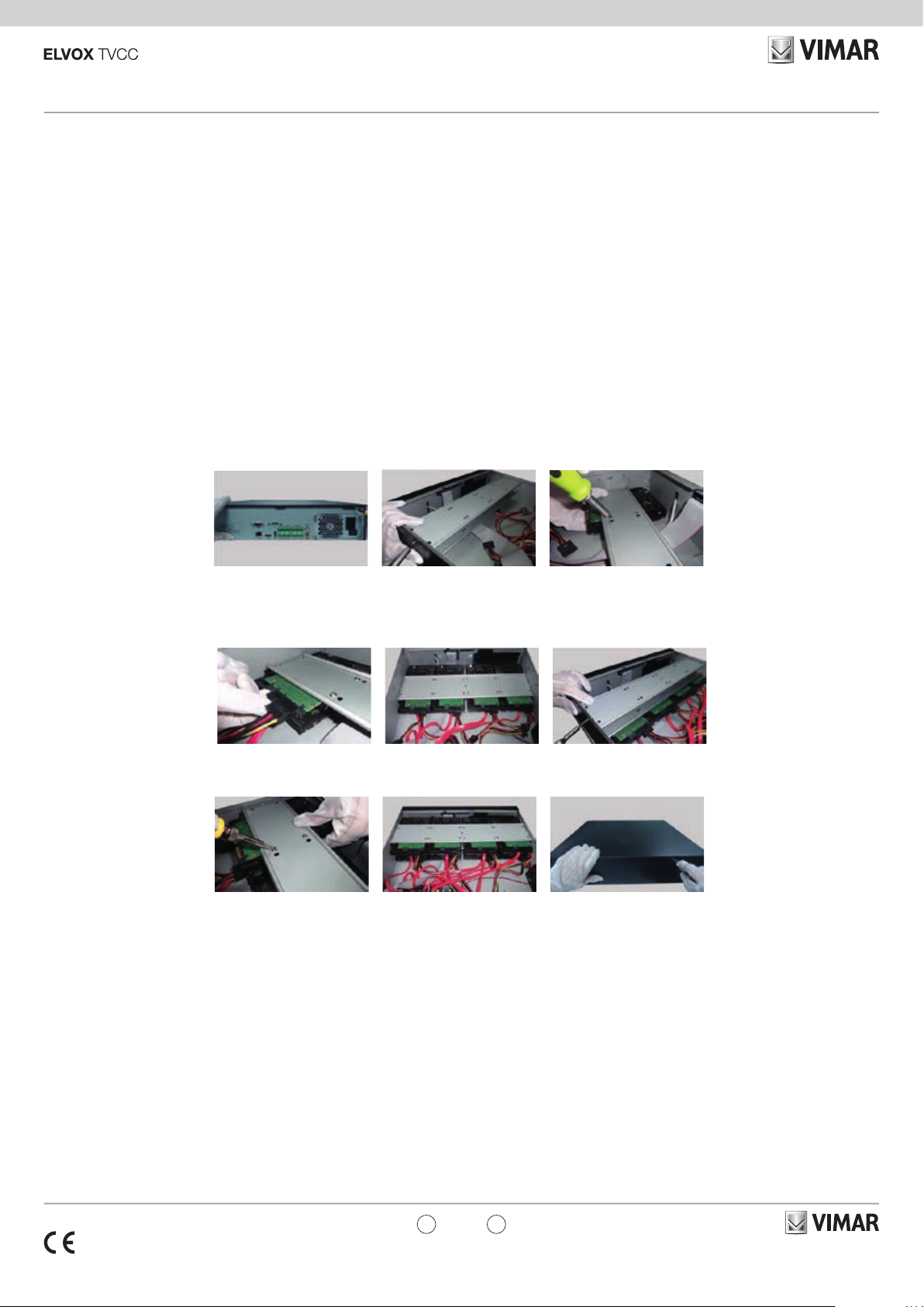
1.1 Installazione del disco rigido
Utilizzare il disco rigido raccomandato dal costruttore per garantire la
sicurezza. Calcolare la capacità dell’HDD in base alle impostazioni di
registrazione. Calcolo della capacità di registrazione”. Questa serie di
prodotti supporta l’installazione di 8 HDD SATA.
1 - Aprire il coperchio e allentare le viti per estrarre la barra di montaggio
superiore, quindi installare l’HDD.
2 - Collegare i cavi di alimentazione e dati e installare gli altri HDD seguendo il metodo sopra citato e reinstallare la barra di montaggio superiore.
64 channel NVR, Pentaplex function. H265 video compression. 64
channels Real Time (5 Mpx max), HDD not included, sata x 8 max 6TB
for HDD, 1 IN/OUT audio connections, alarms management 8 In / 4 out,
3 USB, HDMI with 4K resolution, remote control, QRCODE, privacy
masking, motion, ONVIF protocol, CVM software.
1 Hardware Installation
Check the unit and the accessories after getting the device. Please don’t
power up the unit till the physical installation is complete.
1.1 Install Hard Drive
Please use the hard drive the manufacturers recommend specially for
security and safe eld. Please calculate HDD capacity according to
the recording setting. Calculate Recording Capacity”. This series of the
product support to install 8 SATA HDDs
1 - Open the cover and loosen the screws to take out the upper mounting
bar, and then install the HDD.
2 - Connect the power and data cables and install the other three HDDs
according to above-mentioned method and install back the upper mounting bar.
3 - Installare i quattro HDD superiori e reinstallare il coperchio.
Nota: in alcuni modelli potrebbe essere presente una sola barra di montaggio. Di conseguenza è possibile installare solo quattro HDD.
2 Introduzione
2.1 Riepilogo
Basata sulle tecnologie SoC (System-on-Chip) e sui sistemi embedded
più all’avanguardia del settore, questa serie di NVR adotta l’ultimo design
di interfaccia utente e supporta la gestione intelligente delle telecamere
IP e della ricerca per fascia oraria, delle registrazioni. Questa serie di
NVR, di grande potenza e semplicità di utilizzo, è dotata di un’eccellente
qualità dell’immagine e di un sistema stabile. Contiene prodotti per la
gestione centralizzata del monitoraggio ad elevate prestazioni e qualità,
progettata appositamente per il settore del monitoraggio di video di rete.
Questa serie di NVR è applicabile ai sistemi di sicurezza per banche,
scuole, impianti domotici, traco, tutela dell’ambiente, supermercati, stazioni di rifornimento, zone residenziali, stabilimenti industriali, ecc
3 - Install the upper four HDDs and install back the cover.
Note: There may be only one mounting bar for some models. Thus, only
four HDDs can be installed under the mounting bar.
2 Introduction
2.1 Summary
Based on the most advanced SoC (System-on-Chip) technology and
embedded system in the eld, this series of the NVR adopt the new designed human interface and support the smart management of the IP
camera and the record search of slice. This series of the NVR which are
powerful and easy to use are provided with excellent image quality and
stable system. They are centralized monitoring management products
with high performance and high quality specially designed for network
video monitoring eld. This series of the NVR can be widely used to security system of banks at home and abroad, schools, intelligent mansions, trac, environmental protection, supermarkets, petrol service stations, residential quarters and factories and so on.
49401078A0 04 1807
IT
EN
Viale Vicenza, 14
36063 Marostica VI - Italy
www.vimar.com
Page 2
46241.H64
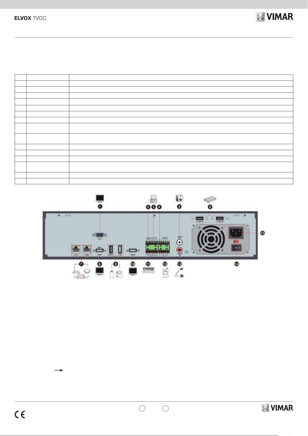
2.3 Descrizione del pannello posteriore
In questa sezione prendiamo ad esempio soltanto una parte dei pannelli
posteriore per presentare le loro interfacce e le loro connessioni. Le
interfacce e le posizioni delle interfacce valgono solo come riferimento.
Far riferimento all’apparecchiatura in dotazione.
No. Nome/Name Descrizioni/Descriptions
1 VGA Collegamento al dispositivo VGA 1920x1080/1280x1024 / Connect to monitor VGA 1920x1080/1280x1024
2 RS485 Y/Z Non disponibile in questo momento / Unavailable right now
3 ALARM OUT Uscita relè, connessione all'allarme esterno / Relay output; connect to external alarm
4 GND Massa / Grounding
5 AUDIO OUT Uscita audio connessione agli altoparlanti / Audio output; connect to sound box
6 e-SATA1/ e-SATA2 Connessione da HDD con interfaccia e-SATA / Connect to HDD with e-SATA interface
7 LAN1/LAN2 Porta di rete / Network port
8 HDMI2
9 USB3.0/USB
10 HDMI1 Collegamento al dispositivo di visualizzazione ad alta denizione 4K x 2K / Connect to 4K×2K high denition display device
11 RS485 A/B Connessione alla tastiera. A è TX+; B è TX- / Connect to keyboard. A is TX+; B is TX12 ALARM IN Allarmi di ingresso per sonnessione sensori / Alarm inputs for connecting sensors
13 AUDIO IN
14 POWER SWITCH Premere l'interruttore per accemdere o spegnere on/o l'NVR / Press the switch to turn on/o the NVR
15 POWER SUPPLY Interfaccia di alimentazione / Power supply interface
Collegamento 1920×1080 high dispositivo di visualizzazione ad alta denizione /
Connect to 1920×1080 high denition display device
Interfacce USB3.0 e USB 2.0, per connesssione dispositivo salvataggio dati USB o mouse USB /
USB 3.0 and USB 2.0 interface, connect USB storage device or USB mouse
Ingresso audio; connessione a dispositivo di ingresso audio, per esempio un microfono, un pickup, ecc /
Audio input; connect to audio input device, like microphone, pickup, etc
2.3 Rear Panel Descriptions
Here we only take a part of real panels for example to introduce their
interfaces and connections. The interfaces and locations of the interfaces
are only for references. Please take the real object as the standard.
3 Guida all’utilizzo di base
3.1 Avvio e spegnimento
Prima di collegare l’unità all’alimentazione, vericare che tutti i
collegamenti siano stati eseguiti correttamente. Un corretto avvio e
arresto è estremamente importante per la durata del dispositivo.
3.1.1 Avvio
1 - Collegare il dispositivo di visualizzazione in uscita all’interfaccia
VGA/HDMI del NVR.
2 - Collegare il mouse e accendere. Il dispositivo si avvia e il LED di
alimentazione diventa blu.
3 - Comparirà una procedura guidata (selezionare la lingua del display
la prima volta che si utilizza il NVR). Per ulteriori dettagli, fare
riferimento a 4.1 Procedura guidata per l’avvio.
3.1.2 Spegnimento
1 - Fare clic su Start Shutdown (arresto) e comparirà la nestra di
arresto. Selezionare “Shutdown” (“Arresto”) all’interno della nestra.
Dopo un momento di attesa, l’unità si spegnerà facendo clic sul
pulsante “OK”.
2 - Scollegare l’alimentazione.
49401078A0 04 1807
3 Basic Operation Guide
3.1 Startup & Shutdown
Please make sure all the connections are done properly before you
power on the unit. Proper startup and shutdown are crucial to expending
the life of your device.
3.1.1 Startup
1 - Connect the output display device to the VGA/HDMI interface of the
NVR.
2 - Connect with the mouse and power. The device will boot and the
power LED would turn blue.
3 - A WIZARD window will pop up (you should select the display language
the rst time you use the NVR). Refer to 4.1 Startup Wizard for
details.
3.1.2 Shutdown
You can power o the device by using remote controller or mouse.
By remote controller:
1 - Press Power button. This will take you to a shutdown window. The
unit will power o after a while by clicking “OK” button.
2 - Disconnect the power.
IT
EN
Viale Vicenza, 14
36063 Marostica VI - Italy
www.vimar.com
Page 3

46241.H64
3.2 Controllo del mouse
•
Controllo del mouse nell’interfaccia Anteprima Live e Riproduzione
Nell’interfaccia Anteprima Live e Riproduzione, fare doppio clic
su qualsiasi nestra della telecamera per visualizzare la nestra
in modalità a schermo singolo; fare nuovamente doppio clic per
ripristinare le dimensioni precedenti.
Nell’interfaccia Anteprima Live e Riproduzione, se le interfacce
vengono visualizzate a schermo intero, portare il mouse sulla parte
inferiore dell’interfaccia per far apparire una barra degli strumenti. La
barra degli strumenti scomparirà in automatico spostando il mouse in
un’altra posizione per un po’ di tempo; portare il mouse sulla destra
dell’interfaccia per far apparire un pannello, il pannello scomparirà in
automatico spostando il mouse in un’altra posizione.
• Controllo del mouse nell’immissione testo
Portare il mouse sulla casella di immissione testo, quindi fare clic sulla
casella. La tastiera di immissione comparirà in automatico.
Nota:
Il mouse è lo strumento predenito per tutte le operazioni, salvo
diversa indicazione.
4 Procedura guidata e interfaccia principale
4.1 Procedura guidata per l’avvio
Le icone del disco verranno visualizzate in alto
nell’interfaccia di avvio. È possibile visualizzare
il numero e lo stato di ciascun disco in maniera
veloce e intuitiva attraverso queste icone (
disco assente;
RW disponibile).
È possibile congurare rapidamente l’NVR
tramite la procedura guidata d’impostazione per
far funzionare l’NVR normalmente. È necessario
congurare la procedura guidata quando l’NVR
viene avviato per la prima volta (oppure fare clic su
“Skip” (Salta) per annullare la procedura guidata la
volta successiva).
: disco non disponibile; : disco
:
3.2 Mouse Control
• Mouse control in Live Preview & Playback interface
In the live preview & playback interface, double click on any camera
window to show the window in single screen mode; double click the
window again to restore it to the previous size.
In the live preview & playback interface, if the interfaces display in
full screen, move the mouse to the bottom of the interface to pop up
a tool bar. The tool bar will disappear automatically after you move
the mouse away from it for some time; move the mouse to the right
side of the interface to pop up a panel and the panel will disappear
automatically after you move the mouse away from it.
• Mouse control in text-input
Move the mouse to the text-input box and then click the box. The
input keyboard will pop up automatically.
Note:
Mouse is the default tool for all operations unless an exception as
indicated.
4 Wizard & Main Interface
4.1 Startup Wizard
The disk icons will be shown on the top of the
startup interface. You can view the number and
status of each disk quickly and conveniently
through these icons (
: RW available disk).
disk;
You can quickly congure the NVR by wizard
setup to make the NVR work normally. You must
congure the wizard if you start the NVR for the
rst time (or click “Skip” to cancel the wizard next
time).
: no disk; : unavailable
Fare clic su “Wizard Setup” (Procedura Guidata
Impostazione) per iniziare la procedura guidata. Le
fasi di impostazione sono le seguenti.
1 - Accesso al sistema. Impostare la propria
password o utilizzare quella predenita quando
viene utilizzata la procedura guidata per la prima
volta (il nome utente predenito del sistema è
admin; la password predenita di admin è 123456);
selezionare il nome utente di accesso e inserire la
password corrispondente la volta successiva.
Fare clic su “Edita Security Question” (Modica
domanda di sicurezza) per impostare le domande e
le risposte di sicurezza per la password dell’admin.
Fare clic su “Next” (Avanti) per continuare oppure
fare clic su “Cancel” (Annulla) per uscire dalla
procedura guidata.
2 - Congurazione di data e ora La data e
l’ora del sistema devono essere impostate se la
procedura guidata viene utilizzata per la prima
volta. Fare riferimento alla gura seguente.
Impostare il fuso orario, l’ora del sistema, il formato
della data e il formato dell’ora. Il DST sarà abilitato
per impostazione predenita se il fuso orario
selezionato comprende DST. Fare clic su “Next”
(Avanti) per continuare.
Click “Wizard Setup” to start wizard. The setting
steps are as follows.
1 - System Login. Set your own password or use
the default when you use the wizard for the rst time
(the default username of the system is admin and
the default password of admin is 123456); select
the login username and enter the corresponding
password next time.
Click “Edit Security Question” to set questions and
answers for password security of admin.
Click “Next” to continue or click “Cancel” to exit the
wizard.
2 - Date and Time Conguration. The date and
time of the system need to be set up if you use
the wizard for the rst time. Refer to the following
gure. Set the time zone, system time, date format
and time format. The DST will be enabled by default
if the time zone selected includes DST. Click “Next”
to continue.
49401078A0 04 1807
IT
EN
Viale Vicenza, 14
36063 Marostica VI - Italy
www.vimar.com
Page 4

46241.H64
3 - Impostazioni di rete. Selezionare “Obtain an
IP address automatically” (Ottenere un indirizzo IP
automaticamente) e “Obtain DNS automatically”
(Ottenere DNS automaticamente) per ottenere
l’indirizzo IP e DNS automaticamente, o immettere
manualmente l’indirizzo IP, maschera di sottorete,
gateway, DNS preferito e DNS alternativi.
Immettere la porta HTTP, la porta RTSP e la porta
Server. Fare clic su “Next” (Avanti) per continuare.
4 - QRCode. È possibile scansionare il QRCode
attraverso l’applicativo client installato nel telefono
cellulare o nel PAD per accedere istantaneamente.
Per maggiori dettagli vedere il paragrafo 5.2
Sorveglianza Client Mobile.
3 - Network Settings. Check “Obtain an IP address
automatically” and “Obtain DNS automatically”
to get the IP address and DNS automatically, or
manually input IP address, subnet mask, gateway,
preferred DNS and alternate DNS. Input the HTTP
port, RTSP port and Server port. Click “Next” to
continue.
4- QRCode. You can scan the QRCode through
mobile client which is installed in the mobile phone
or PAD to log in the mobile client instantly. Please
refer to 5.2 Mobile Client Surveillance for details.
5 - Aggiunta Telecamera. Fare clic su “Refresh”
(Aggiorna) per aggiornare l’elenco delle telecamere IP
online che si trovano nella stessa rete locale dell’NVR
e fare clic
Fare clic su “Add All” (Aggiungi Tutto) per aggiungere
le telecamere nell’elenco. Fare clic
per aggiungere la telecamera cercata.
per eliminare
la telecamera aggiunta. Fare clic su “Delete All”
(Elimina tutto) per eliminare tutte le telecamere
aggiunte.
Fare clic su per modicare la telecamera
IP cercata come mostrato in basso a sinistra.
Immettere il nuovo indirizzo IP, la subnet mask,
il gateway, il nome utente e la password della
telecamera. Fare clic sul pulsante “OK” per salvare
le impostazioni.
5- Add Camera. Click “Refresh” to refresh the list
of online IP cameras which are in the same local
network with NVR and then click
to add the
searched camera. Click “Add All” to add all the
cameras in the list. Click
to delete the added
camera. Click “Delete All” to delete all the added
cameras.
Click
to edit the searched IP camera as shown
on the below left. Input the new IP address, subnet
mask, gateway, username and the password of the
camera. Click “OK” to save the settings.
49401078A0 04 1807
IT
EN
Viale Vicenza, 14
36063 Marostica VI - Italy
www.vimar.com
Page 5

46241.H64
Fare clic su per modicare la telecamera
aggiunta come mostrato in alto a destra.
Immettere il nuovo nome della telecamera,
l’indirizzo IP, la porta, il nome utente e la password
della telecamera. È possibile fare clic sul pulsante
“Test” (Prova) per vericare l’esattezza delle
informazioni immesse. Fare clic sul pulsante “OK”
per salvare le impostazioni. È possibile modicare
il nome della telecamera IP solo quando la
telecamera aggiunta è online. Fare clic su “Next”
(Avanti) per continuare.
6 - Impostazioni disco. È possibile visualizzare
il numero disco, la capacità disco dell’NVR e il
numero di serie, lo stato R&W del disco. Fare clic
su “Formatting” (Formattazione) per formattare il
disco. Fare clic su “Next” (Avanti) per continuare.
7 - Impostazioni registrazione. Sono disponibili
due modalità di registrazione: automatica e
manuale.
Automatica: Selezionare una modalità
automatica nell’interfaccia come indicato di
seguito, quindi fare clic sul pulsante “OK” per
salvare le impostazioni.
Manuale: Impostare “Sensor Record”
(Registrazione Sensore), “Motion Record”
(Registrazione Movimento) e “Schedule Record”
(Registrazione Programmazione) di ciascuna
telecamera. Fare clic sul pulsante “OK” per
salvare le impostazioni.
Click
on the above right. Input the new camera name,
IP address, port, username and the password
of the camera. You can click “Test” to test the
eectiveness of the input information. Click “OK” to
save the settings. You can change the IP camera
name only when the added camera is online. Click
“Next” to continue.
6 - Disk Settings. You can view the disk number,
disk capacity of the NVR and serial number, R&W
status of the disk. Click “Formatting” to format the
disk. Click “Next” to continue.
7- Record Settings. Two record modes are
available: auto and manual.
Auto: Select one auto mode in the interface as
shown below and then click “OK” button to save
the settings.
Manual: Set the “Sensor Record”, “Motion
Record” and “Schedule Record” of each camera.
Click “OK” to save the settings.
to edit the added camera as shown
5 Congurazione NAT
Fare clic su StartSettingsNetworkNAT (Start/Impostazioni/Rete/
NAT) per passare all’interfaccia per la congurazione NAT. Selezionare
il pulsante “Enable” (Abilita), quindi selezionare l’indirizzo server NAT
(nat.autonat.com per impostazione predenita). Fare clic sul pulsante
“Apply” (Applica) per salvare le impostazioni.
5.1 Visualizzazione dello stato di rete
Fare clic su StartSettingsNetworkNetwork Status (Start/Settings/
Rete/Stato rete) per visualizzare lo stato di rete o fare clic sull’icona
sulla barra degli strumenti in fondo all’interfaccia di anteprima live per
visualizzare facilmente lo stato di rete.
5.2 Sorveglianza remota
Sorveglianza Client Mobile
1 - Attivare la funzione NAT nell'NVR.
2 - Scaricare e installare il client mobile “SuperLive
Plus” in un dispositivo mobile con sistema operativo
Android o iOS.
3 - Eseguire il client mobile, andare all'interfaccia
"Add Device" (Aggiungi dispositivo), quindi fare
clic su
(Andare al percorso StartSettingsSystem
InformationBasic (Start/Impostazioni/Sistema/
Informazioni/Base) per visualizzare il QRCode
dell'NVR).
4 - Dopo aver scansionato il QRCode con
successo, immettere la password di login nel client
mobile.
Nota: i manuali completi e i software CVM.exe,
Iptool.exe e Diskcalculator.exe sono disponibili
nella scheda prodotto consultabile nel sito:
www.vimar.com
per scansionare il QRCode dell'NVR
5 NAT Conguration
Click StartSettingsNetworkNAT to go to the interface for NAT
conguration. Check “Enable” and then select the NAT server address
(nat.autonat.com by default). Click “Apply” to save the settings.
5.1 View Network Status
Click StartSettingsNetworkNetwork Status to view the network
status or click
interface to view network status conveniently.
on the tool bar at the bottom of the live preview
5.2 Remote Surveillance
Mobile Client Surveillance
1 - Enable NAT in the NVR.
2 - Download and install the mobile client “SuperLive
Plus” into the mobile device with the Android or iOS
system.
3 - Run the mobile client, go to the “Add
Device” interface and then click
scan the QRCode of the NVR (Go to
StartSettingsSystemInformationBasic to
view the QRCode of the NVR).
4 - After scanning the QRCode successfully, input
the login password to log in mobile client.
Note: the complete manual of instructions and
CVM.exe, Iptool.exe and Diskcalculator.exe
software are available in the online Product info on:
www.vimar.com
to
49401078A0 04 1807
IT
EN
Viale Vicenza, 14
36063 Marostica VI - Italy
www.vimar.com
Page 6

46241.H64
Regole di installazione.
L’installazione deve essere effettuata da personale qualificato con l’osservanza delle disposizioni regolanti l’installazione del materiale elettrico
in vigore nel paese dove i prodotti sono installati.
Conformità Normativa
Direttiva BT, Direttiva EMC
Norme EN 60950-1, EN 55032, EN 55024, EN 61000-3-2, EN 61000-3-3
RAEE - Informazione agli utilizzatori
Il simbolo del cassonetto barrato riportato sull’apparecchiatura o
sulla sua confezione indica che il prodotto alla ne della propria
vita utile deve essere raccolto separatamente dagli altri riuti. L’utente dovrà, pertanto, conferire l’apparecchiatura giunta a ne vita agli
idonei centri comunali di raccolta dierenziata dei riuti elettrotecnici ed
elettronici. In alternativa alla gestione autonoma, è possibile consegnare
gratuitamente l’apparecchiatura che si desidera smaltire al distributore,
al momento dell’acquisto di una nuova apparecchiatura di tipo equiva-
lente. Presso i distributori di prodotti elettronici con supercie di vendita
di almeno 400 m2 è inoltre possibile consegnare gratuitamente, senza
obbligo di acquisto, i prodotti elettronici da smaltire con dimensioni in-
feriori a 25 cm. L’adeguata raccolta dierenziata per l’avvio successivo
dell’apparecchiatura dismessa al riciclaggio, al trattamento e allo smaltimento ambientalmente compatibile contribuisce ad evitare possibili eetti negativi sull’ambiente e sulla salute e favorisce il reimpiego e/o riciclo
dei materiali di cui è composta l’apparecchiatura.
Installations rules.
Installation should be carried out by qualied sta in compliance with the
current regulations regarding the installation of electrical equipment in the
country where the products are installed.
Regulatory compliance
LV directive, EMC directive.
Standards EN 60950-1, EN 55032, EN 55024, EN 61000-3-2, EN 61000-3-3
WEEE - User information
If the crossed-out bin symbol appears on the equipment or packaging, this means the product must not be included with other
general waste at the end of its working life. The user must take
the worn product to a sorted waste center, or return it to the retailer
when purchasing a new one. Products for disposal can be consigned
free of charge (without any new purchase obligation) to retailers with
a sales area of at least 400 m
2
, if they measure less than 25 cm. An
ecient sorted waste collection for the environmentally friendly disposal of the used device, or its subsequent recycling, helps avoid the
potential negative eects on the environment and people’s health, and
encourages the re-use and/or recycling of the construction materials.
49401078A0 04 1807
Viale Vicenza, 14
36063 Marostica VI - Italy
www.vimar.com
 Loading...