

Page 1

Instructions manual
21553
Multimedia video touch screen 10in Full Flat.
Page 2

Page 3

1
Indice
1. DESCRIPTION ……………………………………………………………………………………………………… 2
1.1 Caratteristiche principali ……………………………………………………………………………………… 2
2. MAIN MENÙ ………………………………………………………………………………………………………… 3
2.1 Notices ………………………………………………………………………………………………………… 4
3. SETTINGS…………………………………………………………………………………………………………… 5
3.1 General ………………………………………………………………………………………………………… 5
3.2 Vimar Web Server IP network ………………………………………………………………………………… 12
3.3 Video door entry system ……………………………………………………………………………………… 14
3.4 User Management ……………………………………………………………………………………………… 58
3.5 Update ………………………………………………………………………………………………………… 65
3.6 Procedure for Installing Applications from Market Vimar Group …………………………………………… 67
5. INSTALLATION RULES ………………………………………………………………………………………… 70
4. REGULATORY COMPLIANCE …………………………………………………………………………………… 70
Page 4
2
1. DESCRIPTION
In a By-me automation system in which the web server is installed, the multimedia video touch screen enables
complete control of lights, roller shutters, HVAC, speaker system, scenarios, event programs, load control, power
consumption management (Energy Guard) and intrusion detection alarm system. The multimedia video touch screen
can moreover also be used as a video door entry unit and it manages all the functions of the Due Fili (Two Wire)
video door entry system (displays images from panel and from video cameras, voice communication with speech
unit, audio door entry units and call buttons, opening electrical lock, etc.). The connection with the web server will
enable not only supervising and controlling the entire home automation system (automation, intrusion detection
alarm system and video door entry system) but also browsing certain websites (weather forecasts, news, RSS feed
reader, web radio), displaying video or photographs, listening to music (mp3 files), writing notes and linking them to an
acoustic alarm signal (date and time), creating graphic notes with real drawings thanks to the "blackboard" function.
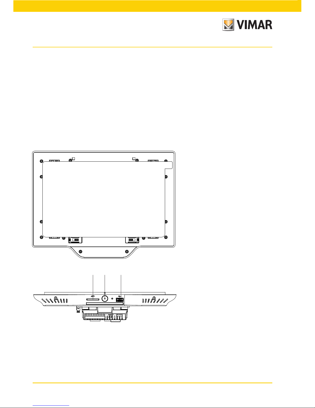
1.1 Main characteristics.
Description
Display
CBA
A: SDHC port
B: ON/OFF button
C: USB port
ON/OFF button:
• ON: with the device switched off, press once to turn on the video touch screen.
• With the device switched on, press once to display the context menu.
• OFF: with the device switched on, press and keep pressed until the video touch screen displays the off icon.
Video backlighting lifetime: 10,000 hours (at 25°C)
The lifetime is defined as the estimated time for the brightness to fall to 50% of the initial value.
Page 5
3
Main Menu
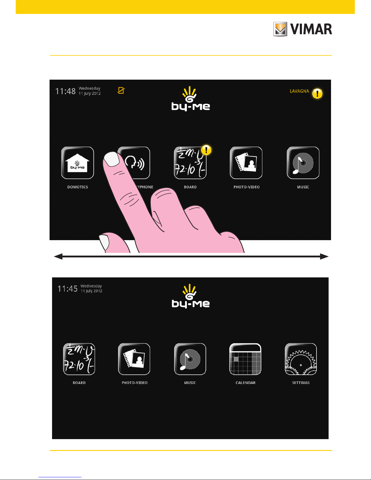
2. MAIN MENU
To display all the other icons, scroll horizontally with your finger over the area covering them.
Page 6
4
IMPORTANT: The default passwords, namely the ones to use when first switching on, are the following:
- Administrator password: admin
- Installer password: inst
For all the details on user management (Administrator, Installer, etc.) and the associated functions please see
chap. 3.4 on page 58.
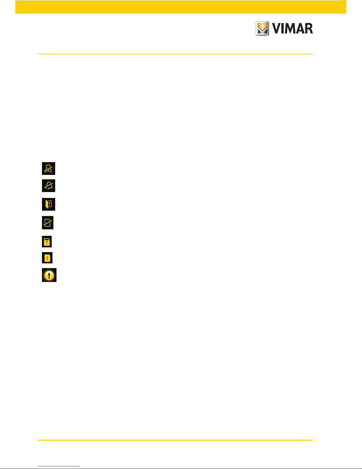
2.1 Notices.
In case of special settings or events (for example video door entry call, alarm silencing, etc.) the multimedia video
touch screen will display the following warnings:
- : User absent
- : Ringtone off
- : "Door open" indicator
- : SD card not inserted
- : SD card inserted 51-75%
- : SD card inserted 76-100%
- : Indicator for "lost call" (video door entry system) and "new note" (blackboard)
Main Menu
Page 7

5
3. SETTINGS
From the main menu, touching the icon takes you to the Settings menu.
3.1 General.
Touching the icon displays the following options:
- System info;
- Reserved System info;
- Date and Time;
- Language and Unit of Measurement;
- Energy Saving;
- Line Out;
- Configuration Save - Restore.
Settings
Page 8

6
• System info
Touching the icon displays the software release and the main features of the multimedia video
touch screen.
Settings
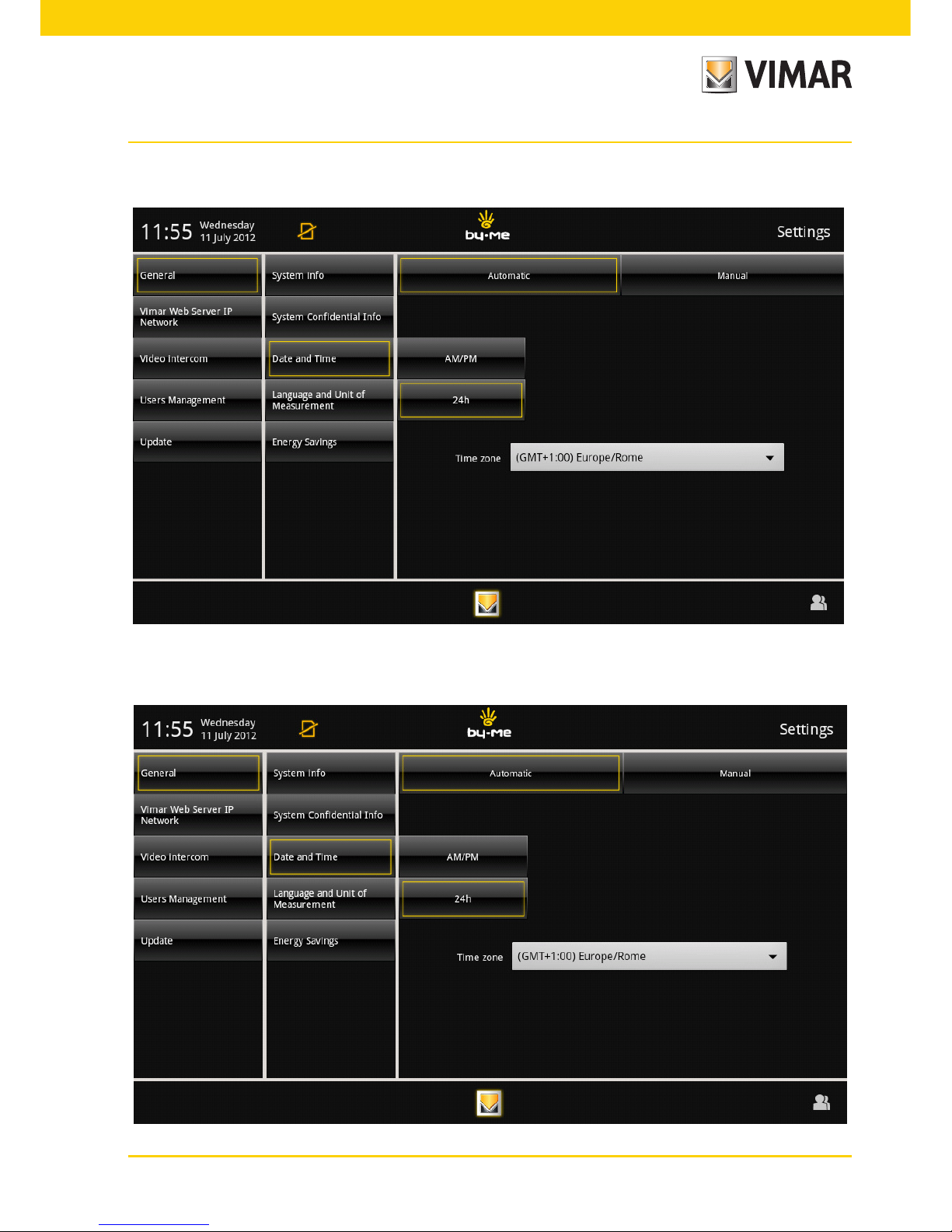
• Date and Time
By touching the icon it is possible to adjust the time and date displayed.
By touching the relevant icons it will be possible to select Automatic or Manual mode, viewing the time in AM/PM
or 24h mode, the time zone and set the current date.
Page 9
7
Automatic:
Manual:
Settings
Page 10

8
• Language and Unit of Measurement
By touching the icon it is possible to select the language in which all the words will be
displayed and the unit of measurement with which the multimedia video touch screen will display the temperature
of the various system environments.
Touch the drop-down menu on "Language" and select the desired one.
Touch the icon corresponding to the unit of measurement for the temperature in *C or °F; the set unit of measurement will then be used in the Weather application.
Settings
Page 11
9
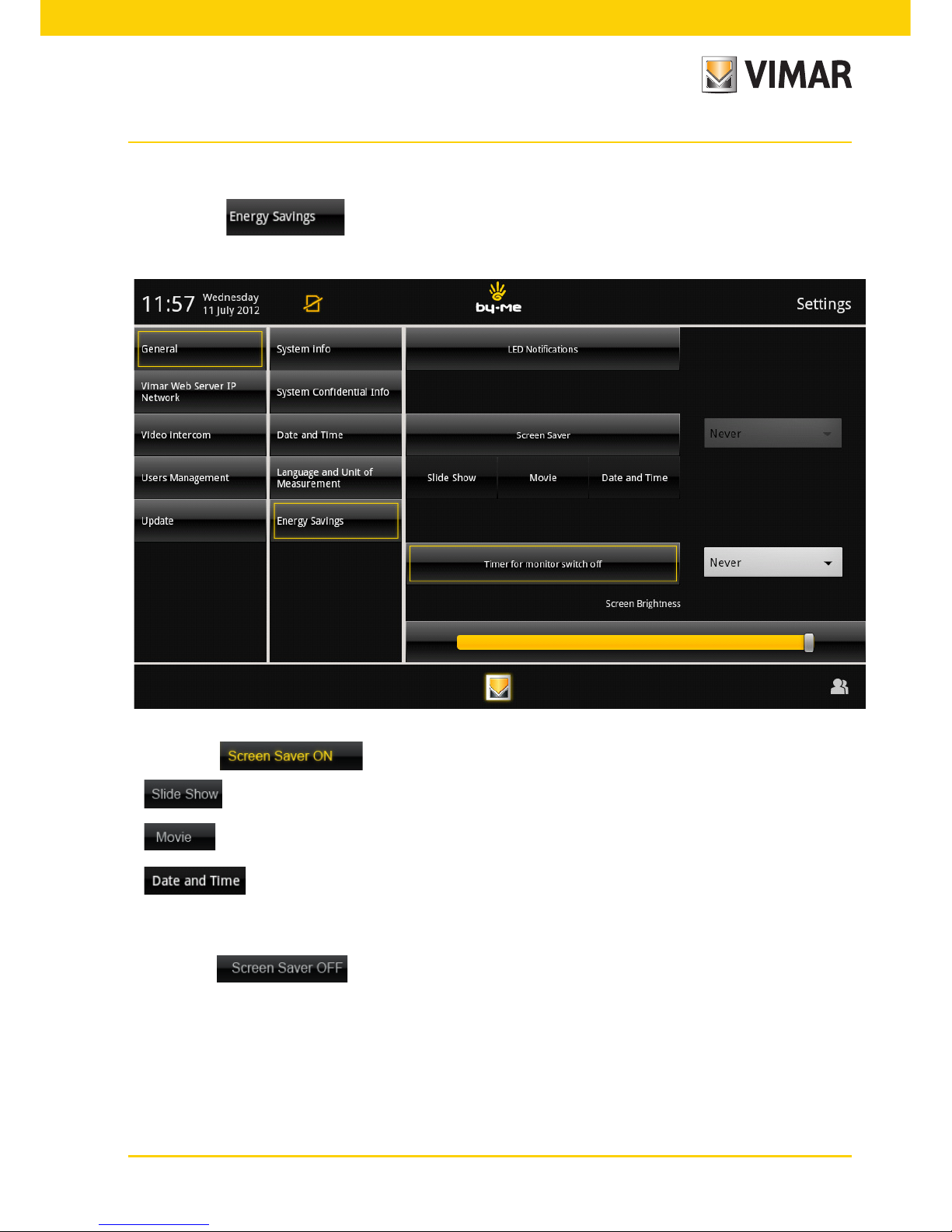
• Energy Saving
Touching the icon takes you to the screen for setting the screen saver for the multimedia
video touch screen.
By touching it is possible to choose different types of screen saver:
- enables selecting a picture folder on the SD card;
- enables selecting a video on the SD card;
- enables viewing the current day, date and time.
The drop-down menu alongside the "Screen Saver ON" icon is used to set the time-out at the end of which the
screen saver will be displayed.
By selecting it is possible to set only the "monitor switch-off timer"; the display of the video
touch screen will switch off.
The drop-down menu alongside the "monitor switch-off timer" icon is used to set the time-out at the end of
which the display will switch off.
Settings
Page 12

10
• Line Out
With this screen you can monitor the audio signal of the multimedia video touch screen and also an additional
independent sound source.
Touching the icon displays the icons for single or joint control of the audio channels.
To adjust the default volume of the speakers during a call, touch the cursor of the scroll bar and move it to the left
or right according to the desired volume (the level is highlighted by the illumination of the bar).
Settings
Page 13

11
• Configuration Save - Restore
Touching the icon takes you to the screen that is used to save the configuration made or
restore the one prior to the changes.
Then touch the icon or to carry out the desired operation.
When saving the configuration a pop-up is displayed that allows you to choose where you want to save it.
Settings
Page 14

12
Vimar Web Server IP network
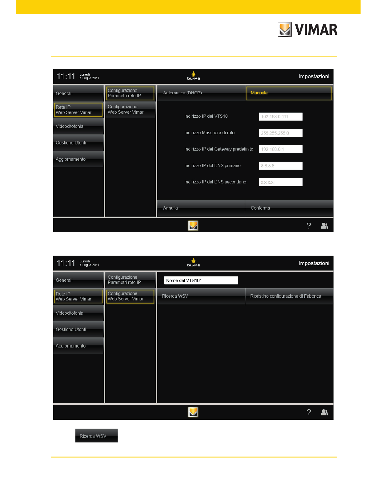
3.2 VIMAR WEB SERVER IP NETWORK.
Touching the icon displays the configuration options for the network settings and for the
interfacing between the multimedia video touch screen and the Vimar Web Server 01945.
• IP Network Parameters Configuration
The network parameters can be set automatically by the device or by manually entering the addresses to be
linked.
Page 15
13
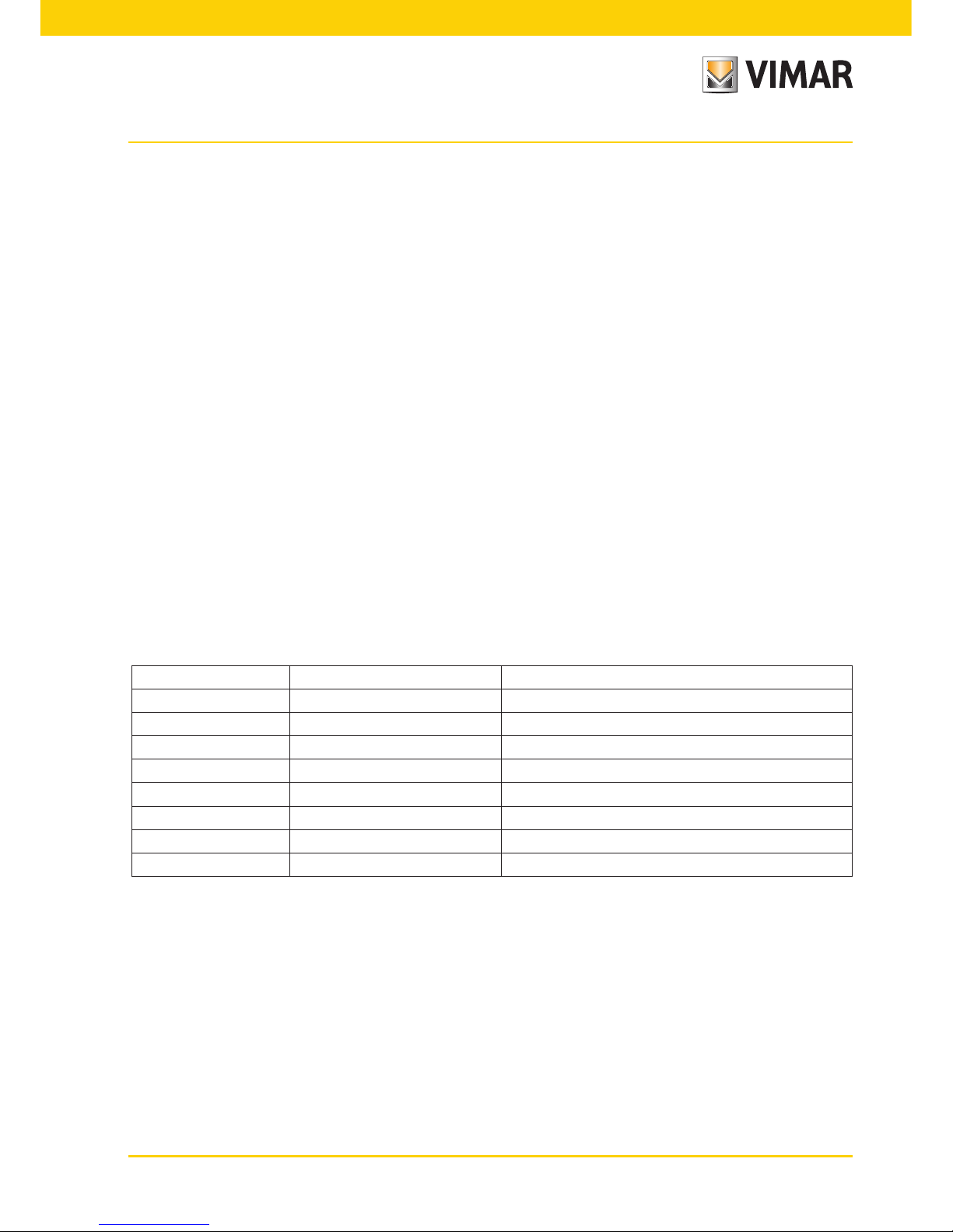
Vimar Web Server IP network
• Vimar Web Server Configuration
With the icon you seek and automatically link the Web Server 01945 to the multimedia video
touch screen.
Page 16

14
3.3 VIDEO DOOR ENTRY SYSTEM.
Type of system.
The multimedia video touch screen can be used solely on video door entry systems of the Two Wire digital type;
it will therefore be necessary to use solely power supplies in the Two Wire range (for the specifications see the
relevant manuals). To create the audio and video function the type of connection, both toward the pillar and toward
the speech unit, is made with a "2 wire non-polarized" bus cable.
The Two Wire system enables making types of systems in which the identification of the devices and controls is digital.
Depending on the configuration of the system, each of the connected devices is characterized by a numerical
code between 1 and 200 (the value must be univocal) and is able to receive and send data packets containing all
the information related to the management of the communication; each data packet is composed of the identification of the destination device and the command that the latter must actuate.
All the control operations typical of a video door entry system such as, for instance, call, electrical lock opening,
stair lighting, etc., are therefore coded.
The voice unit for the voice communication and the video signal for viewing the images instead are still analogue signals.
Lastly as regards the type of cables to use for the connection between the components of the system, both toward
the pillar and toward the speech unit, it is recommended to use the twisted bipolar BUS cable with a cross-section
of 1 mm² (type art. 02037 or the equivalent).
In the case of Due Fili video door entry systems where there are monitors 21550/20550/14550 combined
with the module 01963 and with the presence of By-me home automation modules 01960 (or control pan-
els with video door entry unit 01956), the following applies:
- The maximum number of indoor stations per pillar or after separator 692S, made with art.
21550/20550/14550 + 01960 + 01963, is 4 (that is a maximum of 4 independent home automation subsystems connected to the pillar of the Due Fili system).
- It is possible to connect other Due Fili devices (art. 21553, 21554, 01955, 20557, 20577,
21550/20550/14550/+01963, etc.) up to a maximum of 32 total devices per pillar or after separator 692S.
In all the above cases, if you need to exceed the maximum number of devices, it is necessary to expand
the system by using separators 692S and their power supply units creating separate galvanic isolations.
Advantages of the Two Wire system.
The most important advantage offered by the Two Wire system, compared to other video door entry systems
(classic “8 wire + n” analogue or digital with multi-wire DigiBus), is its use in wiring the whole system with just 2
conductors, twisted and not polarized, on which the data, audio signal, video signal and necessary power supply
are conveyed to the connected devices.
Thanks to this characteristic, the system is therefore ideal to be used both in small-medium residential systems
and in large building complexes (up to a maximum of 200 indoor stations) because it considerably simplifies the
wiring operations.
Another advantage of using the Two-Wire system is its extreme flexibility in the case of subsequent system expansion; it is possible, in fact, to add new indoor stations simply with the aid of the pillar without having to wire further
cables toward the power supply.
The digital management of all the commands (call bell duration, type of bell, call time duration, answer time duration, entry with password or programmed key, etc.) lastly enables programming all the parameters of the devices
according to the different requirements of each user.
Video door entry system
Page 17
15
Video door entry system
Main technical characteristics of the system.
• All the system elements are connected via bus with 2 wires that are twisted and not polarized
• Up to a total of 200 users, comprising audio and video door entry units
• Up to 15 entry panels, audio and video
• In colour video systems it is necessary to use the cable art. 02037 for a maximum distance of 75 m (for all the
details see the Two Wire technical documentation)
• Up to 16 independent pillars
• Up to 16 auxiliary functions in the same system
• Audio and video door entry units with confidential conversation
•
Audio intercom between all the audio and video door entry units or between groups of audio and video door entry units
• Differentiated call tone for entry panel, door panel and intercom
• Possibility of including additional ringtones in parallel with the audio or video door entry unit
• Multiple routing of the same call (up to 8 devices)
• Group video door entry call with only the group leader switching on (with no supplementary power supplies) or
with all the video door entry units of the group switching on at the same time (with supplementary power supplies)
• Simple programming of the devices for the standard functions via panel and device buttons
• Advanced device programming via personal computer (pc), USB 02024 interface and “EVCom” software.
Description of terminals.
The connector, on the pillar side, through which all the connections from and to the video door entry unit are
made, has 8 terminals (inputs and outputs) divided according to the functions described in the table on the following page.
Operation of the Two Wire system.
The Two Wire system enables digital coding of the devices and the commands that are sent or that come from the
external panel; the latter can be considered as the MASTER device (main appliance that manages the communication between the digital devices in the system) while every other single digital device (including the secondary
panels) can be considered as a SLAVE (secondary appliance that is piloted/controlled by the master).
The entry panel is therefore essential for the operation of the Two Wire system and must always be installed in
the system; all the programming parameters (call time, type of bell, electrical lock opening, code numbers of the
indoor stations, etc.) are set and saved (until the next programming) in the main external panel (EEPROM memory).
For programming the panel and all the parameters correlated with it, see the related technical documentation.
Terminal number Type Function
+12 - Power supply for supplementary
CH Output Control for supplementary bell/relay
1 Imput/ Output BUS digital line
2 Imput/ Output BUS digital line
E+ Imput Supplementary power supply (+28Vdc, 24Vac)
E- Imput Supplementary power supply (GND, 24Vac)
FP Imput Landing button N.O. (doorbell function)
M - Ground reference for Landing push-button N.O.
Page 18

16
Power Supplies and other.
The power supplies and other accessories that can be used for installing the system are all those of the Two Wire
range; in particular, the following articles are recommended:
• 02030 (standard video door entry system power supply)
• 02031 (additional power supply for panels and monitor in parallel)
• 02032 (power supply for additional video cameras and landing video)
• 02020 (
separator for the division of conversation areas, intercommunicating networks and landing door panels
• 02019
(concentrator for connections of up to 4 entrance panels, of which at least one is a video door entry version)
• 02016 (audio/video interface module for external video camera)
• 02017 (expansion module for 4 video cameras with audio input to be connected to 02016)
• 02018 (active video floor distributor to adapt impedance of video signal)
• 02022 (digital relay with 2 independent contacts and maximum load of 3A 230V per contact)
As regards all the technical characteristics (supply voltage, current delivered, power input, description of terminals,
etc.), see the technical manuals.
General information on the digital controls.
The digital controls are packets of data that can be sent from/to each digital device and contain the information/
instructions that enable activating a particular function (video call, intercom call, lock opening, stair lighting, auxiliary function activation, etc.). The control is mainly composed of 3 significant fields: < receiver - command code
- sender >. An example of hexadecimal coding of a command is the following:
< 01 - 0E - FE > = LOCK
that represents the lock opening command of the main panel sent by device no. 1. Typically, in the Two Wire system, the main video door entry commands are the following:
- LOCK command
- FUNCTION F1 command
- FUNCTION F2 command
- AUX 1 SERVICE command
- AUX 2 SERVICE command
Video door entry system
Page 19

17
These commands pilot actuators that are in the panels or in special auxiliary digital relays to be set up; in the case
of the above-listed main commands (and in reference to the Two Wire panel series 0200..) the actuators are the
following:
actuator S+/S- S+(positive output 12Vdc max 200mA) with S- that closes to ground on receiving
the LOCK command.
actuator F1 Contact that closes to ground on receiving the F1 FUNCTION command.
12Vdc power supply that can be taken from the '+12V' terminal max 100mA.
To be used to control an auxiliary external relay.
actuator F2 Contact that closes to ground on receiving the F2 FUNCTION command.
12Vdc power supply that can be taken from the '+12V' terminal max 100mA.
To be used to control an auxiliary external relay.
AUX 1 SERVICE actuator Contact on digital auxiliary relay (to set up) art. 02022 (see technical documenta-
tion art. 02022)
AUX 2 SERVICE actuator Contact on digital auxiliary relay (to set up) art. 02022 (see technical documentation
art. 02022)
NOTE: There are up to a maximum of 16 AUX SERVICES in the system.
Each single command is sent by pressing a button (associated with the same command) on the device. Other
commands can be associated and programmed as preferred on the available buttons via pc, interface USB 02024
and “EVCom” software.
The main function of the device is to identify, with communication and viewing via the audio and video channels,
people asking to access the dwelling from the speech unit and to open or not open the electrical lockof the gate or door.
In addition, the video door entry unit enables implementing other additional functions that are:
- activating stair lights;
- self-starting the speech unit;
- additional auxiliary function(s) (according to the configuration of the buttons);
- intercom calls to other audio or video door entry units.
All the functions of the video door entry unit are enabled by pressing the dedicated buttons.
The main states of operation of the video door entry unit are the following:
- With display ON
- With display OFF
Video door entry system
Page 20
18
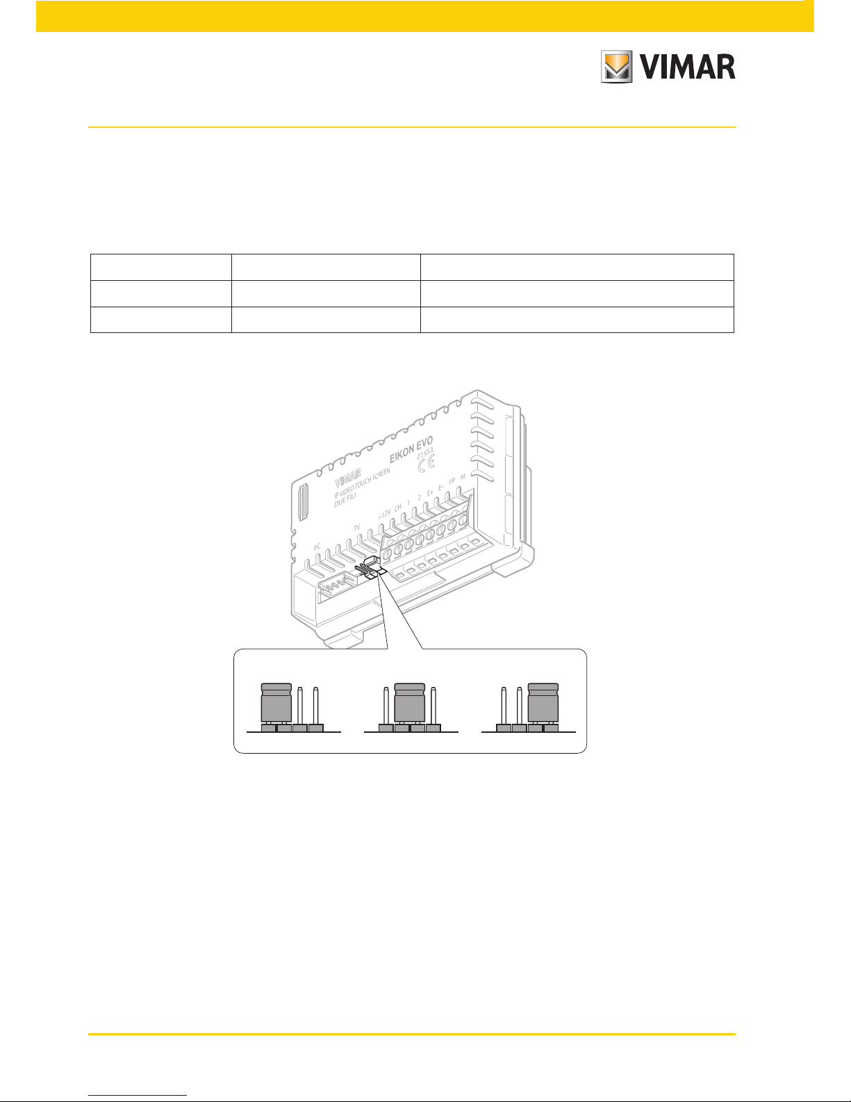
PC TV +12V CH 1 2 E+ E– FP M
IP VIDEO TOUCH SCREEN
DUE FILI
21553
EIKON EVO
A B C
Figure 7 - "TV" line termination selector
The “TV” (Termination Video) line termination selector.
The bus line (where data, video and audio signal transit) is a line that must be adapted according to the installation
topology of the plant, especially to assure the maximum quality of the video signal. The connector (TV - video
termination) must be jumpered according to the prescriptions given in the following table:
position A no termination if the bus enters and exits the device
position B termination 100 Ohm if the bus terminates in the device
position C termination 50 Ohm alternative to position B
Video door entry system
Page 21

19
Warnings for device coding and programming.
The identification phase (coding via numerical identification - ID) for some devices of the Two Wire system is done
during the programming phase while for others it is done with jumpers or dip-switches in the device and that must
be set during the phase of installation (see the instruction sheets of the single devices).
Important: It is vital, during the programming phase, for the system to have an electronic entrance panel model
(02001, 02002, 02003, 02004), identified as the “Master entrance panel.”
In an Two Wire system there must be only one Master entrance panel (identification code ID = 1). The various
devices in the system must be programmed after their identification; this programming can be carried out with
electronic entrance panel model 0200.. with a PC by means of the USB 02024 interface and the “EVCom” software.
Using the electronic entrance panels with conventional buttons (not with an alphanumeric keyboard) allows only
standard programming of the devices but not advanced programming; this programming is anyhow enough for
the operation of the devices in most systems.
Device programming phases.
For the correct configuration and programming of the system, follow this procedure in sequence:
- Install and connect all the system devices.
- For video door entry systems, set the jumper for video termination as shown on the connection diagrams.
- If present in the system code the devices 02020, 02022, 692U, 692U/C, 69AV, 02016, 69AU.
- When there are electronic entrance panels with pushbuttons, do the hardware programming of any pushbutton
modules.
- In systems with multiple electronic entrance panels, set the SLAVE panels (generally using the specific jumper)
and code without connecting the MASTER entrance panel (ID code of the SLAVE panels between 2 and 15)
- Connect and power up the MASTER entrance panel (it is the panel with ID = 1).
- Program any entrance panel parameters. The essential parameters to program are shown on the connection
diagrams.
- Code the audio and video door entry units from the MASTER entrance panel.
- Do any advanced programming of the audio and video door entry units (intercom push-buttons, group calls,
digital relay activation ….).
Video door entry system
Page 22

20
Numerical coding of the video door entry unit.
The multimedia video touch screen is identified in the system with a numerical code in the range from 1 to 200; it
is then necessary to program this code with the following procedure:
• In the main window touch the icon and subsequently the icon.
• Finally touch the icon; the numerical coding is then completed.
• Send a call to the multimedia video touch screen from the MASTER panel with the desired numerical code; if
you have a panel with an alphanumeric keyboard it is enough to key in this code and send it to the device by
pressing the confirmation button on the panel while, if you have a push-buttons panel, send the call with the
button that you want to associate with the video door entry unit on the panel.
• Lastly, check that the multimedia video touch screen answers the call (with an alphanumeric panel, key in the
set code and press the confirmation button on the panel while, if you have a push-buttons panel, press the
button corresponding to the call).
If you do not have a panel with alphanumerical buttons or single buttons it is necessary to use the USB 02024
interface with PC and “EVCom” software.
Video door entry system
Page 23

21
Secondary numerical coding of the video door entry unit.
Programming the secondary identification code is only required when you want to have more than one video door
entry unit ring at the same time with the same push-button or call code.
The video door entry units that must ring at the same time are associated with the same group; The “master” video
door entry unit is programmed first by means of the numerical coding procedure described above (see under the
heading NUMERICAL CODING OF THE VIDEO DOOR ENTRY UNIT), while the additional group video door entry
units are programmed with the secondary identification code.
A maximum of four video door entry units can be associated with the same group, without the need for the interface USB with PC and “EVCom” software.
In the case of video door entry units it is necessary to add an additional power supply art. 02031 for each
additional monitor after the second one (that is starting from the third one).
By using the USB 02024 interface with PC and “EVCom” software, it is possible to program the activation of the
bell of all the video door entry units without all the monitors coming on at the same time; then only the monitor of
the video door entry unit being answered from is activated, with the self-start push button, in such a way as not
to have to use any additional power supplies.
If you want to program the video door entry unit as a secondary one of a certain master, the procedure
is the following:
• In the main window touch the icon and subsequently the icon.
• Touch the icon; the secondary numerical coding is then completed.
• On the panel, press the corresponding button or key in the number of the master; the secondary one will auto-
matically acquire the master's id (for more details please see the technical documentation).
Alternatively, you can set the secondary identification via the USB interface 02024 using a PC and the "EVCom"
software.
This type of approach enables associating the same group with up to 8 devices (video/audio door entry units).
Video door entry system
Page 24
22
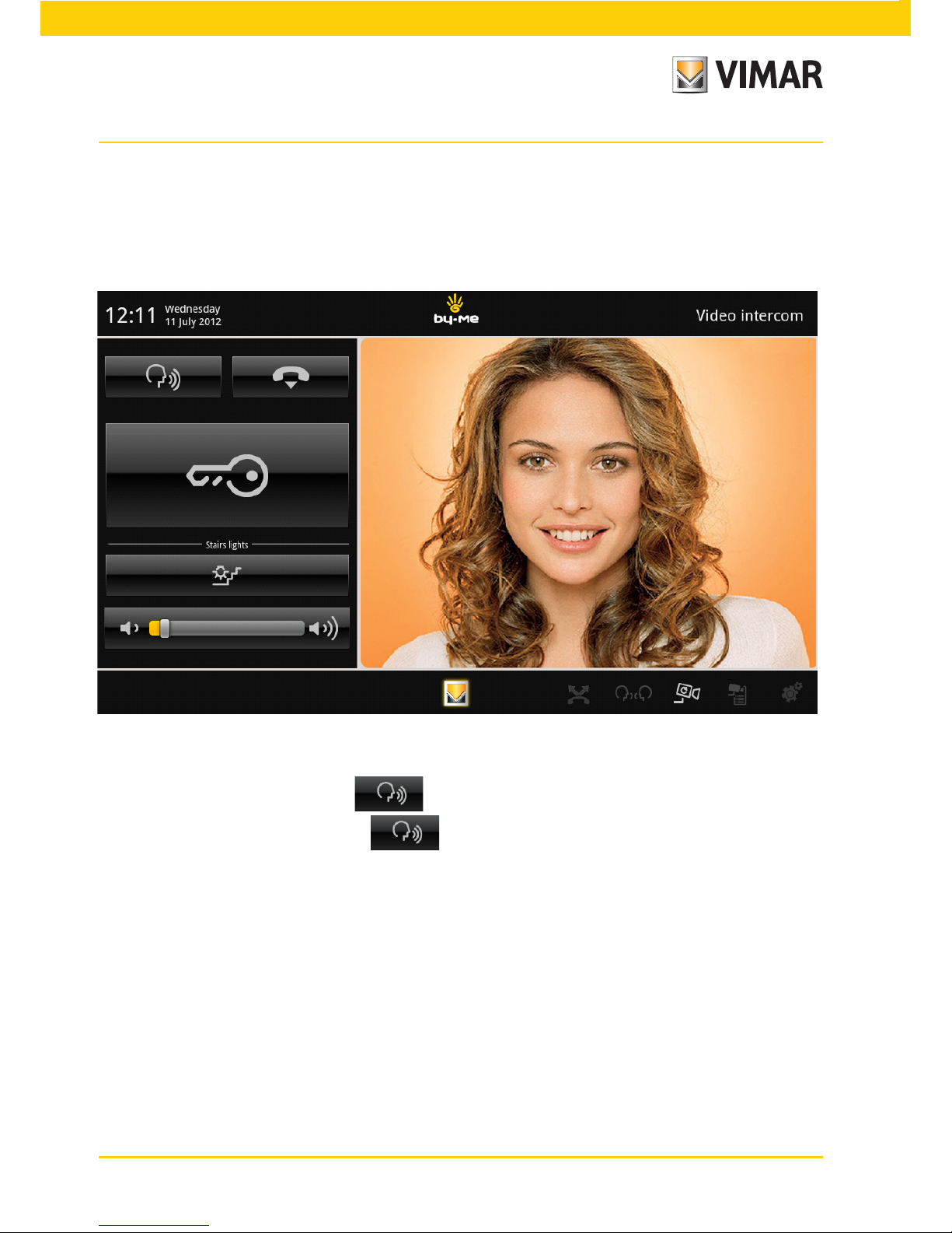
Answering calls.
When a call is made from a speech unit (external panel or consumer unit), the device related to the called numerical
identification modulates the programmed call tone on the speaker; the video door entry unit then emits an audible
warning and, if there is also the video signal (that is, for instance, there is an audio/video panel), the display will
switch on to show the person making the call.
Being a "Handsfree" system (also called On/Off speakerphone), to answer the call and communicate with the
speech unit, it is sufficient to touch the icon.
To break off the communication touch the icon again.
The call time is set as a panel parameter; these parameters can all be set in the phase of programming the
external panel (MASTER) and involve various functions such as timing, recording users, etc. (for a full list of the
parameters please see the technical documentation for the panel used and also read the "PROGRAMMING THE
Due Fili PANEL" chapter).
If the video door entry unit is interfaced with the By-me home automation system, it is possible to end the call
voluntarily.
Video door entry system
Page 25
23
If there are no active calls, the video touch screen will show a window similar to the one shown below.
Self-start function.
This function enables activating audio and video communication on the speech unit without a call being received;
this can be useful, for instance, in the case in which it is wished to check the external zone or an internal zone
where an additional video camera has been installed.
To activate self-starting on the external panel it is necessary to send the SELF-START command.
Repeatedly touching the icon associated with the SELF-START command cyclically performs self-start on any
other secondary panels fitted; the progressive sequence is programmable as a panel parameter (using the PC,
USB 02024 interface and the “EVCom” software.
The self-start on further additional stand-alone video cameras type CCTV (for instance 20560, 14560, 20565,
14565) is constrained by the presence of the audio/video interface 02016.
For greater details see the chapter “AUDIO/VIDEO INTERFACE FOR VIDEO CAMERAS” in this manual.
Conversation Privacy.
The “Conversation Privacy” function enables communicating with the speech unit only if a call has arrived or if a
self-start has been performed; it is not possible to listen to any other communications in progress nor run a selfstart while there a conversation is in progress.
In Two Wire systems the "confidential conversation" function is always enabled.
Video door entry system
Page 26

24
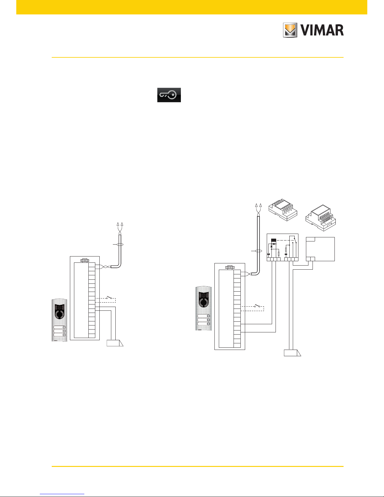
“Door Open” indicator.
This function enables displaying a “Door Open” signal on the video door entry unit through the ignition of an
appropriate icon; this application is useful to avoid unwanted access to the housing unit.
To enable this function it is necessary, when the door is closed to connect a sensor with a N.O. contact to the
terminals ‘PA' and 'M' of the panel of the Two Wire system.
The icon turns on when at least one of the enabled doors closes the contact on the respective panel.
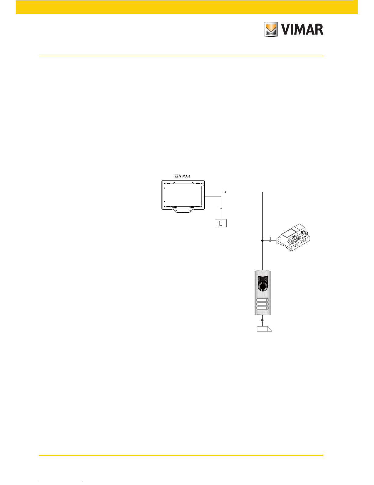
Example of installation:
Video door entry system
Figure 12 - Connection of the “door open” signal with additional power supply.
TE - Video external entrance panel Art. 02003
CP - Lock opening button
SE - Electric lock 12 Vdc
Art. 02037
N.O. door closed
CP
TE
SE
TE
B2
B1
EXT+
EXT-
VLED
X
M
PA
CA
M
S+
S-
+12V
-L
SR
F2
F1
M
1 2
Page 27
25
LOCK command activation.
This command opens the lock of the door or the gate that provides access to the housing unit.
The command is made by touching the icon that sends the LOCK command to the panel which activates the corresponding actuator.
With reference to the Two Wire panel series 0200.. its terminals to be used are the following:
• “S+/S-“ for locks at 12 V dc with low absorption (200 mA max continuous)
• “+12V/SR” for locks with high absorption (specific external relay 12 V dc and dedicated power supply)
The activation time can be programmed as a panel parameter (see the chapter “PROGRAMMING THE TWO WIRE
PANEL); the LOCK command is activated with both the MONITOR ON and OFF.
Example of installation:
Figure 13 - Electrical Lock 12Vdc 200mA max Figure 14 - Electrical Lock 15Vac 2A max
AL - Elvox Power Supply Art. 832/030
TE - Video external entrance panel Art. 02003
RL - Relay Art. 02021
CP - Lock opening button
SE - Electric lock
Art. 02037
CP
TE
SE
B2
B1
EXT+
EXTVLED
X
M
PA
CA
M
S+
S-
+12V
-L
SR
F2
F1
M
1 2
TE
Art. 02037
CP
AL
RL
TE
Art. 02021
Art. 832/030
SE
B2
B1
EXT+
EXT-
VLED
X
M
PA
CA
M
S+
S-
+12V
-L
SR
F2
F1
M
1 2
TE
1 15
PRI
1521C 543RC
+
-
Video door entry system
Page 28

26
Video door entry system
Stair lights control activation (FUNCTION-F1/F2 or AUX SERVICE 1/2).
With this command it is possible to activate the output used for commanding a suitable external relay connected
to one or more lamps to be turned on.
To activate this type of service it is possible to use both the FUNCTION F1/F2 commands (actuators available
directly on the panel and common to all the internal ones) or the AUX 1/2 SERVICE commands (up to a max of
16 independent services) with the support for an external digital relay art. 02022.
The command is activated by touching the appropriate icon that sends the AUX 1 SERVICE command that activates the corresponding output in the supporting digital relay (factory setting); nothing anyhow prohibits using the
F1/F2 FUNCTION command and the related actuator of the panel (use the terminal '+12V' as positive and 'F1' or
'F2' as negative) to enable an external auxiliary relay (to setup).
For loads supplied at 230 V it is recommended to use relays of 12 Vdc with output 230 Vac 3 A.
The staircase lighting command is always active in both states of operation MONITOR OFF and MONITOR ON
respectively.
Example of installation:
Figure 15 - Staircase lighting with F1/F2 FUNCTION
Figura 16 - Staircase lighting with AUX
1/2 SERVICE
AL - Power Supply Art. 02030
RD - Digital relay Art. 02022
RL - Relay Art. 02021
TE - Video external entrance panel Art. 02003
CP - Lock opening button
SE - Electric lock 12 Vdc
Art. 02037
CP
RL RL
TE
Art. 02021 Art. 02021
SE
B2
B1
EXT+
EXTVLED
X
M
PA
CA
M
S+
S-
+12V
-L
SR
F2
F1
M
1 2
TE
1521C 543RC
+
-
1521C 543RC
+
-
Function
F2
Load max
230 V~ 3A
Function
F1
Load max
230 V~ 3A
Art. 02030
0
28V
1
PRI
2 B1 B2
Pillar
1
A B C
B12 B2
1A
ID2
ID1
ID0
2A1B 2B
RD
AL
Art. 02022
Contact N.O.
230 V max 3A
Contact N.O.
230 V max 3A
Entrance panel
Page 29

27
Doorbell calls
This application enables, with a normal N/O button outside and connected directly to the video door entry unit,
accomplishing the function performed by the traditional doorbell.
The N/O button must be connected to the terminals ‘FP' and 'M' of the multimedia video touch screen and, on
pressing this button, the video door entry unit emits an acoustic signal without however turning on the monitor;
the tone of the bell is fixed and cannot be modified.
Example of installation
1
2
21553
CH
1
2
E+
E-
FP
A
B
C
M
+12
CP
TV
VV
Auxiliary Function Activation (Function-F1/F2 or AUX SERVICE 1/2).
The activation command of any auxiliary functions can be used to activate services or external devices such as,
for instance, courtesy lights, automations, etc.
It is possible to use both the FUNCTION F1/F2 commands (using the actuators available directly on the panel and
common to all the internal ones, that have not already been used - e.g. to switch on the stair lights) or the AUX 1/2
SERVICE commands (up to a max of 16 independent services and that are free from other uses) with the support
for an external digital relay art. 02022.
The command is activated by touching the appropiate icon or the combination of buttons that sends the selected
command (see the map of the combinations in 2ndF in chapter “THE SECOND FUNCTION BUTTON (2ndF)” available to send this command); then as regards the supporting relays, the related loads and connection diagrams,
the same considerations apply as above.
The auxiliary function activation command is always active in both states of operation MONITOR OFF and
MONITOR ON respectively.
WARNING: The activation time of the FUNCTION-F1 and FUNCTION-F2 commands is set with the advanced
panel programming; in addition it is possible to set also the activation time of the AUX 1 SERVICES. .16 (for all
the details see the related technical documentation art. 02022).
Figure 17 - Doorbell calls
CP - N/O Call button
VV - Multimedia video touch screen 21553
Video door entry system
Page 30

28
Landing calls.
The system enables making both audio and audio/video external stations that can be used, for instance, on the
landings of condominiums through which people pass to access the door for entry into the apartments.
The audio speech unit is made with the call button 20577 or 14577 while the audio/video one is composed of the
same call button with which a video camera is combined (art. 20560, 14560 or 20565, 14565) with the opportunity
of adding also the LED illuminators (art. 20570, 14570) if the environmental illumination is not enough.
Finally, to make the audio/video call from the landing, it is necessary to use the audio/video interface for video
cameras 02016 (see the chapter "AUDIO/VIDEO COMMUNICATION FOR LANDING CALLS" of this manual).
Example of installation:
Alimentatore
Targa principale
Chiamata Fuori Porta
Audio Video
Montante
Art. 02037
Art. 02037
D
C
B
A
Art. 02037
20577/14577
CH
1
2
E+
EFP
A
B
C
M
+12
2
+12
S
1
0
28V
1
PRI
2 B1 B2
AL
CP
Art. 02030
1 2
BUS D BUS P
1 12 2
SP
NT
Art. 02020
A
B
C
A
V
TV
21553
VV
Video door entry system
Loading calls
Audio Video
Power supply
Entrance panel
Pilar
Figure 18 - Landing calls, audio only
AL - Power Supply Art. 02030
SP - Separator Art. 02020
CP - Landing call button Art. 20577/14577
NT - Network
VV - Multimedia video touch screen 21553
Page 31

29
Alimentatore
Targa principale
Chiamata Fuori Porta
Audio Video
Montante
Art. 02037
Art. 02037
D
C
B
A
Art. 02037
20577/14577
CH
1
2
E+
EFP
A
B
C
M
+12
2
+12
S
1
0
28V
1
PRI
2 B1 B2
AL1
NT
CP
TC
Art. 02030
V3 MV3 MV4A3 A4V4MA3 MA4
1 2
BUS D BUS P
1 12 2
SP
NT
Art. 02020
20565/14565
+T
V
M
.
6
7
A
PROGRAM EXPANSION MODULE
B C
V1 MV1 MV2A1 A2V2MA1 MA2
EXT F2 +IF1 B2GND+12V B1
- +U +I A B C D
PRI
AL2
Art. 02032
IF
Art. 02016
TV
A
B
C
A
V
21553
VV
Loading calls
Audio Video
Power supply
Entrance panel
Pilar
Figure 19 - Landing calls, audio/video
For further details on the connections, see the technical documentation of the single articles (call button, video
cameras, etc.) and the related diagrams given therein.
AL1 - Power Supply Art. 02030
AL2 - Power Supply Art. 02032
IF - Audio/video interface for video cameras Art. 02016
SP - Separator Art. 02020
CP - Landing call button Art. 20577/14577
TC - Video camera with microphone Art. 20565/14565
VV - Multimedia video touch screen 21553
NT - Network
Video door entry system
Page 32
30
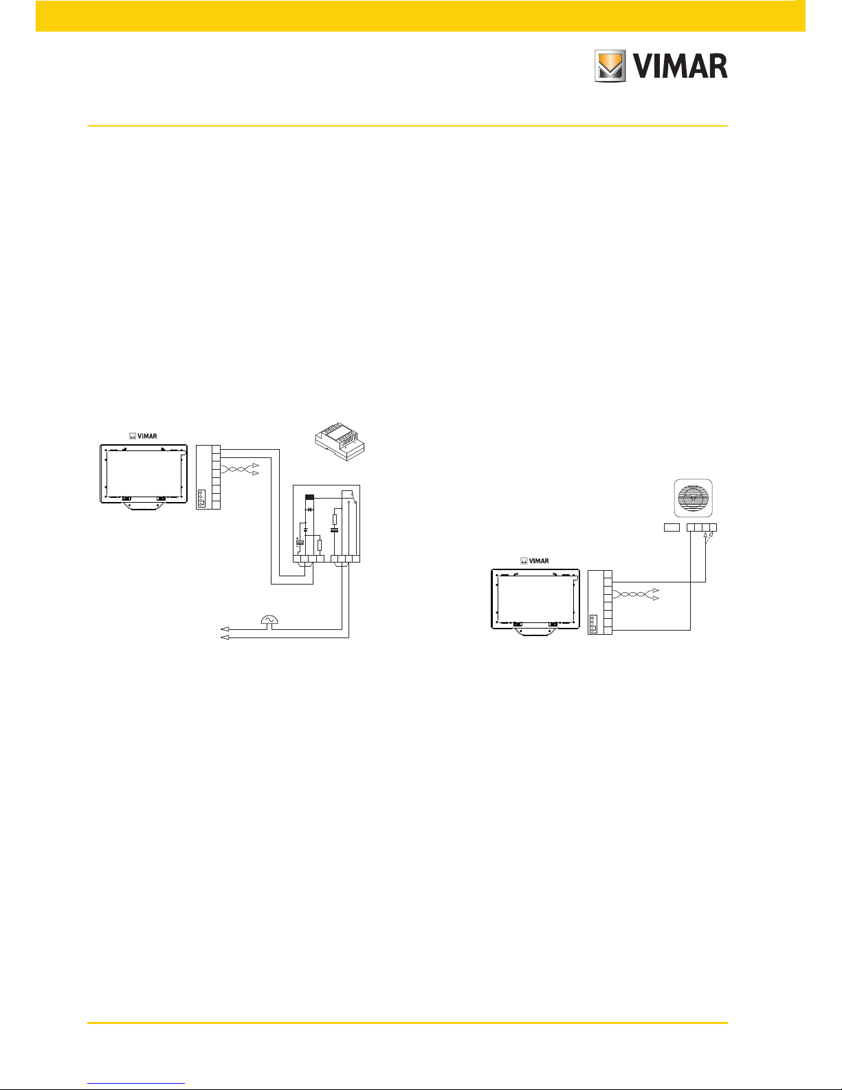
Installation of supplementary external ringtones.
If it is necessary to transmit the call audible warning to different points of the system (large properties, etc.) or boost
its intensity, it is possible to install external bell repeaters.
To do this, uses the terminals '+12' and 'CH' in the case of ringtones that need an external relay at 12 Vcc (for
instance art. 02021) while, if the Elvox bell 860A powered by the mains is used, the terminals to wire are 'CH'
and 'M'.
N.B.: It is necessary not to exceed the absorption of 100 mA from the output '+12' so as not to cause any malfunctioning of the video door entry unit.
Examples of installation:
ideo door entry units with simultaneous video calls.
The need to install multiple video door entry units in parallel, with the simultaneous activation of the LCD monitors,
has requirements tied to their consumption of current that must be limited so as not to exceed the permissible
delivery of the main power supply 02030.
In the phase of configuration it is possible to set “call groups” (that are groups of video door entry units that at
the same time answer the same call) in two different modes that can be set via advanced programming with PC
and the USB 02024 interface with “EVCom” software (for the details see chapter "CONFIGURATION OF THE
OPTIONAL FUNCTIONS OF THE VIDEO DOOR ENTRY UNIT"); these modes are:
1. Group call with only the master active at the call (so only the master video door entry unit is switched on).
2.
Group call with all the group video door entry units active at the call (all the video door entry units are switched
on).
SS
1
2
Art. 02021
CH
1
2
E+
E-
FP
A
B
C
M
+12
AR
RL
C 1 2 15 RC 3 4 5
21553
VV
1
2
CH
1
2
E+
E-
FP
A
B
C
M
+12
PRI 4 5 7 8
NT
SN
Art. 860A
21553
VV
RL - Relay Art. 02021
SN - Elvox bell Art. 860A
AR - Bell power supply
NT - Network
SS - Additional ringtone
VV - Multimedia video touch screen 21553
Figure 20 - External bell installation with relay
Figure 21 - Installation with Elvox
Video door entry system
Page 33
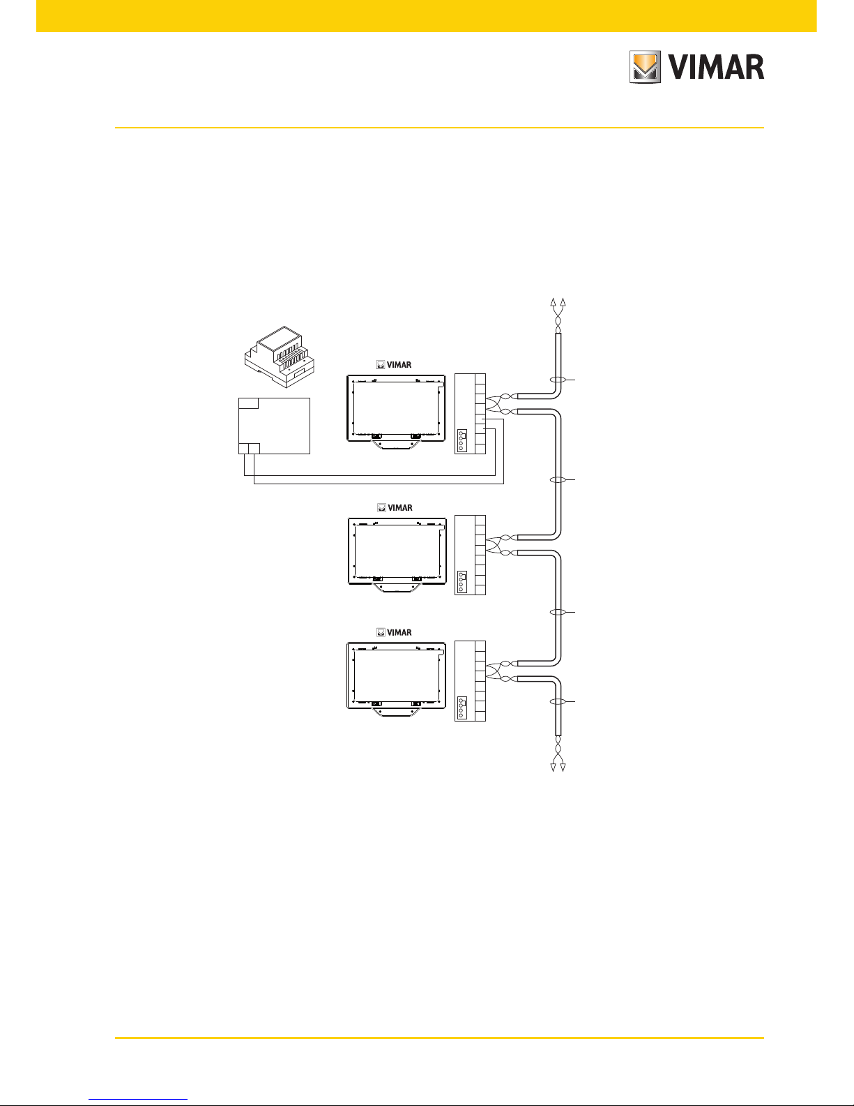
31
Note: In the second mode of operation, it is necessary to set up an additional power supply 02031 for each
added video door entry unit (after the first two) in a call group so as to guarantee the correct current absorption
from the main power supply.
Example of installation:
Cavo
All’Alimentatore
Art. 02037
CH
1
1 2
2
E+
E-
FP
A
B
C
M
+12
1 2
Art. 02037
Art. 02037
Art. 02037
CH
1
2
E+
E-
FP
A
B
C
M
+12
AL2
CH
1
2
E+
E-
FP
A
B
C
M
+12
PRI
AL1
NT
M
Art. 02031
Art. 02030
- +U
21553
VV
21553
VV
21553
VV
Figure 22 - Video door entry units with simultaneous video calls
AL1 - Power Supply Art. 02031
AL2 - Power Supply Art. 02030
M - Pillar
NT - Network
VV - Multimedia video touch screen 21553
Power supply
Video door entry system
Page 34
32
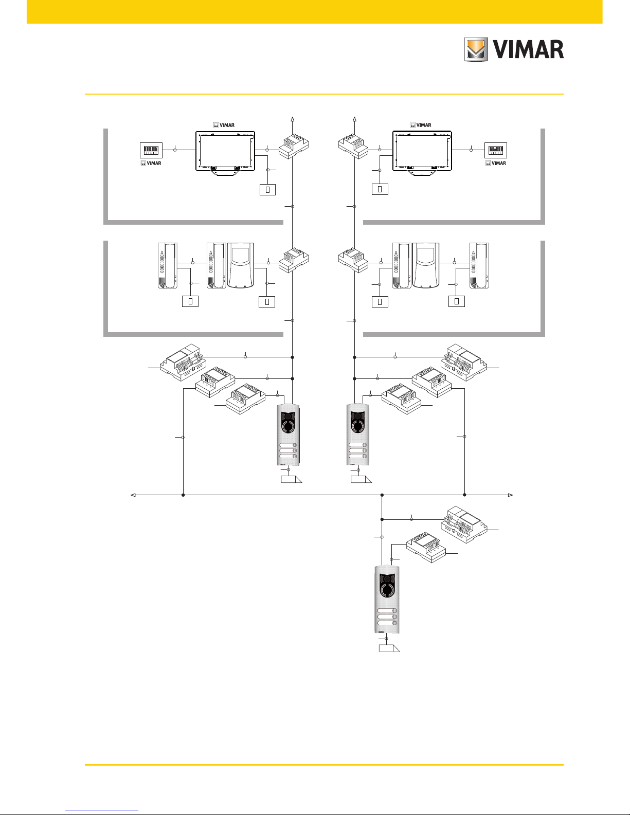
Installation topology.
In practice there are different installation topologies for creating video door entry systems; the type of each system
in fact depends on the structure of the property, the number of outdoor and indoor stations that is desired to be
installed and the functions to be enabled.
The most recurrent diagrams are typically those where there is one or more outdoor calling stations and one
or more indoor answering stations. These outlines then differ according to the functions and services required
(connection of a number of video door entry units in parallel, bell repeaters, actuators for external services, etc.)
for which it is necessary to introduce specific supplementary modules (supplementary power supplies, external
relays, etc.).
Examples:
TE
SE
AL
K
2
2
2
2
21553
VV
Video door entry system
Figure 23 - Video door entry system 2 indoor stations
AL - Power Supply Art. 02030
TE - Video external entrance panel Art. 02003
K - Landing call button
SE - Electric lock 12 Vdc
VV - Multimedia video touch screen 21553
Page 35
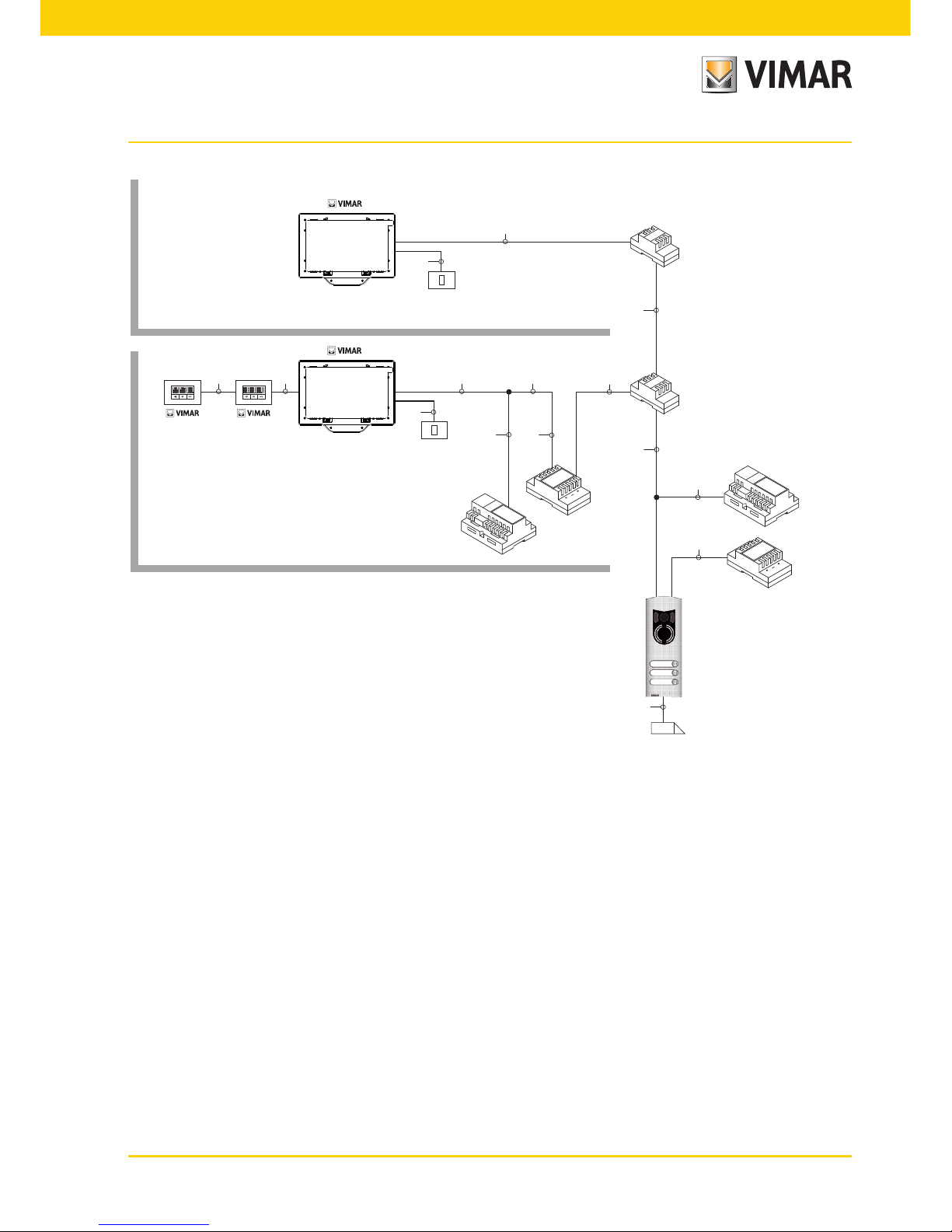
33
In the above examples, there is a single main power supply (AL) in the systems that use the single outdoor station
(TE); in the case in which, it is necessary to build a network of intercommunicating audio/video door entry units
isolated from the main system, in the case in which there are several external sources of audio-video signal (outdoor stations with video camera and voice unit) or you want to create separated communication sectors or in the
case of systems installed in a building complex, it is necessary to insert further supplementary modules such as:
• concentrators (CC);
• additional power supplies (AL1 and AS);
• separators (SP).
Appartamento 1
Appartamento 2
20557/14557
TE
AS
AL
AL
SP
DV
DV
K
K
VV
CV CV
SE
20557/14557
2
2
2
2 2
2
2
2
2
2
2
2
2
2
2
21553
VV
21553
Flat 1
Flat 2
Figure 24 - Video door entry system multi-family
AL - Power Supply Art. 02030
AS - Additional power Supply Art. 02032 for LED power supply
DV - Video distributor Art. 682D
SP - Separator Art. 02020
TE - Video external entrance panel Art. 02003
SE - Electric lock 12 Vdc
K - Landing call button
CV - Audio Door Entry Unit Art. 20557/14557
VV - Multimedia video touch screen 21553
Video door entry system
Page 36
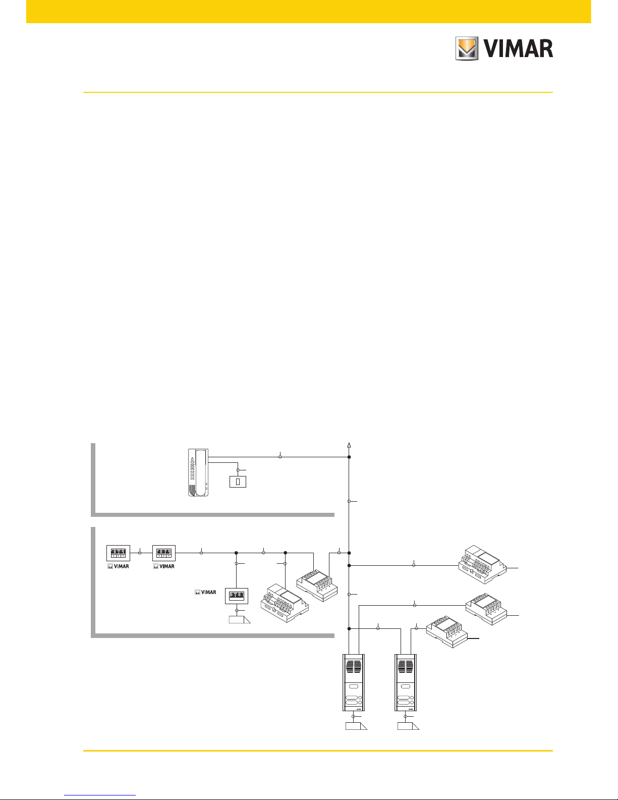
34
In the system pillar there can be installed both Vimar and Elvox (VV, VE, CE) indoor stations, provided that these
belong solely to the Two Wire system range.
For the technical details on the possible installation topologies both in the standard residential sector and in the
building structure complex, see the examples given in the attached diagrams “INSTALLATION EXAMPLES AND
DIAGRAMS” or the Two Wire technical diagrams.
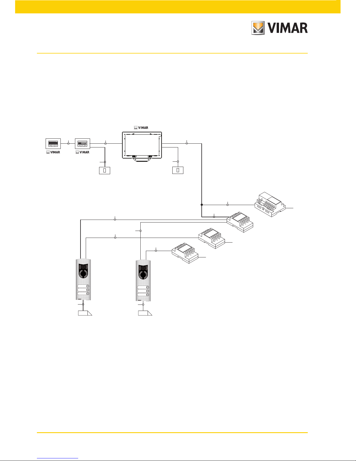
Examples:
20577/14577
K
CV CV
20577/14577
K
AL2
CC
AL1
AL2
SE
SE
TE TE
~
~
~
2
2
2
2
2
2
2
2
2
2
2
2
2
21553
VV
Video door entry system
Figure 25 - Video door entry system 2 outdoor stations
AL1 - Power Supply Art. 02030
AL2 - Power Supply Art. 02031
CC - Relay Art. 02019
TE - Video external entrance panel Art. 02003
K - Landing call button
CV - Audio Door Entry Unit Art. 20557/14557
SE - Electric lock 12 Vdc
VV - Multimedia video touch screen 21553
Page 37
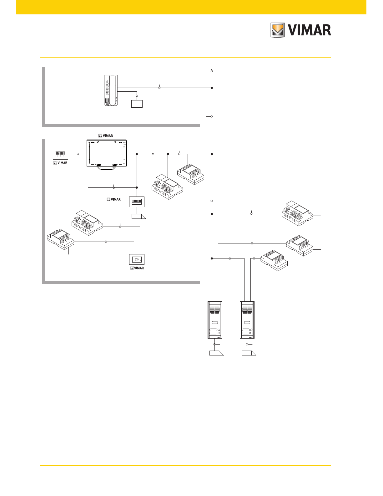
35
Appartamento 1
VV VV
SE
20557/14557
CV
ALAL
SPSP
ASAS
TE TE
20557/14557
CV
Appartamento 2
Appartamento 1 Appartamento 2
TE
AS
AL
SE
SE
K
DV DV
DV DV
CECE VEVE
~
~~
~
~
~
K
K
K
K
K
2 2
2
2
2
2
2 2
2
2
2
2
2 2
2
2 2
2
2
2
2
2
2
2
2
2 2
2
2
2
2
2
21553
21553
Figure 26 - Video door entry system in building complex
AL - Power Supply Art. 02030
AS - Additional power Supply Art. 02032 for LED power supply
CE - Elvox Audio Door Entry Unit Art. 6209
DV - Video distributor Art. 682D
SP - Separator Art. 02020
TE - Video external entrance panel Art. 02003
VE - Elvox Video Door Entry Unit
Art. 6309, 6309/C, 6009+6209+6145, 6009/C+6200+6145
K - Landing call button
SE - Electric lock 12 Vdc
CV - Audio Door Entry Unit Art. 20557/14557
VV - Multimedia video touch screen 21553
Video door entry system
Page 38

36
Configuration of the video door entry unit.
All the main standard functions of the video door entry unit seen in the chapter “FUNCTIONS OF THE VIDEO
DOOR ENTRY UNIT” are configured with the buttons on the front of the device (see fig. 6); for the advanced
programming of the video door entry unit (optional functions such as setting groups, association of buttons with
specific commands, configuration of the intercom calls, association with the landing audio/video call buttons, etc.)
it is necessary to use the PC and the USB 02024 interface and the “EVCom” software.
Configuration of the standard functions of the video door entry unit.
Configuration of the standard functions of the video door entry unit enables satisfying the application requirements
of most of the systems that are installed. According to the state of operation of the monitor (ON or OFF) it is possible to set and program different functions that are as follows.
Enabling the self-start function.
To use this function it is necessary to configure the panel so that it is enabled to receive the self-start command
(see the panel parameters in the Two Wire documentation - parameter enabled by default).
WITH THE MONITOR ON, sending the self-start command allows sequential viewing of the images sent from the
video cameras of the video panels present besides the main one (it is necessary to set the self-start sequence on
the MASTER panel with the PC and the USB 02024 interface with “EVCom” software).
Enabling the “User Away” function.
This type of function allows the user, via the external panel, to signal his own absence to the guard room consumer
unit (if applicable); it can moreover be used also in the case in which the user is at home but doesn’t want to be
disturbed. When the function is enabled the video door entry unit that receives the call doesn't emit any audible
warning and it doesn't turn on the monitor.
Audio/video communication for landing calls.
If there is the need to install one or more indoor audio/video call stations (“landing call”), there are two different
types:
- landing calls, “audio only";
- landing calls, “audio/video”.
According to the chosen type, the installation of modules and auxiliary accessories is necessary.
Landing calls, audio only.
If there is a speech unit on the landing with only the audio function (art. 20577 or 14577), the video door entry unit
must be configured for being able to receive the audio communication from the landing call button.
To associate the landing call button with the video door entry unit carry out the following procedure:
1. Code the landing call button (see the instructions sheet of art. 20577 or 14577)
2. Associate the video door entry unit/audio door entry unit with the landing call button 20577/14577 using the PC
and the USB 02024 interface with “EVCom” software (see the chapter “CONFIGURATION OF THE OPTIONAL
FUNCTIONS OF THE VIDEO ENTRYPHONE” - Association of the landing calls) of this manual.
NOTE: To associate the video/audio door entry unit with the landing call solely of the audio type it is necessary to
keep the call type selection jumper (set on the removable terminal side of 20577/14577) in position “A.”
Video door entry system
Page 39
37
Landing calls, audio/video.
If there is a speech unit on the landing with the audio/video function (art. 20577/14577 with 20560/14560 or
20565/14565), the video door entry unit must be configured for being able to receive the audio communication
from the call button 20577/14577 and activation of the video camera from the landing.
To activate the video camera on the landing it is necessary to install the audio/video interface for video
cameras art. 02016.
To associate the landing call button with the video door entry unit carry out the following procedure:
1. Code the landing call button (see the instructions sheet of art. 20577 or 14577)
2. Associate the video door entry unit/audio door entry unit with the landing call button 20577/14577 using the PC
and the USB 02024 interface with “EVCom” software (see the chapter “CONFIGURATION OF THE OPTIONAL
FUNCTIONS OF THE VIDEO ENTRYPHONE” - Association of the landing calls) of this manual.
NOTE: To associate the video/audio door entry unit with the landing call of the audio/video type it is necessary to
keep the call type selection jumper (set on the removable terminal side of 20577/14577) in position “V”.
IMPORTANT: The video/audio door entry unit can be associated with up to a maximum of 4 different
landing call buttons; the identification code of the call button belongs to the class of the monitors (numerical
code from 1 to 200).
The local lock activation time (the default setting is equal to 1 s) can be modified only with the PC and the serial
USB 02024 interface and the “EVCom” software (selection interval from 0 to 250 s).
Vice versa, the response time (30 s), conversation time (300 s) and self-start time (30 s) are fixed and are not
modifiable.
Examples of different types of landing call:
SE
Appartamento 1
20557/14557
TA
AS
AS
AL
AL
SP
CE
CV CV
SE
20557/14557
TA
SE
Appartamento 2
~
~
~
K
2
2
2
2
2 2
2
2 2
2 2
2
2
2
2
2 2
20577/14577
CP
Figure 27 - Landing calls, audio only
Flat 2
Flat 1
Video door entry system
Page 40
38
SE
Appartamento 1
20577/14577
TA
AS
AS
AL
AL
IF
SP
K
CP
TC
CE
VV
CV
SE
20557/14557
TA
SE
Appartamento 2
~
AS
~
~
~
20565/14565
2
2
2
2
2
2
2
2
2
2 2
2
2
2
2
2
21553
AL - Power Supply Art. 02030
AS - Additional power Supply Art. 02032
CE - Audio Door Entry Unit Art. 6209
SP - Separator Art. 02020
TA - Audio external entrance panel Art. 89F3/..., 89F4
IF - Audio/video interface for video cameras Art. 02016
CP - Landing call button Art. 20577/14577
K - Landing call button
CV - Audio Door Entry Unit Art. 20557/14557
SE - Electric lock 12 Vdc
TC - Video Camera Art. 20560/20565
VV - Video Door Entry Unit Art. 20550 + 01963
Figure 28 - Landing calls, audio/video
Flat 2
Flat 1
Video door entry system
Page 41
39
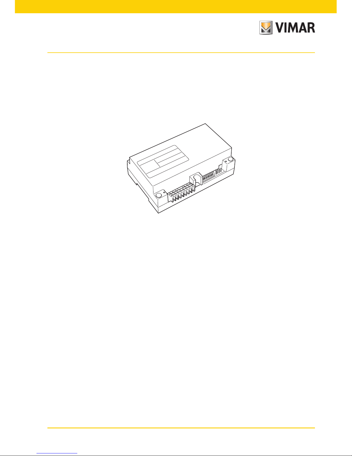
Audio/video interface for video cameras.
The audio/video interface for video cameras art. 02016 is a DIN bar 8-module device necessary to make both the
audio/video landing call and self-start any additional video cameras installed in the system with “CCTV function.”
The device is able to manage 4 video cameras directly with the related audio inputs (video cameras 20565 and
14565) and up to a maximum of 16 video cameras with related audio inputs using special expansion modules
with 4 inputs art. 02017.
The interface can be identified in the same way as a SLAVE panel, with a numerical code between 2 and 15 and
different from that of any other panels present in the system; alternatively it can be used without numerical identification associating it with the landing call.
If it is identified as a SLAVE panel it is possible to self-start sequentially viewing the video cameras connected
directly or through expansion modules (maximum 16 video cameras).
Whereas if the interface is not identified but only associated with the landing call button 20577 or 14577, the video
cameras corresponding to the calls sent from the landing buttons (maximum 4 landing calls with the related video
camera) can be turned on and self-start is also possible on the various video cameras connected to the interface
making a fictitious intercom call toward the call button.
APPLICATIONS:
1. Using the interface 02016 for additional video cameras (“CCTV” function).
If it is wished to use the audio/video interface for video cameras 02016 for controlling the self-start of additional
video cameras in the system (with any audio signal and up to a maximum of 16 video cameras using the special
expansion modules art. 02017), it is necessary to code the interface 02016 only with PC and USB 02024 interface
and the “EVCom” software assigning an identification code between 2 and 15 (numbering dedicated to the SLAVE
panels) different to that of the other panels in the system (for greater details see the technical documentation for
art. 02016).
Video door entry system
Page 42

40
In this way the interface behaves exactly as a normal SLAVE panel; to switch on the first video camera it is necessary to repeatedly send the SELF-START command from the video door entry unit (see the chapter “SELF-START
FUNCTION“) so as to “scroll” through any panels present to reach the first video camera connected to the 02016.
N.B.: For each video door entry unit it is possible to configure the self-start sequence of the additional video cameras connected to the audio/video interface 02016; this configuration can be made exclusively with advanced
programming of the audio/video interface by using the PC and the USB 02024 interface with “EVCom”
software (see the related technical documentation).
1 2
- +U
V
M
+I A B C D
PRI
NT
Art. 02032
PA
TV
TV
SE
B2
B1
EXT+
EXTVLED
X
M
PA
CA
M
S+
S-
+12V
-L
SR
F2
F1
M
T+
- +U
V
M
+I A B C D
PRI
NT
Art. 02032
T+
- +U
V
M
+I A B C D
PRI
NTNT
Art. 02032
T+
- +U
V
M
+I A B C D
PRI
TC TC
TC
TC
AL AL AL AL
Art. 02032
T+
0
28V
1
PRI
2 B1 B2
AL
Art. 02030
IF
Art. 02016
NT
SP
V3 MV3 MV4A3 A4V4MA3 MA4
A
PROGRAM EXPANSION MODULE
B C
V1 MV1 MV2A1 A2V2MA1 MA2
EXT F2 +IF1 B2GND+12V B1
1A
–
+
2A 1B 2B 1C 1D2C 2D
1 2 1 2 1 12 2
Art. 02019
Video door entry system
AL - Power Supply Art. 02030
IF - Interface for four video cameras with audio Art. 02016
SP - Separator Art. 02019
TV - Video external entrance panel Art. 02003
NT - Network
PA - Door opening command
SE - Electric lock 12 Vdc
TC - CCTV video camera 12 Vdc
Figure 30 - Example of installation of additional video cameras
Page 43

41
2. Use of the interface 02016 for audio/video landing calls.
If there is a landing audio/video speech unit (push-button 20577/14577 and video cameras 20560, 20565, 14560,
14565), the audio/video interface can be used instead without numerical coding of the secondary panel as instead
was necessary in the preceding case (in this way an ID reserved for the class of panels is not pointlessly occupied).
WARNING: The association between landing call button (20577 or 14577) and the video/audio door entry
unit to be called can be done via advanced programming as the association of the video camera with the
audio/video interface for video cameras (02016); then it is necessary to use the PC and the USB 02024
interface with “EVCom” software (see the related technical documentation).
On sending the audio/video call by pressing the landing nameplate button (art. 20577 or 14577), the interface will
enable the video camera associated with it.
With this type of configuration it is possible to connect up to 4 video cameras for the 4 possible landing call
buttons.
NOTE:
It is possible to self-start the video camera associated with the landing call button (and if necessary in sequence on
the following ones) by sending an intercom call toward the latter; it is therefore necessary to configure the video
door entry unit so it can send this command (see the chapter “PUSH-BUTTON CONFIGURATION - Intercom calls").
Repeatedly sending the command allows “scrolling” through all the video cameras connected to the video interface 02016.
Video door entry system
Page 44

42
Ringtone type selection.
Using the multimedia video touch screen it is possible to select the types of ringtone to combine with the different
calls that it can receive:
- call from panel (video door entry unit);
- call from landing (audio door entry unit);
- intercom call (Interphone).
In the main window touch the icon and subsequently the icon.
Video door entry system
The ringtone must be set by selecting the one you want from a predefined list of ringtones; alternatively to these
it is possible to upload mp3 files.
• Touch the icon to set the ringtone associated with the call from the panel.
• Touch the icon to see the list of default ringtones and touch the one you want.
Page 45

43
• Touch the icon to confirm the selection made.
• Touch the icon to set the ringtone associated with the call from the landing.
• Touch the icon to see the list of default ringtones and touch the one you want.
• Touch the icon to confirm the selection made.
• Touch the icon to set the ringtone associated with the intercom call.
• Touch the icon to see the list of default ringtones and touch the one you want.
• Touch the icon to confirm the selection made.
If you want to associate an mp3 file (previously uploaded to the multimedia video touch screen via the USB or
SHDC port) with the ringtone, it is sufficient to touch the icon and select the desired file.
Video door entry system
Page 46

44
Associating the secondary functions.
This window defines the buttons you can associate with the functions F1, F2, AUX1, …AUX16.
• In the main window touch the icon and then the icon.
• View the list of functions.
For each button it is necessary to set:
1. associated function (F1....AUX16);
2. parameter;
3. wording associated with the button (for example what is controlled);
4. icon associated with the button.
• Touch the icon to confirm the selection made.
Video door entry system
Ringtone volume adjustment.
The volumes of the ringtones described above are unmistakeably adjusted in a similar manner for all the types of
call (from external panel, landing or intercom).
Touch the cursor of the scroll bar and move it to the left or to the right according to the desired volume (the level
is highlighted by the illumination of the bar).
Page 47

45
Each button will activate the relevant command.
The position of one button in relation to the others depends only on where it is located in the creation list; this
position can be changed by means of the and icons.
Finally, the icon enables deleting the corresponding button.
Video door entry system
Page 48
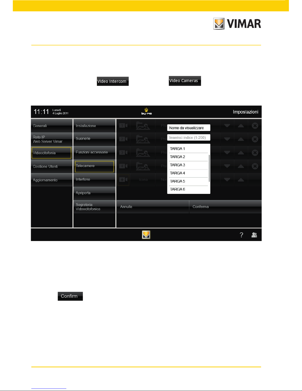
46
Video Cameras.
With this option you define the activation mode for the video cameras installed in the system and the buttons
for direct access to the video cameras.
• In the main window touch the icon and then the icon.
• View the list of video cameras.
For each button it is necessary to set:
1. ID of the panel (MASTER panel, panel 2 … 15);
2. video camera index (1 … 16);
3. text associated with the button (for example the room where the video camera is installed);
4. icon associated with the button.
• Touch the icon to confirm the selection made.
Video door entry system
Page 49
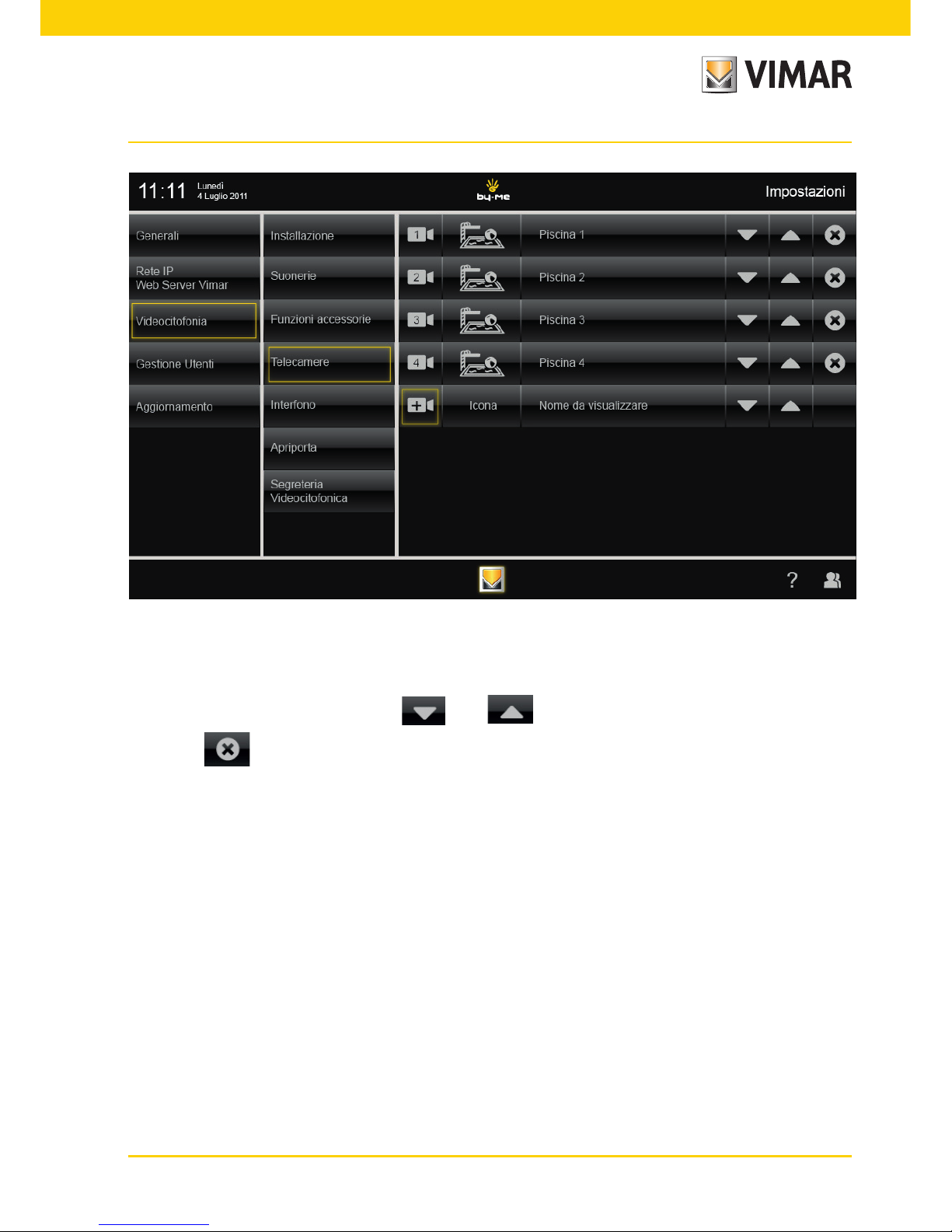
47
Each button will activate the relevant video camera.
The position of one button in relation to the others depends only on where it is located in the creation list; this
position can be changed by means of the and icons.
Finally, the icon enables deleting the corresponding button.
Video door entry system
Page 50
48
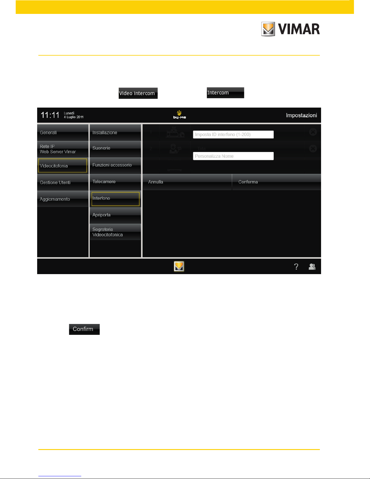
Intercommunications.
With this option you defined the buttons for making the intercom calls and talking with the speaker.
• In the main window touch the icon and then the icon.
For each button it is necessary to set:
1. recipient of the call (ID: 1..200);
2. text associated with the button (for example the room where the indoor station is installed);
3. icon associated with the button.
• Touch the icon to confirm the selection made.
Video door entry system
Page 51

49
Each button will activate the relevant intercom call and the communication between the speakers.
The position of one button in relation to the others depends only on where it is located in the creation list; this
position can be changed by means of the and icons.
Finally, the icon enables deleting the corresponding button.
Video door entry system
Page 52

50
Door Opening.
With this option you define the behaviour of the door opening button (icon ).
During a call, the lock associated with this icon is always the one related to the indoor station from which
the call is being made.
When there is no call in progress it is possible to select the behaviour of the button by setting one of the following
options:
1. The associated lock is that of the last call received (default behaviour).
2. The associated lock is the one defined in the phase of configuration.
In this section it must therefore be possible to enable option 2 and specify the associated ID (panel1, …,
panel15, 1, …, 200).
• In the main window touch the icon and then the icon.
Setting the operation of the icon with a call in progress:
1. door opening (default);
2. door opening and ending the call.
Video door entry system
Page 53

51
Video door entry system answering machine.
With this option you define the timeout at the end of which the video door entry system answering machine starts
recording images and sound.
• In the main window touch the icon and then the icon.
Set the answer time by entering a value in the shown range.
Video door entry system recording is set as follows:
- timeout starts with the call request;
- at the end of the timeout, if the user has not answered, the video door entry system answering machine function
is started.
Video door entry system
Page 54
52
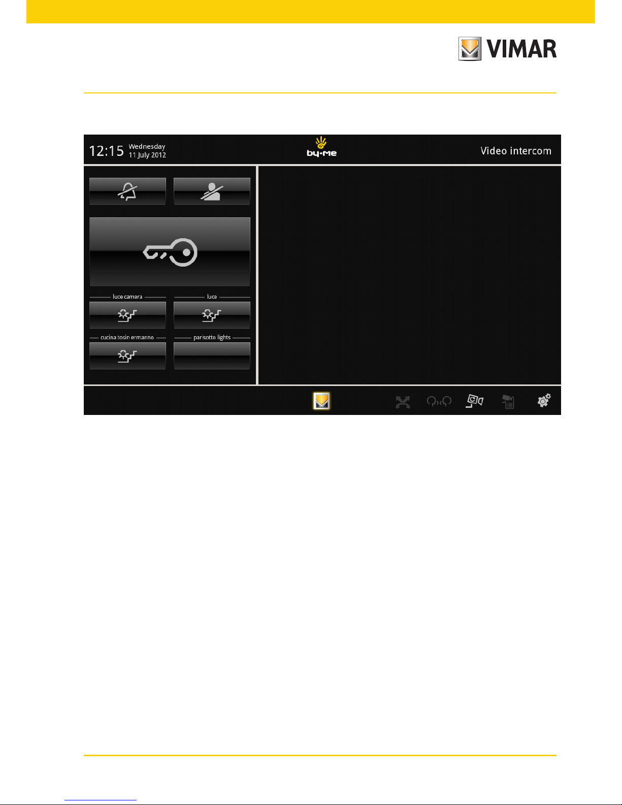
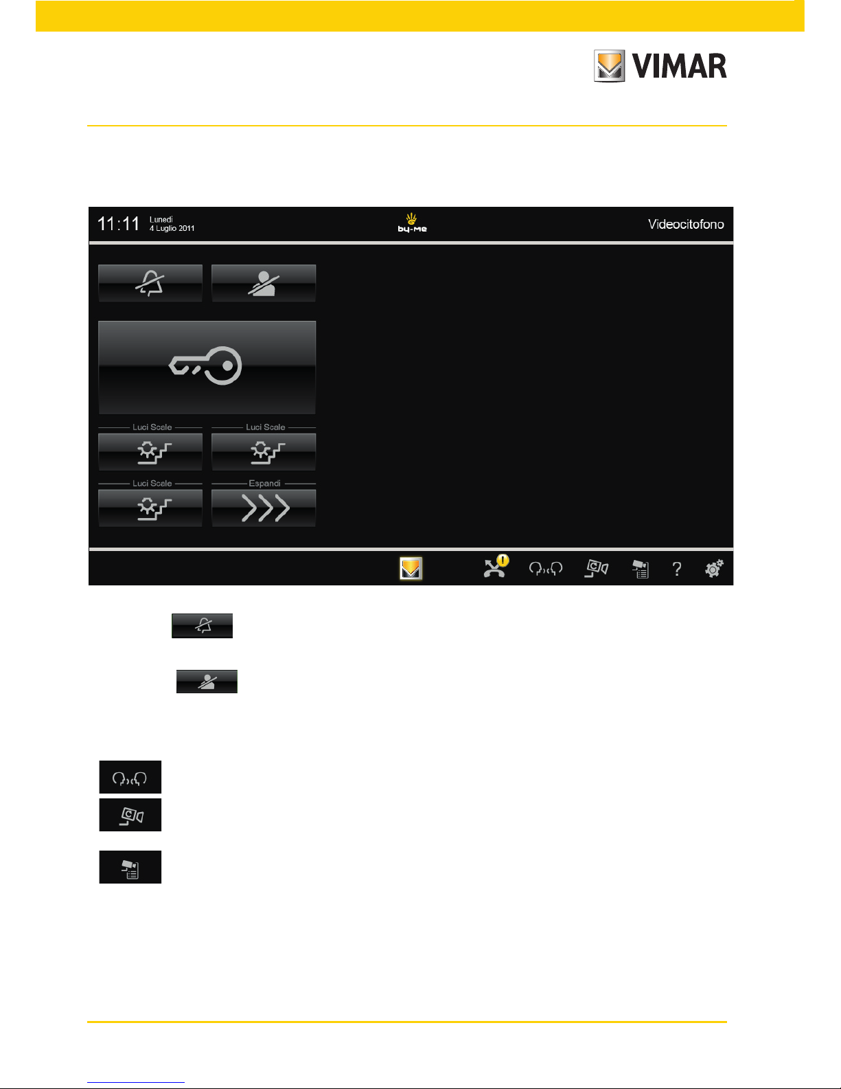
Video door entry unit with no active calls.
If there are no active calls the video touch screen will show a window more or less similar to the one below.
• Touching the icon disables the internal ringtone and on the right of the title bar the "ringtone disabled"
icon is displayed.
• Touching the icon disables the "User absent" function and on the right of the title bar the "User
absent" icon is displayed.
Finally, at bottom right there are the following icons:
- to view the icons associated with the intercom calls configured in the system.
- to cyclically view the images transmitted from the video cameras (each touch changes video
camera).
- to view a list of configured video cameras.
Video door entry system
Page 55

53
Icon signaling the title bar.
Next to the title bar can be found on the right, up to three icons of signal:
- “Ringtone disabled"
- “User Away”;
- “Open door”.
Configuration of the functions associated with icons (INTERCOM CALLS).
The icons on the multimedia video touch screen can be configured for sending different specific commands on the bus.
They can be configured, for instance, for sending FUNCTION F1/F2 commands, the self-start command on a specific
panel, the command for making an intercom call, etc…
For example:
1. Set the push-button for intercom calls: on the audio/video door entry unit that you want to call, press any
button (except the hands-free answer button - preferably the LOCK or AUXILIARY SERVICE button) to send the
code of the called device to the calling video door entry unit. The video door entry unit responds to programming with an audible warning.
2. Set the button for sending the FUNCTION F1(F2): using a device that is able to do it (for instance audio/
video door entry units already configured, panels, USB 02024 interface for PC “EVCom” software), send the
FUNCTION F1(F2) command on the bus. The video door entry unit responds to programming with an audible
warning.
3. Set the button as self-start on a specific panel: from the panel on which you want the self-start with the
button being configured, send a call with the button corresponding to the video door entry unit; this responds
to programming with an audible warning.
4. Other functions: they can be programmed entirely in a similar way to the preceding ones.
Video door entry system
Page 56
54
Video door entry system
Setting the flags.
The flags are options that can be turned on/off and affect the behaviour of the video door entry unit; access to the
configuration of the flags is made exclusively with the USB 02024 interface for PC “EVCom”software.
The flags that can be set are given in the following table:
Centralino Enables control via the consumer unit
G3 solo Est. Enables Group 3 only for external calls from panel
G4 solo Int. Enables Group 4 only for intercom calls
Non RIPCH IC Disables call repetition for the intercom
G1 solo Est. Enables Group 1 only for external calls from panel
G2 solo Int. Enables Group 2 only for intercom calls
Grp. Escl. S. If on “User Away,” the secondary ones ring all the same
I.C. Illim. Unlimited duration of intercom conversations
Setting the group calls.
Besides directly setting the secondary identification code (see the chapter "SECONDARY NUMERICAL CODING
OF THE VIDEO DOOR ENTRY UNIT" of this manual) that enables inserting the video door entry unit in a group
of devices (audio/video door entry units) that at the same time receive a call, this association can also be made
via advanced programming with USB 02024 interface for PC “EVCom” software. There are four possible different
groups (G1,G2,G3 and G4); each device can be associated with the single group by indicating (in the specific field
that can be filled in with the aforesaid instruments for advanced programming) the identification code of the master.
Associating landing calls.
Via advanced programming with the USB 02024 interface per PC and “EVCom” software, it is possible (in the
specific field that can be filled in with the above-mentioned instruments for advanced programming) to set the
landing call buttons from which the video door entry unit is able to receive a call.
Each video door entry unit can receive calls up to a maximum of 4 different landing call buttons.
Page 57

55
3.3.1 CONFIGURATION RESET.
This procedure is recommended if you want to modify the ID of a video door entry unit previously programmed
and without keeping the programming for operation of the device.
• In the main window touch the icon and subsequently the icon.
• Finally touch the icon to reset the video door entry unit.
Programming the Two Wire.
WARNING! The following operations must be carried out after powering up the system and before pro-
gramming the audio door entry units and video door entry units.
In the same system there must be only one MASTER panel (identification code 1) while any secondary
panels must be set as SLAVES (see the technical documentation related to the particular panel used).
Do the programming of the panels powering only one panel at a time; the master panel must always be
programmed last.
The configuration of the panel parameters can be done in three different ways:
• Directly from the panel itself using the alphanumeric keyboard or with single buttons.
• With PC and USB 02024 interface and “EVCom” software.
This section will illustrate solely the method of programming with the alphanumerical keypad on the front of the
Two Wire panel; for configuration with the PC see the related technical documentation.
To access the panel configuration menu carry out the following operations:
• Press buttons and at the same time.
• Enter the password to access programming; key in “654321” for the first configuration (default password set by
the factory that must then be modified by the installer).
• Press the button to confirm.
Once in programming mode, use the and push-buttons , and to select the parameters, the push-
button to confirm changes, and the push-button to confirm changes.
At this stage it is possible to scroll through the list of all the panel parameters and the related set values; for each
of these it is possible to enter a value that identifies the parameter and the related configuration.
The set values must be within a certain range (maximum value - minimum value) according to the parameters table
attached to the technical documentation of the panel (see, for instance, the table of “TECHNICAL PARAMETERS
OF THE PANEL” illustrated on the following pages).
For the configuration of the Two Wire panels without the alphanumerical keypad, see the related technical documentation.
Video door entry system
Page 58

56
Video door entry system
Example of technical parameters of panel.
Message language English
Panel ID 1
Coding digit number Sequential
Lock code No association
Push-button preferential code No association
Push-button preferential code No association
Lock codes No association
F1 codes No association
F2 codes No association
Device numbering No association
Search the entire agenda No
Device names No association
Programming password 654321
Answer time 30 sec.
Conversation time 120 sec.
Self-start time 10 sec.
Lock time 1 sec.
F1 time 1 sec.
F2 time 1 sec.
External volume 15
Internal volume 3
Lock block Off
Enable / disable No association
Panel ringtone repeat Enabled
Monitor/audio door entry unit ringtone cycles
2
Common locks No association
F1 common No association
F2 common No association
Self-start disable No
Clock 01/01/05 00:00
Timed code enabling No
First timed code No association
Last timed code No association
Code validity time bands No association
Self-start sequence
(Master entrance panel only)
No association
Monitor/audio door entry units configuration
Monitor/audio door entry units function button assignment
Intercommunicating
Self-start
Auxiliary services
F1 function assignment
F2 function assignment
F1 function specific
F1 function specific
No intercommunicating call ringtone
No ringtone for calls from panels
Integration of the video door entry unit with the By-me.
The multimedia video touch screen permits managing the By-me home automation system (control of the electrical system, burglar alarm, temperature control, load control, automations, etc.) via the video door entry unit that
basically becomes a real control panel.
The appliance will be in home automation mode and will switch onto video door entry mode every time there is an
external call or when the user activates it via the navigation menus on the By-me home automation side.
Page 59

57
Glossary.
Entrance panel.
Set of audio and video devices that allow identifying the party asking to enter the dwelling via the outdoor station.
Indoor station.
Single video door entry or only audio door entry device that enables identifying the person at the speech unit that
made the call. Generally the indoor station, besides communicating with the external panel, allows carrying out
other operations such as opening lock, lighting stairs, etc.
Speech unit.
Generic term used to indicate the entrance panel or landing panel.
Pillar.
Term used to indicate the set of wirings connecting the indoor stations with the power supply.
Power supply.
Device that incorporates the drives for lock opening, the call generators and the necessary power supply both to
the pillar and to the panel.
Landing panel.
Set of audio and video devices that allow making a call to the indoor station(s) and identifying the party making
the call. It is generally installed for making calls from zones inside the building (landing, secondary entrances, etc.).
Self-start.
Optional function that allows audio and video communication between the indoor station and entrance panel or
indoor station and landing panel, without a call coming (from the entrance panel or landing panel respectively).
Intercom.
Optional function that permits audio communication between two indoor stations.
Bus.
Physical connection permitting the transit of the electrical signals necessary for the operation of the system; generally, both analogue (audio and video) and digital (commands) electrical signals can transit on the Bus and also the
power supply for the devices.
Identification code (ID).
Numerical code that univocally identifies the single device within the system. It is the name (in numerical format)
of the device.
Master.
Main object that manages the system. Typically we talk about the “Master Panel” that refers to the main panel (that
must be unique in the whole system) always identified with ID equal to 1.
Slave.
Secondary object in relation to the master; in general it is managed by the master. If we talk about “Slave Panel”
the secondary panels of the system are identified with an ID other than 1.
Basic programming.
Programming the main functions of a device. Generally, this programming can be done without the aid of additional
instruments such as programmers or PCs.
Advanced programming.
Programming the optional functions of a device. Generally, this programming is done with the aid of additional
instruments such as programmers or PCs equipped with dedicated software.
Video door entry system
Page 60

58
3.4 User Management.
This menu is used to make the settings that enable differentiating the use of the multimedia video touch screen
according to the type of user.
Touching the icon brings up the screen that enables creating different types of user with which
different privileges are associated.
Creating users and assigning privileges can be done only by the Administrator.
Touching the icon brings up the screen that enables creating new users and editing ones already config-
ured.
Before displaying the screen for user management, the multimedia video touch screen requests authentication by
the administrator by entering name and password.
The default passwords, namely the ones to use when first switching on (that will then be subsequently able to be
changed), are the following:
- Administrator password: admin
- Installer password: inst
When creating a new user, the password that by default is assigned to this user is the name of the user.
For example: a user called Mario is created; the password assigned by default will be Mario.
Touching the icon confirms the entered password.
User Management
Page 61

59
Touching:
- changes the settings for already configured users;
- deletes the selected user;
- adds a new user.
Touching the icon displays the Settings menu.
Touching the icon displays the screen that enables managing the three types of user:
- Administrator;
- Installer;
- User.
The table shown on the page alongside illustrates the three types of user and the functions associated with
them; in the phase of creating users then, it will suffice to link to each one of these the privileges that you want
to assign.
User Management
Page 62

60
MENU ADMINISTRATOR INSTALLER
STANDARD
USER
GENERAL
System info
Reserved System info
Date and Time
Language and Unit of Measurement
Energy Saving
Line Out
Save-Restore Configuration
VIMAR WEB SERVER IP NETWORK
IP Network Parameters configuration
Vimar Web Server configuration
VIDEO DOOR ENTRY
Installation
Ringtones
Accessory Functions
video cameras
Intercom
Door Opening
Video door entry system answering machine
USER MANAGEMENT
Users
Groups
Permissions
UPDATING
Operating System
Applications
User Management
Page 63

61
MENU ADMINISTRATOR INSTALLER
STANDARD
USER
PERMISSION MANAGEMENT
(DEFAU LT )
(not modifiable)
Access to Home Automation
System Application
(not modifiable)
Access to Photo-Video Application
(not modifiable)
Access to Music Application
(not modifiable)
Access to Web Radio Application
(not modifiable)
Access to Calendar Application
(not modifiable)
Access to Blackboard Application
(not modifiable)
Access to Weather Application
(not modifiable)
Access to News Application
(not modifiable)
Access to Feed Reader Application
(not modifiable)
Added and change Blackboard
messages
(not modifiable)
Added and change Feed
(not modifiable)
Added and change News
(not modifiable)
Added and change Weather
location
(not modifiable)
Video camera self-start
(not modifiable)
Display missed calls
(not modifiable)
User Management
Page 64
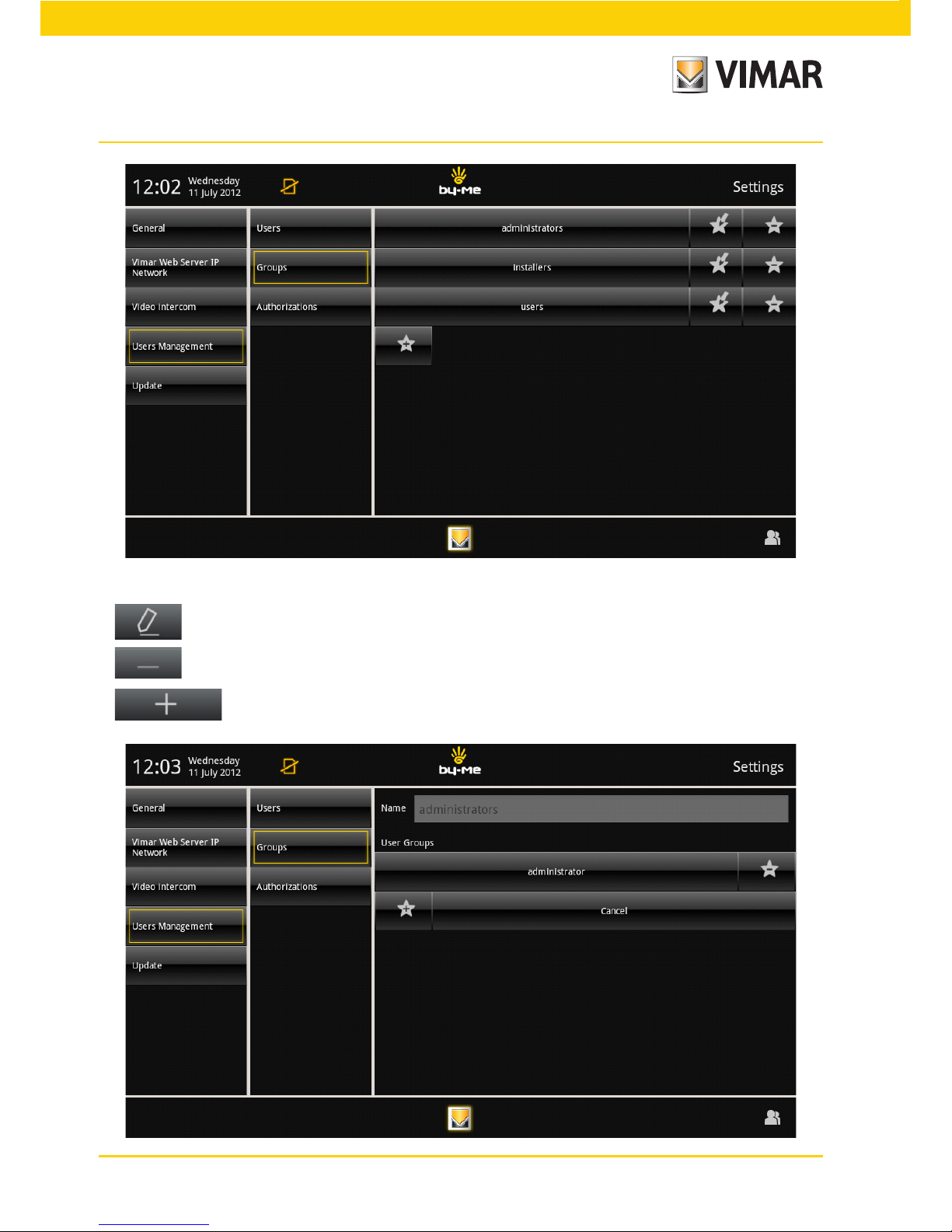
62
Touching:
- changes the settings for already configured groups;
- deletes the selected group;
- adds a new group.
User Management
Page 65

63
Touching the icon shows the screen that enables assigning users with the menus and applica-
tions they can access.
Touching the icon for the user and the desired application enables this user to utilize the
selected function.
User Management
Page 66

64
User Management
Page 67
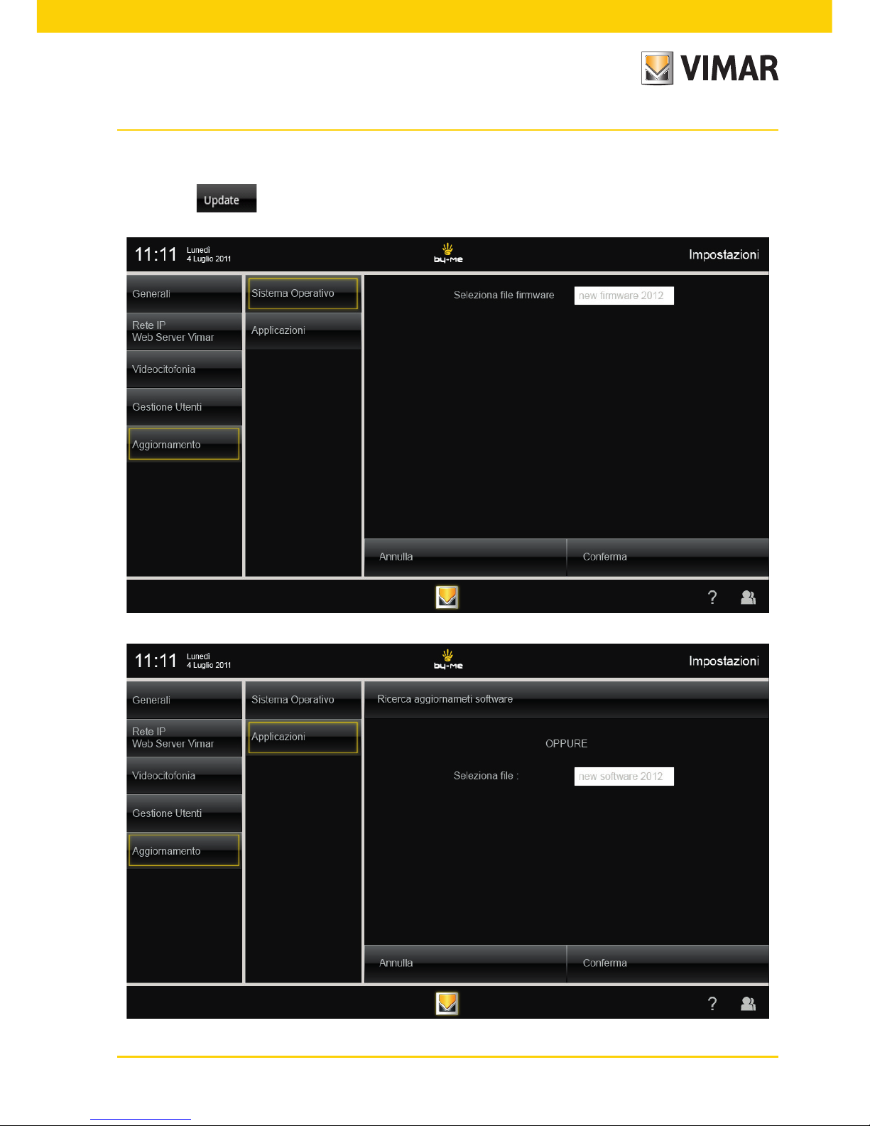
65
3.5 UPDATE.
Touching the icon displays the options that enable updating the multimedia video touch screen.
Update
Page 68
66
Update - Installation rules - Regulatory compliance
Touching the or icon displays the screens that enable downloading the
firmware of the operating system and of the applications used by the multimedia video touch screen.
After selecting the firmware to download shown in the pop-up window, touch to confirm the
update.
Page 69

67
Installing applications from Market Vimar Group
3.6 PROCEDURE FOR INSTALLING APPLICATIONS FROM MARKET VIMAR GROUP
The applications available in the "Market Vimar Group" are not pre-installed in the video touch screen multime-
dia and are dedicated to special integration with other devices (e.g., Elvox DVR) that need to be configured by
specialized personnel.
When necessary, the installer must therefore perform the processes of activation, download and installation of the
single application so that it can be used by the end user.
The following procedure describes how to carry out these operations by taking the Secuviewer application as
an example of reference to control the Elvox (Vimar Group) DVR and Elvox (Vimar Group) PTZ-type cameras.
• Starting from the main menu (with no “Secuviewer” icon) tap the icon and log in as Installer.
In the left column, as the last option, you will see the icon.
N.B. If the icon does not appear when you first log in, simply search for updates by tapping
.
• Tapping the icon displays a second column with the categories of available applications (in this
case DVR), while the area on the right will list the various applications that can be activated for the selected
category (in this case Secuviewer).
Page 70
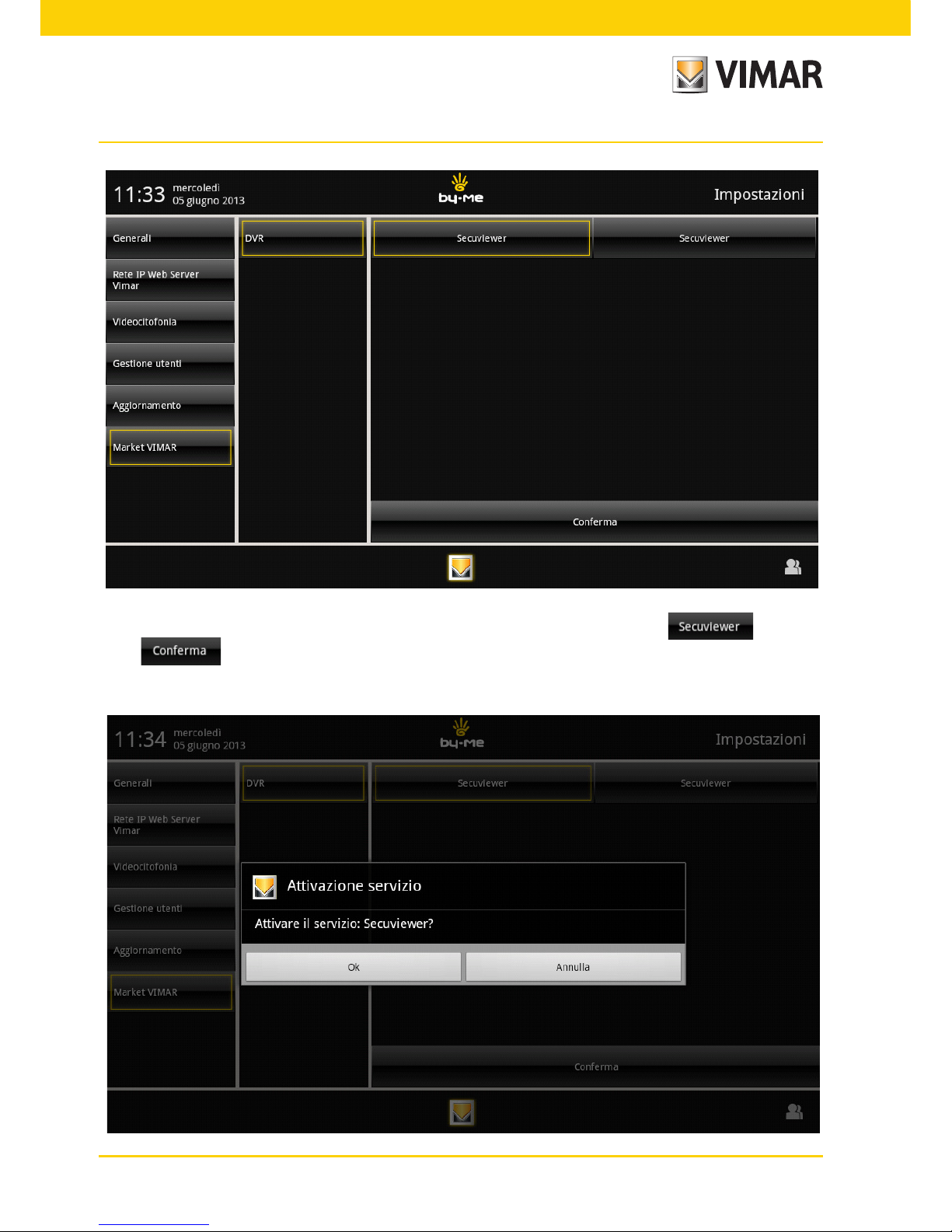
68
Installing applications from Market Vimar Group
• Tapping the icon with the name of the application chosen for activation (in this case ) and then
the icon displays a pop-up with which you can proceed with your request for activation or cancel
the operation.
Page 71
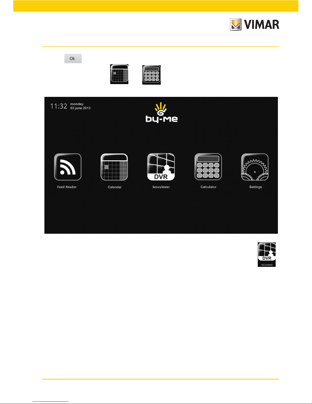
69
• Tapping will enable the new icon (in this case DVR with the title of Secuviewer) which will be displayed
on the main menu between the and icons.
• It is now necessary to download the application by tapping once on the new added icon (in this case ).
• Once the download is complete, run the installation by tapping the icon again. After a few seconds a screen
will appear for installing the application (in this case Secuviewer).
Continue with the operation leaving all the provided options selected and tap Install. On completion Application
Installed will be displayed.
• Tap the End icon to complete installation.
The new application is installed and ready for use.
Please note: the procedure and operations described above apply only to ONLINE devices (i.e., connected
to an ADSL Internet connection).
Installing applications from Market Vimar Group
Page 72
70
4. INSTALLATION RULES.
Installation should be carried out in compliance with the current regulations regarding the installation of electrical
systems in the country where the products are installed.
CAUTION: To prevent injury, the appliance must be secured to the wall as described in the installation instructions.
Above the power supply there must be a bipolar circuit breaker that is easily accessible with a contact gap of at
least 3 mm.
5. REGULATORY COMPLIANCE.
LV directive
EMC directive
Standards EN 60950-1, EN 61000-6-1, EN 61000-6-3.
Installation rules - Regulatory compliance
Page 73

71
Page 74

21553 installatore EN 03 1307
VIMAR - Marostica - Italy
Viale Vicenza, 14
36063 Marostica VI Italy
Tel. +39 0424 488 600
Fax +39 0424 488 709
http://www.vimar.com
 Loading...