

Page 1

Instructions manual
Timer-Thermostat 02910
Installer Manual
Page 2

Page 3

1
Table of Contents
1. Timer-Thermostat 02910 ………………………………………………………………………………………… 3
2. Field of application ……………………………………………………………………………………………… 3
3. Installation ………………………………………………………………………………………………………… 3
4. Connections ………………………………………………………………………………………………………… 3
4.1 Relay connection ……………………………………………………………………………………………… 3
4.2 Multi-function input …………………………………………………………………………………………… 4
4.3 Energy Probe 02960 …………………………………………………………………………………………… 4
4.3.1 Measurement of 2 or 3 phases………………………………………………………………………………… 5
4.3.2 Saving the consumption data log ……………………………………………………………………………… 5
5. Inserting new / replacement batteries ………………………………………………………………………… 9
6. Display …………………………………………………………………………………………………………… 10
6.1 Functions of the buttons …………………………………………………………………………………… 11
6.2 Symbols ……………………………………………………………………………………………………… 12
6.3 Locking the interface via PIN ……………………………………………………………………………… 13
6.4 Alternative views …………………………………………………………………………………………… 13
6.4.1 Clock and daily program …………………………………………………………………………………… 13
6.4.2 Ecometer ……………………………………………………………………………………………………… 14
6.4.3 Consulting the energy probe (if enabled) …………………………………………………………………… 15
7. Operating mode ………………………………………………………………………………………………… 18
7.1 Switched off (OFF) ………………………………………………………………………………………… 18
7.2 Manual………………………………………………………………………………………………………… 19
7.3 Auto …………………………………………………………………………………………………………… 20
7.4 Timed manual………………………………………………………………………………………………… 21
7.5 Away ………………………………………………………………………………………………………… 22
7.6 Antifreeze …………………………………………………………………………………………………… 23
7.7 Remote reduction …………………………………………………………………………………………… 23
7.8 Remote auto ………………………………………………………………………………………………… 24
8. Settings menu …………………………………………………………………………………………………… 25
8.1 Operating mode setting …………………………………………………………………………………… 26
8.2 Setting the time and day of the week ……………………………………………………………………… 26
8.3 Heating/air-conditioning setting …………………………………………………………………………… 26
8.4 Unit of measurement setting ……………………………………………………………………………… 26
8.5 Daily program setting ……………………………………………………………………………………… 26
8.5.1 Selecting the day of the week ………………………………………………………………………………… 27
8.5.2 Temperature selection ………………………………………………………………………………………… 27
8.6 Temperature setting ………………………………………………………………………………………… 28
8.6.1 Away temperature ……………………………………………………………………………………………… 29
8.6.2 Economy temperature ………………………………………………………………………………………… 29
8.6.3 Comfort temperature …………………………………………………………………………………………… 29
8.6.4 Hysteresis of the device ………………………………………………………………………………………… 29
8.6.5 Thermal delta in nighttime reduction mode …………………………………………………………………… 30
8.6.6 Antifreeze temperature ………………………………………………………………………………………… 30
8.7 Calibration setting …………………………………………………………………………………………… 30
8.8 Multi-function input setting ………………………………………………………………………………… 30
8.9 OnOff/PID temperature control algorithm setting ………………………………………………………… 31
8.10 Energy probe setting ……………………………………………………………………………………… 32
8.10.1 Configuring a phase to be measured ……………………………………………………………………… 32
8.10.2 Configuring the “power threshold” alarm …………………………………………………………………… 32
8.11 Buzzer (beep) setting ……………………………………………………………………………………… 32
Page 4

2
8.12 Info about the device ……………………………………………………………………………………… 33
8.13 Lock/unlock PIN setting …………………………………………………………………………………… 33
9. Parameters table ……………………………………………………………………………………………… 34
10. Alarms …………………………………………………………………………………………………………… 35
11. Cleaning the device …………………………………………………………………………………………… 35
12. Installation rules ……………………………………………………………………………………………… 35
13. Regulatory compliance ……………………………………………………………………………………… 35
Page 5
3
1. Timer-Thermostat 02910
Wall-mounting, battery-powered timer-thermostat with interface with capacitive keys and equipped with
user-friendly functions to facilitate energy saving.
Designed to control heating and air-conditioning via C, NC, NO relay output.
Equipped with multi-function input for remote control (reduction, activation, summer/winter switching).
Can be connected, via circuit board 02915, to the energy probe 02960 (not supplied) for viewing consumption/
generation of electricity and corresponding historical data.
If the device is used in combination with the energy probe 02960 a built-in buzzer is available.
2. Field of application
The appliance is designed to control room temperature by acting on the control circuit of the burner or circulation pump (heating) or on the control circuit of the air conditioner
(air conditioning), ensuring an ideal temperature.
The graphical user interface, thanks to special views, facilitates system management helping the user to operate while maintaining a state of energy saving.
Consultation of the energy consumption (or generation) carried out by connecting to the energy probe 02960,
lets you monitor up to 3 separate phases (with common neutral), for a maximum of 10kW per phase. The
device will not activate/deactivate loads, depending on the powers read (only monitoring with audible alarm,
if any).
3. Installation
The appliance must be installed on a wall at a height of 1.5 m off the floor in a suitable position for correctly
detecting the ambient temperature. It must not be installed in niches, behind doors and curtains or in areas
affected by sources of heat or atmospheric factors.
The timer-thermostat is a wall-mounting device that can be installed directly on a wall or on 2 and 3 module
back boxes.
It should be used in dry, dust-free places at a temperature between 0°C and +40°C.
4. Connections
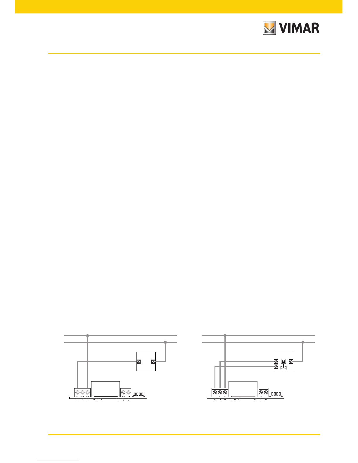
4.1 Relay connection
L
N
U1
NO NC C
L
N
U1
APRE
CHIUDE
NO NC C
Circulation pumps, burners, solenoid valves Motorized valves
Page 6
4
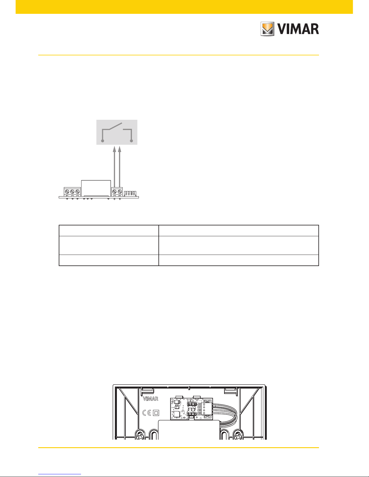
4.2 Multi-function input
Depending on how it is configured, the multi-function input can be used to activate various functions of
the timer-thermostat (see par. 7.8 and 7.9).
It is on when the two terminals of the figure are closed by a dry contact; vice versa if they are open, the
input is off. The contact must be SELV and free of potential.
The typical wiring diagram is the following:
NO NC C
FUNCTIONS
- Remote nighttime reduction
- Remote ON
- Summer/Winter switching
Fig. 1: Connecting the multi-function input
Activation type dry contact
Type of conductor
1 single wire or 1 multi-wire cable conductor
MAX. 1.5 mm
2
Length of the conductor max. 100 m between the 2 terminals
4.3 Energy Probe 02960
For the timer-thermostat to be able to communicate with the energy probe 02960 it is necessary to use
the circuit board 02915 that is to be installed on the wall base.
Connect the circuit board 02915 and energy probe 02960 using a UTP CAT5E cable or better; the RJ9
phone connector for connecting to the probe must be wired in such a way as to have one pair of wires
between terminals 1 and 4 (outer pair) and the other between pins 2 and 3 (inner pair).
Take care to keep consistent connections at the terminals.
For example:
• 5V orange
• A blue
• B white-blue
• GND white-orange
A
B
–
5 V
1
A
B
GND
23
MADE IN ITALY
02910
+
–T40
Page 7
5
4.3.1 Measurement of 2 or 3 phases
The energy probe 02960 comes with a single current probe (for measuring the consumption/
production of a single phase); to measure more than one phase it is essential to have more
current probes 01457 (one for each additional phase to be measured). Once connected, you
must enable the new channel (the new phase to be measured) using the menu described
in par. 7.12.1.
4.3.2 Saving the consumption data log
In order for the energy probe to save the consumption data log properly, the latter must receive
the time setting from the timer-thermostat; then the clock must be correctly set (see par. 7.3). The
energy probe can save the consumption data log for a very long time (up to 3 years), provided
that its power supply is not interrupted for more than 7 consecutive days (at each start the time
must be reset by the timer-thermostat).
If the probe should remain switched off for over a week, the entire switch-off period would be
reduced in any case to a week (at most) with a loss of consistency in the log view; in this case,
to avoid inconsistent readings, you may want to reset its data log.
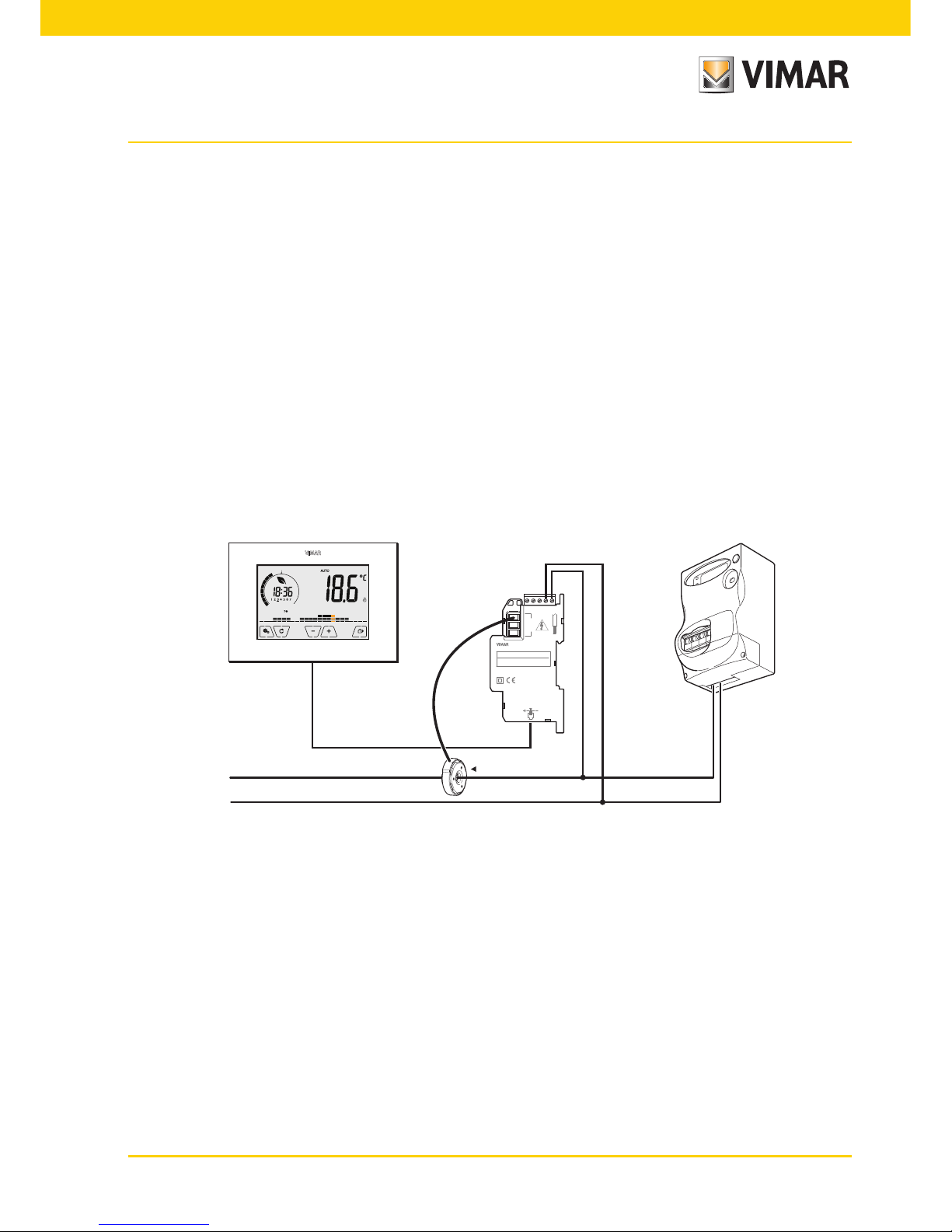
Here are some typical examples of installation of the energy probe:
L
1
N
L
N
CTRY OF MFG
PAT. PEND
PA3832NL
DATE CODE
I
RS-485
L N N
3
S
6mm
3
S
2
S
1
L
2
L2L
1
L N
A B
120-230V 5mA
50/60Hz
50/60Hz
50/60Hz
230/400V
127/220V
1
L N
3
L
1
SENSOR
ENERGY METER
02960
MADE IN ITALY
Fig. 2: Basic configuration, for measuring household absorption
Page 8
6
L N N
3
S
6mm
3
S
2
S
1
L
2
L2L
1
L N
A B
120-230V 5mA
50/60Hz
50/60Hz
50/60Hz
230/400V
127/220V
1
L N
3
L
1
SENSOR
ENERGY METER
02960
MADE IN ITALY
CTRY OF MFG
PAT. PEND
PA3832NL
DATE CODE
L
1
L
2
N
L
L
L
N
I
CTRY OF MFG
PAT. PEND
PA3832NL
DATE CODE
I
RS-485
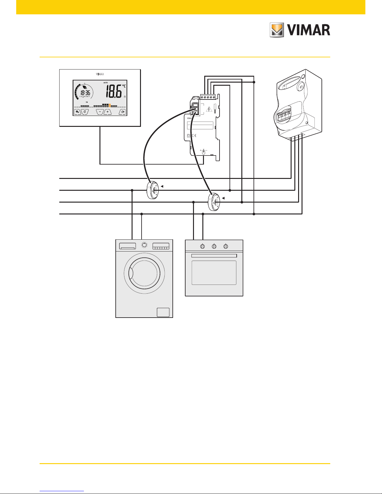
Fig. 3: Measurement of the total consumption of a system, also with (single-phase) loads distrib-
uted over multiple phases.
Page 9
7
L N N
3
S
6mm
3
S
2
S
1
L
2
L2L
1
L N
A B
120-230V 5mA
50/60Hz
50/60Hz
50/60Hz
230/400V
127/220V
1
L N
3
L
1
SENSOR
ENERGY METER
02960
MADE IN ITALY
CTRY OF MFG
PAT. PEND
PA3832NL
DATE CODE
L
N
I
RS-485
L
1
N
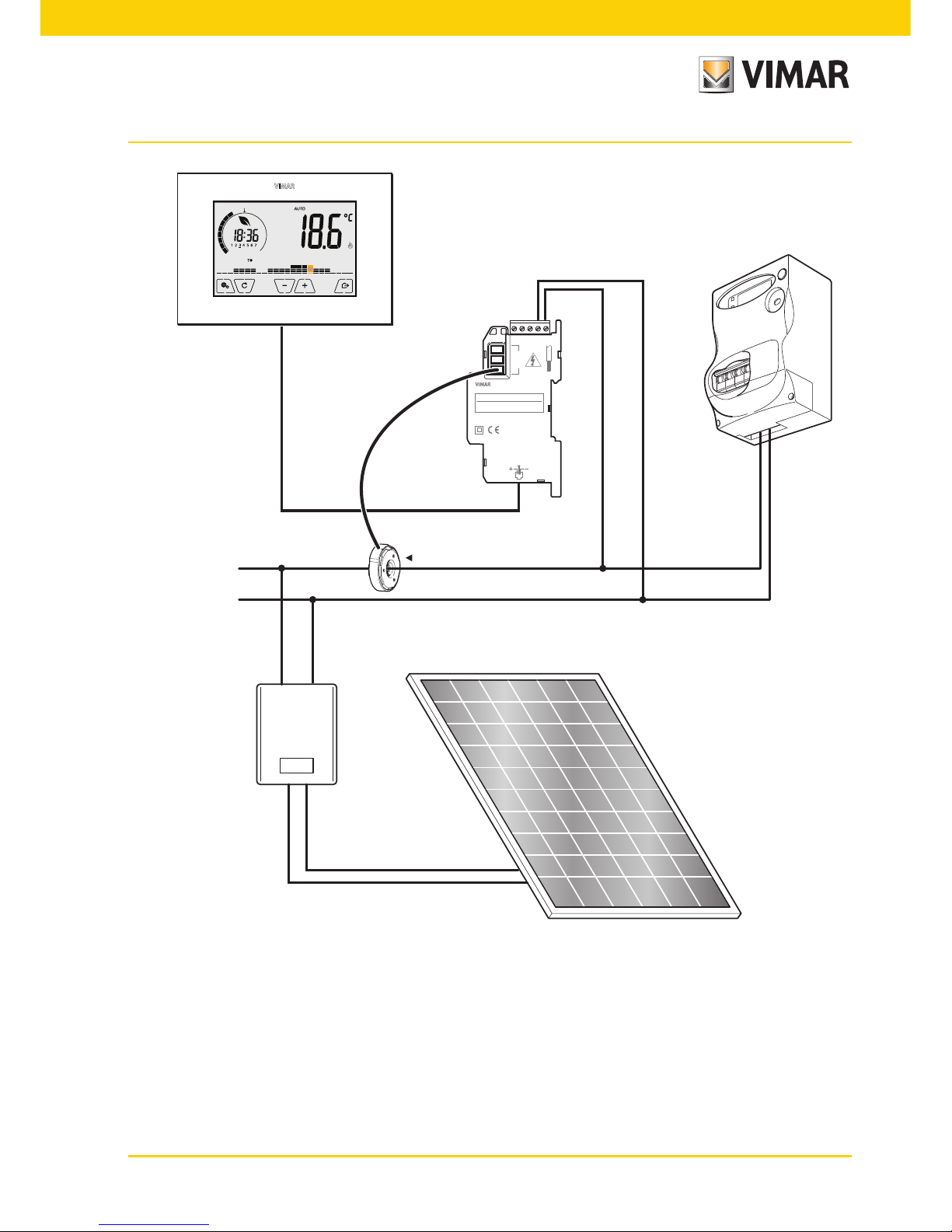
Fig. 4: Measurement of net consumption or generation with a photovoltaic system installed. In
cases of generation via a photovoltaic panel (fed into the national grid), the probe will
record a NEGATIVE value, which corresponds to energy generation (the opposite of
consumption).
INVERTER
Page 10

8
L N N
3
S
6mm
3
S
2
S
1
L
2
L2L
1
L N
A B
120-230V 5mA
50/60Hz
50/60Hz
50/60Hz
230/400V
127/220V
1
L N
3
L
1
SENSOR
ENERGY METER
02960
MADE IN ITALY
CTRY OF MFG
PAT. PEND
PA3832NL
DATE CODE
L2L
1
N
L
N
I
CTRY OF MFG
PAT. PEND
PA3832NL
DATE CODE
I
RS-485
Fig. 5: Measurement of differentiable consumption and generation with a photovoltaic system
installed. Observe the direction of installation of the current probe S2: in cases of
generation via a photovoltaic panel, the probe will record a NEGATIVE value, that
corresponds to energy generation (as opposed to consumption).
INVERTER
Page 11

9
5. Inserting new / replacement batteries
When replacing batteries, remove the front panel by raising it with a screwdriver. Replace the batteries with
Alkaline 1.5V "AA" batteries.
CAUTION!
In case of replacement, dispose of batteries in the specific
differentiated collection bins
Fig. 6: Changing batteries
The battery charge status is shown as follows:
• no icon battery charged
• flashing icon battery almost flat (replace it)
• fixed on icon battery flat (the device will go OFF and it is no longer possible to switch to operation).
Page 12
10
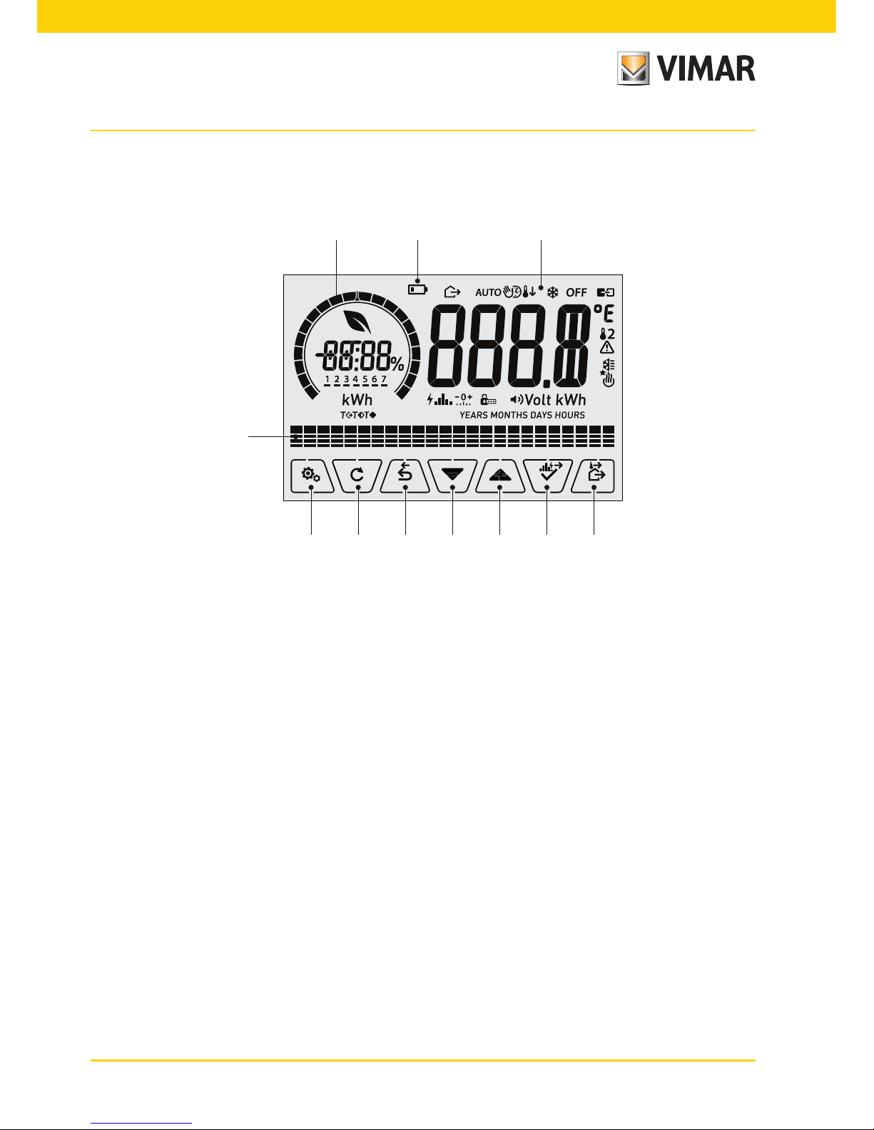
6. Display
The touchscreen display allows you to control the system using the following buttons and icons:
M
L
I H G F E D
A B C
Fig. 7: Graphical interface and buttons
A: Ring indicating consumption level and energy savings indicator
B: Battery charge status
C: Operating mode
D: Away
E: Confirm or energy log navigation
F-G: Menu navigation and setting parameters
H: Back
I: Alternative viewing
L: Settings menu
M: AUTO programme temperature trends and consumption log
Page 13

11
6.1 Functions of the buttons
: increases the numerical values. When it "disappears" from the display it means that the value
cannot be increased any more.
: decreases the numerical values. When it "disappears" from the display it means that the value
cannot be decreased any more.
: during navigation, it scrolls the next item through the available menus. If it "disappears" then
you have arrived at the last of the items that can be scrolled.
: during navigation, it scrolls the previous item through the available menus. If it "disappears"
then you have arrived at the last of the elements that can be scrolled.
: confirms the selected option (activates the submenu if there is one or displays the next
parameter/digit).
After each confirmation, the display shows the icon for approximately 1 s. In addition, if
the timer-thermostat is connected to the probe 02960 via the circuit board 02915, it will also
be possible to enable its acoustic signal.
: back (or cancel) exits the current screen/menu and returns to the previous one without
saving any changes. In menus with changes to multiple digits it lets you go back to change
the previous digit.
N.B. The field/value being edited is highlighted by the field/value itself flashing.
IMPORTANT: In order to avoid any accidental modifications, first press and hold down the required
icon displayed to enable the function.
Page 14
12
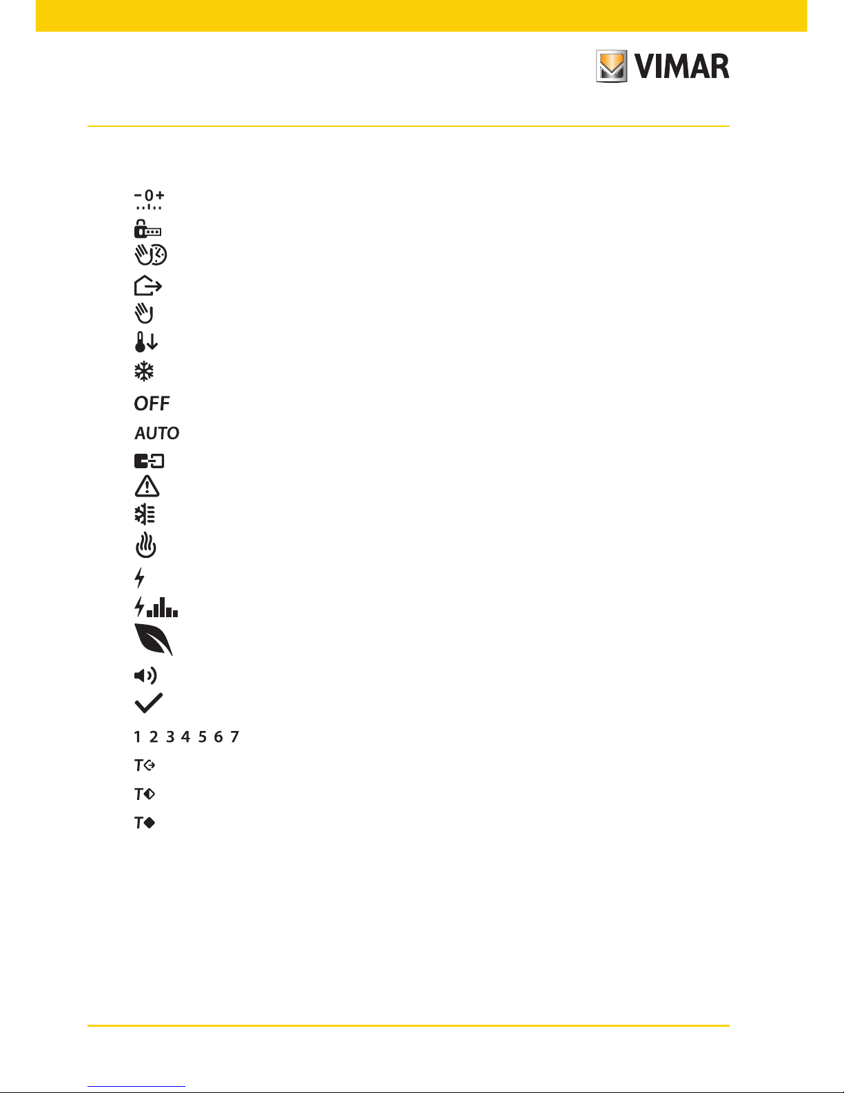
6.2 Symbols
Depending on the different operating modes, the display shows the following icons:
: Calibration
: Entering the PIN
: Timed manual operation
: Away
: Manual
: Nighttime reduction
: Antifreeze
: Switched off (OFF)
: Automatic operation
: Multi-function input ON
: Alarm
: Air conditioning
: Heating
: Power/Energy
: Energy consumption log
: Eco (saving)
: Buzzer (beep)
: Confirm
: Day of the week indicator
: Away temperature
: Economy temperature
: Comfort temperature
Page 15

13
6.3 Locking the interface via PIN
The timer-thermostat lets you set a password which inhibits any change to the operating mode (eg
switching from Manual to OFF), limits setting the temperature values and, more generally, blocks access
to the configuration menu.
This feature is useful to prevent the thermostat being used by unauthorized persons: the device prompts
you to enter the PIN, indicating a shutdown with the icon.
Fig. 8: Locking with PIN
6.4 Alternative views
During normal operation, i.e. when you are not navigating the menus, you can select the information to
display on the left-hand side of the display.
If the right side always displays the measured temperature together with other data (which will be
explained below), tapping in succession the button on the left-hand side and in the program area
will display the two following options:
6.4.1 Clock, daily program and Ecometer
Fig. 9: Typical view of the time and daily program
This view is the default and gives an indication of the daily temperature control program along with
the data on the current moment.
The program area, represented by histograms, is divided into 24 sectors each of which repre-
sents the corresponding hour of the 24 hours in a day.
Energy saving indicator
Clock
Day of the week indicator
Set temperature indicator
Daily program
Page 16

14
Each sector can be composed of 1, 2 or 3 dashes:
equivalent to “T away” ( )
equivalent to “T economy” ( )
equivalent to “T comfort” ( )
The clock shows the current time.
The indicator of the day of the week highlights the current day with a dash under the number
associated with it (eg, 4 = Thursday).
The set temperature indicator highlights the current temperature being regulated thus replicat-
ing the information represented by the “dashes”:
= T away
= T economy
= T comfort
The energy saving indicator indicates whether, compared to a conventional average consump-
tion, the set temperature setpoint enables you to achieve "savings" in consumption.
If the operating mode is not set on AUTO, the program area will not be active.
Fig. 10: Typical view of ecometer mode
The set of icons called "ECOMETER" provides a general indication of the expected consumption
facilitating energy saving.
The consumption forecast is given by a comparison between the currently set temperature value
and a conventional average consumption defined in the device.
• The ring of the level of consumption indicates the level of expected consumption; if the level is
less than half then savings are expected with respect to the conventional average consumption,
whereas if the level exceeds half then the expected consumption will be greater than average.
• The energy saving indicator indicates whether, compared to the conventional average con-
sumption, the set temperature setpoint enables you to achieve "savings" in consumption.
Ring for the level of consumption
Indicator for
energy saving
Page 17

15
6.4.3 Consulting the energy probe (if enabled)
Fig. 11: Typical screen for consulting the energy probe
This option is used to consult data on the instantaneous power and energy consumed/generated
by the system and measured instantly by the energy probe.
CAUTION: Proper operation and proper consultation require:
• The energy probe 02960 to be powered and functioning
• The energy probe 02960 is properly interconnected with the circuit board 02915
• The clock of the timer-thermostat to be set correctly
If these conditions are met, the indicator LED of the energy probe 02960 will flash "slowly"
(1 flash every 2 seconds approximately).
The measured power is the value measured by the energy probe 02960; the value shown is the
sum of the (active) powers of all the active channels of the probe (eg, all 3 channels could be
active, or only channel 1 or channels 1 and 3, etc.).
The unit of measurement (W or kW) is displayed under the measured value.
• If the sum of the powers turns out to be consumed (i.e. absorbed by the energy supplier), the
value is positive and the generation/consumption indicator is off.
• If the sum of the powers turns out to be generated (for example, the photovoltaic system is
supplying power to the electricity grid), the value is negative and the generation/consumption
indicator is on.
When consulting the power/energy data, the "consumption log" view provides a rough estimate
of the consumption recorded in the last period. In particular, each horizontal group of dashes represents the year/month/day/hour depending on whether the word displayed is YEARS/MONTHS/
DAYS/HOURS respectively.
The current year/month/day/hour is highlighted by the group of flashing dashes while the
previous and the next are represented by groups of dashes shown respectively to the left and
right of the flashing group.
Comparison ring with
the average power
Indicator for
production/consumption
Measured power
Unit of measurement
Button for consulting energy log
Page 18

16
The information provided is represented as follows:
indicates consumption less than half the average consumption
indicates consumption in line with the average
indicates consumption 1.5 times higher than the average
The circular ring (only when consulting the instantaneous power) represents the current level of
consumption compared to the maximum level recorded in the last 24 h (ring complete with all the
dashes = maximum consumption); the number of dashes can therefore vary even if the power is
the same since what is displayed depends on the consumption log.
Pressing and holding the central area (see fig.7), instead of the instantaneous power, displays the
energy consumed (or generated) during the current day; in this case the circular ring represents
the level of consumption of the current day compared to the last 30 days. If the dashes reach
halfway around the ring it means that the consumption in the last 24 hours is in line with that of
the last 30 days; vice versa, if the dashes exceed or are less than half of the ring it means that the
current consumption is respectively higher or lower than the average of the last 30 days.
6.4.3.1 Consulting the energy log
Touching displays the historical data on energy consumption measured and saved
by the energy probe 02960.
Fig. 12: Typical view of historical energy data consultation
Via and and confirming with you set the range of historical consumption that you want to see:
Page 19

17
• (historical data reset): this option lets you delete ALL the historical data saved
by the energy probe; since this operation cannot be undone, an additional confirmation
screen is displayed (YES to delete and NO not to delete).
• (hourly consumption): enables you to scroll one by one through the hours prior to
the current one; the indices range from “0h” (current hourly consumption) to “-23h”
(hourly consumption of 23 hours ago).
• (daily consumption): enables you to scroll one by one through the days prior to the
current one; the indices range from “-0D” (current daily consumption) to “-30D” (daily
consumption of 30 days ago).
• (monthly consumption): enables you to scroll one by one through the months prior to
the current one; the indices range from “-1M” (monthly consumption of the last month)
to “-11M” (monthly consumption of 11 months ago).
N.B.: Monthly consumption (or generation) is considered to be the consumption (or
generation) recorded in a fixed period of 30 days. The month “-1M” therefore represents
the consumption recorded in the period from 30 days ago until yesterday. The month
“-2M” represents the consumption recorded in the period from 60 days ago until 31
days ago, etc.
• (yearly consumption): enables you to scroll one by one through the years prior to the
current one; the indices range from “-1Y” (yearly consumption of the last year) to “-3Y”
(yearly consumption of 3 years ago).
N.B.: Yearly consumption (or generation) is considered to be the consumption (or
generation) recorded in a fixed period of 365 days. The year “-1Y” therefore represents
the consumption recorded in the period from 365 days ago until yesterday. The year
“-2Y” represents the consumption recorded in the period from 730 days ago until 366
days ago, etc.
Confirming the selection will then display the energy consumed or generated in Wh or
kWh. Obviously, if the energy probe was installed at a time when there were not yet any
data for the period of consultation, the historical energy data will be 0.
For example, if the probe was installed 20 days ago and we are consulting the term "-3
months" then the consumption is obviously 0 Wh.
Page 20

18
7. Operating mode
The timer-thermostat 02910 is able to regulate the temperature according to the following operating modes:
• Switched off (OFF): switches the system off
• Manual (ON): lets you set the environment temperature set-point manually
• AUTO: lets you set a control program that compares the room temperature with the value set for each
quarter of an hour of the current day; the user defines three levels of temperature distributed over 24 hours
which can then be varied for each day of the week.
• Timed manual: starting from AUTO mode, this lets you activate MANUAL operation of the timer-thermostat
for any period of time at the end of which the device will return to AUTO mode.
• Away: lets you set the set-point in order to achieve significant energy savings during periods when the user
is away
• Antifreeze: used to set a minimum temperature level to avoid damage to pipework or prevent the temper-
ature from falling below a safety level.
In addition, if the multi-function input of the timer-thermostat has been suitably configured, you can remotely
activate the following modes:
• Remote reduction: lets you vary the set points of MANUAL adjustment to obtain energy savings.
• Remote activation: lets you activate the system remotely, setting AUTO operation.
• Summer/Winter switching: the multi-function input automatically switches the timer-thermostat onto
air-conditioning mode (when on) or heating mode (when off).
The operating mode is selected via the SETTINGS menu or with the shortcut keys.
7.1 Switched off (OFF)
With this mode on, the timer-thermostat is turned off and you cannot make any adjustments; in this case,
the icon is displayed above the temperature indicator.
In this mode you cannot perform any operations other than activating the menus or changing the view
mode.
Fig. 13: Typical screen for OFF mode
For heating-only systems this mode is typically used in the summer.
Page 21

19
7.2 Manual
In this mode the device operates as a simple thermostat and regulates the ambient temperature, taking
it to the value set by the user.
When MANUAL mode is active, the icon is displayed above the temperature indicator.
Fig. 14: Typical screen for Manual mode
The set point can always be changed via or .
Fig. 15: Manual set point setting
The selection is confirmed by touching .
The and icons in the lower right corner indicate whether the system is operating in heating or
air-conditioning mode respectively (icon illuminated = system on).
Page 22

20
7.3 Auto
This is the typical mode of operation of the timer-thermostat.
The device automatically changes the ambient temperature according to the time of day and the day of
the week, it minimizes user intervention thereby optimizing comfort and energy savings; three different
temperatures can be set to cover the needs of normal use, user away or nighttime reduction in the
environment.
For setting the automatic program, see par. 8.5.
When AUTO mode is active, the icon is displayed above the temperature indicator.
Fig. 16: Typical screen for Auto mode
By touching and you can temporarily change the ambient temperature, setting it to a different value to the one associated with the current time slot.
Confirming with it then goes into TIMED MANUAL mode.
The and icons in the lower right corner indicate whether the system is operating in heating or
air-conditioning mode respectively (icon illuminated = system on).
Page 23

21
7.4 Timed manual
This mode allows you to exit the AUTO program (you enter MANUAL mode) for a certain time after which
the timer-thermostat will return to AUTO mode.
For example: take the ambient temperature to 25°C for 2 hours and then resume the Auto program.
Activation is carried out starting from AUTO mode and is recognizable by the icon displayed above
the temperature indicator.
Fig. 17: Input screen in Timed Manual mode
Using and you set the temperature and confirm with .
The next screen, again using and , lets you set the time for which the temperature you have
just set is maintained.
Fig. 18: Regulating the number of hours of Timed Manual mode
Finally confirm with .
At the end of the set time the timer-thermostat goes back into AUTO mode, the icon switches off
and reappears.
Page 24

22
7.5 Away
This mode is useful to achieve energy savings quickly and effectively whenever the user leaves the regulated room.
In "Away" mode the system makes the adjustment according to the "away temperature" setpoint .
The Away mode can only be activated by touching .
The display will show the "away temperature" setpoint for approximately 2 seconds:
Fig. 19: Input in away mode showing the away temperature
Mode activation is identified by the icon:
Fig. 20: Away Mode
To exit and return to the initial mode touch the button again:
Page 25

23
7.6 Antifreeze
This mode, which can only be activated when the system is operating in heating mode, lets you set a
minimum temperature value ( setpoint) to avoid damage to the pipework or to keep it from falling below
a certain safety level when you are away for lengthy periods in the winter.
The "antifreeze" mode is activated directly from the Settings menu.
Once activated, antifreeze mode is identified by the icon above the temperature indicator.
Fig. 21: Antifreeze mode
7.7 Remote reduction
Remote reduction is a useful way to "centralize" energy saving if there are multiple 02910 thermostats in
different rooms of the same house.
Example: Before going to bed, using a simple switch, all the thermostats in the house are set onto "reduction" at the same time.
This mode comes into operation when the multi-function input is activated only if this has been
suitably configured; the multifunction input is activated solely when the timer-thermostat, before
the activation, is in Manual mode (otherwise the multi-function input is ignored).
In "Remote reduction" mode, the device regulates the temperature to a value equal to Tcomfort ; in this condition, the display and the relevant buttons must not be used (this is because the device is
controlled by remote).
The "Remote reduction" mode is identified by the and icons located simultaneously above the
temperature indicator.
Page 26

24
Fig. 22: Input in Remote reduction mode
7.8 Remote auto
This mode is typically used in applications where you want to remotely enable or disable temperature
control of a room and limit the functions that can be performed by the user.
This mode comes into operation when the multi-function input is activated (see par. 4.2) only if it
has been suitably configured.
In this condition, the display and the relevant buttons must not be used.
The "Remote auto" mode is identified by the and icons located simultaneously above the
temperature indicator.
Fig. 23: Typical screen in Remote auto mode
Page 27

25
8. Settings menu
From the settings menu you can configure all the features of the timer-thermostat.
On the main screen tap the icon.
From the main menu, using and will display the following (flashing) symbols in succession, which
provide access to the corresponding submenus:
1. operating mode setting
2. setting the time and day of the week
3. air-conditioning/heating setting
4. unit of measurement setting
5. daily program setting
6. temperature setpoint setting
7. calibration setting
8. and multi-function input setting
9. OnOff/PID temperature control algorithm setting
10. energy probe setting
11. buzzer (beep) setting
12. device info
13. lock/unlock PIN setting
Touching opens the submenu and then the flashing highlights the parameters of the submenu.
Page 28
26
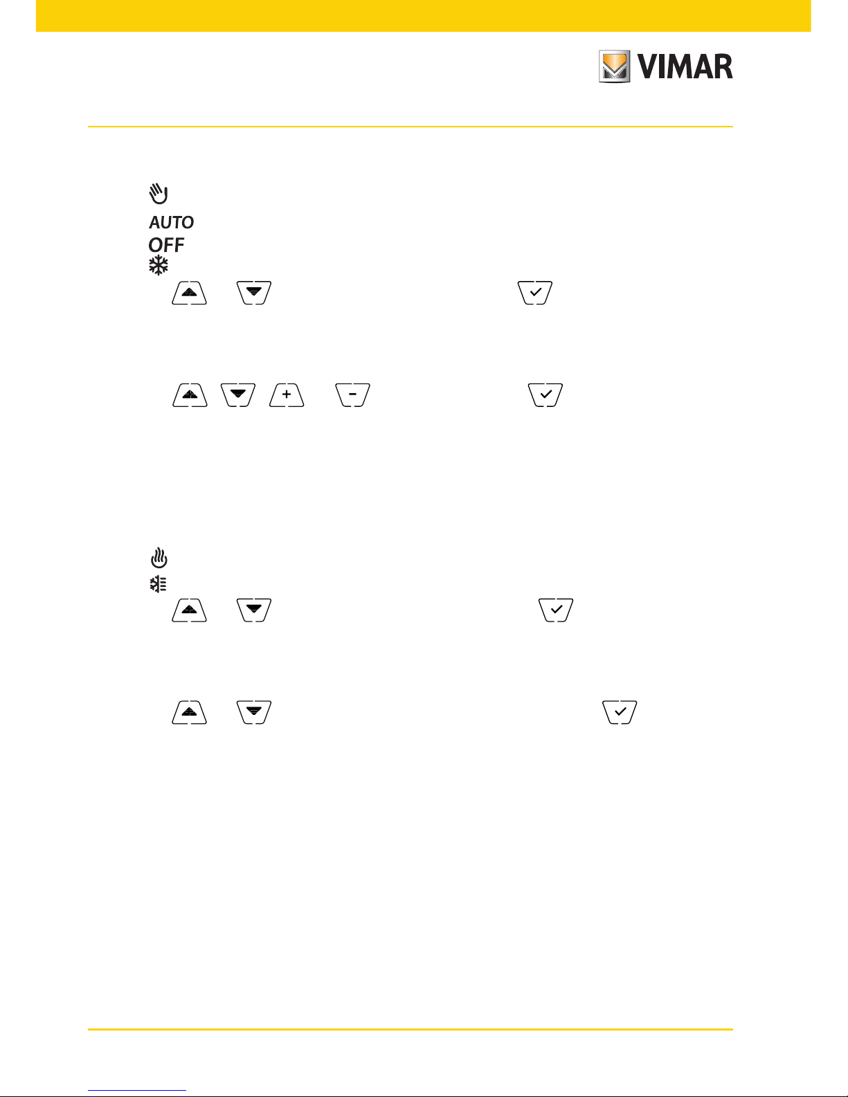
8.1 Operating mode setting
This menu is used to select the operating mode of the device:
• Manual
• Automatic
• Off
• Antifreeze (only if the thermostat is set on "heating")
Using and select the desired mode and confirm with .
8.2 Setting the time and day of the week
This menu lets you set the time and day of the week.
Using , , and set the hour, confirm with and similarly set the minutes
and then the day of the week.
The days of the week are represented by numbers from 1 to 7 and indicate the days from Monday to
Sunday.
8.3 Heating/air-conditioning setting
This menu lets you set the operation of the device depending on the season (winter/summer):
• heating
• air-conditioning
Using and select the desired operation and confirm with .
8.4 Unit of measurement setting
This menu lets you set the unit of measurement used for the temperature (°C or °F)
Using and select the desired unit of measurement and confirm with .
8.5 Daily program setting
This menu lets you set or modify the time and daily program for the ambient temperature.
The program lets you associate each quarter hour of the day (and in a different way, for each of the 7 days)
with one of the 3 temperatures "T comfort", "T away" and "T economy".
For example: During the night, set "T economy", for the morning and evening set "T comfort" and in the
middle of the day set "T away" (when no one is in the environment and to obtain savings due to a lower
consumption).
Page 29

27
8.5.1 Selecting the day of the week
As soon as you enter the menu, the display shows a flashing dash for the day to which the current
programming refers (for example: 1234567 = Tuesday).
Using and select the day of the week to program and confirm with .
8.5.2 Temperature selection
After confirming the day to program, the display shows the screen for setting the temperatures
associated with the different times of the day.
Fig. 24: Setting the time and daily program
Using and
select the temperature to be associated with the current time (which is
shown on the clock on the left). This temperature, highlighted by the blinking, can be selected
from:
: away temperature (T away)
: economy temperature (T economy)
: comfort temperature (T comfort)
The "dashes" blinking indicate the time slot that you are setting (there are 24 groups of 3 dashes
and each group corresponds to one hour of the 24 in the day). The selected temperature will be
applied beginning at the time indicated on the left for all of the next quarter of an hour.
On touching , the temperature selected for the current time is assigned to the next quarter
of an hour too; in this case the temperature symbol is the same but the current time, shown by
the clock, is moved forward by 15 minutes.
Page 30

28
Using and you can move respectively between the hours of the day and move
forwards or backwards 15 minutes at a time.
During the movement, as well as the clock, also the "dashes" indicate the time of day in which
you are working. In addition, below the numbers associated with the days of the week, you will
see an icon that identifies the temperature set for that specific time.
The and buttons permit changing the set temperature.
Programming ends when the temperatures have been set for all the hours of the day and the
clock displays the time 23:45; then tap to confirm.
Finally, using and , select one of the following options shown in the numeric field of
the display:
: to copy the entire time program for the current day to the next day (useful for repli-
cating working days or holidays).
: to move on to program the next day without making a copy of the day you have
just set (useful when switching between programming working days and holidays).
: to finish programming.
Touch to confirm the selected option.
8.6 Temperature setting
This menu lets you set the temperatures and hystereses necessary for defining the temperature control
set-point used in the different operating modes.
In particular, you can have setpoints for:
1. and : Away temperature (T away) *
2. and : Economy temperature (T economy) *
3. and : Comfort temperature (T comfort) *
4. : hysteresis of the device (only if in OnOff adjustment mode)
5. and : thermal delta in remote reduction mode
6. and : “antifreeze” mode temperature (only if in “heating” mode)
* CAUTION: Depending on the mode the timer-thermostat is in (heating or air-conditioning), setting
these setpoints acts only on the value associated with the current mode highlighted by the or
icon (for example, T.comfort of heating mode).
After then changing the setpoints of the current mode in succession, change the mode (see 8.3)
and set all the setpoints corresponding to it.
Page 31

29
8.6.1 Away temperature
The menu, via and , lets you increase/decrease the value of the away temperature
and .
The away temperature is an intermediate temperature geared to obtain substantial energy savings
during periods when the user is away.
The away temperature differs depending on whether you are in the heating or air-conditioning
mode.
8.6.2 Economy temperature
The menu, via and , lets you increase/decrease the value of the economy temperature and .
The Teconomy temperature allows energy savings if applied during the nighttime (when it is pointless and costly to maintain the same setting as the daytime hours).
The economy temperature differs depending on whether you are in the heating or air-conditioning
mode.
8.6.3 Comfort temperature
The menu, via and , lets you increase/decrease the value of the comfort temperature
and .
The Tcomfort temperature can be defined as the "comfort temperature" that you want to reach
during the hours when people are present in the rooms of the dwelling.
The comfort temperature differs depending on whether you are in the heating or air-conditioning
mode.
8.6.4 Hysteresis of the device
The menu, via and , lets you set the temperature range of the heating/air-conditioning system between "ON" and "OFF".
This value can also be changed via the submenu for ON/OFF operation.
The parameter cannot be changed if the timer-thermostat is set as PID operation.
For example: Heating, with setpoint on 20.0°C, : 0.5°C 20.5 (off), 19.9 (on)
Page 32

30
8.6.5 Thermal delta in nighttime reduction mode
The menu, via and , lets you set the difference between the remote reduction temperature and Tcomfort temperature.
The remote reduction mode can only be activated via the multi-function input.
The hysteresis is a temperature increase/decrease that is applied to the Tcomfort temperature
when the multifunction input is activated). The value of the thermal delta is identical in both heating
and air conditioning with the only difference being that in the former case it determines a decrease
in the set point while in the latter case it determines an increase.
8.6.6 Antifreeze temperature
The menu, via and , lets you increase/decrease the value of the antifreeze temperature and .
Antifreeze mode is used to set a minimum temperature level to avoid damage to the pipework or
keep the room temperature from falling below a safety level.
8.7 Calibration setting
This menu lets you "calibrate" the temperature read by the timer-thermostat.
Using and , you can add or subtract (at intervals of 0.1°) a fixed amount from the temperature detected by the timer-thermostat to make it equal, for example, to that of a sample thermometer.
CAUTION: For correct calibration it is recommended to wait until the timer-thermostat has been on
for at least 1 hour in a room at constant temperature.
Tap
to confirm your choice.
8.8 Multi-function input setting
This menu is used to set the operating mode of the multi-function input.
Via and you can select the following options:
• : the state of the multi-function input is ignored by the device.
• (Remote auto): the multi-function input (when enabled) activates the timer-thermostat in “Auto”
mode. In this situation the user cannot carry out any operations on the device other than consult the
main screen; with the multi-function input disabled, the default mode is "Antifreeze" (or OFF if on air-conditioning) and the user can manage the timer-thermostat completely.
• (remote reduction): the multi-function input (when enabled) forces a reduction in temperature
(which can be set via the submenu associated with that selection) with respect to “Tcomfort”.
In this situation the user cannot carry out any operations on the device other than consult the main screen;
with the multi-function input disabled, the timer-thermostat goes back into the previously set operating
mode and the user can manage the device completely.
Page 33

31
• (summer/winter switching): the multi-function input automatically switches the timer-thermostat
onto air-conditioning mode (when on) or heating mode (when off).
This option is useful for centralized systems in which the air-conditioning or heating mode is performed
at the level of the entire building and impacts on many sub-environments.
Tap to confirm your choice.
8.9 OnOff/PID temperature control algorithm setting
This menu lets you select the way in which the ambient temperature will be controlled
Via and you can select the following options:
• (OnOff control): this is the traditional "threshold" control so that, on exceeding the set tem-
perature increased by (vice versa for air-conditioning), the heating is switched off to then be turned
back on when the room temperature drops below the set temperature.
The value can be set directly via the submenu that follows this selection.
• (P.I.D. control): this is an evolved algorithm that is able to keep the temperature in the envi-
ronment more stable, increasing comfort; this algorithm switches the system on and off appropriately so
there will be a gradual increase or decrease in the thermal (or refrigerating) power of the system itself.
To take full advantage of its performance it needs to be suitably calibrated according to the type of environment and heating system; in the light of this, the following parameters must be set via the submenus
that follow this selection:
• (breadth of adjustment range): starting from the set temperature, Tb is the temperature range
in which the heating power goes from 0% to 100%.
For example: with the temperature (for heating) set to 20.0°C and Tb=4.0°C, the thermostat activates the heating system on 100% when T.ambient is <= 16.0°C; as this temperature increases, the
system power is consequently lowered down to 0% when the ambient temperature reaches 20°C.
The value of Tb must be set consistently with the thermal capacity of the system; in general, it is
recommended to use small values of Tb for environments with a good level of thermal insulation
and vice versa.
• (system cycle time): this is the time in which a cycle of regulation is completed; the shorter this
time, the better the regulation but the temperature control system is under greater stress.
Page 34

32
8.10 Energy probe setting
When the energy probe is connected to the device, the menu is accessible and allows you to enable or
disable the measurement of each phase or configure the "power threshold" alarm.
There are the following submenus:
• If “P1” or “P2” or “P3” blink it is possible to enter the submenu for configuring phases 1, 2 and 3 of
the energy probe.
• If the and ”kW” icons blink it is possible to enter the "power threshold" alarm submenu.
8.10.1 Configuring a phase to be measured
To measure the power/voltage of phases 2 and 3 (or 1 if previously disabled) you need to enable
them via this submenu and for each one of them set the calibration value of its current probe
01457.
• With confirm the selection of “P1”,“P2”,“P3”, using and you can enable or
disable the respective phase by selecting ON or OFF and confirming with .
• After the above setting, if the channel is enabled, the display will prompt you to enter the 3-digit
number printed on the label applied to each probe 01457 (for example, 12B); using ,
and confirming with enter the 3 digits one at a time.
Note: If the channel (1 or 2 or 3) is disabled, the probe will ignore the voltage/power value measured by that channel; so even if physically there is a power other than 0 which runs through the
disabled phase, the probe will still display the value 0.
8.10.2 Configuring the “power threshold” alarm
The menu lets you set an overall power level (i.e. the sum of all 3 channels) read by the energy
probe and on exceeding which the timer-thermostat will emit an audible "alarm" warning. This
feature is useful to warn the user of exceeding a defined consumption threshold and give her
the chance to intervene by turning off the source of excessive consumption. This will help to
avoid potential disconnection of the residual current device or to optimize power consumption
according to need.
The alarm lasts as long as the measured power remains above the alarm level and stops when
it falls back below that level.
Confirm with
.
8.11 Buzzer (beep) setting
This menu is available only if the timer-thermostat is connected to the circuit board 02915 and the ener-
gy probe 02960 connected to it is working (vice versa the menu will not be displayed).
This menu lets you enable/disable the device's buzzer; if it is disabled there will no longer be any sound
when you touch the buttons or in cases of confirmation/error.
Whereas, in the event of an alarm, the sound signal will always be guaranteed.
Using and select “ON” or “OFF” and confirm with .
Page 35

33
8.12 Info about the device
This menu lets you view information related to the thermostat and reset the device.
Via and you can select:
• : displays the number of hours that the timer-thermostat relay has been on (the same as the number
of hours of operation of the system).
The counter can be reset, for example at changes in season to differentiate between heating and
air-conditioning, by pressing and holding the middle of the display.
• : displays the software version of the device.
• : displays the voltage measured in the phases of the energy probe 02960; U1, U2 and U3 indicate
the voltages (RMS) read in the respective phases 1,2,3.
• : displays the active power measured in the phases of the energy probe 02960; P1, P2 and P3
indicate the powers read in the respective phases 1,2,3.
This view lets you see the consumption or production of each single phase rather than the sum of all
three as a single value.
8.13 Lock/unlock PIN setting
This menu lets you add/change the password to inhibit use of the timer-thermostat.
Using and set the three digits of the PIN one at a time and then confirm each set digit
with .
If you wish to have free access to the thermostat (so without it prompting you for a password) it is sufficient to set the PIN to “000”.
Page 36

34
9. Parameters table
Function Parameters Value range
Reso-
lution
Default value
Multi-function input IN selection
[Off, Reduction,
Activation,
Heating/Air-Con.]
- Off
Nighttime Reduction
δR (red. offset)
[1,..,6]°C 0.1°C 4°C
Temperature control mode
Selection
TempCtrl
[Heat., Air-con.] - Heating
Control algorithm Algorithm [ON/OFF, PID] - ON/OFF
Hysteresis (ON/OFF)
δT (Differential)
[0.1,..,1]°C 0.1°C 0.2°C
Proportional band (PID) Band [0.5,..,5]°C 0.1°C 1°C
Adjustment period (PID) Period [10,..,30] minutes 1 min 20 min
Unit of measurement (temperature)
Temperature unit [°C , °F] - °C
Temperature offset TE (Offset temp.) [0,..,±3]°C 0.1°C 0°C
Energy probe
Enable/Disable IN1 [ON, OFF] - ON
Enable/Disable IN2 [ON, OFF] - OFF
Enable/Disable IN3 [ON, OFF] - OFF
Calibration IN1 [0x000,..,0xFFF] 0x001 0x400
Calibration IN2 [0x000,..,0xFFF] 0x001 0x400
Calibration IN3 [0x000,..,0xFFF] 0x001 0x400
Enable/Disable Alarm [ON, OFF] - ON
Alarm threshold [3..10] kW 0.1 kW 4.2kW
Clock
Hours [00,..,23] 1 h 00
Minutes [00,..,59] 1 min 00
Day of the week
[Mon, Tue, Wed,
Thu, Fri, Sat, Sun]
- -
Audible warnings
1
Enable audio feedback [ON, OFF] - ON
PIN number Pin [000,..,999] 1 000
Reset to default parameters rSEt - - -
Page 37

35
Temperature set-point
T0 (Away-Heat.) [TG, 10..35]°C 0.1°C 15°C
T1 (Economy-Heat.) [10,..,35]°C 0.1°C 18°C
T2 (Comfort-Heat.) [10,..,35]°C 0.1°C 20°C
T0 (Away-Aircon.) [10,..,35,OFF]°C 0.1°C 28°C
T1 (Economy-Aircon.) [10,..,35]°C 0.1°C 26°C
T2 (Comfort-Aircon.) [10,..,35]°C 0.1°C 23°C
TM (Manual-Heat.) [10,..,35]°C 0.1°C 18°C
TM (Manual-Aircon.) [10,..,35]°C 0.1°C 26°C
TG (Antifreeze) [4,..,10]°C 0.1°C 5°C
Programs
Heating Prog.
[T0,T1,T2]
(Heating) for
each interval
of time
(24hx2x7d)
-
-
Air Con. Prog.
[T0,T1,T2] (Air-
con.) for each
interval
of time
(24hx2x7d)
-
-
1
The sound feedback is effective only when the energy probe is connected, after installing the optional interface.
10. Alarms
The system is able to generate and report alarm conditions related to monitoring the consumption of electricity.
For a description of the notifications, see respectively paragraph 8.10.2.
11. Cleaning the device
The device, featuring a display with capacitive buttons, requires you to be gentle during the cleaning phase.
Avoid using aggressive products. Clean the display with a special cloth for cleaning lenses.
12. Installation rules
Installation should be carried out in compliance with the current regulations regarding the installation of
electrical systems in the country where the products are installed.
13. Regulatory compliance
LV directive.
EMC directive.
Standards EN 60730-2-7, EN 60730-2-9.
Page 38

02910 installer 01 1406
VIMAR - Marostica - Italy
Viale Vicenza, 14 - 36063 Marostica VI - Italy
Tel. +39 0424 488 600 - Fax (Italy) +39 0424 488 188
Fax (Export) +39 0424 488 709
www.vimar.com
 Loading...