

Page 1

Instructions manual
01954
Video door entry unit with colour monitor, LCD 3.5"
for the DigiBus call system
Page 2

Page 3

1
Technical characteristics ……………………………………………………………………………………………………………… 2
Type of system ……………………………………………………………………………………………………………………… 3
Advantages of the DigiBus system ……………………………………………………………………………………………… 4
Description of terminals …………………………………………………………………………………………………………… 4
Power input ………………………………………………………………………………………………………………………… 7
Operation of the ELVOX DigiBus system ………………………………………………………………………………………… 7
Compatible ELVOX power supplies ……………………………………………………………………………………………… 7
General information on the digital commands …………………………………………………………………………………… 8
Functions of the video door entry unit ……………………………………………………………………………………………… 9
Video signal cable selector …………………………………………………………………………………………………………10
The “Second Function” (2ndF) button and type of unit outside the door …………………………………………………… 11
Numerical code of the video door entry unit ………………………………………………………………………………… 12
Call answering …………………………………………………………………………………………………………………… 14
Self-start function ………………………………………………………………………………………………………………… 14
Confidential Conversation ……………………………………………………………………………………………………… 15
“Door open” signal ……………………………………………………………………………………………………………… 15
Lock command activation ……………………………………………………………………………………………………… 16
Stairs light command activation ………………………………………………………………………………………………… 16
Auxiliary Function activation …………………………………………………………………………………………………… 17
Call outside the door …………………………………………………………………………………………………………… 18
Installation of supplementary external bells …………………………………………………………………………………… 19
Installation topology ………………………………………………………………………………………………………………… 20
Configuring the video door entry unit …………………………………………………………………………………………… 23
Self-start function enabling ……………………………………………………………………………………………………… 23
Confidential conversation enabling……………………………………………………………………………………………… 23
“User away” function enabling ………………………………………………………………………………………………… 24
Activation of monitor switch-on by call from outside the door ……………………………………………………………… 25
Setting the command associated with the call from outside the door ……………………………………………………… 25
Selecting bell type ……………………………………………………………………………………………………………… 26
Bell volume adjustment ………………………………………………………………………………………………………… 26
Speakerphone volume adjustment …………………………………………………………………………………………… 26
Video parameter adjustment …………………………………………………………………………………………………… 27
Programming the DigiBus plate …………………………………………………………………………………………………… 28
Example of plate technical parameters …………………………………………………………………………………………… 29
Integrating the video door entry unit with the By-me system ………………………………………………………………… 31
Installation diagrams and examples …………………………………………………………………………………………… 31
Standard video door entry unit diagrams ……………………………………………………………………………………… 31
Fast guide to using the video door entry unit …………………………………………………………………………………… 32
Installation Rules and Compliance with Regulations …………………………………………………………………………… 33
Glossary …………………………………………………………………………………………………………………………… 33
Table of Contents
Page 4
2
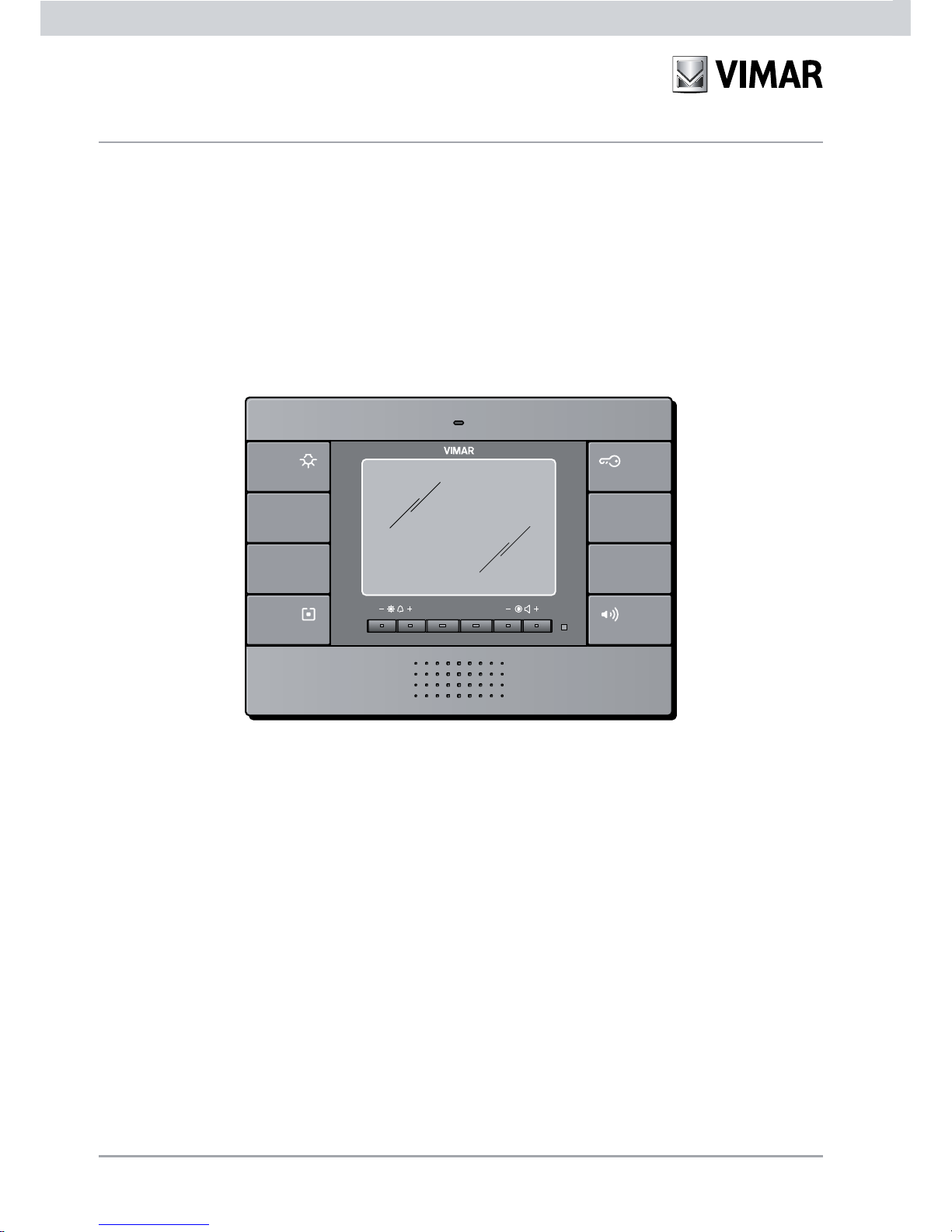
The DigiBus surface mounting video door entry unit permits audio-video interfacing through which communication
is possible between the device and the outdoor station; the video door entry unit is equipped with inputs and
outputs that enable connecting up with the other system appliances (power supply, electric lock relay, etc.).
Technical characteristics
Figure 1 - Video door entry unit 01954, 01954.14, 01954.20.
Page 5
3
Type of system.
The video door entry unit can only be used on ELVOX video door entry systems of the DigiBus digital type. It will
therefore be necessary to use solely ELVOX power supplies in the DigiBus range (for the specifications see the
relevant ELVOX manuals).
To accomplish the audio function, the type of connection towards the pillar has “4 wires” (plus the power supply):
- Digital line;
- Digital line power supply;
- Voice unit;
- Ground;
- Power supply (positive);
- Power supply (negative).
To accomplish the video function (integrated with the audio portion) a video camera must be installed on the
outdoor station and the video connection then needs to be wired towards the pillar:
- Video signal.
- Video signal ground.
The DigiBus system enables creating types of systems where device and control identification is digital.
Depending on the system configuration, each of the connected devices has a numerical code with 4 or 8 digits
(which must be univocal) and is able to receive and send the data packets that contain all the information relating
to communication management. Each data packet is composed of identification of the destination device and the
command that this device must carry out.
All the typical control operations of a video door entry system such as, for instance, call, electric lock opening,
switching on stair lights, etc., are therefore all coded.
Whereas, the voice unit for voice communication and the video signal to see the images are signals that remain
analogue.
As regards the type of cables to use for the connection between the system components, both towards the pillar
and towards the outdoor station, you are advised to refer to the following table and the diagrams illustrated in the
"INSTALLATION DIAGRAMS AND EXAMPLES" chapter:
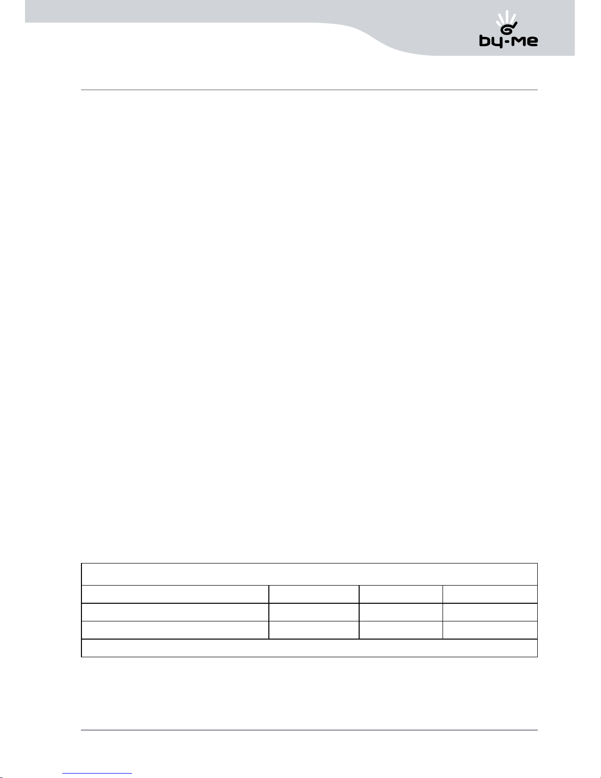
CONDUCTOR MINIMUM CROSS-SECTION (mm2)
TERMINALS Up to 50 m Up to 100 m Up to 200 m
-, +, LOCK, +T, C1, C2 1 mm
2
1.5 mm2 2.5 mm
2
OTHERS 0.75 mm
2
1 mm2 1.5 mm
2
VIDEO: 75 Ohm coaxial cable (type RG59) or RG11 with double insulation
Technical characteristics
Page 6
4
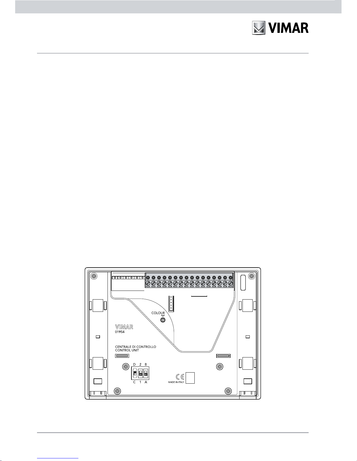
Description of terminals.
The video door entry unit has a 16-pin connector for connecting the audio and video signals, power supplies, calls
and all the optional functions (fig. 2).
Advantages of the DigiBus system.
The most important advantage offered by the DigiBus system compared to a classic analogue video door entry
system (8 wires + n) is the “saving” (on the pillar side) of the single call wire for each indoor station (necessary, on
the contrary, in the classic analogue system).
Thanks to this feature, the system is ideal to be used in installations where there are many indoor stations (for example, large building complexes) since it considerably simplifies wiring operations, because the number of cables
is always the same irrespective of the number of indoor stations to install:
- audio door entry system: 4 wires (plus 2 for the power supply).
- video door entry system: 8 wires (including the power supply).
Another advantage of using the DigiBus system is the extreme flexibility for future expansion of the system; it is
indeed possible to add new indoor stations by simply using the pillar without having to connect additional cables
to the power supply.
Digital management of all the commands (call bell duration, bell type, call time duration, answer time duration,
access via password or programmed key, etc.) lastly enables programming all the parameters of the devices according to the different needs of each user.
Technical characteristics
Figure 2
V3 M V1 13 12 11 10 9 8 7 6 5 4 3 2 1
Page 7
5
The connector, pillar side, through which all the connections from and to the video door entry unit are made, has
16 terminals (inputs and outputs) divided according to the functions given in the following table:
Terminal number Type Function
1 Input/Output Digital line
2 Input/Output Secondary voice unit on door outside
3 Input/Output Main voice unit on the pillar
4 - Ground
5 - Digital line power supply + 13.5 V d.c.
6 Output Supplementary bell
7 - Power supply (-)
8 - Power supply (+)
9 Input Call from outside the door
10 Output Video distributor power supply (12 V d.c.)
11 Input External function F1
12 Input External function F2
13 Input Green LED for “door open” signal
V1 Input Coaxial video signal
M - Video signal ground
V3 Input Pair video signal
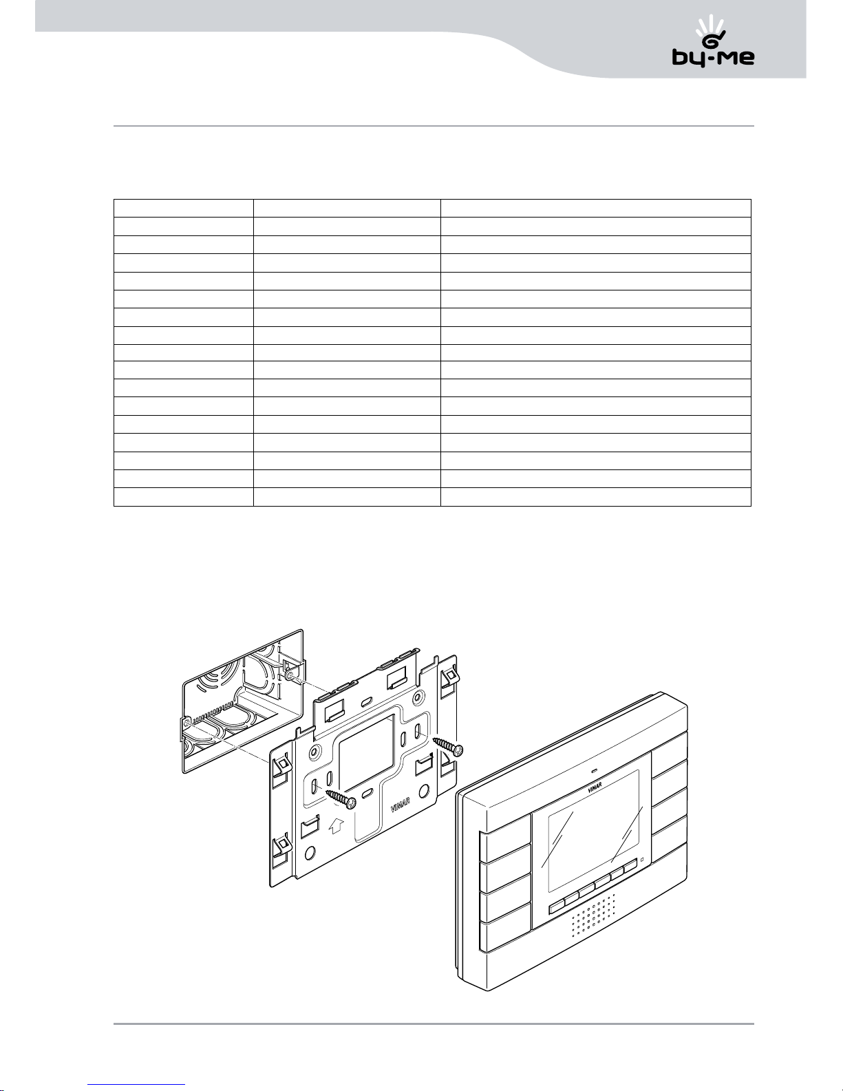
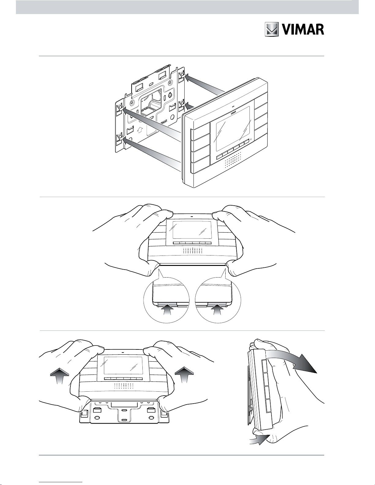
The video door entry unit must be installed with the procedure illustrated in figure 3; if the device has to be removed
from the wall (maintenance, etc.), unhook the front panel from the metal bracket (see figures 4, 5 and 6).
It is recommended to hook the video door entry unit to the bracket before powering up the system, making
sure that the mechanical coupling is perfect.
Technical characteristics
UP
Figure 3 - Installing the video door entry unit
Page 8
6
Technical characteristics
UP
Figure 4 - Hooking onto the bracket
Figure 5 - Unhooking from the bracket
Figure 6 - Removing the video door entry unit
Page 9

7
Power input.
The consumption of the video door entry unit depends on the current operating mode of the device (standby, on
call, red/green LED on, control activation, etc.).
The average values of the power input in the three typical operating modes are the following:
- on standby 15 mA.
- on call 200 mA.
- with monitor on 150 mA.
N.B. The above values are given as a guideline.
Operation of the ELVOX DigiBus system.
The ELVOX DigiBus system permits digital coding of the devices and commands that are sent or that come from
the external plate; the latter can be considered as the master device (main appliance governing communication
between the digital devices in the system), while every other single digital device can be considered as a slave
(secondary appliance that is piloted/controlled by the master).
The external plate is therefore absolutely essential for operation of the DigiBus system and must always
be installed in the system. All the programming parameters (call time, type of bell, electric lock opening, code
numbers of the indoor stations, etc.) are set and stored (until the next programming) in the main external plate
(EEPROM memory).
NOTE: Alternatively to the outdoor plate there are other master devices such as, for example, the consumer unit in
the porter's lodge, the consumer unit on EN 50022 rails for PC, etc. (see the ELVOX DigiBus catalogue).
For programming the plate and all the parameters correlated with it, see the relevant ELVOX technical literature.
The communication protocol used by the DigiBus system is proprietary ELVOX and is “serial-similar” with active
level at 12 V d.c. (0 V d.c. at rest) and communication input on the digital line of 25 mA (current limiter on plate).
The standard speed is 600 b/s that enables reaching distances on the digital bus of a few kilometres.
Compatible ELVOX power supplies.
The power supplies that can be used for installing the system are all those in the ELVOX DigiBus range; in particular
the following articles are recommended:
• 6948 (standard video door entry unit power supply).
• 6947 (supplementary power supply for monitor and call signal).
• 6942 (supplementary power supply for plates, consumer unit and video distributors).
For all the technical characteristics (power supply voltage, current delivered, absorption, description of terminals,
etc.) see the ELVOX technical manuals.
Technical characteristics
Page 10

8
General information on the digital commands
The digital commands are data packets that can be sent by every digital device containing the information/in-
structions that enable activating a particular function (unlocking, switching on stair lights, activating auxiliary function, etc.) by means of an actuator.
Typically, in the DigiBus system, the main commands are the following:
- LOCK command that controls the actuator S1
- CALL-F1 command that controls the actuator R1
- CALL-F2 command that controls the actuator R2
The actuators can be relays or voltage generators in the power supplies that are controlled by master devices
(plates or consumer units) after receiving the data packet containing the command to actuate.
In the case of the main commands listed above (and with reference to the DigiBus power supply 6948) the actuators are the following:
- actuator S1 Relay →
the contact S1 closes to 0 (ground) on receiving the command.
It is used to open the electrical lock via the power supply on terminals no. 15 and 0.
- actuator R1 Voltage generator 12 V d.c. (max 150 mA) → active on receiving the command.
It is used to control an auxiliary external relay (e.g. switching on stair lights).
- actuator R2 Voltage generator 12 V d.c. (max 150 mA) → active on receiving the command.
It is used to control an auxiliary external relay (e.g. supplementary acoustic repeater).
Each single command is sent by pressing a button (associated with the command) on the device. Other commands can be associated with other buttons that may be present.
List of standard commands:
CALL-PLATE+TLC Call from plate with video camera activation.
CALL-PLATE Call from plate without video camera.
CALL-AUDIO DOOR ENTRY UNIT Call from audio door entry unit.
LOCK Unlocking.
CALL-F1..F8 Call functions F1..F8.
CALL-CONSUMER UNIT Call from consumer unit.
Additional technical and installation details are given in the “FUNCTIONS OF THE VIDEO DOOR ENTRY UNIT”
chapter and the attached diagrams “INSTALLATION DIAGRAMS AND EXAMPLES”.
Technical characteristics
Page 11
9
The main function of the device is, by communicating over the audio and video channels, to identify anyone wanting to enter the dwelling by using the outdoor station and to open the electrical lock of the gate or door when
appropriate.
In addition, the video door entry unit enables additional functions that are:
- turning on stair lights;
- self-start outdoor station;
- additional auxiliary function.
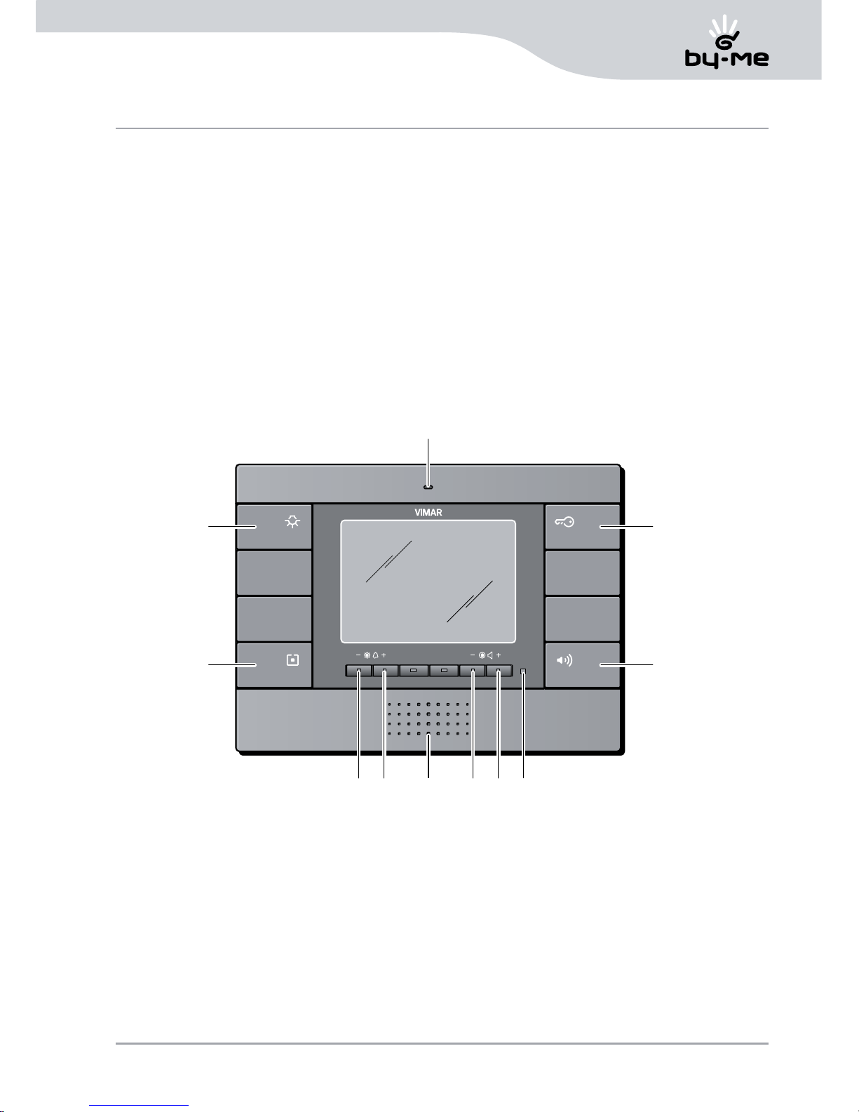
All the functions of the video door entry unit are enabled by pressing the dedicated buttons.
The main operating states of the video door entry unit are the following:
- With MONITOR ON (the LCD monitor and the backlighting LEDs of the buttons are on).
- With MONITOR OFF (the LCD monitor and the backlighting LEDs of the buttons are off).
A CALL-F1 command button.
B LOCK command button.
C CALL-F2 command button or 2ndf .
D Speakerphone answer button.
G Microphone.
E-F Buttons controlling brightness and
Configuration.
H-I Buttons controlling volume, contrast.
of the video and Configuration.
L Indicator LED.
M Speaker.
Functions of the video door entry unit
Figure 7 - Front view of the video door entry unit.
E F
M
H I
B
G
D
A
C
L
Page 12

10
Video signal cable selector.
The selector on the back of the video door entry unit by the letters "DC", depending on the type of video signal
used, permits selecting the most appropriate mode to reduce interference on this signal.
The selector, shown in the figure with V1, permits two different settings depending on whether the video signal
from the outdoor station is wired with coaxial cable (polarized video signal) or, alternatively, with a twisted pair
(differential video signal).
V1 in position “D” = twisted pair (connect the terminals V1 and V3)
V1 in position “C” (default position) = coaxial cable 75 Ω (connect the terminals V1 and M)
Functions of the video door entry unit
C
D 2 B
1 A
Figure 8 - Configuring V1 selector
V1
Selector V1
C
D 2 B
1 A
Page 13

11
The “Second Function” button (2ndF) and type of unit outside the door.
Sending the main commands CALL-F1, CALL-F2 and LOCK is controlled by pressing the related buttons of the
video door entry unit A, C and B.
The system moreover enables sending additional commands of “auxiliary functions” that can be used, for example, to govern cyclical viewing of a number of indoor video cameras, unlocking from the landing or other auxiliary
devices, switching on stair lights, etc.; to be able to use these commands it is necessary to configure button C of
the video door entry unit as the “second function” button (2ndf).
To do this you need to put selector S1, which is on the back of the video door entry unit by the numbers "1 2"
(see following figure), onto position 2.
To set the type of unit outside the door (as preferred between “AUDIO” outside the door or “DOORBELL” outside
the door) it is necessary to set selector S2 as indicated below.
Functions of the video door entry unit
S1 on position 1 (default position) = button C (direct command CALL-F2).
S1 on position 2 = button C (2ndF).
Figure 9 - Configuring 2ndF button and
type of unit outside the door button.
S2 in position A (default position) = “AUDIO” outside the door.
S2 in position B = “DOORBELL” outside the door.
WARNING!
The setting for selectors S1 and S2 is done at the time of installation.
C
D 2 B
1 A
C
D 2 B
1 A
S1
S2
Button 2ndF
Page 14

12
Button 2ndF, pressed in combination with other buttons, sends additional separate supplementary commands
on the digital line ranging from CALL-F3 to CALL-F8.
When the button C is configured as 2ndF the command – button correspondence is the following:
LOCK Pressing button B
CALL-F1 Pressing button A
CALL-F2 Pressing buttons C+A
CALL-F3-F4-F5 Pressing buttons C+E (cyclic)
CALL-F6 Pressing buttons C+F
CALL-F7 Pressing buttons C+H
CALL-F8 Pressing buttons C+I
LOCK-LANDING
(analog type command) Pressing buttons C+B
Note: The command-button-function combinations are also given in the “FAST GUIDE TO USING THE VIDEO
DOOR ENTRY UNIT” section.
The following are the procedures for activating the functions of the video door entry unit once it has been connected in an ELVOX DigiBus video door entry system.
Functions of the video door entry unit
Figure 10 - Button release
Numerical coding of the video door entry unit.
The Digibus video door entry unit is identified in the system
with a numerical code with 4 or 8 digits (parameter to set on
the DigiBus plate); it is then necessary to do the programming
for this code by carrying out the following procedure:
• Unhook the button cover of button C
(control function CALL-F2);
Page 15

13
• Using a screwdriver or small tool, briefly press the push-button R under button D (figure 11);
• Press and hold down button B for at least 5 seconds (door-opening function) (figure 12);
• The red LED of the video door entry unit lights up confirming that the device is ready to be coded.
• Send a call to the video door entry unit with the desired numerical code; if you have a plate with an alphanumeri-
cal keypad it is sufficient to key in the code and send it to the device by pressing button “C” on the plate.
• Programming the video door entry unit with the desired code is confirmed by the red LED going out on the
monitor and by an audible confirmation signal on the plate.
• Lastly, check that the video door entry unit answers the call (with the alphanumerical plate key in the set code
and press button “C” on the plate).
If you do not have a plate with an alphanumerical keypad or with single buttons you need to use the specific
ELVOX programmer or a PC with a serial interface and ELVOX software (see the “PROGRAMMING THE DigiBus
PLATE”).
Functions of the video door entry unit
Figure 12
Figure 11
R
Page 16

14
Call answering.
When a call is made from an outdoor station (external plate or consumer unit), the video door entry unit related to
the called numerical identification modulates the programmed call tone on the speaker; the video door entry unit
then emits an audible warning and, if the video signal has been connected as well, the LCD monitor lights up to
display the person calling.
Since it is a speakerphone system, to answer the call and communicate with the outdoor station it is necessary to
press the answer button D (fig. 6) and keep it pressed throughout the entire conversation.
The time for inserting the call is set as the plate parameter; these parameters can all be set at the time of programming the outdoor plate (master) and concern various functions such as timing, recording users, etc. (For a full list
of parameters see the ELVOX technical literature for the plate used and refer to the “MAIN CONFIGURATIONS”
chapter as well).
Self-start function.
This function is used to activate the audio and video communication on the outdoor station without a call being
received; this function may be useful, for example, to check the area outside
The self-start function activates only if button C is configured as 2ndF (see “The second function button (2ndF) and
type of outside the door” section); having done this, to activate the self-start on the outdoor plate it is necessary
to send one of the following commands:
• CALL-F3
• CALL-F4
• CALL-F5
Pressing button E a number of times in succession (always keeping button C pressed) sends the commands
CALL-F3, CALL-F4 and CALL-F5 cyclically as well.
If the self-start function is enabled on the plate and the related numerical parameter is set, on receiving the sent
command the plate self-starts on the calling video door entry unit (for the plate programming details relating to this
function see the “MAIN CONFIGURATIONS” – Programming DigiBus plate (basic notions) section).
Confidential Conversation.
The “Confidential Conversation” function is used to communicate with the outdoor station only if a call has
arrived or there has been a self-start. It is not possible to listen to other communications in progress or self-start
while a conversation is in progress.
In DigiBus systems the “Confidential Conversation” function is always enabled.
NOTE: The voice unit towards outside the door is always on.
Functions of the video door entry unit
Page 17

15
The additional power supply is typically necessary for systems in building complexes where numerous video door
entry units co-exist.
For single dwellings or small apartment blocks, where up to 10 video door entry units can be installed of which
at most 2 in parallel, it is possible to use the auxiliary power supply output of the main power supply e.g. 6948
terminals 15 – 0 output 15 V d.c.); if there are more video door entry units it is necessary to use the additional
power supplies (ELVOX 6582 15 VA 13.5 V d.c., one for every 30 additional video door entry units).
“Door open” signal.
This function is used to display a “Door Open” signal on the video door entry unit by lighting up a green LED on
the right-hand side of the LCD monitor; this application is useful to prevent unwanted access to the dwelling.
The wiring to enable the function is made by using terminal 13 of the 16-pin connector; it is moreover necessary
to carry a voltage of 12 V d.c. via a N.O. contact that, inserted in the lock, closes when the door is open and, at
the same time, lights up the green LED on the monitor (average additional consumption 10 mA).
Example of installation:
“Door open” signal powered with additional ELVOX power supply 6582 15 VA (13.5 V d.c.).
Functions of the video door entry unit
Figure 13 -
Connection of the “open door”
signal with additional power supply.
01954
01954.14
01954.20
V3
M
V1
13
12
11
10
9
8
7
6
5
4
3
2
1
PRI
D
V
1
2
3
S
+
15/AS
S/S1
V 1 3 4 5 - + C
CBA
+I+U
-
Network
Lock N.O.
contact
Power supply
Art. 6582
Video door
entry unit
Page 18

16
Lock control activation.
This control activates the lock opening relay of the door or gate providing access to the dwelling.
The command is carried out by pressing button B that sends the LOCK command to the plate which activates
the lock opening relay in the power supply; this output can pilot electrical locks at 12 V a.c. max 1 A (for example
ELVOX power supply 6948 terminals 15 – S1).
For electrical locks with greater power inputs use an external relay.
The lock command is activated solely with the MONITOR ON (self-start or call in progress).
For the wiring of the control see the diagrams in the attached “INSTALLATION DIAGRAMS AND EXAMPLES”.
Stairs light control activation.
With this command it is possible to activate the output used to control an appropriate external relay connected
to one or more lamps to switch on.
The command is activated by pressing button A that sends the CALL-F1 command to the plate which activates
the output R1 of the power supply that can be used to enable an external auxiliary relay (to be fitted).
For loads powered at 230 V it is recommended to use relays with 12 V d.c. or 15 V a.c. with output 230 V a.c.
3 A.
The stairs lighting control is always active in both operating states MONITOR OFF and MONITOR ON respectively.
NOTE: The command CALL-F1 can be remoted with a N.O. push-button by using terminals 4 and 11 of the
16-pin connector.
Figure 14 - Connection for stair light with load connected on relay output R1 and command F1.
Example of installation:
Wiring of ELVOX external relay
170/001 12 V d.c. (15 V a.c.)
230 V a.c. 3 A for switching on
stairs lights.
Functions of the video door entry unit
1 2 3 4 51
V 1 3 4 5
F1 F2
- +
Power supply
Art. 6948
Network
To the plate or consumer unit
Additional
function
“F1“
Additional
function
“F2“
Relay
Art. 170/001
Relay
Art. 170/001
2 3 4 5
Page 19

17
Auxiliary Function activation.
The Auxiliary Function activation control can be used to activate external devices or services such as, for instance,
courtesy lights, automation, etc.; this is possible by hooking up a suitable external relay at 12 V d.c. or 15 V a.c.
and a contact that depends on the service you want to activate.
The auxiliary function is activated by pressing button C that sends the CALL-F2 command to the plate which
activates the output R2 of the power supply that can be used to enable an external auxiliary relay (to be fitted).
For loads powered at 230 V it is recommended to use relays with 12 V d.c. or 15 V a.c. with output 230 V a.c.
3 A.
The auxiliary function activation command is always active in both operating states MONITOR OFF and MONITOR
ON only if button C has not been configured as button 2ndf, or with the combination of buttons C+A (see
page 11).
NOTE: The command CALL-F2 can be remoted with a N.O. push-button by using terminals 4 and 12 of the
16-pin connector.
Figure 15 - Connection for auxiliary function with load connected on relay output R2 and command F2.
Example of installation:
Wiring of ELVOX external relay
170/001 12 V d.c. (15 V a.c.)
230 V a.c. 3 A for switching on
stairs lights.
Functions of the video door entry unit
1 2 3 4 51
V 1 3 4 5
F1 F2
- +
Power supply
Art. 6948
Network
To the plate or consumer unit
Additional
function
“F1“
Additional
function
“F2“
Relay
Art. 170/001
Relay
Art. 170/001
2 3 4 5
Page 20

18
Call from outside the door.
Via the wiring of the dedicated terminal it is possible to differentiate the sound of a call from the button outside the
door (for example, landing, secondary entrance, etc.) to distinguish it from a call from the outdoor station.
To differentiate the call from outside the door the corresponding input (terminal no. 9) is used on the 16-pin connector and the voice unit line dedicated to outside the door (terminal no. 2).
Alternatively, this input can be used in the “DOORBELL” configuration using a N.O. push-button connected to
terminals 9 and 5 on the 16-pin connector and setting the correct type of outside the door (see page 10).
For more details see the “Main Configurations” and “Installation Examples” section.
Example of installation
Figure 16 - Connection for the call from outside the door.
AUDIO Configuration DOORBELL Configuration
Functions of the video door entry unit
01954
01954.14
01954.20
20576 / 14576
Landing
call button
Video door
entry unit
Push-button
1 P N.O.
01954
01954.14
01954.20
Video door
entry unit
Page 21

19
Functions of the video door entry unit
Installation of supplementary external bells.
If it is necessary to transmit the audible call warning to different points of the system (large properties, etc.) or boost
its loudness, it is possible to install external bell repeaters.
This requires using terminals no. 6 and 5 of the 16-pin connector.
Example of installation:
Installation of external drum
bell with ELVOX external relay
170/101 and load at 230 V a.c.
max 3 A.
Figure 17 - Installation of supplementary external bells.
V1
M
V3
13
12
11
10
9
8
7
6
5
4
3
2
C 1 2 15 RC 3 4 5
1
Drum bell
Bell
power supply
Relay
Art. 170/101
01954
01954.14
01954.20
Video door
entry unit
Page 22

20
In practice there are different installation topologies for making video door entry systems; the type of each system
depends on the structure of the building, the number of indoor and outdoor stations you want to install and on
the functions to enable.
The most frequent diagrams are typically ones where there are one or more outdoor call stations and one or
more indoor response stations; the diagram with a single outdoor station uses a single power supply per pillar
while the installation of more than one outdoor station, in addition to one power supply per pillar, has audio-video
signal switch modules.
The diagrams then differ according to the functions and services required (connection of a number of video door
entry units in parallel, etc.) for which specific supplementary modules must be added (for example video distributors, supplementary power supplies, etc.).
Figures 18 and 19 show the installation diagrams for the simplest configurations:
Figure 18 - Single outdoor station.
Installation topology
Video door entry units pillar
6
77
7
7
6
6
2
10
A
B
F
C
G
C
01954
01954.14
01954.20
Video door entry unit
01954
01954.14
01954.20
Video door entry unit
Page 23

21
The wiring diagrams of figure 20 show a single power supply from the pillar (B) in systems using the single outdoor
station (A), whereas when there are a number of outdoor sources of the audio-video signal (outdoor stations with
video camera and voice unit) it is necessary to add additional modules:
• video switching relay (D);
• additional power supplies (F);
• video distributors (H)
Both VIMAR and ELVOX (C) indoor stations can be installed in the pillar provided they belong exclusively to the
DigiBus range.
For the technical details on the possible installation topologies in both “simple” residential and in complex building
structures, see the examples shown in the attached diagrams “INSTALLATION DIAGRAMS AND EXAMPLES”.
Figure 19 - Multiple outdoor station.
Installation topology
101111
6
2
DDEC
B F
A
G
Additional plate
2
A
G
2
A
G
Video door entry units pillar
Page 24

22
Figure 20 - Multiple outdoor station and Plates at the bottom of the stairs.
Installation topology
2
A
I
A1 A2
2
B
A3 A4
B
I I
H
G
F E C D
ECD
2
6
10
6
10
3 3
3
2
1
333
3
9 9 8
2
I
2
I
Additional plate
Video door entry units pillar Video door entry units pillar
Page 25

23
All the main functions of the video door entry unit seen in the “FUNCTIONS OF THE VIDEO DOOR ENTRY
UNIT” chapter are configured using the buttons on the front of the device (see fig. 3).
Depending on the operational status of the monitor (ON OR OFF) it is possible to set and program different
functions that are as follows:
Self-start function enabling.
To enable this function you need to configure the plate so it can receive a digital self-start command (typically
selectable from CALL-F3, CALL-F4 or CALL-F5); to enable the self-start parameter on the plate for the desired
command, see the “PROGRAMMING THE DigiBus PLATE (BASIC NOTIONS)” section.
After the plate has been enabled you need to set the video door entry unit so it can send the digital self-start
command; this can be done both with the MONITOR OFF and with the MONITOR ON:
• At the time of installation, enable button C as 2ndF (second function).
• Keeping button C pressed, press button E at successive intervals (press - release - press - release). In this way
the commands CALL-F3 , CALL-F4 and CALL-F5 are sent cyclically and the plate self-starts on receiving the
command programmed as the self-start command.
If more than one video source is installed, it is helpful to run the command cycle so as to pass the picture between
video cameras.
WARNING! The self-start function can only be used if button C is set as 2ndF.
Confidential conversation enabling.
In the Digibus system, Confidential Conversation is always enabled.
Configuring the vide door entry unit
Page 26

24
“User away” function enabling.
This type of function allows the user, via the external plate, to signal his/her absence to the consumer unit (where
applicable); in addition it can also be used when the user is present but does not want to be disturbed.
When this function is enabled, the video door entry unit receiving the call emits no audible warning, but sends the
“user away” command to the consumer unit (where applicable).
To enable the User-Away function, with the MONITOR OFF, carry out the following operations:
• Press buttons F and I for approximately 3 sec; the red LED will start to blink.
• Press button D; the red LED goes out and the function is activated.
To disable the function, with the MONITOR OFF, carry out the following operations:
• Press buttons E and H at the same time for approximately 3 sec; the red LED will start to blink.
• Press button D; the red LED goes out and the “User-Away” function is deactivated.
The red LED goes out after each programming phase or after a time-out of approximately 15 sec; if the LED goes
out because of a time-out it is necessary to repeat the configuration.
Red LED signals.
When the "User-Away" function is enabled, the LED gives the following information:
• LED on steady = "User-Away” function enabled.
• LED blinking = Call received (the LED emits up to 4 fast blinks to distinguish up to 4 different calls).
Configuring the vide door entry unit
Page 27

25
Activation of monitor switch-on by call from outside the door.
If there is an outdoor station outside the door with a video camera, the video door entry unit must be configured
so that on receiving a call the monitor switches on (besides obviously enabling the voice unit).
To enable switching on the monitor from outside the door, with the MONITOR OFF, carry out the following operations:
• Press buttons F and I at the same time for approximately 3 sec; the red LED will start to blink.
• Press button C; the red LED goes out and the switch-on function is activated.
To disable the function, with the MONITOR OFF, carry out the following operations:
• Press buttons E and H at the same time for approximately 3 sec; the red LED will start to blink.
• Press button C; the red LED goes out and monitor switch-on from outside the door is deactivated.
The red LED goes out after each programming phase or after a time-out of approximately 15 sec; if the LED goes
out because of a time-out it is necessary to repeat the configuration.
Notes:
• In the case of switch-on enabling the monitor stays on for at most 60 seconds.
• By default, the function of activation of monitor switch-on by call from outside the door is disabled.
Setting the command associated with the call from outside the door.
To swap over the video signal from the source on the plate to an alternative source (for example an outdoor station
outside the door with a video camera) it is necessary to pilot a video exchange digital relay (type ELVOX 170F +
170/051) with a specific command.
The command is sent from the video door entry unit to the digital relay that will enable the video exchange if the
call is made from outside the door; the digital activation commands that can be used are CALL-F6, CALL-F7 or
CALL-F8.
To associate the desired command with the call from outside the door, carry out the following procedure:
• Set button C as 2ndF.
• Press buttons H and I at the same time for at least 3 seconds and with the monitor off; the red LED will start
to blink.
• Press the combination related to the chosen command (for example C + F if you want CALL-F6), the red LED
will go out.
The red LED goes out after each programming phase or after a time-out of approximately 15 seconds; if the LED
goes out because of a time-out it is necessary to repeat the configuration.
Note:
• The command set by default is CALL-F6.
Configuring the vide door entry unit
Page 28

26
Selecting bell type.
It is possible to select the types of bell to combine with the different calls that the video door entry unit can
receive:
- call from plate;
- call from outside the door.
Setting the plate bell.
The bell for calls from the plate is selected as follows:
• With the MONITOR OFF, press button E or button F for at least 3 seconds to access the list of available
tones.
• Using button E or button F, scroll through the list of tones, the video door entry unit will play the related bell
and save it in correspondence with the input of the call from plate (upon saving, the red LED will light up for a
few moments).
Setting the bell from outside the door.
To select the type of bell for calls from outside the door it is necessary, with the MONITOR OFF, to carry out the
following operations:
• Press buttons E and F at the same time for approximately 3 sec to access the list of available tones; the red
LED will start to blink.
• Using button E or button F, scroll through the list of tones; the video door entry unit will play the related bell
and save it in correspondence with the input of the call from outside the door and the red LED will go out.
The red LED goes out after each programming phase or after a time-out of approximately 15 sec; if the LED goes
out because of a time-out it is necessary to repeat the configuration.
Bell volume adjustment.
The volume adjustment of the bells that have just been described is done in a similar manner for all types of call
(from outdoor plate and from outside the door).
The adjustment, to be made with the MONITOR OFF, is set as follows:
• Press button H for at least 3 sec to decrease the loudness of the bell;
• Press button I for at least 3 sec to increase the loudness of the bell.
Speakerphone volume adjustment.
With this procedure it is possible to adjust the volume of the audio channel that is transmitted from an outdoor
station to the speaker of the video door entry unit.
The adjustment, to be made with the MONITOR ON and keeping button D pressed, is set as follows:
• Press button H to decrease the loudness;
• Press button I to increase the loudness.
Configuring the vide door entry unit
Page 29

27
Configuring the vide door entry unit
Note: The colour adjustment is the less
critical one that has the least effect on the
quality of the picture on the LCD monitor
with respect to changes in ambient light.
Setting brightness.
To set the level of brightness of the LCD monitor, it is necessary, with the MONITOR ON, to carry out the following
operations:
• Press button E to decrease the brightness;
• Press button F to increase the brightness.
Setting contrast.
To set the level of contrast of the LCD monitor, it is necessary, with the MONITOR ON, to carry out the following
operations:
• Press button H to decrease the contrast;
• Press button I to increase the contrast.
Figure 21 - Colour adjustment.
Setting colour.
The colour adjustment is made with the
trimmer on the back of the device by
the words "COLOUR" (see figure 21);
it is therefore necessary to make the
adjustment before installing the video
door entry unit on the wall.
After installing the appliance on the wall
with a flush mounting box it will no longer
be possible to get to the trimmer except
by again removing the video door entry
from the fixing bracket.
Video parameter adjustment.
With the following procedures it is possible to set the three parameters that govern the video picture on the LCD
monitor:
- brightness;
- contrast;
- colour.
Page 30

28
WARNING! The following steps must be carried out after powering up the system and before programming
the audio and video door entry units.
The plate parameters can be configured in three different ways:
• Directly from the plate using the alphanumeric keypad or single buttons.
• Via the specific ELVOX programmer 950B.
• Using a PC with ELVOX serial interface 6952 and ELVOX software “PC Digibus ANALYZER”.
This section illustrates solely the method of programming with the alphanumerical keypad on the front of the
DigiBus plate; for configuring with the programmer or PC refer to the relevant ELVOX technical literature.
To access the plate configuration menu, carry out the following steps:
• Press buttons R and 4 at the same time.
• Enter the password providing access to programming; key in “0123” for the first configuration (default password
set in the factory that must then be changed by the installer).
• Press button C to confirm.
It is now possible to scroll through the list of all the plate parameters and related settings; for each one of these
parameters a value can be entered that identifies the parameter and the related configuration.
The set values must come within a certain range (minimum value - maximum value) as stated in the parameters
table attached to the plate technical literature (see, for example, the “PLATE TECHNICAL PARAMETERS” table
illustrated on the following pages).
• Press button C a number of times to scroll through the list of available parameters.
• Using the alphanumerical keypad, enter the value related to the parameter to be set.
• Press button C to confirm.
• Press button R to end programming.
To configure DigiIBus plates with no alphanumerical keypad, refer to the relevant ELVOX technical literature.
Programming the DigiBus plate
Page 31

29
No.
Parameter
Abbreviation
on the display
of the Italian
programmer
Minimum
value
Maximum
value
Default Description
When to change
the value
1 Initial user Utente iniziale 1 99999999 1
Minimum call number (filter on codes in transit
from terminal 6 to terminal 1).
It is required in building
complexes.
2 End user Utente finale 1 99999999 99999999
Maximum call number (filter on codes in transit
from terminal 6 to terminal 1).
It is required in building
complexes.
3 Plate code Numero targa 0 99999999 0
Plate call/identification number (for calls/analysis from consumer unit).
In systems with porter's
lodge consumer unit with
a number of electronic
plates
4
Sum
Number
Numero
Somma
0 99999999 0
Changes call code by summing the value
of the buttons with the value entered in the
parameter. It only takes effect when parameter
26" enabling Software coding" is 0.
It is optional, it permits
translating the values of
all the buttons without
changing them one
by one.
5 Spare Spare.
6 Spare .................... Spare
7
Buttons in
two rows
Abil. Tasti
Doppi
0 1 0
Indicates the type of push-button configuration: in a single row
(=0) or in two rows (=1).
It is to be programmed
according to the
modules.
8
Coding
system
Numero Cifre 4 8 8 Selects system with 4 or 8 Digits.
For systems with 4-digit
coding, set the value
to 4.
9 Language Lingua Inglese 0 1 0
To be used with the programmer art. 950B
(0= Italian, 1 = English).
It is optional.
10 Plate Block Blocco Targa 0 1 0
Disables operation of the plate
(0 = No, 1 = Yes).
It is optional.
11
Enables
priority
Abilita priorità 0 1 0 Plate with priority (0 = No, 1 = Yes).
It is optional but only for
plates in parallel.
12
Enables
sequential
lock
Abilita
serratura
0 4 1
Enables lock activation.
0 = The lock is only activated by the audio
door entry unit called by the corresponding plate.
1 = The lock is activated in sequence with that
of a main plate. The plate must be between
the main plate in relation to the plate.
2 = The lock is activated by a consumer unit
that is the main one with respect to the
plate.
3 = Enables both points 1 and 2.
4 = The lock is activated in any case even
when the audio door entry unit has not
been called.
6 = Function 4 + function 2.
It is optional.
13
Enables
video
camera
Abilita telecam. 0 1 1
Indicates whether the plate has a video
camera
(0 = No, 1 = Yes).
It is required with plates
supplied with an indoor
or outdoor video camera.
14
Enables
sound at the
plate
Abilita suono
Ta .
0 1 1
Enables repeating the call sound at the plate
(0 = No, 1 = Yes).
It is optional.
Example of plate technical parameters
Page 32

30
No.
Parameter
Abbreviation
on the display
of the Italian
programmer
Minimum
value
Maximum
value
Default Description
When to change
the value
15
Enables
self-start
Abil. Autoaccen.
0 7 0
Enables self-start of the video/audio door entry
unit via commands F3, F4 and F5). Add together the values of F3, F4 and F5 to indicate
what functions enable self-start
(0 = No, 1 = F3,2 = F4 and 4 = F5).
With 7=1+2+4 it self-starts with F3, F4 and F5.
It is optional.
16
Enables
intercom
Abil. Intercomu.
0 1 0 Not available. Not available.
17 Spare ..................... Spare.
18
Button for
calls to
consumer
units
Tast. Chiam.
Centr
0 255 0
Assigns the button to call the consumer unit,
when the consumer unit is the main one with
respect to the plate.
It is optional.
19 Call time
Durata
Convers.
1 255 12
Maximum call time
(in seconds for 10, 12=120 seconds).
It is optional.
20 Bell time
Durata
suoneria
1 255 1 Time to activate the call signal (in seconds). It is optional.
21 Answer time
Tempo
risposta
1 255 30 Maximum time awaiting answer (in seconds).
It is required in building
complexes.
22
Function
time F1
Tempo Funz. 1 0 255 1
F1 function activation time (in seconds).
If set on 0 activation is reduced to 0.5 sec.
It is optional.
23
Function
time F2
Tempo Funz. 2 0 255 1
F2 function activation time (in seconds).
If set on 0 activation is reduced to 0.5 sec.
It is optional.
24 Lock time
Tempo
serratura
0 255 1
Lock activation time (in seconds).
If set on 0 activation is reduced to 0.5 sec.
It is optional.
25
End-of-conversation
warning
time
Tempo
preavviso fine
conversazione
0 255 0
End-of-conversation warning: after a call from
the plate with priority the existing communication receives a cut-off warning and stops after
the set number of seconds (0=no warning). If
set on 0 activation is reduced to 0.5 sec.
It is optional.
26
Enables
push-button
Software
coding
Abil. Num.
Sofwar
0 1 0
Enables coding the push-buttons in "Software"
mode.
Push-button coding is to be done with the
program art. 950B.
It is optional, but is to be
used with the programmer art. 950B
27
Enables
window
above
Abil. Finestra
Up
0 1 1
Enables the "initial user" - "end user" filter
also for data passing from terminal 1 towards
terminal 6 of the plate (0=No, 1=Yes).
It is optional but only for
building complexes.
28 Spare ..................... Spare
29
Parameter
reserved
Param.
Riservato
0 255 1
A password enables viewing the reserved
parameters.
Not to be used.
Note: In the table above there is the following correspondence:
F1 = CALL-F1 F3 = CALL-F3 F5 = CALL-F5 F7 = CALL-F7
F2 = CALL-F2 F4 = CALL-F4 F6 = CALL-F6 F8 = CALL-F8
Example of plate technical parameters
Page 33

31
Examples and installation diagrams.
The following examples give some diagrams that summarize the typical video door entry installations in the residential sector.
For the installation details see the diagrams in the following section.
Standard video door entry unit diagrams.
• Connection diagram with main video plate and indoor stations by Vimar.
• Connection diagram for monitor pillar with distributor on the landing.
• Connection diagram for monitor pillar with Elvox video door entry units and video/audio door entry unit by
Vimar.
Examples and installation diagrams
Page 34

32
Table of the functions of the buttons of the Vimar video door entry unit in Elvox Digibus systems.
A distinction is made between cases when the monitor is OFF and when it is ON, that is whether it is on after an
external call, from the plate or outside the door.
The green LED is not governed by the device, but is switched on by an external hardware connection.
SYSTEM DigiBus
Button
Pressed
Description:
Monitor OFF Monitor ON
A
Command F1
(F2 if C+A with 2ndF on)
Command F1
(F2 if C+A with 2ndF on)
B
Command CALL_AUDIO DOOR
ENTRY UNIT
(Landing Lock if C+B with 2ndF on)
LOCK command
(Landing Lock if C+B with 2ndF on
C
Command F2 or button 2nd Function
(2ndF) if the selector S1 is in pos. 2
Command F1 or button 2nd Function (2ndF) if the selec-
tor S1 is in pos. 2
D Talk-Listen Function Talk-Listen Function
E (-)
Plate bell type selection
(F3-F4-F5 if C+E with 2ndF on)
Brightness adjustment
(F3-F4-F5 if C+E with 2ndF on)
F (+)
Plate bell type selection
(F6 if C+F with 2ndF on)
Brightness adjustment
(F6 if C+F with 2ndF on)
H (-)
Bell volume selection
(F7 if C+H with 2ndF on)
Contrast
adjustment
Speakerphone Volume
adjustment if button D is pressed
(F7 if C+H with 2ndF on)
I (+)
Bell volume selection
(F8 if C+I with 2ndF on)
Contrast
adjustment
Speakerphone Volume
adjustment if button D is pressed
(F8 if C+I with 2ndF on)
E+F
Pressed simultaneously for 5 seconds with the monitor OFF takes you to programming the BELL FOR
LANDING CALL.
The red LED starts blinking and, within 15 seconds, you select the bell with button E or F. After programming (no longer pressing button E or F for 5 seconds or at the end of the time-out) the LED goes out.
H+I
Pressed simultaneously for 5 seconds with the monitor OFF takes you to programming the COMMAND
ASSOCIATED WITH THE VIDEO LANDING CALL.
The red LED starts blinking and, within 15 seconds, you select the call command with the combination of
buttons C + F/H/I (corresponding to F6/F7/F8 with 2ndF on).
After programming (no longer pressing buttons E or F for 5 seconds or at the end of the time-out) the
LED goes out.
F+I
Pressed simultaneously for 5 seconds with the monitor OFF, the red LED starts blinking and you perform:
- ACTIVATION USER AWAY FUNCTION pressing D
- ACTIVATION OUTSIDE THE DOOR MONITOR SWITCH-ON pressing C.
After the setting or, in any case, after the time-out of 15 seconds, the LED goes out.
E+H
Pressed simultaneously for 5 seconds with the monitor OFF, the red LED starts blinking and you perform:
- DEACTIVATION USER AWAY FUNCTION pressing D.
- DEACTIVATION OUTSIDE THE DOOR MONITOR SWITCH-ON pressing C.
After setting or at the end of the time-out (15 seconds) the LED goes out.
Fast guide to using the video door entry unit
Relay
Page 35

33
Installation Regulations.
Installation should be carried out observing current installation regulations for electrical systems in the country
where the products are installed.
Regulatory compliance.
EMC directive
Standards EN 61000-6-1, EN 61000-6-3
Installation Regulations - Regulatory compliance - Glossary
Glossary
Plate.
Set of audio and video devices that permit identifying the person requesting access to the dwelling via the outdoor
station.
Indoor station.
Single device, video or only audio door entry unit, that enables identifying the person at the outdoor station that
made the call.
Generally, besides communicating with the outdoor plate, the indoor station enables making other operations such
as unlocking, turning on stairs lights, etc.
Outdoor station.
General term used to indicate the plate or outside the door.
Pillar.
Term used to indicate the set of wirings connecting the indoor stations with the power supply.
Power supply.
Device that integrates the lock mechanisms, call generators and the necessary power supply towards both the
pillar and the plate.
Outside the door.
Set of audio and video devices that permit making a call towards the indoor station(s) and enable identifying the
person that made it.
It is generally installed for making calls from zones inside the building (landing, secondary entrances, etc.).
Self-start.
Optional function that permits audio and video communication between the indoor station and the plate or indoor
station and outside the door, without a call being received (from the plate or from outside the door respectively).
Page 36

907.1954A0.L.EN 01 0705
VIMAR - Marostica - Italy
Viale Vicenza, 14 - 36063 Marostica VI
Tel. +39.0424.488.600 - Fax: (Italia) 0424.488.188
http://www.vimar.eu
 Loading...