

Page 1

Instructions manual
01942
GSM-BUS communicator
Page 2

Page 3

1
Table of Contents
1. Description . . . . . . . . . . . . . . . . . . . . . . . . . . . . . . . . . . . . . . . . . . . . . . . . . . . . . . . . . . . . . . . . . . . . . . . . . . . . . . . . . . . . 2
2. Field of application . . . . . . . . . . . . . . . . . . . . . . . . . . . . . . . . . . . . . . . . . . . . . . . . . . . . . . . . . . . . . . . . . . . . . . . . . . . . . 2
3. Content of the package . . . . . . . . . . . . . . . . . . . . . . . . . . . . . . . . . . . . . . . . . . . . . . . . . . . . . . . . . . . . . . . . . . . . . . . . . . 2
4. Front view . . . . . . . . . . . . . . . . . . . . . . . . . . . . . . . . . . . . . . . . . . . . . . . . . . . . . . . . . . . . . . . . . . . . . . . . . . . . . . . . . . . . . 3
5. LED and push-button functions . . . . . . . . . . . . . . . . . . . . . . . . . . . . . . . . . . . . . . . . . . . . . . . . . . . . . . . . . . . . . . . . . . . . 4
6. Preliminary operations . . . . . . . . . . . . . . . . . . . . . . . . . . . . . . . . . . . . . . . . . . . . . . . . . . . . . . . . . . . . . . . . . . . . . . . . . . . 5
6.1 Inserting and removing the SIMcard . . . . . . . . . . . . . . . . . . . . . . . . . . . . . . . . . . . . . . . . . . . . . . . . . . . . . . . . . . . . . . . . . . . . . . . . . . . . . 5
6.2 Inserting the batteries . . . . . . . . . . . . . . . . . . . . . . . . . . . . . . . . . . . . . . . . . . . . . . . . . . . . . . . . . . . . . . . . . . . . . . . . . . . . . . . . . . . . . . . 6
6.3 Connecting the antenna . . . . . . . . . . . . . . . . . . . . . . . . . . . . . . . . . . . . . . . . . . . . . . . . . . . . . . . . . . . . . . . . . . . . . . . . . . . . . . . . . . . . . . 6
7. Installation . . . . . . . . . . . . . . . . . . . . . . . . . . . . . . . . . . . . . . . . . . . . . . . . . . . . . . . . . . . . . . . . . . . . . . . . . . . . . . . . . . . . . 7
7.1 Connections . . . . . . . . . . . . . . . . . . . . . . . . . . . . . . . . . . . . . . . . . . . . . . . . . . . . . . . . . . . . . . . . . . . . . . . . . . . . . . . . . . . . . . . . . . . . . . 7
8. Configuration . . . . . . . . . . . . . . . . . . . . . . . . . . . . . . . . . . . . . . . . . . . . . . . . . . . . . . . . . . . . . . . . . . . . . . . . . . . . . . . . . . 8
8.1 Predefined values . . . . . . . . . . . . . . . . . . . . . . . . . . . . . . . . . . . . . . . . . . . . . . . . . . . . . . . . . . . . . . . . . . . . . . . . . . . . . . . . . . . . . . . . . . 8
8.2 Start-up procedure . . . . . . . . . . . . . . . . . . . . . . . . . . . . . . . . . . . . . . . . . . . . . . . . . . . . . . . . . . . . . . . . . . . . . . . . . . . . . . . . . . . . . . . . . 10
8.3 GSM signal detection . . . . . . . . . . . . . . . . . . . . . . . . . . . . . . . . . . . . . . . . . . . . . . . . . . . . . . . . . . . . . . . . . . . . . . . . . . . . . . . . . . . . . . . 10
8.4 Initial data reset procedure . . . . . . . . . . . . . . . . . . . . . . . . . . . . . . . . . . . . . . . . . . . . . . . . . . . . . . . . . . . . . . . . . . . . . . . . . . . . . . . . . . . 11
8.5 Using SMS . . . . . . . . . . . . . . . . . . . . . . . . . . . . . . . . . . . . . . . . . . . . . . . . . . . . . . . . . . . . . . . . . . . . . . . . . . . . . . . . . . . . . . . . . . . . . . . 11
9. General configuration . . . . . . . . . . . . . . . . . . . . . . . . . . . . . . . . . . . . . . . . . . . . . . . . . . . . . . . . . . . . . . . . . . . . . . . . . . 12
9.1 Language configuration . . . . . . . . . . . . . . . . . . . . . . . . . . . . . . . . . . . . . . . . . . . . . . . . . . . . . . . . . . . . . . . . . . . . . . . . . . . . . . . . . . . . . 12
9.2 User code configuration . . . . . . . . . . . . . . . . . . . . . . . . . . . . . . . . . . . . . . . . . . . . . . . . . . . . . . . . . . . . . . . . . . . . . . . . . . . . . . . . . . . . 13
9.3 Phone number configuration . . . . . . . . . . . . . . . . . . . . . . . . . . . . . . . . . . . . . . . . . . . . . . . . . . . . . . . . . . . . . . . . . . . . . . . . . . . . . . . . . 14
9.4 Redirect phone number configuration . . . . . . . . . . . . . . . . . . . . . . . . . . . . . . . . . . . . . . . . . . . . . . . . . . . . . . . . . . . . . . . . . . . . . . . . . . 15
9.5 Configuring voice alarm messages . . . . . . . . . . . . . . . . . . . . . . . . . . . . . . . . . . . . . . . . . . . . . . . . . . . . . . . . . . . . . . . . . . . . . . . . . . . . 16
9.6 Configuring SMS alarm messages . . . . . . . . . . . . . . . . . . . . . . . . . . . . . . . . . . . . . . . . . . . . . . . . . . . . . . . . . . . . . . . . . . . . . . . . . . . . . 19
10. Alarm warning . . . . . . . . . . . . . . . . . . . . . . . . . . . . . . . . . . . . . . . . . . . . . . . . . . . . . . . . . . . . . . . . . . . . . . . . . . . . . . . . 25
11. Configuration of the bus interface of the communicator and preliminary operations on the By-me control panels. . 25
11.1 BUS interface configuration . . . . . . . . . . . . . . . . . . . . . . . . . . . . . . . . . . . . . . . . . . . . . . . . . . . . . . . . . . . . . . . . . . . . . . . . . . . . . . . . . . 25
11.2 Preliminary configurations for remote control of the intrusion detection alarm system . . . . . . . . . . . . . . . . . . . . . . . . . . . . . . . . . . . . . . 25
12. Enrolling By-me system devices . . . . . . . . . . . . . . . . . . . . . . . . . . . . . . . . . . . . . . . . . . . . . . . . . . . . . . . . . . . . . . . . . . 26
12.0 Enrolling the control panels . . . . . . . . . . . . . . . . . . . . . . . . . . . . . . . . . . . . . . . . . . . . . . . . . . . . . . . . . . . . . . . . . . . . . . . . . . . . . . . . . . 26
12.1 Reading the address and information of the control panel . . . . . . . . . . . . . . . . . . . . . . . . . . . . . . . . . . . . . . . . . . . . . . . . . . . . . . . . . . . 27
12.2 Deleting control panel enrolment . . . . . . . . . . . . . . . . . . . . . . . . . . . . . . . . . . . . . . . . . . . . . . . . . . . . . . . . . . . . . . . . . . . . . . . . . . . . . . 28
12.3 Enrolling the temperature zones of the control panels . . . . . . . . . . . . . . . . . . . . . . . . . . . . . . . . . . . . . . . . . . . . . . . . . . . . . . . . . . . . . . 28
12.4 Deleting enrolment of a temperature zone . . . . . . . . . . . . . . . . . . . . . . . . . . . . . . . . . . . . . . . . . . . . . . . . . . . . . . . . . . . . . . . . . . . . . . . 31
12.5 Deleting enrolment of all the temperature zones . . . . . . . . . . . . . . . . . . . . . . . . . . . . . . . . . . . . . . . . . . . . . . . . . . . . . . . . . . . . . . . . . . 31
12.6 Reading thermostat association . . . . . . . . . . . . . . . . . . . . . . . . . . . . . . . . . . . . . . . . . . . . . . . . . . . . . . . . . . . . . . . . . . . . . . . . . . . . . . . 31
12.7 Enrolling the scenario of the control panels . . . . . . . . . . . . . . . . . . . . . . . . . . . . . . . . . . . . . . . . . . . . . . . . . . . . . . . . . . . . . . . . . . . . . . 32
12.8 Deleting enrolment of a scenario . . . . . . . . . . . . . . . . . . . . . . . . . . . . . . . . . . . . . . . . . . . . . . . . . . . . . . . . . . . . . . . . . . . . . . . . . . . . . . 35
12.9 Deleting enrolment of all the scenarios . . . . . . . . . . . . . . . . . . . . . . . . . . . . . . . . . . . . . . . . . . . . . . . . . . . . . . . . . . . . . . . . . . . . . . . . . . 35
12.10 Reading scenario association . . . . . . . . . . . . . . . . . . . . . . . . . . . . . . . . . . . . . . . . . . . . . . . . . . . . . . . . . . . . . . . . . . . . . . . . . . . . . . . . 35
12.11 Enrolling groups . . . . . . . . . . . . . . . . . . . . . . . . . . . . . . . . . . . . . . . . . . . . . . . . . . . . . . . . . . . . . . . . . . . . . . . . . . . . . . . . . . . . . . . . . . . 31
13. General Configuration . . . . . . . . . . . . . . . . . . . . . . . . . . . . . . . . . . . . . . . . . . . . . . . . . . . . . . . . . . . . . . . . . . . . . . . . . . 73
13.1 Comfort . . . . . . . . . . . . . . . . . . . . . . . . . . . . . . . . . . . . . . . . . . . . . . . . . . . . . . . . . . . . . . . . . . . . . . . . . . . . . . . . . . . . . . . . . . . . . . . . . 38
13.2 Scenarios . . . . . . . . . . . . . . . . . . . . . . . . . . . . . . . . . . . . . . . . . . . . . . . . . . . . . . . . . . . . . . . . . . . . . . . . . . . . . . . . . . . . . . . . . . . . . . . 39
13.3 Diagnostics . . . . . . . . . . . . . . . . . . . . . . . . . . . . . . . . . . . . . . . . . . . . . . . . . . . . . . . . . . . . . . . . . . . . . . . . . . . . . . . . . . . . . . . . . . . . . . 40
13.4 Technical alarm . . . . . . . . . . . . . . . . . . . . . . . . . . . . . . . . . . . . . . . . . . . . . . . . . . . . . . . . . . . . . . . . . . . . . . . . . . . . . . . . . . . . . . . . . . . 42
13.5 Groups . . . . . . . . . . . . . . . . . . . . . . . . . . . . . . . . . . . . . . . . . . . . . . . . . . . . . . . . . . . . . . . . . . . . . . . . . . . . . . . . . . . . . . . . . . . . . . . . . 46
14. Operation of controls . . . . . . . . . . . . . . . . . . . . . . . . . . . . . . . . . . . . . . . . . . . . . . . . . . . . . . . . . . . . . . . . . . . . . . . . . . . 47
14.1 Comfort . . . . . . . . . . . . . . . . . . . . . . . . . . . . . . . . . . . . . . . . . . . . . . . . . . . . . . . . . . . . . . . . . . . . . . . . . . . . . . . . . . . . . . . . . . . . . . . . . 47
14.2 Scenario . . . . . . . . . . . . . . . . . . . . . . . . . . . . . . . . . . . . . . . . . . . . . . . . . . . . . . . . . . . . . . . . . . . . . . . . . . . . . . . . . . . . . . . . . . . . . . . . 50
14.3 Groups . . . . . . . . . . . . . . . . . . . . . . . . . . . . . . . . . . . . . . . . . . . . . . . . . . . . . . . . . . . . . . . . . . . . . . . . . . . . . . . . . . . . . . . . . . . . . . . . . . 51
14.4 Intrusion detect . . . . . . . . . . . . . . . . . . . . . . . . . . . . . . . . . . . . . . . . . . . . . . . . . . . . . . . . . . . . . . . . . . . . . . . . . . . . . . . . . . . . . . . . . . . 51
15. Status detection . . . . . . . . . . . . . . . . . . . . . . . . . . . . . . . . . . . . . . . . . . . . . . . . . . . . . . . . . . . . . . . . . . . . . . . . . . . . . . . 52
15.1 Comfort . . . . . . . . . . . . . . . . . . . . . . . . . . . . . . . . . . . . . . . . . . . . . . . . . . . . . . . . . . . . . . . . . . . . . . . . . . . . . . . . . . . . . . . . . . . . . . . . . 52
15.2 Groups . . . . . . . . . . . . . . . . . . . . . . . . . . . . . . . . . . . . . . . . . . . . . . . . . . . . . . . . . . . . . . . . . . . . . . . . . . . . . . . . . . . . . . . . . . . . . . . . . . 53
15.3 Intrusion detect . . . . . . . . . . . . . . . . . . . . . . . . . . . . . . . . . . . . . . . . . . . . . . . . . . . . . . . . . . . . . . . . . . . . . . . . . . . . . . . . . . . . . . . . . . . 53
16. Main characteristics . . . . . . . . . . . . . . . . . . . . . . . . . . . . . . . . . . . . . . . . . . . . . . . . . . . . . . . . . . . . . . . . . . . . . . . . . . . . 54
17. Installation rules . . . . . . . . . . . . . . . . . . . . . . . . . . . . . . . . . . . . . . . . . . . . . . . . . . . . . . . . . . . . . . . . . . . . . . . . . . . . . . . 55
18. Compliance with regulations . . . . . . . . . . . . . . . . . . . . . . . . . . . . . . . . . . . . . . . . . . . . . . . . . . . . . . . . . . . . . . . . . . . . . 55
19. Application Example . . . . . . . . . . . . . . . . . . . . . . . . . . . . . . . . . . . . . . . . . . . . . . . . . . . . . . . . . . . . . . . . . . . . . . . . . . . 56
Page 4

2
Description
ON
GSM
BUS
BUS
+ -
12-30 V
12-24 V
PROG
AAA NiMH 1,2 V
AAA NiMH 1,2 V
AAA NiMH 1,2 V
AAA NiMH 1,2 V
1
2
3
1. Description
GSM phone communicator with integrated BUS interface. Send and receive SMS, send voice alarm calls.
Power supply 12-24 Vac , 12-30 Vdc, installation on EN50022 rail, size 6 modules of 17.5 mm.
2. Field of application
The GSM-BUS 01942 phone communicator features in the Vimar By-me system.
It provides remote management (control and monitoring) of electronic devices in the By-me system via SMS
text messages.
By dialoguing with the control panels and intrusion detection alarm system of the By-me system it is able to
send SMS text messages and voice alarm calls to programmable phone numbers.
Main functions:
• comfort:
reading and setting status of at most 40 temperature zones, depending on the type and
number of control panels in the system;
• scenarios: activation of at most 32 scenarios managed from the control panels in the system;
• groups: reading status, switching at most 8 groups of actuators on and off;
• diagnostics:
the control panel turns on fault-diagnosis scanning to detect any broken devices in the
system, reading information on the broken devices;
• burglar alarm:
if there is the Vimar burglar alarm via bus system, it is possible to read off the state of the
system and switch it on and off. Send voice messages and/or SMS text messages in
case of burglar alarm system tripping;
• technical alarms:
send voice messages and/or SMS text messages in case of technical alarm detected by
the control panel; 8 separate technical alarms can be managed;
• no mains voltage: send SMS text messages in case of supply voltage failure/return.
3. Content of the package
Legend.
1. GSM-BUS communicator
2. Rechargeable batteries
3. Antenna
Page 5
3
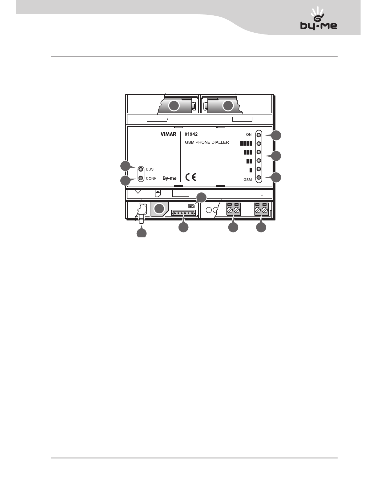
Front view
1-2. Battery compartments (removing the cover).
3. Green LED ON: external power supply present.
4. Red LEDs: display of the GSM module operating status/display of the GSM signal strength.
5. Push-button: turn on GSM signal strength display.
6. Power supply terminals 12-24 Vac, 12-30 Vdc.
Power supply input screw terminals (not polarized).
7. Bus input terminals.
Screw terminals for bus connection (polarized).
8. Jumper: reset initial parameters (removing the cover).
9. Programming connector.
Press-on connector for programming interface (removing the cover).
10. Housing for SIM CARD (not supplied).
Sliding in the SIM card (removing the cover).
11. SMB connector: connection of external GSM antenna.
Male press-on terminal.
12. Push-button: BUS interface configuration.
13. Green/red LED: display of the BUS interface operating statuses.
4. Front view
AAA NiMH 1,2 V AAA NiMH 1,2 V
492.1942A0 0A
BUS
+ -
12-30 V
12-24 V
PROG
492.1942A0 0A
1 2
10
9
11
8
7 6
12
13
3
3
5
Page 6

4
LED and push-button functions
AAA NiMH 1,2 V AAA NiMH 1,2 V
ON
GSM
BUS
+ -
12-30 V
12-24 V
BUS
PROG
CONF
LED
LED Colour Function
ON
green
Indicates there is an external power supply and that the GSM-BUS communicator is working.
red
The LED “ ” displays the operating status of the GSM module.
After pressing the GSM push-button they display the GSM signal strength.
BUS
Two-colour:
red/green
Displays the operating status of the BUS interface.
PUSH-BUTTONS
Button Function
GSM
It turns on the GSM signal strength display for a few seconds
BUS
It is used in the BUS interface configuration in the By-me system
5. LED and push-button functions
At the front of the GSM-BUS communicator there are two push-buttons and six LEDs with the functions
described below.
Page 7
5
ON
GSM
BUS
BUS
+ -
12-30 V
12-24 V
492.1942A0 0A
PROG
CONF
Preliminary operations
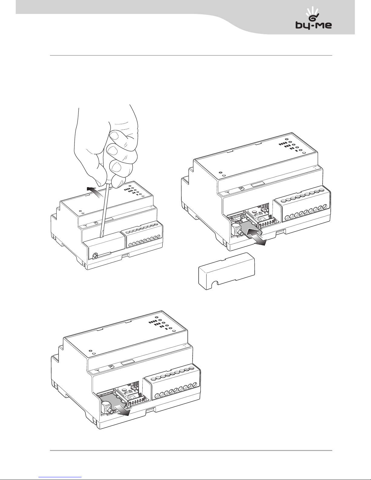
6. Preliminary operations
6.1 Inserting and removing the SIMcard
6.1.2 SIMcard insertion
ON
GSM
CONF
BUS
BUS
+ -
12-30 V
12-24 V
PROG
492.1942A0 0A
ON
GSM
BUS
+ -
12-30 V
12-24 V
PROG
BUS
CONF
6.1.3 SIMcard removal
6.1.1 Removing the cover
Page 8
6
Preliminary operations
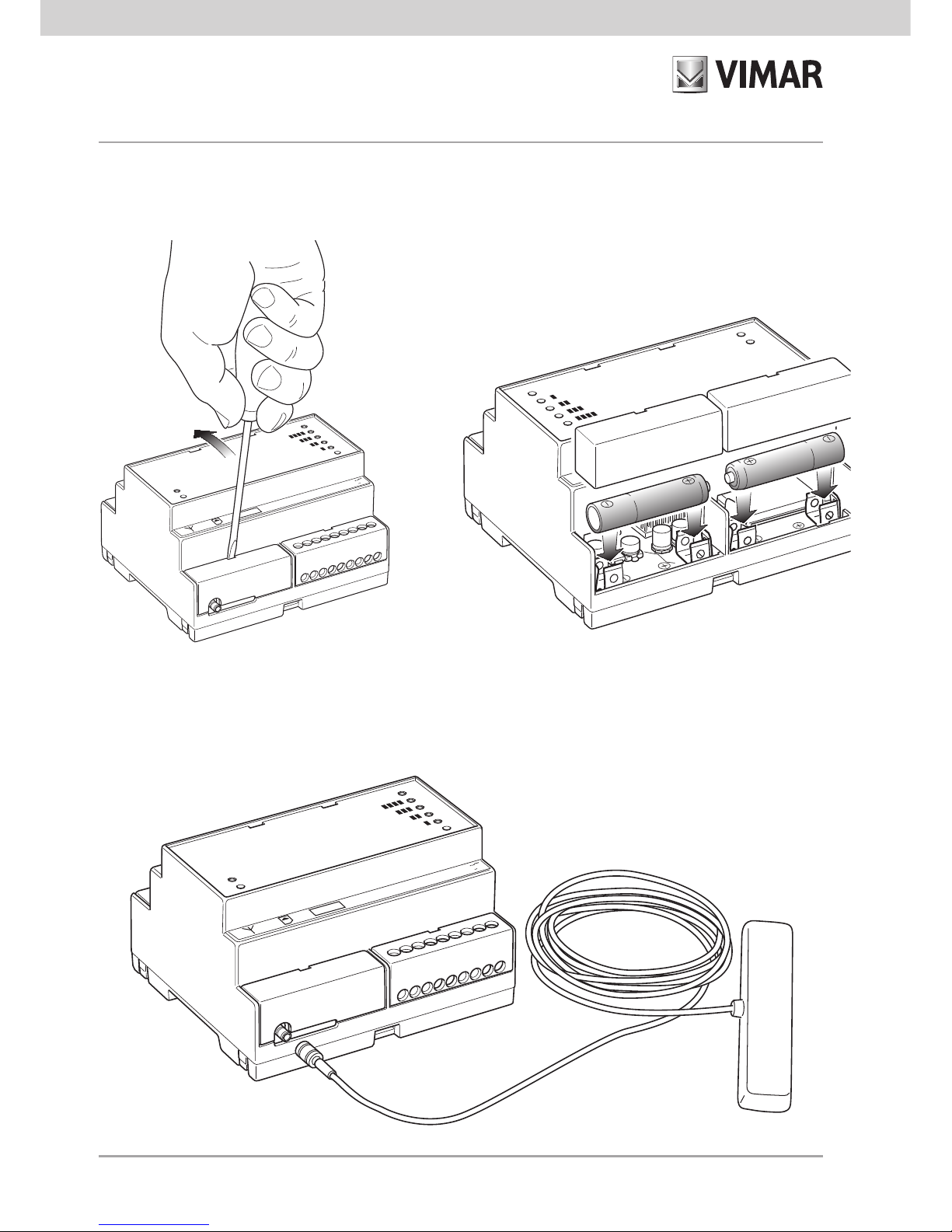
6.2 Inserting the batteries
6.2.1 Removing the terminal covers
6.2.2 Housing the rechargeable batteries
ON
GSM
CONF
BUS
BUS
+ -
12-30 V
12-24 V
PROG
492.1942A0 0A
BUS
AAA NiMH 1,2 V
AAA NiMH 1,2 V
492.1942A0 0A
ON
GSM
CONF
ON
GSM
BUS
BUS
+ -
12-30 V
12-24 V
PROG
CONF
6.3 Connecting the antenna
Page 9
7
Installation
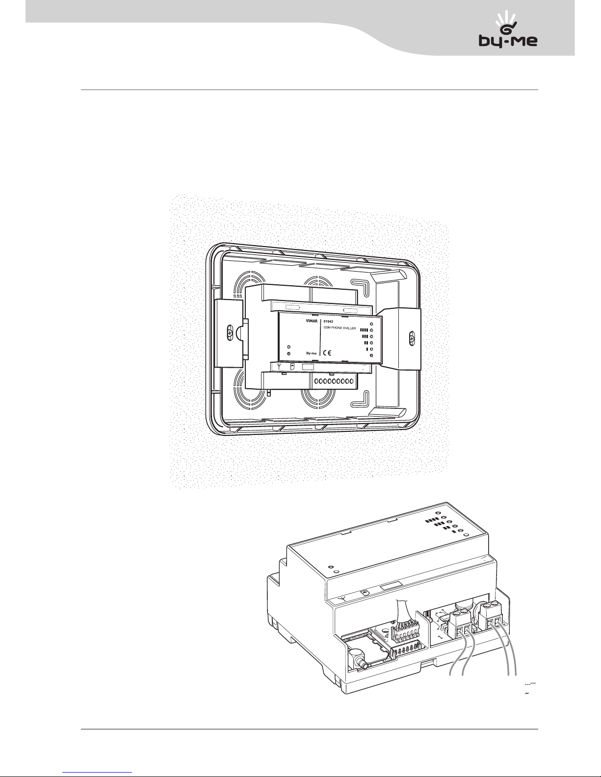
7. Installation
The GSM-BUS Communicator must be installed in a consumer unit with EN50022 rail.
The antenna must also be secured inside the consumer unit.
The consumer unit must be installed in a zone with a sufficiently strong GSM signal.
The cable of the GSM antenna enables installing the antenna even outside the consumer unit if it is not possible
to obtain a strong enough signal with the antenna fitted inside the consumer unit.
ON
GSM
BUS
CONF
BUS
+ -
12-30 V
12-24 V
PROG
492.1942A0 0A
AAA NiMH 1,2 V
AAA NiMH 1,2 V
492.1942A0 0A
7.1 Connections
ON
GSM
BUS
BUS
+ -
12-30 V
12-24 V
492.1942A0 0A
PROG
BUS
+
–
12-30 V
12-24 V
CONF
Warning!
Pay attention to the polarity where highlighted.
Page 10
8
Configuration
8. Configuration
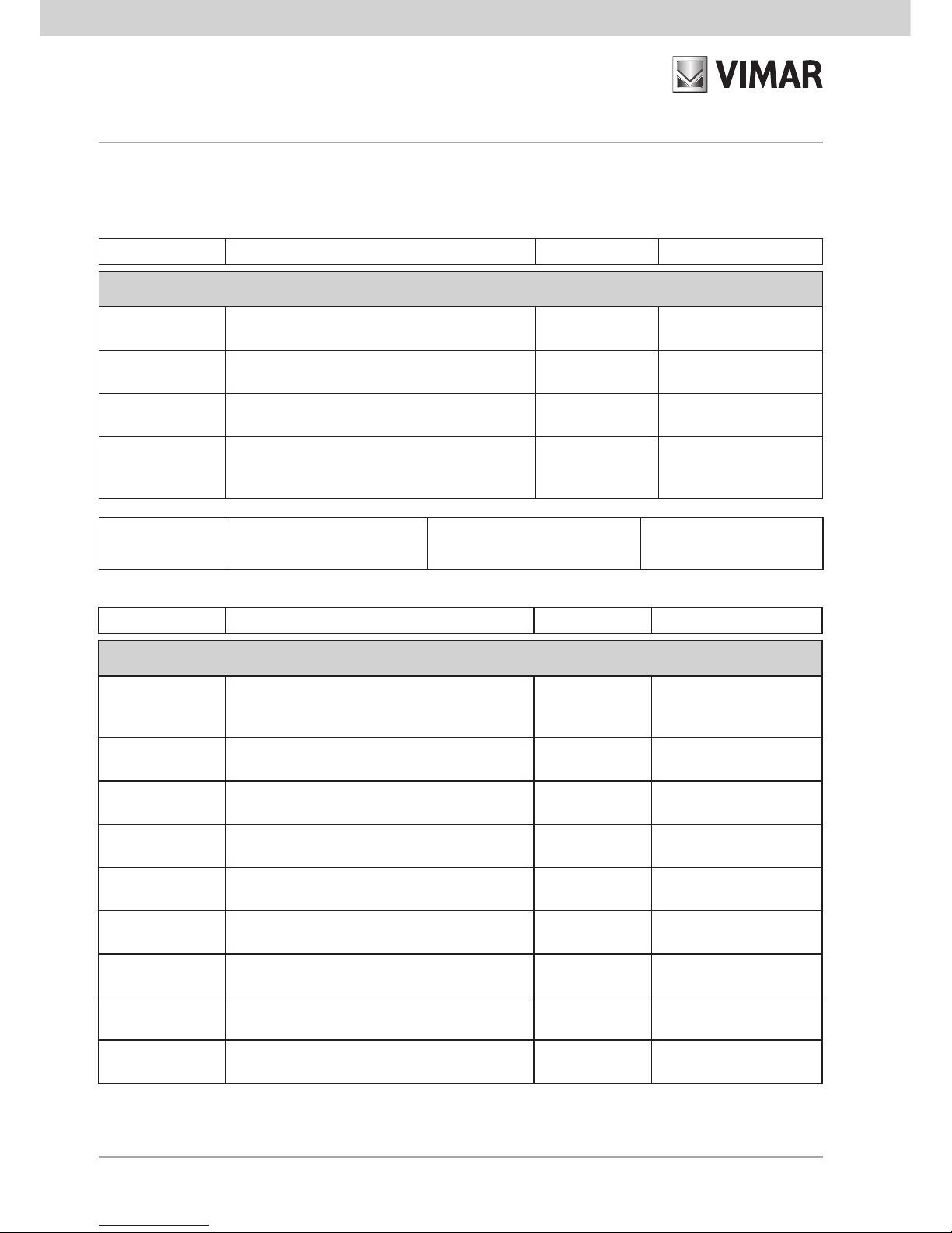
8.1 Predefined values
Parameter Description Predefined value Permissible values
General settings
User Code
Used to access the GSM-BUS Communicator
functions.
1234
min 4 digits max 10
digits
Phone number
table
Phone numbers to save for the associations with
the voice messages and SMS text messages.
Empty
max 8 phone numbers
of 30 digits each
Redirect noncontrolling SMS
Send non-system SMS texts to a set phone
number.
Disabled
max 1 phone number
can be associated
Send alarms
Associates the voice and SMS text alarm
messages to the phone numbers where they are
to be sent.
No number Max 8 numbers
Parameter Description Predefined value Permissible values
Editable voice message settings
Address
Voice message to “tag onto” an alarm message
to add information on the user or on the location
of the dwelling.
<empty>
Max total length of messages: approximately 29s
“Label”
Technical Alarm 1
Voice message for an additional description of
technical alarm number 1.
<empty>
Max total length of messages: approximately 29s
“Label”
Technical Alarm 2
Voice message for an additional description of
technical alarm number 2.
<empty>
Max total length of messages: approximately 29s
“Label”
Technical Alarm 3
Voice message for an additional description of
technical alarm number 3.
<empty>
Max total length of messages: approximately 29s
“Label”
Technical Alarm 4
Voice message for an additional description of
technical alarm number 4.
<empty>
Max total length of messages: approximately 29s
“Label”
Technical Alarm 5
Voice message for an additional description of
technical alarm number 5.
<empty>
Max total length of messages: approximately 29s
“Label”
Technical Alarm 6
Voice message for an additional description of
technical alarm number 6.
<empty>
Max total length of messages: approximately 29s
“Label”
Technical Alarm 7
Voice message for an additional description of
technical alarm number 7.
<empty>
Max total length of messages: approximately 29s
“Label”
Technical Alarm 8
Voice message for an additional description of
technical alarm number 8.
<empty>
Max total length of messages: approximately 29s
SMS language
Language used for the buttons and SMS commands
Language used for the prerecorded voice messages
IT, EN, DE, FR, ES, EL
Note: The max total length of voice messages includes the pre-recorded voice messages too.
Page 11
9
Configuration
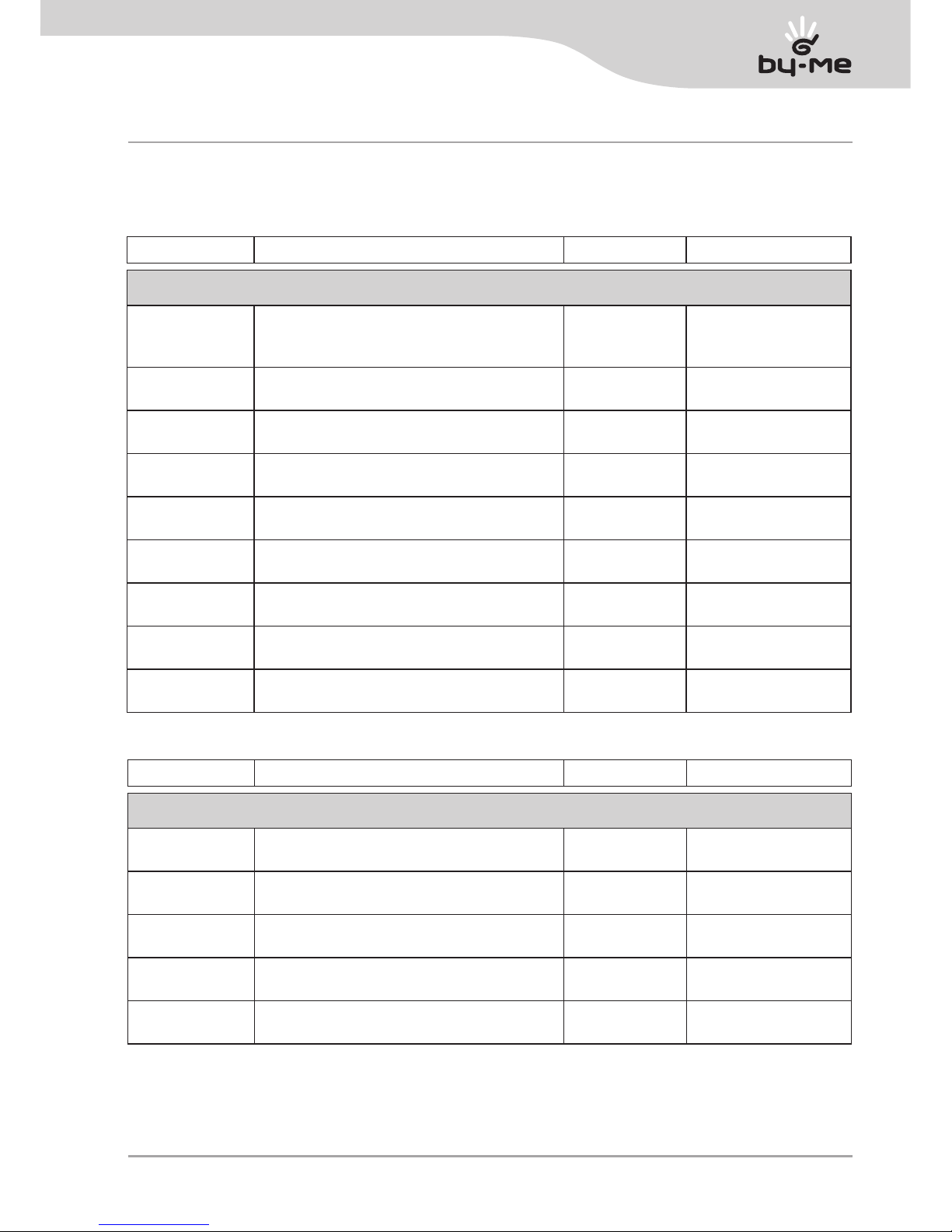
Parameter Description Predefined value Permissible values
Editable SMS text message settings
Address
Text that can be added in an SMS alarm message to provide information on the user or on the
location of the dwelling.
<empty>
Maximum length: 80
characters
“Label”
Technical Alarm 1
Text of additional description of technical alarm
number 1.
<empty>
Maximum length: 10
characters
“Label”
Technical Alarm 2
Text of additional description of technical alarm
number 2.
<empty>
Maximum length: 10
characters
“Label”
Technical Alarm 3
Text of additional description of technical alarm
number 3.
<empty>
Maximum length: 10
characters
“Label”
Technical Alarm 4
Text of additional description of technical alarm
number 4.
<empty>
Maximum length: 10
characters
“Label”
Technical Alarm 5
Text of additional description of technical alarm
number 5.
<empty>
Maximum length: 10
characters
“Label”
Technical Alarm 6
Text of additional description of technical alarm
number 6.
<empty>
Maximum length: 10
characters
“Label”
Technical Alarm 7
Text of additional description of technical alarm
number 7.
<empty>
Maximum length: 10
characters
“Label”
Technical Alarm 8
Text of additional description of technical alarm
number 8.
<empty>
Maximum length: 10
characters
Parameter Description Predefined value Permissible values
By-me system device settings
System
configuration data
Control panel address, control panel information. <empty>
<see system configuration chapters>
Thermostat
configuration data
Control panel address, temperature zone no.,
control panel information.
<empty>
<see thermostat configuration chapters>
Group
configuration data
Control panel address, group actuator data,
group no.
<empty>
<see group configuration chapters>
Scenario
configuration data
Control panel address, scenario no. <empty>
<see scenario configuration chapters>
Technical alarm
configuration data
Contact interface address, information, control
panel.
<empty>
<see alarm configuration
chapters>
Note.
If configuration parameters are set with values that are not permissible, the GSM-BUS communicator will automatically assign the nearest permissible value to the setting.
Page 12
10
Configuration
8.2 Start-up procedure
1. IMPORTANT: Make sure that the initial data reset “jumper” is not inserted. Otherwise, the previous
configuration data would be lost and the initial data restored.
2. Power up the GSM-BUS communicator: the “ON” LED blinks to indicate the phase of initializing the GSMBUS communicator.
3. After the initialization phase ends, the ON LED stops blinking and lights up steady to signal that the start-up
phase has been successful. After the start-up phase, the “ON” LED signals there is mains voltage.
4. Approximately 20 s after powering up, the GSM-BUS communicator activates the phone module start-up
procedure: the
“ ”
LED starts blinking quickly.
5. If the
“ ”
LED starts blinking slowly, the phone module start-up procedure and its subsequent registering on
the GSM network have concluded successfully.
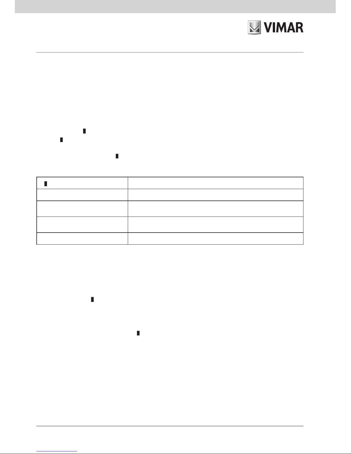
The following table gives the
“ ”
LED signals according to the GSM module status.
8.3 GSM signal detection:
1. Check the start-up procedure has concluded correctly and the GSM module has been registered on the
GSM network: the
“ ”
LED blinks slowly.
2. Press the “GSM” button
3. The yellow LEDs will show the strength of the GSM signal, whose value is indicated by the “bars” corresponding to the LEDs on.
Installation is possible even with only the
“ ”
LED on (minimum level).
Installation is not possible when there is no GSM signal. In this case, after trying to change the position of the
antenna without any success, it is necessary to find a zone covered by the GSM signal where the GSM-BUS
communicator can be positioned.
“ ” LED status
GSM module status
Permanently off GSM module off
Fast blink
(period 1 s, ON time 0.5 s)
Searching for GSM network / GSM module not registered on GSM
network / GSM module in the phase of switching off
Slow blink
(period 3 s, ON time 0.3 s)
GSM module on, registered on the GSM network and working
properly
Permanently on GSM module with an active call
Note: The start-up procedure is repeated after each time the GSM-BUS communicator is powered up.
Page 13
11
Configuration
8.4 Initial data reset procedure
Used to restore the initial settings of the GSM-BUS Communicator.
To activate the procedure, take the following steps:
1. Start with the GSM-BUS communicator off (Communicator not powered and without batteries or with flat
batteries).
2. Insert the “jumper” highlighted with number 8 in the “front view”.
3. Power up the GSM-BUS communicator: the “ON” LED blinks to indicate the phase of initializing the GSMBUS communicator.
4. After the initialization phase, the initial data reset procedure is activated: the operation is highlighted by the
“
” LED blinking.
5. After the initial data reset procedure, the “
” LED stays off and the communicator start-up procedure is
restarted: from point 3. of the “Start-Up Procedure” chapter.
IMPORTANT: After the initial data reset procedure, remove the jumper for initial data reset from the
relevant contacts. If the jumper stays inserted in the contacts, each time the communicator is restarted, the initial data would be restored, losing the data of any configurations made.
8.5 Using SMS
It is possible to send SMS text messages for configuration, control and requests to the GSM-BUS
Communicator as follows:
<code>.<sms_content>/<sms_content>/...
where:
• <code> is the user code;
• is the information separator
• <sms_content> depends on the function you want to actuate
• / is the separator for configurations, commands, multiple requests
If the GSM-BUS Communicator receives SMS messages with the right user code but with errors in the content,
it will send an error SMS message containing the incorrect text and an indication of the command (or commands) with the incorrect content.
Example. Suppose you want to send an SMS message with 4 commands of which the first and last are incorrect. The GSM-BUS Communicator will send an error SMS message with the following form:
GSM-BUS 1/1
<SMS received from the GSM Communicator containing the 4 commands>
Error on command/s:
1 4
In the case of SMS messages with multiple commands requiring an answer, the GSM-BUS Communicator is
able to send at most 8 SMS messages in response.
Page 14

12
General configuration
9. General configuration
9.1 Language configuration
The GSM-BUS communicator interacts with the user via SMS messages and voice messages, available in the
following languages:
Italian, English, German, French, Spanish, Greek.
It is possible to change the language used by the GSM-BUS communicator.
9.1.1 Setting the language for voice messages
The choice of language used for the voice messages must be made using the PC software EasyTool through
which the voice messages in the chosen language are downloaded to the GSM-BUS communicator.
Note: Refer to the EasyTool instructions manual.
9.1.2 Setting the language for SMS messages
The choice of language used for the SMS messages can be made either via SMS or by using the PC software
EasyTool.
To change language, send the following SMS. The procedure does not require any SMS message for confirmation from the communicator.
<user code>.L.<language code>
where <language code> is the code of the language to set, using the following values:
IT = Italian
EN = English
DE = German
FR = French
ES = Spanish
EL = Greek
Example.
If the set user code is the default 1234 and you want to set English for the SMS messages, send the following
SMS:
1234.L.EN
9.1.3 Displaying the current language
It is possible to read the current language used by the communicator, either via SMS or with the PC application
EasyTool.
To display the language code via SMS send the following SMS message:
<user code>.?L
to which the communicator will respond with the SMS message:
GSM-BUS 1/1
SMS L:<language code>
VOC L:<language code>
Page 15

13
General configuration
where <language code> has the meaning stated above, SMS L is the language used for the SMS messages, VOC L is the language used for the voice alarm messages.
9.2 User code configuration
The GSM-BUS Communicator enables setting a numerical password (user code) composed of from a minimum
of 4 digits to a maximum of 10 digits providing access to its functions:
• Send an SMS message in the form of
<user code>.COD.<new code>
- If the sent code has more than 10 digits, the GSM-BUS Communicator will send the following SMS error
message:
GSM-BUS 1/1
Error:
Code too long
- If the sent code has less than 4 digits, the GSM-BUS Communicator will send the following SMS error message:
GSM-BUS 1/1
Error:
Code too short
- If the sent code has non-numerical characters, the GSM-BUS Communicator will send the following SMS
error message:
GSM-BUS 1/1
Error:
Inadmissible characters
- If the sent code respects the required form, the GSM-BUS Communicator will send the following SMS confirmation message:
GSM-BUS 1/1
Code entered:
<code>
Example. If the set user code is the default 1234 and you want to change it with the new code 6767, the
SMS message to send must be
1234.COD.6767
The GSM-BUS Communicator will send the following SMS confirmation message:
GSM-BUS 1/1
Code entered:
6767
Page 16

14
General configuration
9.3 Phone number configuration
The GSM-BUS Communicator is able to manage up to at most 8 phone numbers, which can be stored in the
same number of memory locations, to make voice calls and/or send SMS messages. The functions for managing the phone numbers are given here:
nRead: to check the phone numbers saved in the 8 positions.
• Send an SMS message in the form of
<user code>.?NUM
The GSM-BUS Communicator will send a response SMS message with the list of all the saved phone numbers in the following form:
GSM-BUS 1/1
1:<phone number 1>
2:<phone number 2>
3:<phone number 3>
4:<phone number 4>
5:<phone number 5>
6:<phone number 6>
7:<phone number 7>
8:<phone number 8>
Example. If the set user code is the default 1234 and the numbers saved in the GSM-BUS Communicator are
333778899 (position 1) and 333445566 (position 5), the SMS message to send must be
1234.?NUM
whereas the response SMS message sent by the GSM-BUS Communicator will be:
GSM-BUS 1/1
1:333778899
2:
3:
4:
5:333445566
6:
7:
8:
nAdd: used to save a phone number in one of the 8 positions. The procedure does not require any SMS mes-
sage for confirmation from the GSM-BUS communicator.
• Send an SMS message in the form of
<user code>.NUM<n>.<phone number>
where <n> is the memory location (from 1 to 8) and <phone number> s the number to save.
Page 17

15
General configuration
Example. If the set user code is the default 1234 and you want to set the number 333778899 in position 1,
send the following SMS:
1234.NUM1.333778899
nDelete: used to delete a phone number saved in one of the 8 positions. The procedure does not require any
SMS message for confirmation from the GSM-BUS communicator.
• Send an SMS message in the form of
<user code>.NUM<n>.0 (zero)
where <n> is the memory location (from 1 to 8)
Example. If the set user code is the default 1234 and you want to delete the number in position 1, send the
following SMS:
1234.NUM1.0
9.4 Redirect phone number configuration
It is possible to configure the GSM-BUS Communicator so as to redirect any non-system SMS messages it
receives (for example, information sent by the phone carrier) to a specified phone number.
• Send an SMS message in the form of:
<user code>.RED.NUM<n>
where <n> is the memory location storing the phone number for redirecting (from 1 to 8). The GSM-BUS
Communicator will send an SMS reply message with the following format:
GSM-BUS 1/1
SMS Redirect to number of index
Example. If the set user code is the default 1234 and you want to redirect all the non-system SMS messages
coming to the GSM-BUS Communicator to the phone number of position 1, send the following SMS:
1234.RED.NUM1
The response SMS message sent by the GSM Communicator will be:
GSM-BUS 1/1
SMS Redirect to number of index
To turn off this function, send the following SMS:
<user code>.RED.NUM.0 (zero)
Page 18

16
General configuration
The response SMS message sent by the GSM-BUS Communicator will be:
GSM-BUS 1/1
SMS Redirect OFF
To read the settings, send an SMS message in the form of:
<user code>.?RED
If the function is on and associated with the phone number saved in position n, the GSM-BUS Communicator
will send the following SMS confirmation message: :
GSM-BUS 1/1
SMS Redirect to number of index <n>
Otherwise, the GSM-BUS Communicator will send the following SMS:
GSM-BUS 1/1
SMS Redirect OFF
9.5 Configuring voice alarm messages
The GSM-BUS Communicator is able to make voice alarm calls, playing back voice messages, that the user
can customize.
Voice messages can be customized by using a personal computer equipped with the software application
called EasyTool which is described in the relevant instructions manual.
The alarm conditions that generate sending voice calls, which will be described below, are the following:
• Intrusion alarm
• Tamper alarm: the communicator, besides the conditions of “Tamper Alarm” generated by the intrusion
detection alarm system, is able to generate a “Tamper Alarm” event independently when, after detecting a
SAI VIMAR system, it no longer detects it for over a minute.
• Technical Alarm: it is possible to send 8 separate technical alarms, managing the technical alarm events
generated by contact interfaces belonging to VIMAR home automation or intrusion detection alarm systems.
Note: These alarm events are generated by the home automation or intrusion detection alarm systems and are
described in the relevant instruction manuals.
The voice alarm messages are composed, as described below, by linking two or three voice messages
(depending on the type of voice alarm message): the first one is predefined and the others are optional and can
be modified by the user. In brief, a voice message is composed of the following part:
Page 19
17
General configuration
Specifically, for the types of alarm managed:
1. Intrusion alarm.
The Intrusion voice alarm message is formed in this way
“Intrusion Alarm”
+
Msg. Address (option)
2. Tamper alarm.
The Tamper voice alarm message is formed in this way
“Tamper Alarm”
+
Msg. Address (option)
3. Technical alarm.
The Technical voice alarm messages are formed in this way
“Technical Alarm”
+
description of alarm
type (option)
+
Msg. Address (option)
The voice alarm messages (VOC) managed by the GSM-BUS communicator are divided into two groups, which
are associated with the same number of groups of call phone numbers, composed of at most 8 phone numbers
of a maximum length of 30 digits.
This division enables sending the two “classes” of alarm messages to two groups of users, separating “safety”
alarm messages (intrusion and tamper alarms) from “technical” ones.
Group name Description Alarms belonging to the group
“VOCAI” GROUP
Group of voice alarms in the category of
INTRUSION ALARMS
Intrusion alarm
Tamper alarm
“VOCAT” GROUP
Group of voice alarms in the category of
TECHNICAL ALARMS
Technical alarm 1
...
Technical alarm 8
Sending an alarm message (together with all those in the same group) is activated by associating the group with
at least one phone number on the list of phone numbers.
Sending alarm messages can therefore be enabled or disabled according to the group to which they belong.
For each group of alarm messages there are the following functions available, via SMS or PC.
Note: For settings via the specific software on a PC, please refer to the relevant instructions manual.
ALARM TYPE
DESCRIPTION OF ALARM TYPE
(FOR TECHNICAL ALARMS ONLY)
ADDRESS
• predened
• depending on the type of
alarm event
• cannot be changed by the
user
• option
• can be changed by the user
(via PC)
• enables identifying the type
of technical alarm (e.g., gas,
smoke, water...)
• option
• can be changed by the user (via PC)
• used to add information on the user
or on the location of the dwelling to
the voice alarm message
Page 20

18
General configuration
nAssociation with phone numbers: used to associate the group of voice messages with up to 8 phone
numbers, configured as described in chapter 9.3. The procedure does not require any SMS message for
confirmation from the communicator.
• For the INTRUSION ALARM group, send the following SMS:
<user code>.VOCAI.NUM.<n1...n8>
where <n1...n8> is the list of indices of the phone numbers for associating the group of voice messages.
Example.
If the set user code is the default 1234 and you want to associate the group of voice messages of the intrusion alarms with the phone numbers 1, 2 and 5, send the following SMS:
1234.VOCAI.NUM.125
• For the TECHNICAL ALARMS group, send the following SMS:
<user code>.VOCAT.NUM.<n1...n8>
where <n1...n8> is the list of indices of the phone numbers for associating the group of voice messages.
Example.
If the set user code is the default 1234 and you want to associate the group of voice messages of the technical alarms with the phone numbers 1, 2 and 5, send the following SMS:
1234.VOCAT.NUM.125
nDeleting association with phone numbers: used to delete the association between a group of voice mes-
sages and all the phone numbers. The procedure does not require any SMS message for confirmation from
the communicator.
• For the INTRUSION ALARM group, send the following SMS:
<user code>.VOCAI.NUM.0
(zero)
Example.
If the set user code is the default 1234 and you want to delete the association of the group of voice messages of the intrusion alarms from all the phone numbers, send the following SMS:
1234.VOCAI.NUM.0
• For the TECHNICAL ALARMS group, send the following SMS:
<user code>.VOCAT.NUM.0
(zero)
Example.
If the set user code is the default 1234 and you want to delete the association of the group of voice messages of the technical alarms from all the phone numbers, send the following SMS:
1234.VOCAT.NUM.0
Page 21

19
General configuration
nReading association with phone numbers: used to know which phone numbers are associated with the
groups of voice messages. Send an SMS message in the form of:
<user code>.?VOC
The GSM-BUS Communicator will send a response SMS message with the list of all the associations
between the phone numbers and the groups of voice alarm messages:
GSM-BUS 1/1
VOCAI: <list of associated phone number indices>
VOCAT: <list of associated phone number indices>
Example.
If the set user code is the default 1234, the group of voice messages of the intrusion alarms has been associated with the phone numbers 1, 2 and 3, and the group of voice messages of the technical alarms has been
associated with the phone numbers 1 and 4, upon sending the SMS message:
1234.?VOC
The GSM-BUS Communicator will send the following SMS reply message:
GSM-BUS 1/1
VOCAI: 1 2 3
VOCAT: 1 4
9.6 Configuring SMS alarm messages
The GSM-BUS GSM-BUS Communicator is able to send SMS text messages, with the possibility for the user to
customize their content.
SMS messages can be customized by using sending a configuration SMS or using a personal computer
equipped with the software application called EasyTool, as described in the relevant instructions manual.
The alarm conditions that generate sending SMS alarm messages, which will be described below, are the following:
1. Intrusion alarm
2. Tamper alarm: the communicator, besides the conditions of “Tamper Alarm” generated by the intrusion
detection alarm system, is able to generate a “Tamper Alarm” event independently when, after detecting a
SAI VIMAR system, it no longer detects it for over a minute.
3. Technical Alarm: it is possible to send 8 separate technical alarms, managing the technical alarm events
generated by contact interfaces belonging to VIMAR home automation or intrusion detection alarm systems.
4. No Mains power
5. Restore mains power
Note: The Intrusion, Tamper and Technical alarm events are generated by the home automation or intrusion
detection alarm systems and are described in the relevant instruction manuals.
Page 22

20
General configuration
The SMS alarm messages are composed, as described below, by linking two or three text messages (depending on the type of voice alarm message): the first one is predefined and the others are optional and can be
modified by the user. In brief, an SMS message is composed of the following parts:
Specifically, for the types of alarm managed:
1. Intrusion alarm
The Intrusion SMS alarm message is formed in this way
“Intrusion Alarm”
+
Msg. Address (option)
2. Tamper alarm
The Tamper SMS alarm message is formed in this way
“Tamper Alarm”
+
Msg. Address (option)
3. Technical alarm
The Technical SMS alarm messages are formed in this way
“Technical Alarm”
+
description of alarm
type (option)
+
Msg. Address (option)
4. No Mains power/Restore mains power Alarm
The No Mains Voltage SMS message is formed in this way
“No mains power!”
The Reset Mains Voltage SMS message is formed in this way
“Restore mains power!”
Note: The GSM-BUS communicator generates a No Mains power event when the required electrical power is
not supplied to the relevant terminals.
The SMS alarm messages managed by the GSM-BUS communicator are divided into three groups, which are
associated with the same number of groups of phone numbers, composed of at most 8 phone numbers of a
maximum length of 30 digits.
ALARM TYPE
DESCRIPTION OF ALARM TYPE
(FOR TECHNICAL ALARMS ONLY)
ADDRESS
• predened
• depending on the type of
alarm event
• cannot be changed by the
user
• option
• can be changed by the user (via
SMS or PC)
• enables identifying the type
of technical alarm (e.g., gas,
smoke, water...)
• opzionale
• can be changed by the user (via
SMS or PC)
• used to add information on the user
or on the location of the dwelling to
the SMS alarm message
Page 23

21
General configuration
This division enables sending the three “classes” of alarm messages to three groups of users, separating “safety” alarm messages (intrusion and tamper alarms) from “technical” ones and from “power supply” ones.
Group name Description Alarms belonging to the group
“SMSAI” GROUP
Group of SMS alarms in the category of
INTRUSION ALARMS
Intrusion alarm
Tamper alarm
“SMSAT” GROUP”
Group of SMS alarms in the category of
TECHNICAL ALARMS
Technical alarm 1
...
Technical alarm 8
“SMSAR” GROUP
Group of SMS alarms in the category of
POWER SUPPLY ALARMS
No/Restore mains power alarm
SAI Backup Alarm on/off
Sending an alarm message (together with all those in the same group) is activated by associating the group with
at least one phone number on the list of phone numbers.
Sending alarm messages can therefore be enabled or disabled according to the group to which they belong.
For each group of alarm messages there are the following functions available, via SMS or PC.
Note: For settings via the specific software on a PC, please refer to the relevant instructions manual.
nAssociation with phone numbers: used to associate the group of SMS messages with up to 8 phone num-
bers, configured as described in chapter 9.3. The procedure does not require any SMS message for confirmation from the communicator.
• For the INTRUSION ALARM group, send the following SMS:
<user code>.SMSAI.NUM.<n1...n8>
where <n1...n8> is the list of indices of the phone numbers for associating the group of SMS messages.
Example. If the set user code is the default 1234 and you want to associate the group of SMS messages of
the intrusion alarms with the phone numbers 1, 2 and 5, send the following SMS:
1234.SMSAI.NUM.125
• For the TECHNICAL ALARMS group, send the following SMS:
<user code>.SMSAT.NUM.<n1...n8>
where <n1...n8> is the list of indices of the phone numbers for associating the group of SMS messages.
Example. If the set user code is the default 1234 and you want to associate the group of SMS messages of
the technical alarms with the phone numbers 1, 2 and 5, send the following SMS:
1234.SMSAT.NUM.125
• For the POWER SUPPLY ALARMS group, send the following SMS:
<user code>.SMSAR.NUM.<n1...n8>
Page 24

22
General configuration
where <n1...n8> is the list of indices of the phone numbers for associating the group of SMS messages.
Example.
If the set user code is the default 1234 and you want to associate the group of SMS messages of the power
supply alarms with the phone numbers 1, 2 and 5, send the following SMS:
1234.SMSAR.NUM.125
nDeleting association with phone numbers: used to delete the association between a group of SMS mes-
sages and all the phone numbers. The procedure does not require any SMS message for confirmation from
the communicator.
• For the INTRUSION ALARM group, send the following SMS:
<user code>.SMSAI.NUM.0 (zero)
Example.
If the set user code is the default 1234 and you want to delete the association of the group of SMS messages of the intrusion alarms from all the phone numbers, send the following SMS:
1234.SMSAI.NUM.0
• For the TECHNICAL ALARMS group, send the following SMS:
<user code>.SMSAT.NUM.0 (zero)
Example.
If the set user code is the default 1234 and you want to delete the association of the group of SMS messages of the technical alarms from all the phone numbers, send the following SMS:
1234.SMSAT.NUM.0
• For the POWER SUPPLY ALARMS group, send the following SMS:
<user code>.SMSAR.NUM.0 (zero)
Example. If the set user code is the default 1234 and you want to delete the association of the group of SMS
messages of the power supply alarms from all the phone numbers, send the following SMS:
1234.SMSAR.NUM.0
nReading association with phone numbers: used to know which phone numbers are associated with the
groups of SMS messages. Send an SMS message in the form of:
<user code>.?SMS
The GSM-BUS Communicator will send a response SMS message with the list of all the associations
between the phone numbers and the groups of SMS alarm messages:
GSM-BUS 1/1
SMSAI: <list of associated phone number indices>
SMSAT: <list of associated phone number indices>
SMSAR: <list of associated phone number indices>
Page 25

23
General configuration
Example.
If the set user code is the default 1234, the group of SMS messages of the intrusion alarms has been associated with the phone numbers 1, 2 and 3, and the group of SMS messages of the technical alarms has been
associated with the phone numbers 1 and 4, and the group of SMS messages of the power supply alarms
has been associated with the phone number 1, upon sending the SMS message:
1234.?SMS
The GSM-BUS Communicator will send the following SMS reply message:
GSM-BUS 1/1
SMSAI: 1 2 3
SMSAT: 1 4
SMSAR: 1
nSMS text configuration: used to customize the text of the editable parts of the SMS alarm messages. The
procedure does not require any SMS message for confirmation from the communicator.
• For the ADDRESS text, send the following SMS:
<user code>.ADDR.<text>
Example.
If the set user code is the default 1234 and you want to add information on the user and address to the alarm
messages with the text “Mario Rossi via Verdi 567 VICENZA”, send the following SMS:
1234.ADDR.Mario Rossi via Verdi 567 VICENZA
• For a description of the TECHNICAL ALARMS, send the following SMS:
<user code>.AT<n>.STR.<text>
where <n> (from 1 to 8) is the index of the technical alarm for which you want to set an additional description.
Example.
If the set user code is the default 1234 and you want to add the description “GAS” to the technical alarm
AT1, send the following SMS:
1234.AT1.STR.GAS
nDeleting SMS texts: used to delete the text of the editable parts of the SMS alarm messages. The proce-
dure does not require any SMS message for confirmation from the communicator.
<user code>.?SMS
• For the ADDRESS text, send the following SMS:
<user code>.ADDR.0
(zero)
Example.
If the set user code is the default 1234 and you want to delete the ADDRESS text, send the following SMS:
1234.ADDR.0
Page 26

24
General configuration
• For a description of the TECHNICAL ALARMS, send the following SMS:
<user code>.AT<n>.STR.0
(zero)
where <n> (from 1 to 8) is the index of the technical alarm for which you want to delete the text of the additional description.
Example.
If the set user code is the default 1234 and you want to delete the additional description of the technical
alarm AT1, send the following SMS:
1234.AT1.STR.0
nReading SMS texts: used to read the text of the editable parts of the SMS alarm messages.
• For the ADDRESS text, send the following SMS:
<user code>.?ADDR
The GSM-BUS Communicator will send a response SMS message with the ADDRESS text:
GSM-BUS 1/1
ADDR:
<ADDRESS text>
Example. If the set user code is the default 1234 and the ADDRESS text is “Mario Rossi via Verdi 567
VICENZA”, to the request message:
1234.?ADDR
The GSM-BUS Communicator will send the following SMS reply message:
GSM-BUS 1/1
ADDR:
Mario Rossi via Verdi 567 VICENZA
• For a description of the TECHNICAL ALARMS, send the following SMS:
<user code>.AT<n>.?STR
where <n> (from 1 to 8) is the index of the technical alarm for which you want to read the additional description.
The GSM-BUS Communicator will send a response SMS message with the ATn text:
GSM-BUS 1/1
At<n>:<ATn description text>
Example. If the set user code is the default 1234 and you want to read the additional description “GAS” of
the technical alarm AT1, upon sending the message:
1234.AT1.?STR
The GSM-BUS Communicator will send the following SMS reply message:
GSM-BUS 1/1
AT1:GAS
Page 27

25
Alarm warning - Configuration of the bus interface
10. Alarm warning
The GSM-BUS Communicator manages voice and SMS alarm messages that can be associated with up to 8
phone numbers.
The alarm warning procedure is the following:
• The procedure of SENDING -ALARM SMS: the communicator checks there are the phone numbers associ-
ated with the SMS message and then sends these numbers an SMS. If there are no associated phone numbers, the SMS message will not be sent.
• The procedure of SENDING VOICE MESSAGE: the communicator checks there are the phone numbers
associated with the voice message and starts up the following procedure:
1. It sends the message to the first phone number. If the user replies, the message is duplicated and the user
code is requested;
2. If the user enters the correct code, the procedure ends; the GSM Communicator ends the communication
and deletes the alarm status of the system on the GSM-BUS communicator;
3. If the user enters an incorrect code, it hangs up during the alarm warning or does not answer the call.
If there is a following phone number, the GSM-BUS Communicator waits 30 seconds and then restarts
the procedure for sending the voice message from the next phone number. If there is no following phone
number, the communicator waits 90 seconds and restarts from point 1.
4. After the third cycle of sending the voice message to all the associated phone numbers, the communicator
cancels the alarm status. If there are no associated phone numbers, the voice message will not be sent.
11. Configuration of the bus interface of the communicator and preliminary operations on the By-me control panels.
11.1 BUS interface configuration.
The bus interface of the 01942 communicator must be learned by the control panel using the specific menu.
From the point of view of the By-me control panel, the operation to perform is exactly the same one used for
learning the interface 01848 (refer to the control panel instructions manual). The push-button and the “BUS”
LED of the GSM-BUS communicator 01942 have the same functions as the push-button and LED of the
01848 interface.
11.2 Preliminary configurations for remote control of the intrusion detection alarm
system.
If the intrusion detection alarm system is governed by one of the control panels 20480 (SW version 4.0 or higher), 16930 (SW version 4.0 or higher), 14480 (SW version 4.0 or higher), 01950, 01951, 01952, 01956, 01958
or 01960 for the GSM-BUS communicator to be able to access the intrusion detection alarm system from a
remote location it is necessary to run the Phone Communicator configuration procedure from the specific menu
of the control panel (see instructions manual of the control panel.
Page 28

26
Enrolling devices
12. Enrolling By-me system devices
Note: Access to the configuration operations is possible approximately one minute after powering up the system.
12.0 Enrolling the control panels
This procedure is necessary to allow the communicator to access the control panel functions that you want to
control from a remote location. An association is created between the systems SYS1, SYS2,..., SYS8 that can
be managed by the phone communicator and the above-mentioned control panels installed in the system. It is
possible to govern up to 8 control panels that are identified in the phone communicator with SYS1 (System no.
1), SYS2 (System no. 2), and so on to SYS8 (System no. 8).
The device SYSn (SYS1, SYS2, .. SYS8) of the phone communicator must be associated with the address that
identifies the desired comfort control panel. This association can be made via SMS or via the EasyTool. The
above-mentioned address has the following format:
a . b . c
a Identifies the area
b Identifies the line
c Identifies the control panel
On the control panels 14510, 16950, 20510, the values can be displayed in the Diagnostics-Information menu.
On the control panels 01950, 01951, 01952, 01956, 01958, 01960, the area and line values can be displayed
in the Setup-Information menu, while the ID value is 170 (for a description of these values, refer to the instructions manual of the control panel).
• Send an SMS message in the form of
<user code>.SYS<n>.ID.<control panel address>
where <n> is the number identifying the system you want to associate with the control panel with the
address <control panel address>
<control panel address> must have the format xxyyzzz with:
xx
two digits (between 00 and 15) identifying the area
yy
two digits, between 00 and 15, identifying the line
zz
three digits, identifying the control panel
This command does not require an SMS confirmation message.
Example.
If the set user code is the default 1234 and you want to make an association between SYS1 and the control
panel with address 1.8.1, send the following SMS:
1234.SYS1.ID.0108001
Page 29

27
Enrolling devices
12.1 Reading the address and information of the control panel
This procedure is used to obtain information on the address, type of control panel, hardware version and software release concerning the control panels managed by the communicator. Reading the address and requesting information can be done either with an SMS text message or via the EasyTool.
• Reading address: send an SMS message in the form of
<user code>.?SYSID
The communicator will send an SMS with the data related to the association of the enrolled control panels:
GSM-BUS 1/1
SYS1: <control panel address>
SYS2: <control panel address>
...
Example.
If the set user code is the default 1234 and you want to read the associations of the control panels (with
SYS1 associated with the control panel of address 1.8.1 and SYS2 associated with the control panel of
address 1.3.1), send the following SMS:
1234.?SYSID
The communicator will send the following SMS:
GSM-BUS 1/1
SYS1: 1.8.1
SYS2: 1.3.1
• Reading control panel information: send an SMS message in the form of
<user code>.SYS<n>.INFO
where <n> is the number identifying the system whose information you want to read (address, type of control panel, hardware version and software release)
The communicator will send an SMS with the data related to the association:
GSM-BUS 1/1
SYS<n>: <control panel address>
type: <control panel type>
hw ver:<hw version>
sw ver:<sw version>
Note: The data <control panel type> takes the following values:
- 0, for control panels: 14510, 16950, 20510
- 1, for control panels: 01950, 01951, 01952, 01956, 01958 and 01960
Example. If the set user code is the default 1234 and you want to read the SYS1 system information, send
the following SMS:
1234.SYS1.INFO
Page 30

28
Enrolling devices
12.2 Deleting control panel enrolment
It is possible to delete an association created with the procedure described in paragraph 12.0 Enrolling the control panels, with an SMS message or via EasyTool.
• Send an SMS message in the form of
<user code>.SYS<n>.ID.0 (zero)
where <n> is the number identifying the system whose association with a control panel you want to delete.
This command does not require an SMS confirmation message.
Example.
If the set user code is the default 1234 and you want to delete the SYS1 system association, send the following SMS:
1234.SYS1.ID.0
(zero)
12.3 Enrolling the temperature zones of the control panels
This procedure is necessary to allow the GSM-BUS 01942 communicator to access the temperature zones of
the control panels.
The phone communicator 01942 is able to manage up to at most 40 temperature zones. During the enrolment
procedure an association is created between the “thermostat” devices (C1..C40) of the communicator and the
temperature zones of the control panels. The first 8 thermostats (C1..C8) of the communicator 01941 can be
managed from a remote location via SMS messages, with the possibility of associating a customized SMS label
(with at most 10 characters). The following thermostats, that is from C9 to C40, can be managed completely via
SMS and it is not possible to customize the related SMS labels (they can therefore be accessed from a remote
location using the predefined SMS labels: C9..C40). The modes of access to the 40 thermostats that the GSMBUS 01942 communicator can manage are summarized in the following table.
Thermostat
index
Predefined SMS
label
Customizable
SMS label
Can be activated
via SMS
1 C1 YES YES
2 C2 YES YES
. . . . . . . . . . . .
8 C8 YES YES
9 C9 NO YES
10 C10 NO YES
. . . . . . . . . . . .
40 C40 NO YES
Page 31

29
Enrolling devices
For a temperature zone to be able to be managed from a remote location via the GSM-BUS Communicator
01942, it is first necessary to enable remote access, using the specific menu of the control panel (refer to the
relevant instructions manual).
It is possible to perform the temperature zone enrolment procedure by following an automatic procedure or a
manual procedure.
12.3.1 Automatic enrolment of the control panel temperature zones.
This procedure makes a sequential association of the temperature zones that the specified control panel makes
accessible from a remote location.
The procedure involves the following operations:
1. The first available “thermostat” (C1,.., C40) of the communicator is associated with the first enabled temperature zone of the specified control panel.
2. The second available “thermostat” of the communicator is associated with the second enabled temperature zone of the control panel.
....and so on for all the temperature zones of the control panel or of the available “thermostats” in the communi-
cator.
Therefore, if 40 temperature zones have already been enrolled, another automatic enrolment command will have
no effect.
Example: If you want to enrol temperature zones 1, 2, 3, 4 of the control panel associated with the SYS1 system and the temperature zones 1, 2, 3, 4 of the comfort control panel associated with the SYS2 system using
the automatic procedure, if other temperature zones have not previously been enrolled, you will obtain the following association:
C1
Temperature zone 1 of the control panel 1 (SYS1)
C2
Temperature zone 2 of the control panel 1 (SYS1)
C3
Temperature zone 3 of the control panel 1 (SYS1)
C4
Temperature zone 4 of the control panel 1 (SYS1)
C5
Temperature zone 1 of the control panel 2 (SYS2)
C6
Temperature zone 2 of the control panel 2 (SYS2)
C7
Temperature zone 3 of the control panel 2 (SYS2)
C8
Temperature zone 4 of the control panel 2 (SYS2)
The procedure can be activated either with an SMS text message or via the EasyTool.
• Send an SMS message in the form of
<user code>.SYS<n>.AAC
where <n> is the number identifying the system associated with the control panel of the temperature zones
to enrol.
This command does not require an SMS confirmation message.
Page 32

30
Enrolling devices
Example.
If the set user code is the default 1234 and you want to enrol the temperature zones of the control panel
associated with the SYS1 system, send the following SMS:
1234.SYS1.AAC
Note.
Before automatically enrolling the temperature zones of a control panel it is necessary to have first enrolled
the control panel (see paragraph 12.1).
12.3.2 Manual enrolment of the control panel temperature zones
This procedure permits manually creating the association between a thermostat that can be controlled with
the phone communicator (C1,.., C40) and an active temperature zone of a control panel. It is also possible to
associate temperature zones of control panels that have not been enrolled by the phone communicator. To do
this you need to know the address of the control panel where the temperature zone has been activated and
the index with which this control panel identifies this temperature zone (refer to the Air Conditioning chapter of
the instructions manual of the control panel). If you associate a temperature zone with a thermostat (C1,.., C40)
enrolled beforehand, the preceding association will be overwritten by the new association. The procedure can
be activated either with an SMS text message or via the EasyTool.
• Send an SMS message in the form of
<user code>.C<n>.SET.<control panel address>.<m>
where <n> is the index of the timer-thermostat that must be associated with the temperature zone <m> of
the control panel with address <control panel address>. The format of the address of the control
panel is described in paragraph 12.1.
Note. The value of the temperature zone <m> can have values between 1 and 4 for control panels 14510,
16950 and 20510 and values between 1 and 40 for control panels 01950, 01951, 01952, 01956, 01958 and
01960.
This command does not require an SMS confirmation message.
Example (applies to control panel 14510, 16950 and 20510):
If the set user code is the default 1234 and you want to make an association between the thermostat C1 of
the GSM-BUS phone communicator 01942 and the temperature zone 2 of the control panel with address
1.8.1, send the following SMS:
1234.C1.SET.0108001.2
Example (applies to control panel 01950, 01951, 01952, 01956, 01958 and 01960):
If the set user code is the default 1234 and you want to make an association between the thermostat C1 of
the GSM-BUS phone communicator 01942 and the temperature zone 40 of the control panel with address
1.8.170, send the following SMS:
1234.C1.SET.0108170.40
Page 33

31
Enrolling devices
12.4 Deleting enrolment of a temperature zone
It is possible to delete an association created with the procedure described in paragraph Enrolling the temperature zones of the control panels (12.3), with an SMS message or via EasyTool.
• Send an SMS message in the form of
<user code>.C<n>.SET.0
where <n> is the index of the thermostat where you want to delete the association with a temperature zone.
This command does not require an SMS confirmation message.
Example.
If the set user code is the default 1234 and you want to delete the association of the thermostat C1, send the
following SMS:
1234.C1.SET.0
12.5 Deleting enrolment of all the temperature zones
It is possible to delete simultaneously all the associations created with the procedure described in paragraph
Enrolling the temperature zones of the control panels (12.3), with an SMS message or via EasyTool.
• Send an SMS message in the form of
<user code>.CAMCTOT
This command does not require an SMS confirmation message.
Example.
If the set user code is the default 1234 and you want to delete all the associations of the temperature zones,
send the following SMS:
1234.CAMCTOT
12.6 Reading thermostat association
It is possible to read the data of an association created with the procedure described in paragraph Enrolling the
temperature zones of the control panels (12.3), with an SMS message or via EasyTool.
• Send an SMS message in the form of
<user code>.?CSET
The communicator will send an SMS with the data related to the associations of all the thermostats (the data
of the thermostats Cn with no association will not be displayed):
GSM-BUS 1/1
C1: z<temperature zone>,<control panel address>
C2: z<temperature zone>,<control panel address>
...
Page 34

32
Enrolling devices
Example.
If the set user code is the default 1234 and you want to read the associations of the thermostats (with C1
associated with zone 1 of the control panel of address 1.8.1 and C2 associated with zone 2 of the control
panel of address 1.8.1), send the following SMS:
1234.?CSET
The communicator will send the following SMS:
GSM-BUS 1/1
C1: z1,1.8.1
C2: z2,1.8.1
12.7 Enrolling the scenario of the control panels
This procedure is necessary to allow the GSM-BUS 01942 communicator to access the scenarios created on
the control panels.
For it to be possible from a remote location to activate the scenarios created via the control panel, it is necessary to configure the GSM-BUS communicator 01942 with the scenario enrolment procedure. The GSM-BUS
Communicator 01942 is able to manage 8 scenarios via SMS messages (SC1..SC8), with the possibility of
associating an SMS customized label to each one of them.
It is anyhow possible to activate up to at most 32 scenarios via SMS and using the pre-set labels (SC1..SC32).
Before being able from a remote location to manage the scenarios of the control panels, it is necessary to associate them with the identification numbers of the ones that can be activated with the GSM-BUS communicator.
The methods of access to the 32 scenarios that can be activated with the GSM-BUS communicator are summarized in the following table.
Scenario
index
Predefined SMS
label
Customizable
SMS label
Can be activated
via SMS
1 SC1 YES YES
2 SC2 YES YES
. . . . . . . . . . . .
8 SC8 YES YES
9 SC9 NO YES
10 SC10 NO YES
. . . . . . . . . . . .
32 SC32 NO YES
Two methods of enrolment are available:
– Automatic enrolment
– Manual enrolment
Both require the preliminary operation of choosing the scenarios that must be activated from a remote location
with the GSM-BUS communicator 01942. For this procedure refer to the instructions manual of the control
panel.
Page 35

33
Enrolling devices
12.7.1 Automatic enrolment of the scenarios of the control panels
This makes a sequential association of the scenarios that the specified control panel makes accessible from a
remote location.
The procedure involves the following operations:
1. The first available “scenario” (SC1,..,SC32) of the GSM-BUS communicator 01942 is associated with the
first enabled scenario of the specified control panel.
2. The second available “scenario” of the GSM-BUS communicator 01942 is associated with the second
enabled scenario of the control panel.
....and so on for all the scenarios of the control panel or of the available “scenarios” in the communicator.
If the total number of scenarios defined on the control panels exceeds the ones that can be managed by the
communicator (32), only the first 32 will be configured and the remainder ignored.
Example:
Suppose you have two control panels.
On the first one (associated with the SYS1 system by means of the enrolment procedure) 5 scenarios have been
configured that must be able to be activated from a remote location.
On the second one (associated with the SYS2 system by means of the enrolment procedure) 10 scenarios have
been defined of which only 8 must be managed from a remote location (the first 8).
The total number of scenarios is therefore 13. The first 8 will be managed completely, while the remaining 5 can
only be activated with an SMS message.
The result of the automatic association, made on the SYS1 system and subsequently on the SYS2 system is
summarized in the following table.
Scenario
index
Predefined
SMS label
Customizable
SMS label
Can be
activated
via SMS
Notes
1 SC1 (BLANK) YES Scenario 1 of SYS1
2 SC2 (BLANK) YES Scenario 2 of SYS1
. . . . . . . . . . . . . . .
5 SC5 (BLANK) Scenario 5 of SYS1
6 SC6 (BLANK) Scenario 1 of SYS2
7 SC7 (BLANK) Scenario 2 of SYS2
8 SC8 (BLANK) YES Scenario 3 of SYS2
9 SC9 NO YES Scenario 4 of SYS2
10 SC10 NO YES Scenario 5 of SYS2
. . . . . . . . . . . . . . .
13 SC13 NO YES Scenario 8 of SYS2
The procedure can be activated either with an SMS text message or via the EasyTool.
Page 36

34
Enrolling devices
• Send an SMS message in the form of
<user code>.SYS<n>.AASC
where <n> is the number identifying the system associated with the control panel in which the scenarios to
enrol are defined. .
This command does not require an SMS confirmation message.
Example.
If the set user code is the default 1234 and you want to enrol the scenarios of the control panel associated
with the SYS1 system, send the following SMS:
1234.SYS1.AASC
Note: Before automatically enrolling the scenarios of a control panel it is necessary to have first enrolled the control panel (see paragraph 12.1).
It is moreover necessary to enable the remote access function “enabled” in the Scenario menu of the control
panel.
12.7.2 Manual enrolment of the scenarios of the comfort control panels.
This procedure permits manually creating the association between a scenario that can be controlled with the
GSM-BUS communicator 01942 (SCn) and an active scenario of a control panel.
It is also possible to associate scenarios of control panels not enrolled by the phone communicator. To do this
you need to know the address of the control panel where the scenario has been activated and the index with
which this control panel identifies the scenario (this information can be found on the control panel, refer to the
relevant instructions manual).
If you associate a scenario of a control panel with a scenario (SCn of the communicator) enrolled beforehand,
the preceding association will be overwritten by the new association.
The procedure can be activated either with an SMS text message or via the EasyTool.
• Send an SMS message in the form of
<user code>.SC<n>.SET.<control panel address>.<m>
where <n> is the index of the scenario (of the communicator) that must be associated with the scenario <m>
of the control panel with address <control panel address>. The format of the address of the control panel is described in paragraph 12.1.
This command does not require an SMS confirmation message.
Example.
If the set user code is the default 1234 and you want to make an association between the scenario SC1 of
the phone communicator and the scenario 2 of the comfort control panel with address 1.8.1, send the following SMS:
1234.SC1.SET.0108001.2
Page 37

35
Enrolling devices
12.8 Deleting enrolment of a scenario
It is possible to delete an association created with the procedure described in paragraph Enrolling the scenarios
of the control panels (12.7), with an SMS message or via EasyTool.
• Send an SMS message in the form of
<user code>.SC<n>.SET.0
This command does not require an SMS confirmation message.
Example.
If the set user code is the default 1234 and you want to delete the association of the scenario SC1, send the
following SMS:
1234.SC1.SET.0
12.9 Deleting enrolment of all the scenarios
It is possible to delete simultaneously all the associations created with the procedure described in paragraph
Enrolling the scenarios of the control panels (12.7), with an SMS message or via EasyTool.
• Send an SMS message in the form of
<user code>.CAMSCTOT
This command does not require an SMS confirmation message.
Example.
If the set user code is the default 1234 and you want to delete all the associations of the scenarios, send the
following SMS:
1234.CAMSCTOT
12.10 Reading scenario association
It is possible to read the data of an association created with the procedure described in paragraph Enrolling the
scenarios of the comfort control panels (12.7), with an SMS message or via EasyTool.
• Send an SMS message in the form of
<user code>.?SCSET
The communicator will send an SMS with the data related to the associations of all the scenarios (the data of
the scenarios SCn with no association will not be displayed):
GSM-BUS 1/1
SC1: sc<scenario>,<control panel address>
SC2: sc<scenario>,<control panel address>
...
Page 38

36
Enrolling devices
Example.
If the set user code is the default 1234 and you want to read the associations of the scenarios (with SC1
associated with scenario 1 of the control panel of address 1.8.1 and SC2 associated with scenario 2 of the
control panel of address 1.8.1), send the following SMS:
1234.?SCSET
The communicator will send the following SMS:
GSM-BUS 1/1
SC1: sc1,1.8.1
SC2: sc2,1.8.1
12.11 Enrolling groups
This enables reading the status and control (turning on and off) actuators in the system with an SMS and via
EasyTool.
The communicator is able to manage up to 8 groups, with the possibility of associating an SMS customized
label to each one of them.
To activate this control it is necessary to associate the groups of the communicator (GR1,.., GR8) with the
groups containing the devices to control, with the procedure of manual group enrolment.
12.11.1 Manual enrolment of a group
This procedure involves entering the index of the group and the address of the related comfort control panel.
Before proceeding it is necessary in the control panel to actuate the “group monitor” item in the Configuration-
Interface menu
• Send an SMS message in the form of
<user code>.GR<n>.SET.<control panel address>.<group>
This command does not require an SMS confirmation message.
Example.
If the set user code is the default 1234 and you want to enrol the group that on the control panel of address
1.8.1. has index 23, associating it with group GR1 of the communicator, send the following SMS:
1234.GR1.SET.0108001.23
12.11.2 Deleting enrolment of a group
This enables deleting the association of a group, with an SMS message or via EasyTool.
This operation disables communicator control of the group.
• Send an SMS message in the form of:
<user code>.GR<n>.SET.0 (zero)
This command does not require an SMS confirmation message.
Page 39

37
Enrolling devices
Example.
If the set user code is the default 1234 and the group to disable is GR1, send the following SMS:
1234.GR1.SET.0
12.11.3 Reading association
This enables reading the association of a group, with an SMS message or via EasyTool.
• Send an SMS message in the form of
<user code>.?GRSET
The communicator will send an SMS with the data of the enrolled groups:
GSM-BUS 1/1
GR<n>: gr<m>, <control panel address>
...
where <n> is the index of the communicator group GRn, <m> identifies the group in the system, <con-
trol panel address> is the address of the control panel that governs the device to control.
Example.
If the set user code is the default 1234 and only group 14 of the control panel of address 1.8.1 is associated,
send the following SMS:
1234.?GRSET
The communicator will send the following SMS:
GSM-BUS 1/1
GR1: gr14,1.8.1
Page 40

38
General Configuration
13 General Configuration
13.1 Comfort
The GSM-BUS Communicator 01942 is able from a remote location to control up to 40 temperature zones,
depending on the type and number of control panels in the By-me system.
The temperature zones associated with the first 8 “thermostats” (C1..C8) of the GSM-BUS Communicator
01942 can be associated with SMS labels for customization, to use for sending commands. In any case they
can always be managed via their own predefined label: C1..C8. The thermostats C9..C40 can be managed
solely via the predefined labels.
After enrolment (see paragraph 12.3), the system makes the following configuration functions available:
13.1.1 SMS label management
This is used to associate or delete an SMS label, of at most 10 characters, with the selected timer-thermostat;
the procedure can take place with an SMS message or via EasyTool:
- send an SMS with the following form to associate the <name> with the device <n>:
<user code>.C<n>.STR.<name>
- send an SMS with the following form to restore the predefined value of the device <n>:
<user code>.C<n>.STR.0
This command does not require an SMS confirmation message.
Example.
If the set user code is the default 1234 and you want to associate the name “DayZone” with timer-thermostat
1, send the SMS: 1234.C1.STR.DayZone
To delete the previously associated name, send the SMS: 1234.C1.STR.0
13.1.2 Setting temperature levels
This is used to set the temperature levels T1, T2, T3 of the chosen timer-thermostat (for information on the
operating mode and setting range of the temperature levels, see the Instructions Manual of the By-me system).
• Send an SMS message in the form of
<user code>.C<n>.T1.XX,X
to set T1
<user code>.C<n>.T2.XX,X
to set T2
<user code>.C<n>.T3.XX,X
to set T3
where <n> identifies the number of the timer-thermostat to configure (1, 2...40) and XX,X the temperature to
set that can have at most two integers and one decimal place.
This command requires an SMS confirmation message, with the following form:
GSM-BUS 1/1
Temp T<m> C<n>:
XX,X degrees
Page 41

39
General Configuration
Example.
If the set user code is the default 1234 and you want to set the temperature level T2 of the timer-thermostat
1 to 21.5 °C, send the following SMS:
1234.C1.T2.21,5
The GSM Communicator will reply with the following SMS:
GSM-BUS 1/1
Temp T2 C1:
21.5 degrees
13.1.3 Setting Heating or Cooling
This is used to set the Heating or Air Conditioning function of the chosen timer-thermostat
• Send an SMS message in the form of
<user code>.C<n>.HEAT/COOL
where <n> identifies the number of the timer-thermostat to configure (1,2...40), HEAT selection of the
Heating function and COOL selection of the Air Conditioning function.
This command requires an SMS confirmation message, with the following form:
GSM-BUS 1/1
C<n> COOLING/HEATING
Example.
If the set user code is the default 1234 and you want to set the timer-thermostat for the Heating function,
send the SMS:
1234.C2.HEAT
The GSM Communicator will reply with the following SMS:
GSM-BUS 1/1
C2 HEATING
13.2 Scenarios
The GSM-BUS Communicator 01942 is able from a remote location to control up to 32 scenarios of the By-me
system.
The first 8 scenarios (SC1..SC8) of the GSM-BUS Communicator 01942 can be associated with SMS labels for
customization, to use for sending commands. In any case they can always be managed via their own predefined
label: SC1..SC8. The scenarios SC9..SC32 can be managed solely via the predefined labels. After enrolment
(see paragraph 12.7), for the first 8 scenarios, the system makes the following configuration functions available:
Page 42

40
General Configuration
13.2.1 SMS label management
This is used to associate or delete an SMS label, of at most 10 characters, with the selected scenario; the procedure can take place with an SMS message or via EasyTool:
- send an SMS with the following form to associate the <name> with the scenario <n>:
<user code>.SC<n>.STR.<name>
- send an SMS with the following form to restore the predefined value of the scenario <n>:
<user code>.SC<n>.STR.0
This command does not require an SMS confirmation message.
Note: It is only possible to customize the SMS labels of the scenarios SC1, SC2, ..,SC8.
Example.
If the set user code is the default 1234 and you want to associate the name “Exit” with the scenario 1, send
the SMS:
1234.SC1.STR.Exit
To delete the previously associated name, send the SMS: 1234.SC1.STR.0
13.3 Diagnostics
After enrolment (see paragraph 12.0), for the control panels, the system makes the following diagnostics functions available.
13.3.1 Status of last scan
This is used to read the number of non-operating devices that the control panel detected during the last scan
(refer to the instructions manual of the control panel).
• Send an SMS message in the form of
<user code>.SYS<n>.?SCANNUM
where <n> is the index of the system associated with the control panel to query.
The communicator will send the following SMS:
GSM-BUS 1/1
KO Devices: <n>
where <n> is the number of non-operating devices.
Example.
If the set user code is the default 1234 and you want to read the number of non-operating devices (3 devices) detected by the control panel associated with the SYS1 system, send the following SMS:
1234.SYS1.?SCANNUM
The communicator will send the following SMS:
GSM-BUS 1/1
KO Devices: 3
Page 43

41
General Configuration
13.3.2 Reading last scan data
This is used to read the information of non-operating devices that the control panel detected during the last
scan (refer to the instructions manual of the control panel).
• Send an SMS message in the form of
<user code>.SYS<n>.?SCAN
where <n> is the index of the system associated with the control panel to query.
The communicator will send the following SMS:
GSM-BUS 1/1
<non-operating device physical address>:
<device type> <date> <error type>
...
Note: For a description of the fields <device type> <date> <error type> refer to the instructions manual of the control panel.
13.3.3 Starting diagnostics scanning
This is used to start the procedure of diagnostics scanning on the specified control panel. To read the scan
result you need to use the reading procedures described in paragraphs 13.3.1 and 13.3.2. (For a complete
description of the diagnostics functions of the control panel, please refer to the relevant instructions manual).
• Send an SMS message in the form of
<user code>.SYS<n>.SCAN
where <n> is the index of the system associated with the control panel to query.
This command does not require an SMS confirmation message.
Example.
If the set user code is the default 1234 and you want to start diagnostic scanning on the SYS1 system, send
the SMS:
1234.SYS1.SCAN
N.B.
The length of the scan depends on the number of devices in the system. To complete the diagnostic cycle it
is recommended to wait at least five minutes.
Page 44

42
General Configuration
13.4 Technical alarm
The GSM-BUS 01942 Communicator is able to manage at most 8 groups of technical alarms from contract
interfaces of VIMAR home automation or SAI systems.
Technical alarm warnings require configuring the communicator, setting the origin of the alarm. This setting differs depending on whether the contact interface belongs to a SAI system managed by one of the control panels
20480, 16930, 14480 or by another VIMAR control panel:
Control panels 20480, 16930, 14480: the GSM-BUS communicator 01942 must be given the address of the
group of the contact interface generating the technical alarm to configure.
This address can be viewed via the menus of the control panels and is represented with hexadecimal notation.
The address to supply to the GSM communicator 01942 can be viewed by following the path:
Configuration
Device management Parameters OK <select the desired contact
interface device>
ID group <Object On_Off> (that is type 0xABCD, with A,B,C,D digits repre-
sented in hexadecimal form).
Control panels 01950, 01951, 01952, 01956, 01958, 01960: the GSM-BUS communicator 01942 must be
given the address of the group of the contact interface generating the technical alarm to configure.
This address can be viewed via the menus of the control panels and is represented with hexadecimal notation.
If the interface generating the technical alarm belongs to the automation system, the address to supply to the
GSM communicator 01942 can be viewed by following the path:
Control Panel Setup
Configuration Group Management Automation <select techni-
cal alarm group>
Info <Group address> (that is type 0xABCD, with A,B,C,D digits represented
in hexadecimal notation).
If the interface generating the technical alarm belongs to the intrusion detection alarm system, the address to
supply to the GSM communicator 01942 can be viewed by following the path:
Control Panel Setup
Configuration Group Management Intrusion Detection Alarm
System
<select technical alarm group> Info <Group address> (that is type 0xABCD, with
A,B,C,D digits represented in hexadecimal notation).
Control panels 20510, 16950, 14510: the GSM-BUS communicator 01942 must be given the address of the
group of the contact interface generating the technical alarm to configure.
This address can be viewed via the menus of the control panels and is represented with hexadecimal notation.
The address to supply to the GSM communicator 01942 can be viewed by following the path:
Menu
Configuration Group Mgt. <identify technical alarm group> <Read group
address> (type [ABCD], with A,B,C,D digits represented in hexadecimal notation, which must be supplied
to the communicator in the form 0xABCD).
Page 45

43
General Configuration
13.4.1 Reading an address
This enables reading the origin of the alarm (see instructions manual of the control panel and of the SAI intrusion
detection alarm system control panel), with an SMS or via EasyTool.
• Send an SMS message in the form of
<user code>.AT<n>.?SET
where <n> is the index of the technical alarm whose configuration address you want to read.
The value of <n> is between 1 and 8.
The communicator will send an SMS with the data related to the association:
GSM-BUS 1/1
AT<n>:
<address>
Example.
If the set user code is the default 1234 and the technical alarm AT1 is generated by a contact interface
(group address 0x0015) of the SAI intrusion detection alarm system control panel, upon sending the following
SMS message:
1234.AT1.?SET
The communicator will send the following SMS:
GSM-BUS 1/1
AT1:
0x0015
Note: The digits representing the address are given in hexadecimal form.
13.4.2 Setting an address
This enables setting the origin of the technical alarm (see instructions manual of the control panel and of the SAI
intrusion detection alarm system control panel), with an SMS or via EasyTool.
Page 46

44
General Configuration
Control panels 20480, 16930, 14480, 01950, 01951, 01952, 01956, 01958, 01960 o 14510, 16950, 20510:
the GSM-BUS communicator 01942 must be given the address of the group of the contact interface generating
the technical alarm to configure.
• Send an SMS message in the form of
<use code>.AT<n>.SET.<group address>
where <n> is the index of the technical alarm (on the Communicator) that you want to configure.
The value of <n> is between 1 and 8.
<group address> must have the form of: 0xABCD
This command does not require an SMS confirmation message.
Example.
If the set user code is the default 1234 and the technical alarm is generated by a contact interface corresponding to the address of group 0x0B25, to configure it on the technical alarm AT1 of the Communicator,
send the following SMS:
1234.AT1.SET.0x0B25
Note: If you are using one of the control panels 01950, 01951, 01952, 01956, 01958, 01960 or 14510,
16950, 20510, before configuring the technical alarm on the GSM-BUS Communicator 01942 you need to
“add” the group of the technical alarm on the BUS interface of the GSM-BUS Communicator 01942. To do
this, refer to the instructions manual of the control panel, bearing in mind that the BUS interface of the GSMBUS Communicator 01942 behaves as the interface 01848 and that the push-button and the “BUS” LED of
the GSM-BUS Communicator 01942 have the same functions as the interface 01848.
13.4.3 Deleting an address
This enables deleting the origin of the technical alarm with an SMS or via EasyTool.
This operation disables the warning, by the communicator, of the technical alarm.
• Send an SMS message in the form of
<user code>.AT<n>.SET.0
(zero)
where <n> is the index of the technical alarm (on the Communicator) that you want to configure.
The value of <n> is between 1 and 8.
This command does not require an SMS confirmation message.
Example.
If the set user code is the default 1234 and you want to delete the configuration of the alarm AT1, send the
following SMS:
1234.AT1.SET.0
Page 47

45
General Configuration
13.4.4 Reading Technical Alarm information
It is possible to read the configuration information of all the technical alarms configured on the communicator, by
sending the following SMS message:
<user code>.?ATSET
to which the communicator will reply with an SMS message giving the information of the group address and
where applicable, a description of all the configured technical alarms.
The SMS reply message, sent by the GSM-BUS communicator, has the following form:
GSM-BUS 1/1
AT1:<adress>,<description AT1>
AT2:<adress>,<description AT2>
…
AT8:<adress>,<description AT8>
Example.
If the set user code is the default 1234, two technical alarms have been configured, in a SAI system managed by a control panel 16930,with the following data:
Technical alarm Description
AT1 GAS
AT2 SMOKE
And you want to read the information on the technical alarms that are currently configured on the GSM-BUS
communicator, on sending the message:
1234.?ATSET
the GSM-BUS Communicator will send the following SMS reply message:
GSM-BUS 1/1
AT1:0x000F,GAS
AT2:0x0010,SMOKE
AT3:
AT4:
AT5:
AT6:
AT7:
AT8:
Page 48

46
General Configuration
13.5 Groups
The GSM-BUS Communicator 01942 is able from a remote location to control up to 8 groups in the By-me
system.
The 8 groups (GR1..GR8) of the GSM-BUS Communicator 01942 can be associated with the SMS labels for
customization, to be used for sending commands and status requests. In any case they can always be managed with their own predefined label: GR1..GR8; after enrolment (see paragraph 12.11), the system makes the
following configuration functions available:
13.5.1 13.5.1 SMS label management
This is used to associate or delete an SMS label, of at most 10 characters, with the selected group; the procedure can take place with an SMS message or via EasyTool:
- send an SMS with the following form to associate the <name> with the group <n>:
<user code>.GR<n>.STR.<name>
- send an SMS with the following form to restore the predefined value of the group <n>:
<user code>.GR<n>.STR.0
This command does not require an SMS confirmation message.
Example.
If the set user code is the default 1234 and you want to associate the name “StepLight” with the group 1,
send the SMS:
1234.GR1.STR.StepLight
To delete the previously associated name, send the SMS: 1234.GR1.STR.0
Page 49

47
Operation of controls
14. Operation of controls
14.1 Comfort
With the GSM-BUS Communicator 01942 it is possible to control up to 40 temperature zones from a remote
location depending on the type and number of control panels in the system.
The temperature zones associated with the first 8 “thermostats” (C1..C8) of the GSM-BUS Communicator
01942 can be associated with SMS labels for customization, to make sending commands more user friendly. In
any case, the thermostats C1..C8 can always be managed with their predefined labels. The “thermostats” C9..
C40 can be managed via SMS solely with their predefined labels.
The following commands are available for each thermostat.
14.1.1 Switch-off
This is used to switch off the selected appliance (for information on the operating mode, see the control panel
instructions manual).
• Send an SMS message in the form of
<user code>.C<n>.OFF
where <n> identifies the number of the device to configure (1,2...40).
This command requires an SMS confirmation message, with the following form:
GSM-BUS 1/1
C<n> OFF
Example.
If the set user code is the default 1234 and you want to switch off the device C2, send the SMS:
1234.C2.OFF
The GSM Communicator will reply with the following SMS:
GSM-BUS 1/1
C2 OFF
14.1.2 Manual
This is used to set the manual operating mode of the chosen device (for information on the operating mode, see
the Instructions Manual of the control panel).
• Send an SMS message in the form of
<user code>.C<n>.MAN.XX,X
where <n> identifies the number of the timer-thermostat to configure (1, 2...40) and XX,X identifies the temperature to set that can have at most 2 integers and one decimal place.
This command requires an SMS confirmation message, with the following form:
GSM-BUS 1/1
C<n> MAN
XX,X degrees
Page 50

48
Operation of controls
Example.
If the set user code is the default 1234 and you want to set the manual operating mode of the timer-thermostat 2 to the temperature of 22.5 degrees, send the SMS:
1234.C2.MAN.22,5
The GSM Communicator will reply with the following SMS:
GSM-BUS 1/1
C2 MAN
22.5 degrees
14.1.3 Automatic
This is used to set the automatic operating mode of the chosen device (for information on the operating mode,
see the Instructions Manual of the control panel).
• Send an SMS message in the form of
<user code>.C<n>.AUTO
where <n> identifies the number of the timer-thermostat to configure (1, 2...40).
This command requires an SMS confirmation message, with the following form:
GSM-BUS 1/1
C<n> AUTO
Example.
If the set user code is the default 1234 and you want to set the automatic operating mode of the timer-thermostat 2, send the SMS:
1234.C2.AUTO
The GSM-BUS Communicator will reply with the following SMS:
GSM-BUS 1/1
C2 AUTO
14.1.4 Antifreeze
This is used to set the antifreeze operating mode of the chosen device (for information on the operating mode,
see the Instructions Manual of the control panel).
• Send an SMS message in the form of
<user code>.C<n>.ANTIFREEZE.XX,X
where <n> identifies the number of the timer-thermostat to configure (1, 2...40) and XX,X identifies the temperature to set that can have at most 2 integers and one decimal place.
This command requires an SMS confirmation message, with the following form:
GSM-BUS 1/1
C<n> ANTIFREEZE
XX,X degrees
Page 51

49
Operation of controls
Example.
If the set user code is the default 1234 and you want to set the Antifreeze operating mode of the timer-thermostat 2 to a temperature of 8 degrees, send the SMS:
1234.C2.ANTIFEEZE.8
The GSM Communicator will reply with the following SMS:
GSM-BUS 1/1
C2 ANTIFEEZE
8 degrees
14.1.5 Timed off
This is used to set the switch-off at end operating mode of the chosen device (for information on the operating
mode, see the Instructions Manual of the control panel).
Note. This function is only actuated if the thermostat is not off.
• Send an SMS message in the form of
<user code>.C<n>.OFFTIMER.XX
where <n> identifies the number of the timer-thermostat to configure (1, 2...40) and XX the number of hours
in which the device must keep the command mode. It involves an SMS for confirmation with the following
form:
GSM-BUS 1/1
C<n> TIMED OFF,
XX hours
Example.
If the set user code is the default 1234 and you want to set the Switch-Off at End operating mode for a
period of 22 hours of the timer-thermostat 2, send the SMS:
1234.C2.OFFTIMER.22
The GSM-BUS Communicator will reply with the following SMS:
GSM-BUS 1/1
C2 TIMED OFF,
22 hours
14.1.6 Temporary manual
This is used to set the temporary manual operating mode of the chosen device (for information on the operating
mode, see the Instructions Manual of the control panel).
• Send an SMS message in the form of
<user code>.C<n>.TIMEDMAN.XX,X.YY
where <n> identifies the number of the timer-thermostat to configure (1, 2...8), XX,X the temperature to set
that can have at most two integers and one decimal place and YY the number of hours to set. This command requires an SMS confirmation message, with the following form:
Page 52

50
Operation of controls
GSM-BUS 1/1
C<n> TIMEDMAN
XX,X degrees
YY hours
Example.
If the set user code is the default 1234 and you want to set the temporary manual operating mode with a
temperature of 22.5°C, for 3 hours, on the timer-thermostat 2, send the SMS:
1234.C2.TIMEDMAN.22,5.03
The GSM-BUS Communicator will reply with the following SMS:
GSM-BUS 1/1
C2 TIMEDMAN
22.5 degrees
3 hours
14.2. Scenario
Using the GSM-BUS Communicator 01942 it is possible to send the following command to the enabled scenarios.
14.2.1 Activation
This is used to activate the scenarios that can be configured in the automation system for the lights, roller shutters, air conditioning and loads.
• Send an SMS message in the form of
<user code>.SC<n>.ON
where <n> identifies the number of the scenario to activate (1..32).
The Communicator will send an SMS confirmation message with the following format:
GSM-BUS 1/1
Scenario on: SC<n>
If the scenario SC<n> (with n between 1 and 8) has been assigned a text label, it is possible to activate the
scenario by using the label, as described below:
<user code>.<SC<n> label>.ON
Example.
If the set user code is the default 1234 and you want to activate scenario no.3, send the SMS:
1234.SC3.ON
The GSM-BUS Communicator will reply with the following SMS:
GSM-BUS 1/1
Scenario active: SC3
Page 53

51
Operation of controls
14.3 Groups
By using the GSM-BUS Communicator 01942 it is possible to send the following commands to the devices
(actuators) controlled via the groups.
14.3.1 Activation
This is used to activate the actuators in the group.
• Send an SMS message in the form of
<user code>.GR<n>.ON
Or
<user code>.<GR<n> label>.ON
where <n> is the index of the group you want to activate.
The Communicator will send an SMS confirmation message with the following format:
GSM-BUS 1/1
GR<n>: ON
14.3.2 Deactivation
This is used to deactivate the actuators in the group.
• Send an SMS message in the form of
<user code>.GR<n>.OFF
Example.
<user code>.< GR<n> label>.OFF
where <n> is the index of the group you want to deactivate
The Communicator will send an SMS confirmation message with the following format:
GSM-BUS 1/1
GR<n>: OFF
14.4 Intrusion detect
By using the GSM-BUS Communicator 01942 it is possible to send the following commands to the intrusion
detection alarm system (SAI):
14.4.1 Turning On
Used to turn on the intrusion detection alarm system
• Send an SMS message in the form of
<user code>.SAI.ON
Page 54

52
Operation of controls
The Communicator will send an SMS confirmation message with the following format:
GSM-BUS 1/1
Intrusion detect: engaged
14.4.2 Turning off
Used to turn off the intrusion detection alarm system.
• Send an SMS message in the form of
<user code>.SAI.OFF
The Communicator will send an SMS confirmation message with the following format:
GSM-BUS 1/1
GSM-BUS 1/1
Intrusion detect: not engaged
15. Status detection
15.1 Comfort
By using the GSM-BUS Communicator 01942 it is possible to detect the status of the comfort devices in the
system.
• Send an SMS message in the form of
<user code>.C<n>.STATUS
where <n> identifies the number of the timer-thermostat to configure (1, 2...40).
The Communicator will send an SMS message with the following format:
GSM-BUS 1/1
C<n>
Meas Temp: XX,X
Set Temp: YY,Y
Mode: <Methods>
Example.
If the set user code is the default 1234 and the timer-thermostat 1 is on manual operation with the temperature set to 20 ºC and the measured ambient temperature 18.9 ºC, upon sending the command 1234.
C1.STATUS the communicator will send the following SMS:
GSM-BUS 1/1
C1
Meas Temp: 18.9
Set Temp: 200
Mode: MAN
Page 55

53
Operation of controls
15.2 Groups
By using the GSM-BUS Communicator 01942 it is possible to read the status of the devices (actuators) controlled via the groups:
• Send an SMS message in the form of
<user code>.GR<n>.STATUS
where <n> is the index of the group whose status you want to read.
The Communicator will send an SMS confirmation message with the following format:
GSM-BUS 1/1
GR<n>: ON/OFF
• Reading the status of all the groups via SMS: send an SMS in the form of
<user code>.GRSTATUS
The Communicator will send an SMS confirmation message with the following format:
GSM-BUS 1/1
GR<n>: ON/OFF
...
15.3 Intrusion detect
By using the GSM-BUS Communicator 01942 it is possible to request the status of the intrusion detection alarm
system (SAI):
• Send an SMS message in the form of
<user code>.SAI.STATUS
The Communicator will send an SMS confirmation message with the following format:
GSM-BUS 1/1
Intrusion detect engaged/partialized/not engaged
Alarm: Intrusion/Tamper
Alarm memory
Page 56

54
Main characteristics
16. Main characteristics
GSM-BUS Communicator 01942
• Power supply: AC: 12 V - 24 Vac (-10%, +20% respectively)
DC: 12 V - 30 Vdc (± 10%)
Note: The range of input a.c. makes the device suited to be powered with a generic trade
doorbell transformer with pulsed power greater than 20 VA (e.g. Vimar 16887).
If using the latter (and generally also with other trade models), connect the communicator to
the transformer's 12 Vac output.
• Peak current consumption: 250 mA at 12 Vdc
• Phone communication: GSM-GPRS Quad Band phone module, E-GSM 850/900/1800/1900 Mhz,GPRS
class 10, Supply voltage: 3.4 V -- 4.2 V, External SIM CARD reader.
• SMB connector for external GSM antenna
• Interface for connection to the BUS of the VIMAR By-me system
• Appliance of class III
• Protection class: IP30
• Installation: on EN 50022 rail, occupies 6 modules of 17.5 mm
• State of pollution: normal
• Ambient temperature during transport: -25 °C +60 °C
• Operating temperature: 0 °C - +40 °C
• Main functions:
°
remote control of the By-me system: air conditioning, scenarios, actuators, intrusion detection alarm system
° SMS signalling breaks in and return of mains voltage
° device control via SMS, with SMS confirmation message
° device status request via SMS, with SMS reply message
° configuration via SMS or PC
° alarm warning via SMS or voice messages, which can be customized: sending to 8 phone numbers.
External GSM antenna (supplied)
• External GSM antenna
• SMB connectors.
Rechargeable batteries (supplied)
• Two rechargeable AAA NiMH 1.2 V batteries (minimum 800 mAh)
NotE: In the event of a supply voltage failure, the supplied batteries ensure the GSM-BUS
communicator has an operating life of some hours (starting from the condition with the batteries charged).
Page 57

55
Installation rules - Compliance with regulations
17. Installation rules
Installation should be carried out in compliance with the current regulations regarding the installation of electrical
systems in the country where the products are installed.
18. Compliance with regulations
Directive R&TTE Standards EN 50130-4, 61000-6-3, EN 60950-1, EN 301 489-1, EN 301 489-7, EN 301 511,
EN 300 607-1.
Page 58

56
Application Example
19. Application Example:
19.1 Description
Example of remote control of the By-me system and of the Vimar burglar alarm via bus system composed of:
- 2 temperature zones
- 2 lights controlled from two points
- 2 defined scenarios (entrance, exit)
- Sending a voice alarm message to a phone number in the event of an intrusion alarm
Funct. Description Local control Remote control
Air
conditioning
2 independent
temperature zones
Control panel for one zone,
thermostat for the other zone.
Using two 16 A relay actuators
Managing the two temperature zones,
identifiable from the remote location as
Thermostat1 and Thermostat2
Lights
2 lights with
dimmer switch
Separate control with two tilt
controls with actuator
Independent management of the two
lights (status reading, ON/OFF controls),
identifiable from the remote location as
Group1 and Group2
Scenarios
2 scenarios:
- Input
- Output
Tilt button control
Activation of the two scenarios,
identifiable from the remote location as
Scenario1 and Scenario2
SAI
Burglar alarm
system
Control with the Vimar burglar
alarm via bus system control panel
Sending a voice alarm message in the
event of intrusion
19.2 List of devices
• Automation system for the lights, roller shutters, air conditioning and loads
- 1 By-me control panel (Eikon 20510, Idea 16950; Plana 14510)
- 1 Thermostat with display for ambient temperature control (Eikon 20514, Idea 16954; Plana 14514)
- 2 Actuators with changeover relay output 16 A 250 V~ (Eikon 20534, Idea 16975; Plana 14535)
- 2 Control appliance with two tilt buttons and actuator with changeover relay output 8 A 250 V~, to be completed with keys (Eikon 20526, Idea 16966; Plana 14526)
- 1 Power unit with output 29 V d.c. 800 mA, power supply 120-230 V~ 50-60 Hz, with decoupling coil,
installation on EN 50022 rails (01801)
• Vimar Burglar Alarm system via bus
- Vimar burglar alarm via bus system control panel (Eikon 20480, Idea 16930; Plana 14480) with related
devices and power supply section
• Remote control
- GSM-BUS Communicator (01942)
• System integration
- Line coupler, installation on EN 50022 rails (01845)
Page 59

57
Application Example
19.3 System diagram
BUSBUS
230 V
L
N
Backup
unit
Power
unit
Phone dialler
01942
Control unit
SAI
Devices
SAI
Line
coupler
Thermostat
Power
unit
Control
unit
Command
1-2 channels
rocker
Command
1-2 channels
rocker
Actuator
relay
Actuator
relay
Page 60

58
Application Example
19.4 Operations to carry out
1. Enrol the control panel (see paragraph 12.0) Note: It is presumed that the comfort and intrusion detection
alarm systems have first been installed and configured for local control.
2. Enable remote control of the temperature zones, to be done on the comfort control panel (see instructions
manual of the control panel)
3. Enable remote control of the scenarios, to be done on the comfort control panel (see instructions manual of
the control panel)
4. Enrol the temperature zones 1 and 2 of the control panel using the automatic procedure (recommended,
considering the system configuration), or the manual one:
- Automatic: temperature zone 1 of the control panel will be associated with “thermostat 1” (C1) of the
GSM communicator and temperature zone 2 of the control panel will be associated with “thermostat 2”
(C2) of the GSM communicator (see paragraph 12.3.1)
- Manual: read the address of the control unit using its menu and make the association of temperature
zone 1 with “thermostat 1” and temperature zone 2 with “thermostat 2”. (see paragraph 12.3.2 in this
manual and the control panel manual)
5. Customizing the two associated thermostats with an SMS text message.
By default “thermostat 1” has the label SMS “C1”, while “thermostat 2” has the label “C2”. (see paragraph
13.1.1)
6. Enrol the scenarios 1 and 2 of the control panel using the automatic procedure (recommended, considering
the system configuration) or the manual one:
- Automatic: scenario 1 of the control panel will be associated with “scenario 1” (SC1) of the communicator
and scenario 2 of the control panel will be associated with “scenario 2” (SC2) of the GSM communicator
(see paragraph 12.7.1)
- Manual: read the address of the control unit using its menu and make the association of scenario 1 with
“scenario 1” and scenario 2 with “scenario 2” (see paragraph 12.7.2 and the control panel manual)
7. Customizing the two associated scenarios with an SMS text message. By default “scenario 1” has the label
SMS “SC1”, while “scenario 2” has the label “SC2”. (see paragraph 13.2.1)
8. Enrol groups 1 and 2 of the control panel using the manual procedure:
- read the address of the control unit and the index of group 1 and make the association of “group 1”
(GR1) of the GSM-BUS Communicator 01942, and similarly for “group 2” (GR2) (see paragraph 12.11.1
and the control panel manual)
9. Customizing the two associated groups with an SMS text message.
By default “group 1” has the label SMS “GR1”, and “group 2” has the label “GR2”. (see paragraph 13.5.1)
10. Configure the number of phone1 (paragraph 9.3)
11. Associate the phone number 1 with the group fo voice messages of the instrusion alarm: “VOCAI” (paragraph 9.5).
Page 61

59
Page 62

907.1942A0.L.EN 03 1010
VIMAR - Marostica - Italy
Viale Vicenza, 14 - I 36063 Marostica VI
Tel. +39 0424 488 600 - Fax +39 0424 488 709
www.vimar.eu
 Loading...